

Page 1
DR
®
Ha ndl e
Before performing any maintenance procedure or inspection, stop the engine,
Ha ndl e
Support
RAPIDFIRE™ LOG SPLITTER
TRAY Kit# 27589
These instructions will aid in the installation of the Tray accessory for your
Rapidfiire Log Splitter. Please keep these instructions with your Log Splitter
Safety and Operating Manual for future reference.
Tools and Supplies Needed:
• Two 9/ 16" W renc hes
• Sawhorse
• Wheel Chocks
Handles
Hardware
Pin
wait five (5) minutes to allow all parts to cool. Disconnect the spark plug
wire, keeping it away from the spark plug. Disconnect the Battery Terminals
(Electric start only).
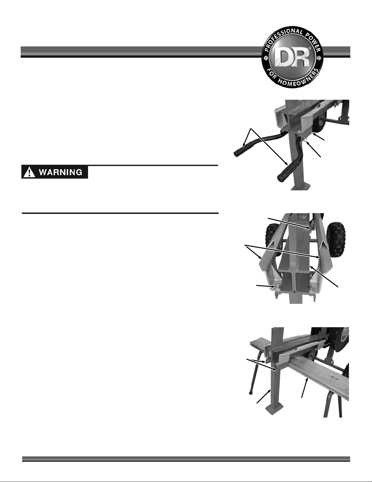
1. Remove the Handles by pulling the Handle Pins and removing the Bolts and
Locknuts us ing two 9\16 " Wrenches (Figure 1).
2. Loosen (do not remove yet) the eight Bolts, Flat Washers and Locknuts
securing the two Carriages with two 9\16" Wrenches (Figure 2)
3. Install Wheel Chocks and place a Sawhorse under the front part of the
Frame to lift the Supporting Leg off the ground (Figure 3).
4. Remove the eight Bolts, Flat Washers and Locknuts securing the two
Carriages with two 9\16 " Wrenc hes and store the Carriages.
Note: The Support Leg and Handle Brackets will come off when the forward
Carriage hardware in removed. S tore the Handle Brackets with the
Carriages. All Hardware will be reused.
Figure 1
Rear Hardware
Carriage
Front
Hardware
Figure 2
Brackets
Frame
Rapidfire™ Tray Kit# 27589
Sawhorse
Leg
Figure 3
Page 2
Support
Tray
Pins
Leg
Figure 4
Tray
Hardware
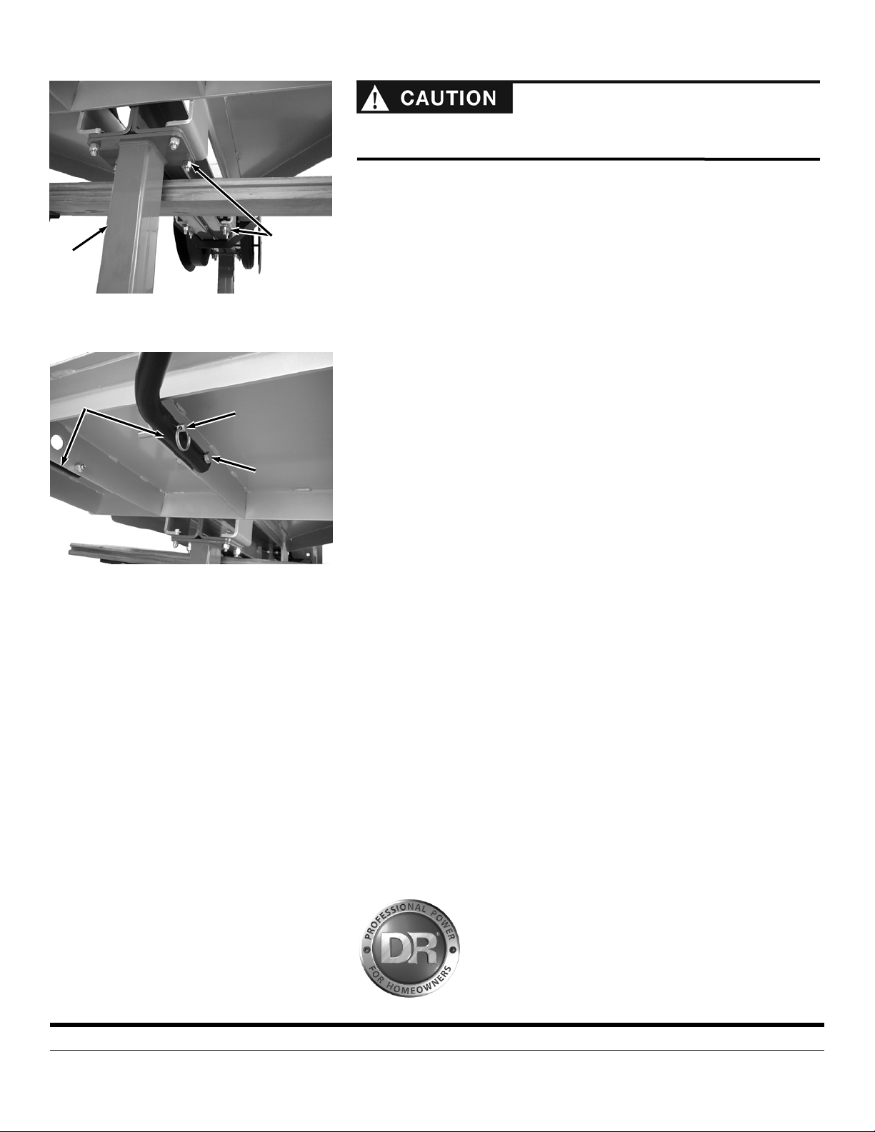
You will need another person to position the Tray. The Tray weighs over
60lbs. and lifting alone may cause injury.
5. Position the Tray onto the mounting holes of the Frame and loosely reinstall
the four rear Bolts and Locknuts into the Tray and Frame (Figure 4).
6. Position the Support Leg and install the four front Bolts and Lock Washers
through the Tray, Frame and Leg. Tighten all Tray hardware using two 9\16"
Wrenc hes
7. Install the Handles on the two center ribs of the front of the Tray with the
Bolts and Locknuts using two 9\16 " W re nch es (Figure 5). Rotate the
Handles up and secure with the Pins.
8. Remove the Sawhorse and Wheel Chocks from the machine.
Handles
Figure 5
If you have any questions please contact us at www.DRpower.com or call 1-800DR-OW N ER (3 76-9637) for assistance.
Hardware
75 MEIGS ROAD, P.O. BOX 25, VERGENNES, VERMONT 05491
©2011 Country Home Products, Inc. All rights reserved 275911
 Loading...