

DR 10.5HP PRO-26, 20.0HP PRO XL30, 14.5HP PRO-26, 16.5HP PRO XL 30, 20.0HP PRO MAX Safety & Operating Instructions Manual

DR
SAFETY & OPERATING INSTRUCTIONS
®
FIELD and BRUSH MOWER
Models:
10.5HP PRO-26
14.5HP PRO-26
16.5HP PRO XL 30
20.0HP PRO XL30
20.0HP PRO MAX
Serial No.
Order No.
Read and understand this manual and all instructions before operating the DR FIELD and BRUSH MOWER.
Original Language
DR Power Equipment
Toll-free phone: 1-800-DR-OWNER (376-9637)
Fax: 1-802-877-1213
Website: www.DRpower.com

2 DR
®
FIELD and BRUSH MOWER

Table of Contents
y
Chapter 1: General Safety Rules ............................................................................................................................................................ 4
Chapter 2: Setting Up the DR FIELD and BRUSH MOWER ................................................................................................................ 8
Chapter 3: Operating the DR FIELD and BRUSH MOWER ................................................................................................................. 13
Chapter 4: Maintaining the DR FIELD and BRUSH MOWER .............................................................................................................. 18
Chapter 5: Troubleshooting .................................................................................................................................................................. 24
Chapter 6: Parts Lists, Schematic Diagrams and Warranty ................................................................................................................. 26
Conventions used in this manual
This indicates a hazardous situation, which, if not avoided, could result in death or serious injury.
This indicates a hazardous situation, which, if not avoided, could result in minor or moderate injury.
This information is important in the proper use of your machine. Failure to follow this instruction could result in damage
to
our machine or property.
Serial Number and Order Number
A Serial Number is used to identify your machine and is located on the Serial
Number Label on your machine (Figure 1). An Order Number is used to check
and maintain your order history and is located on your packing slip. For your
convenience and ready reference, enter the Serial Number and Order Number in
the space provided on the front cover of this manual.
Additional Information and Potential Changes
DR Power Equipment reserves the right to discontinue, change, and improve its
products at any time without notice or obligation to the purchaser. The
descriptions and specifications contained in this manual were in effect at
printing. Equipment described within this manual may be optional. Some
illustrations may not be applicable to your machine.
Serial Number Label
Figure 1
CONTACT US AT www.DRpower.com 3

Chapter 1: General Safety Rules
#
#
#
Read this safety & operating instructions manual before you use the DR FIELD and BRUSH MOWER. Become familiar with the
operation and service recommendations to ensure the best performance from your machine. If you have any questions or need
assistance, please contact us at www.DRpower.com or call toll-free 1-800-DR-OWNER (376-9637) and one of our Technical
Support Representatives will be happy to help you.
Labels
The DR FIELD and BRUSH MOWER carries prominent labels as reminders for its proper and safe use. Shown below are copies of
all the Safety and Information labels that appear on the equipment. Take a moment to study them and make a note of their
location on your mower as you set up and before you operate the unit. Replace damaged or missing safety and information labels
immediately.
#35276
36373
#36372
#13649
13683
13758
#37045
Warnings, Cautions, and Notices
General Safety
Safe operation of the DR FIELD and BRUSH MOWER is necessary to prevent death or serious injury. Always take the following
precautions when operating this machine:
The DR FIELD and BRUSH MOWER is designed to mow grass and brush. Do not use it for any other purpose.
If the machine makes an unusual noise or vibration or if there are obstructions underneath the machine, shut off the DR
FIELD and BRUSH MOWER engine. Wait five minutes for the engine to cool. Disconnect the spark plug wire(s) and then
inspect the machine for clogs or loose parts. Clear any obstructions and repair and/or replace damaged parts.
The mower blades are sharp. Wrap the blades or wear gloves and use extra caution when servicing.
Always keep the machine in good, safe operating condition. Always make certain nuts and bolts are tight. Do not use
substitute hardware.
See manufacturer’s instructions for proper operation and installation of accessories. Only use accessories approved by DR
Power Equipment.
4 DR
®
FIELD and BRUSH MOWER

General Safety (Continued)
Use the DR FIELD and BRUSH MOWER only in daylight or very well lit work areas.
Be sure all blade and wheel controls are disengaged before attempting to start the engine. Engage and disengage the blade a
few times to get used to it before mowing.
Always give undivided attention to the machine and your surroundings. Watch for traffic when mowing near roadways.
Disengage the mower blades and exercise extreme caution when on or crossing drives, walks, or roads.
In an emergency, to quickly stop the cutting blade and shut off the engine, remove your hand from the operator presence
lever on the left handlebar.
Always shut off the engine whenever you leave the machine.
When operating over uneven and/or slippery terrain, use extreme caution to ensure solid and firm footing. Keep a firm hold
on the handlebars and walk, never run.
Do not operate the machine when under the influence of drugs, alcohol, or medication.
Protecting Yourself and Those around You
This is a high-powered machine with moving parts operating at high speeds. Always take the following precautions when
operating this machine:
Always wear protective goggles or safety glasses with side shields.
Wear sturdy shoes with non-slip treads.
Wear long pants while operating the mower.
Avoid wearing loose clothing or jewelry which can catch on moving parts
Use ear protectors or ear plugs.
We recommend wearing gloves while mowing. Be sure your gloves fit properly and do not have loose cuffs or drawstrings.
Allow only responsible adults who are familiar with these safety rules and operating instructions to use your DR FIELD and
BRUSH MOWER.
Keep your hands and feet away from the blades, belt, pulley, and concealed areas while the engine is running.
Keep people and pets away from your machine and out of the work area at all times. Disengage the blade and stop the engine
if a person or pet is within 100 feet of the machine.
Children are often attracted to the machine and the mowing activity. Never assume that children will remain where you last
saw them.
Never allow people to ride on the mower.
Before mowing, clear the area of objects such as rocks, toys, wire, bones, sticks, etc.
Never remove or alter standard parts or add anything to the DR FIELD and BRUSH MOWER especially all shields and guards.
Before and while moving backwards, look behind, and down, for small children.
Use extra care when approaching blind corners, shrubs, trees, or other objects that may obscure your vision.
Use caution when mowing close to fences, buildings, and trees so as not to hit the handle bar. You could injure your hand or
lose control of the machine.
Slope Operation
Slopes are a major factor related to slip and fall accidents. All slopes require caution. If you feel uneasy on a slope, do not mow it.
Always take the following precautions when using this machine on slopes:
Always mow across the face of slopes. Exercise extreme caution when changing direction on slopes.
Never operate near drop-offs, ditches, or embankments, or on slopes greater than 20 degrees
Never operate on wet or slippery slopes.
CONTACT US AT www.DRpower.com 5

Safety with Gasoline - Powered Machines
Gasoline is a highly flammable liquid that gives off flammable vapor that can be ignited and cause a fire or explosion. Always
follow these precautions:
Never run the engine in an enclosed area or without proper ventilation as the exhaust contains carbon monoxide, an odorless,
tasteless, and poisonous gas.
Store all fuel and oil in containers specifically designed and approved for this purpose. Keep away from heat and open flame
and out of the reach of children.
Replace rubber fuel lines and grommets when worn or damaged or after 5 years of use, whichever comes first.
Fill the gasoline tank outdoors with the engine off and after the engine has cooled completely. Do not handle gasoline if you
or anyone nearby is smoking.
If you spill gasoline do not start the engine. Move the machine away from the area until the gas vapors have dissipated.
Before performing engine maintenance or repairs; shut down the engine, disconnect the spark plug wire(s), and wait 5
minutes for the engine to cool.
Never change the engine governor settings or modify the engine speed.
Never check for an ignition spark with the spark plug or spark plug wire(s) removed. Always use an approved spark tester.
Never tamper with safety devices. Regularly check their proper operation.
Allow the engine to cool completely before storing in any enclosed area.
Keep combustible substances away from the engine when it is hot. Never cover the machine while the muffler is still hot.
To reduce fire hazard, keep the engine and muffler free of debris build-up.
Do not operate the engine with the air cleaner or the carburetor air intake cover removed.
Do not use flammable solutions to clean the air filter.
Never operate the engine without the muffler and deflector, if so equipped. Inspect the muffler and deflector periodically and
replace if necessary.
Themufflerandenginebecomeveryhotandcancauseasevereburn.Donottouch.
California Proposition 65
California Proposition 65:
Engine exhaust and some of its constituents are known to the state of California to cause cancer, birth defects, and other
reproductive harm.
This product contains or emits chemicals known to the state of California to cause cancer, birth defects, and other
reproductive harm.
A Note to All Users
Under California law, and the laws of some other states, you are not permitted to operate an internal combustion engine using
hydrocarbon fuels without an engine spark arrester. This also applies to operation on US Forest Lands. All DR
BRUSH MOWERS shipped to California, New Mexico and Washington State are provided with spark arresters. Failure of the
owner or operator to maintain this equipment in compliance with state regulations is a misdemeanor under California law and
may be in violation of other state and/or federal regulations. Contact your appropriate local or state organization for specific
information in your area.
No list of warnings and cautions can be all-inclusive. If situations occur that are not covered by this manual, the operator must
apply common sense and operate this DR FIELD and BRUSH MOWER in a safe manner. Contact us at www.DRpower.com or call
1-800-DR-OWNER (376-9637) for assistance.
®
FIELD and
6 DR
®
FIELD and BRUSH MOWER

CONTACT US AT www.DRpower.com 7

r
l
Chapter 2: Setting Up the DR FIELD and BRUSH MOWER
k
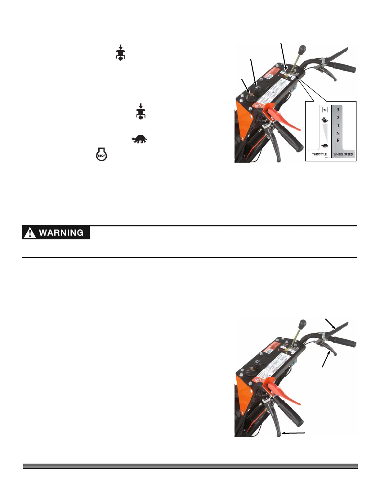
It may be helpful to familiarize yourself with the controls and features of your DR FIELD and BRUSH MOWER as shown in Figure
2 before beginning these procedures. If you have any questions at all, please feel free to contact us at www.DRpower.com.
DR FIELD and BRUSH MOWER Controls and Features
Wheel Speed
Leve
Right
Brake/Steering
Lever
Muffler
Oil Filter
Pull Start
Handle
Fuel Fill
Fuel Fill
20 hp Shown (14.5
hp and 16.5 hp
Engines Similar)
Belt Guard
PTO Knob
(Blade On/Off)
Key
Switch
Control Pane
Oil Fill/
Dipstick
Oil Drain
Traction
Drive
Lever
Throttle Lever
Operator Presence
Control Lever
Left
Brake/Steering
Lever
Fuel Tan
10.5 hp Engine
8 DR
Brush Bar
®
FIELD and BRUSH MOWER
Muffler
Brush Deck
Brush Blade
(Under Deck)
Fuel Filter
ON
Fuel Shut-Off Valve
Figure 2

Specifications
Engine See Engine Owner’s
Fuel Capacity 3 Quarts 2 Gal. (7.57 L) 2 Gal. (7.57 L) 2 Gal. (7.57 L) 2 Gal. (7.57 L)
Cutting Capacity
Cutting Width 26" 26" 30" 30" 34"
Cutting Height 4" 4" 4" 4" 4"
Speeds
Power Steering
Tires
Machine
Dimensions
Machine Weight
10.5 HP PRO-26 14.5 HP PRO-26 16.5 HP PRO XL 30 20.0 HP PRO XL30 20.0 HP PRO MAX 34
See Engine Owner’s
Manual
4' Tall Grass
8' Tall Brush
2" Thick Saplings
3 Forward
1 Reverse
No No Yes Yes Yes
18" x 6-1/2" x 8"
All Terrain
Sealant Filled
80.5” L
30.25” W
48.2” H
268 lbs. 290 lbs. 303 lbs. 325 lbs. 339 lbs.
Manual
4' Tall Grass
8' Tall Brush
2-1/2" Thick Saplings
3 Forward
1 Reverse
18" x 6-1/2" x 8"
All Terrain
Sealant Filled
80.5” L
30.25” W
48.2” H
See Engine Owner’s
Manual
6' Tall Grass
8' Tall Brush
2-1/2" Thick Saplings
3 Forward
1 Reverse
18" x 6-1/2" x 8"
All Terrain
Sealant Filled
83” L
33” W
48.2” H
See Engine Owner’s
Manual
6' Tall Grass
8' Tall Brush
3" Thick Saplings
3 Forward
1 Reverse
18" x 6-1/2" x 8"
All Terrain
Sealant Filled
83” L
33” W
48.2” H
See Engine Owner’s
Manual
6' Tall Grass
8' Tall Brush
3" Thick Saplings
3 Forward
1 Reverse
18" x 6-1/2" x 8"
All Terrain
Sealant Filled
84.5” L
38” W
48.2” H
SETUP for DR FIELD and BRUSH MOWER ATTACHMENTS:
The DR FIELD and BRUSH MOWER is shipped with a Brush Deck. It will also
accept other attachments including the DR SNOWTHROWER, DR CHIPPER
ATTACHMENT, DR LAWNDECK and DR SNOW/GRAVEL BLADE. Setup of
these attachments is quick and easy. Instructions to install and remove the
individual attachments can be found in their user manuals.
Installing the Brush Deck
Tools and Supplies Needed:
Gloves
Wire Cutters
1. Cut Cable Tie and remove Detent Pin and Collar from Power Unit (Figure 3).
2. Slide the Power Unit Pin into the Deck Bracket and install the Collar and
Detent Pin (Figure 4).
3. Remove the Belt from the Product Package.
Detent Pin
Figure 3
Detent Pin
Collar
Power
Unit Pin
Cable Tie
Power
Unit Pin
Collar
OFF
Deck
Bracket
Figure 4
CONTACT US AT www.DRpower.com 9

Belt
g
Figure 5
Deck Pivot
Bracket
Tensioner
Sprin
4. Insert the belt over the Tensioner Spring and through the inside of the Deck
Pivot Bracket (Figure 5).
5. Wrap the Belt around the Clutch Pulley under the Power Unit (Figure 6).
Your hands could get pinched when installing the Belt onto the Deck Pulley.
Wear Gloves to prevent injury.
6. Start the Belt into the groove of the Deck Pulley and turn the Pulley as you
guide the Belt around and into the Pulley groove (Figure 7).
7. Install the Belt Guard that was shipped with the machine and secure with the
Knob from the product package (Figure 8).
Figure 6
Figure 7
Belt
Clutch
Pulley
Idler
Pulley
Blade
Pulley
Removing the Brush Deck
It is recommended that the deck only be removed when installing other
attachments or performing maintenance.
The Power Unit should always have an Attachment installed for stability.
Tools and Supplies Needed:
Gloves
Flat Head Screwdriver
1. Unscrew the Knob that secures the Belt Guard to the Deck and remove the
Guard (Figure 8).
2. Place a screw driver between Blade Pulley and Belt.
3. While rotating the Blade Pulley, roll the belt off of the Blade pulley.
4. Push the belt in toward the Power Unit and the belt will fall off the Clutch
Pulley (Figure 6).
5. Pull the belt toward the deck to remove the Belt entirely.
6. Remove the Collar and Detent pin (Figure 4).
7. Shift the Wheel Speed Lever into Neutral.
8. Pull the Power unit back to release the Power Unit Pin out of the Deck Pivot
Bracket.
Knob
Belt Guard
Figure 8
10 DR
®
FIELD and BRUSH MOWER

Connecting the Battery Wire
We ship all Electric-Starting Mowers with the negative terminal Battery wire
disconnected. This prevents the Battery from discharging during shipment.
Before using your Mower, you must connect the Battery wire.
1. Connect the negative (black) wire to the negative terminal on the Battery by
sliding the Connector onto the Terminal (Figure 9).
Adding Oil and Gasoline
Negative
Battery Wire
Battery
Figure 9
Before filling the Fuel Tank; turn the Engine OFF, and let it cool at least five
minutes before removing the Gas Fill Cap
Note: Please refer to your Engine Owner’s Manual for detailed oil information
regarding Oil weight based on ambient temperature
You must add Oil before starting the engine. This machine is shipped
without oil. Traces of oil may be in the reservoir from factory testing, but
you must add oil before starting the engine
. Fill the reservoir slowly,
checking the level frequently to avoid overfilling.
To get an accurate reading when checking the oil level:
- The machine should be on a level surface.
- The dipstick SHOULD
Engines to ensure an accurate oil level reading.
1. Place the machine on a level surface and initially add 1/2 of oil
recommended by the Engine manufacturer into the Oil Fill (Figure 10,
Electric Start Machines) or (Figure 11, Manual Start Machines).
2. Wait one minute for the oil to settle and check the Dipstick. Continue
adding a few ounces of oil at a time, rechecking the Dipstick until the oil
reaches the full mark. Be careful not to overfill.
3. Fill the Fuel Tank to not more than 1/4" from the bottom of the Fill Neck
with fresh, unleaded gas. See your Engine Owner’s Manual for more
information.
be screwed down on Briggs & Stratton
Gas Fill Cap
Oil
Fill/Dipstick
Figure 10: Electric Start Machines
Oil
Fill/Dipstick
Figure 11: Manual Start Machines
(except Premier)
Gas Fill Cap (Premier Only)
Check the Tire Pressure
Do not over inflate the tires. Inflate to the manufacturers recommended
pressure found on the tires.
Tools Needed:
Tire Pressure Gauge
Air Compressor
1. Remove the Valve Stem Protective Cap (Figure 12) and check the tire pressure with a Tire Pressure Gauge.
2. Compare the tire pressure reading from step 1 with the manufacturer's recommended tire pressure stamped on the side of the
tire.
3. If the pressure is too low, add air through the Valve Stem with an air hose.
4. Replace the Valve Stem Protective Cap when finished.
Valve Stem
Protective Cap
Figure 12
CONTACT US AT www.DRpower.com 11

Handlebar Height Adjustment
We ship all DR Field and Brush Mowers with the handlebars in the highest
position setting. If you would like to lower the handlebars to the Low position
Handlebar High
Position hole
please follow these steps:
Tools Needed:
9/16” Wrench
1. Remove Rear Handlebar Bolt with a 9/16” Wrench from both handlebars
(Figure 13).
Handlebar Low
Position hole
Rear Handlebar
Bolt Removed
Figure 13
2. Loosen Front Handlebar Bolt on both handlebars but do not remove.
3. Align Handlebar Rear hole to Handlebar Low Position hole in the Frame.
4. Reinstall Rear Bolts on both handlebars.
5. Tighten Front and Rear Bolts on both handlebars.
Steering Brake Break-in
The Steering Brakes are standard equipment for the 16.5 HP and 20 HP Models. If your DR Field and Brush Mower is equipped
with Steering Brakes, the Brake Pads and Rotors need to be broken in (burnished) during the first use to ensure the best
performance. Please complete the following steps before using your machine and after you have read through Chapter 3:
Avoid contact with the Brake Calipers and Rotors during and after this procedure because the Brake rotors will become very hot
and may burn you.
1. Refer to Chapter 3 to start the machine and shift into second gear.
2. Engage the Traction Drive Lever to drive the machine forward.
3. Apply both brakes equally with moderate force and hold the brakes on for 100 feet.
4. Release the brakes for 25 feet.
5. Re-Apply both brakes equally with moderate force and hold the brakes on for another 100 feet.
12 DR
®
FIELD and BRUSH MOWER

Chapter 3: Operating the DR FIELD and BRUSH MOWER
r
You may find it helpful to review the DR FIELD and BRUSH MOWER Controls and Features in Figure 2 on page 8 before reading
this chapter.
Before Starting the Engine
1. Check the Engine Oil level every time before you use the machine (Figure
10/11 on page 11).
2. Check the gas level (Figure 10/11 on page 11).
3. Ensure that the Fuel Shut-Off Valve located under the Fuel Tank is open
(Figure 14).
Gas
Tank
CLOSED
Starting
ELECTRIC STARTING
1. Move the Wheel Speed Lever to Neutral
N (Figure 15).
Note: The Wheel Speed Lever must be in Neutral and the Blade Control Knob
pushed down (OFF), or the Engine will not start.
2. Check that the Neutral Safety Switch at the rear of the Transaxle is connected
in case it has loosened during shipping (Figure 16).
3. Move the Throttle Lever to Choke
(to Fast if the Engine is already
warm) (Figure 15).
4. Rotate Key to the Start position
The Key will return to the Run
until the Engine starts, then release.
position and the Engine will continue to
run.
5. Move the Throttle Lever to the Fast
MANUAL STARTING (10.5HP MODEL)
1. Move the Shift Lever to Neutral
N (Figure 15).
position.
Note: The Wheel Speed Lever must be in Neutral and the Blade Control Switch
pushed down (OFF), or the Engine will not start.
2. Move the Throttle to Choke
(to Fast if the Engine is already warm).
Fuel
Shutoff
Valve
Figure 14
Throttle Lever
Blade Control
Knob
Key
Switch
Figure 15
OPEN
Wheel Speed
Leve
3. Rotate Key to the Run
position.
Neutral
Safety
Switch
Figure 16
CONTACT US AT www.DRpower.com 13

Pull Start
Handle
4. Grasp the Recoil Starter Handle and slowly pull until you feel resistance
(Figure 17). Let the Cord retract a little bit, and then pull the Cord rapidly to
start the Engine.
Figure 17
Wheel Speed
Lever
Traction Drive
Lever
5. When the Engine starts, move the Throttle to the Fast
position (Figure
15).
Engaging the Wheel Drive
The DR FIELD and BRUSH MOWER has a three-speed Forward, single-speed
Reverse Transmission. Speeds are generally used as follows:
st
1
Gear: Thick, woody vegetation.
nd
2
Gear: Stalky material or Field Mowing.
rd
3
Gear: Lighter Mowing or Transport mode.
Reverse Gear is ideal for maneuvering in tight spots.
While transporting the machine in 3rd Gear the Throttle can be used to
adjust speed.
When mowing the throttle should always be in the Fast Position.
Mowing Speed may impact cutting performance. Mowing in a slower gear
will improve cut quality.
For best operator control of the DR Field and Brush Mower, always select a
drive speed that matches the conditions. For example, use a slower speed
when operating in wet, heavy growth, slippery, and/or steeply sloped areas.
Always release the Traction Drive Lever before shifting gears to prevent
damage to the Transmission.
1. Move the Wheel Speed Lever to the desired gear (Figure 18).
2. Gently push down the Traction Drive Lever to engage the Wheels.
Figure 18
Blade Control
Knob
Figure 19
14 DR
Operator Presence
Control Lever
®
FIELD and BRUSH MOWER
3. Release the Traction Drive Lever if you need to slow down or stop.
The steering brakes WILL NOT STOP the machine if the machine is in gear
and Traction Drive Lever is engaged.
Note: If you have trouble shifting while on a hill or against an obstacle; lifting one
tire off the ground will release the stress in the drivetrain and ease shifting.
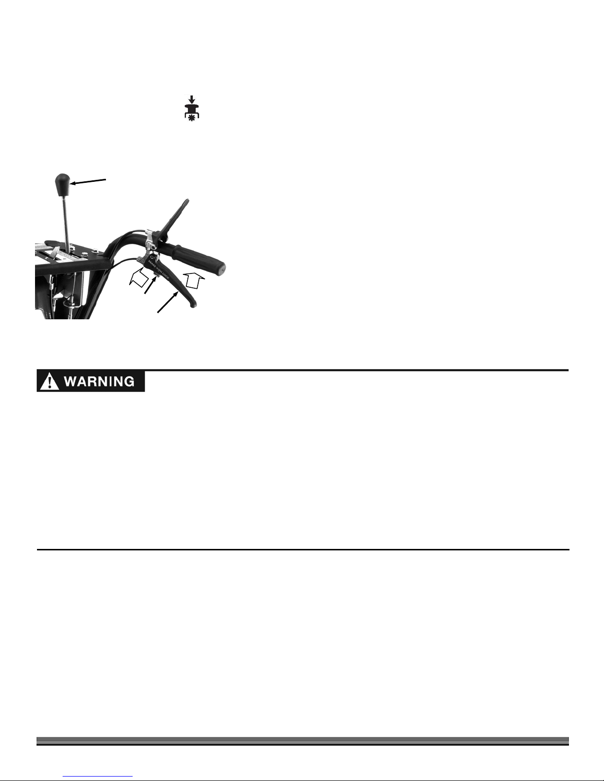
Engaging the Blade
1. Push down the Operator Presence Lever against the Handlebar Grip (Figure
19).
2. Engage the Blade by pulling up
Note: If you pull up on the Blade Control Knob before holding down the Operator
Presence Lever, the Engine will shut off.
Always disengage the blade of the DR FIELD and BRUSH MOWER before
shifting into reverse.
on the Blade Control Knob.
Stopping the Blade
1. Stop the Blade by pushing down on the Blade Control Knob (Figure 20).
Note: Releasing the Operator Presence Lever to disengage the Blade will cause the
Engine to shut off.
Stopping the Engine
1. Disengage the Blade by pushing DOWN on the Blade Control Knob
Knob (Figure 20).
Throttle Lever
Blade Control
Knob
Key
Switch
2. Move the Throttle Control to the IDLE
3. Turn the Key to the Stop
position and remove it for safety.
Note: If your machine is equipped with a Fuel Shut-Off Valve, close it when
position.
Figure 20
transporting or storing the Mower.
Obstacle Tips
Dealing with obstacles in the terrain is easy with your new DR FIELD and BRUSH MOWER. The following section explains how to
approach most common obstacles.
The mower’s blade can easily throw stones, sticks, and other debris at great velocity, which could cause personal injury or property
damage. Do not run the machine over gravel driveways or over loose stones or mulch with the mower blade spinning.
Always check your work area before mowing and remove any debris that might tangle or damage the machine.
If you do run into debris and the mower becomes tangled, turn off the Engine, allow the engine to cool for 5 minutes and
disconnect the Spark Plug wire(s) before attempting to untangle the machine.
Operating the Steering Brakes:
Steering brakes can assist the operator in:
Shifting the drive power from one wheel to the other to improve traction.
Keeping the mower driving straight on side slopes.
Turning the machine left or right.
The brakes apply a stopping force to the wheel on the same side as the brake
lever. For example, when the left lever is squeezed the brake slows or stops the
left wheel and transfers transaxle power over to the right wheel.
Traction Drive
Lever
Steering with Brake Assist:
1. Select a Gear most applicable to the situation (see “Engaging Wheel Drive”
on previous page).
2. Press down on the Traction Drive Lever to drive the machine (Figure 21).
3. Turn the machine to the left by squeezing the Left Brake Lever.
4. Turn the machine to the right by squeezing the Right Brake Lever.
Note: the machine must be driving for the brakes to assist with steering.
Right Brake
Lever
Left Brake
Lever
Figure 21
CONTACT US AT www.DRpower.com 15
1 2
Traction Control with Brakes:
Occasionally, the machine may lose traction on one or both wheels. To gain traction, perform the following steps:
1. Stop the Blade by pushing down
2. Apply the brake to the spinning wheel and the power will be directed to the wheel that has more traction.
3. If both wheels are spinning try alternating the brakes left and right to maneuver the machine through the obstacle.
Wheel Speed
Lever
Brake Lock
Pin
Brake Lever
Figure 22
on the PTO Knob (Figure 20)
Setting the Parking Brakes:
For machines equipped with Steering Brakes. Machines without Brakes should
be put in 1st gear and parked on a level surface.
1. Shift the Wheel Speed Lever to Neutral
2. Squeeze one of the Brake levers and push the Brake Lock Pin forward to set
the brake. The Brake Lever will stay up when locked properly.
3. Repeat step 2 for the other Brake.
N (Figure 22)
Mowing on Slopes
Slopes are a major factor related to slip and fall accidents. All slopes require caution. If you feel uneasy on a slope, do not mow it.
Always take the following precautions when using this machine on slopes:
Always mow across the face of slopes. Exercise extreme caution when changing direction on slopes.
Never operate near drop-offs, ditches, or embankments, or on slopes greater than 20 degrees
Never operate on wet or slippery slopes.
When operating the DR FIELD and BRUSH MOWER over uneven terrain or slopes, use extreme caution not to tip the machine
over.
Do not use the DR FIELD and BRUSH MOWER on slopes greater than 20 degrees. Doing so could result in serious injury or
damage to your machine.
Do not shift while on a slope, doing so could result in a “free-wheel” condition.
Be very careful of your footing when operating the machine in reverse. Know what's behind you and take your time.
Disengage the Blade before shifting into reverse. Mow in the Forward gears only, using Reverse for maneuvering.
1. While mowing on sloped terrain, mow across the face of the slope. Do not mow up and down.
2. To avoid excessive speed, shift into a lower gear before going down a slope.
Tip: For machines equipped with steering brakes: When mowing on sidehills, feather the uphill brake to get the machine to steer
up the hill slightly. This should keep the machine moving in a straighter line without additional operator effort.
16 DR
®
FIELD and BRUSH MOWER

If the machine gets hung up
1. Disengage the Blade. Do not try to free the machine from stumps or debris with the Blade engaged.
2. Push down on the Handlebars to lift the Mowing Deck over the obstacle.
3. Shift the machine in reverse and try backing away from the obstacle.
Cutting Brush and Saplings
If you need to leave the operating position to clear debris from the deck, stop the engine, wait five minutes to allow all parts to
cool. Disconnect the spark plug wire(s), keeping it away from the spark plug(s).
1. When cutting woody material, small saplings, etc., allow the machine to ride up and over material slowly. Adjust your forward
speed to varying conditions.
2. After cutting brush, etc., you may want to mow over it again to remove any remaining branches. It works best to mow from
the trunk end toward the top as brush lies on the ground.
Cold Weather Operation
At temperatures below 30°F and a high dew point, the DR FIELD and BRUSH MOWER Engine may experience icing of the
carburetor and/or the crankcase breather system. DR Power Equipment offers an optional Engine cover to prevent icing in these
weather conditions. You can purchase the cover through DR Power Equipment by visiting our website at www.DRpower.com.
Please have your DR FIELD and BRUSH MOWER Model# and Serial# at hand when the call is placed.
CONTACT US AT www.DRpower.com 17

Chapter 4: Maintaining the DR FIELD and BRUSH MOWER
P
Regular maintenance will ensure the best performance and long life of your machine. Please refer to this manual and the engine
manufacturer's owner's manual for maintenance procedures. Service intervals listed in the checklist below supersede those listed
in the engine manufacturer's owner's manual.
Before performing any maintenance procedure or inspection, stop the engine, wait five minutes to allow all parts to cool.
Remove the Key and disconnect the spark plug wire(s), keeping it away from the spark plug(s)
Always wear gloves when performing maintenance on the machine.
Regular Maintenance Checklist
ROCEDURE BEFORE EACH USE
Check Operator Presence Switch
Check Engine Oil Level
Check General Equipment Condition
Check Blade for Sharpness
Clean Engine Exterior and Cooling Fins
Check All Belt Tensions and Condition
Brake Maintenance
Lubricate Grease Fittings
Lubricate Cables
Check Tire Pressures
Change Engine Oil and Filter** 1
Check the Battery charge
Check cable connections
Replace Air Filter and Precleaner**
Replace belts
Replace Spark Plug(s)
Replace Fuel Filter
** The Engine on your machine may not have a Precleaner or Oil Filter.
st
time 5 hours
EVERY 25 HOURS EVERY 100 HOURS
LUBRICATION
Oil Container
Figure 23
18 DR
®
FIELD and BRUSH MOWER
Oil Drain Hose
Replacing Engine Oil and Filter
Note: Drain the oil when the Engine is warm. Warm oil drains quickly and
completely.
Tools & Supplies Needed:
Oil Filter Wrench (obtainable from a local auto parts or hardware store)
Oil (Refer To Engine Operator Manual for Oil info and Capacity)
Rags and an approved oil container
1. Position an approved oil container near the Oil Drain Hose.
2. Turn the Oil Drain Cap a quarter turn counterclockwise and open the end of
the Drain Hose Assembly (Figure 23).
3. Remove the Oil Drain Hose Assembly from its stowed position and lower
the drain end over the Oil Container to drain.
4. If the engine has an oil filter, remove the old Oil Filter with an Oil Filter Wrench and replace with a new Oil Filter as described
s
A
s
g
in the Engine Operator Manual.
5. Replace the Oil Drain Hose Assembly onto the Storage Hook and close the Oil Drain Cap. Replace the Oil as described in the
Engine Operator Manual.
Cable lubrication
Supplies Needed:
Multi-purpose Teflon Aerosol Lubricant
Lubricate the Traction Drive Cable, Shift Cables, Throttle Cable and Brake Cables where the Cable goes into the Sheathing with a
Multi-purpose Teflon Aerosol Lubricant
1. Spray the lubricant into the Cable Housing while working the Cable back and forth a few times. Perform this lubrication more
often in dry and dusty environments.
Idler Arm Lubrication
Tools & Supplies Needed:
Grease Gun w/General Purpose Grease
There is one Grease Fitting below the black Belt Guard to lubricate (Figure 24)
With the Blade Belt removed (Refer to “Removing the Brush Deck” on page 10),
move the idler arm to make sure it rotates freely. If resistance is felt when
pivoting the arm please lubricate as follows:
1. Remove the knob and belt guard from the deck.
2. Locate the Grease Fitting on the idler arm.
3. Using the grease gun add a small amount of grease (1-2 pumps or until
slight resistance).
Note: Over greasing may cause grease to leak onto the Mower Drive Belt.
4. Reinstall the Belt (if removed) and Belt Guard.
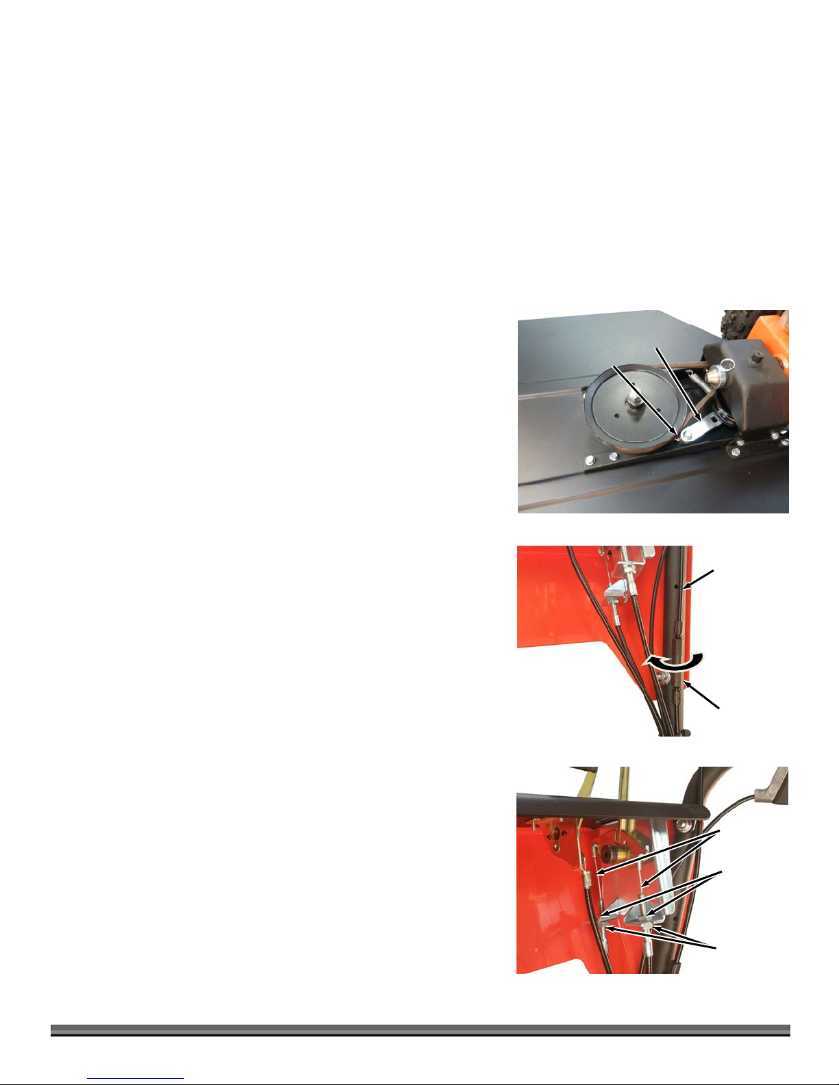
Adjusting the Traction Drive Cable
Note: When properly adjusted, tension on the Traction Drive Lever should increase
when the Lever is about parallel to (almost touching) the Handlebar Grip.
1. Locate the Traction Drive Cable along the right Handlebar (Figure 25). There
is an In-Line Adjuster to change the length of the Cable.
2. Rotate the center portion clockwise while holding the ends stationary to
expand the In-Line Adjuster and remove slack from the cable.
Grease Fitting
Figure 24
Idler Arm
Traction
Drive Cable
Rotate Center
Section
Clockwise to
Ti
hten
In-Line Adjuster
Adjusting the Shift Cables
If there is a lot of “play” in the Wheel Speed Lever or if the lever is no longer aligned
with the Wheel Speed Label, you may need to adjust the Shift Cables.
Tools needed:
Two 13mm Wrenches
1. Locate the Shift Cable Adjustment Nuts on the Shift Lever end of the cable
(Figure 26).
2. Loosen one of the Cable Jam Nuts on the cable using two 13mm Wrenches.
3. Pull down slightly on the cable just enough to pull out the slack and then
tighten the Cable Adjustment Nut to hold the cable housing in tension. You
may need to tension one cable while loosening the other to realign the
Lever.
Note: Do not over tighten the cable. It will create a spongy feel in the shift lever.
Figure 25
Shift Cables
Cable Jam
Nut
Cable
djustment
Nut
Figure 26
CONTACT US AT www.DRpower.com 19
A
s
Clutch
A
To Replace the Drive Belt
Tools and Supplies Needed:
Ratchet
1/2" Socket
5/8" Socket
#2 Phillips Screwdriver
Gloves
Figure 27
Figure 28
Clutch Connector
Clutch Connector
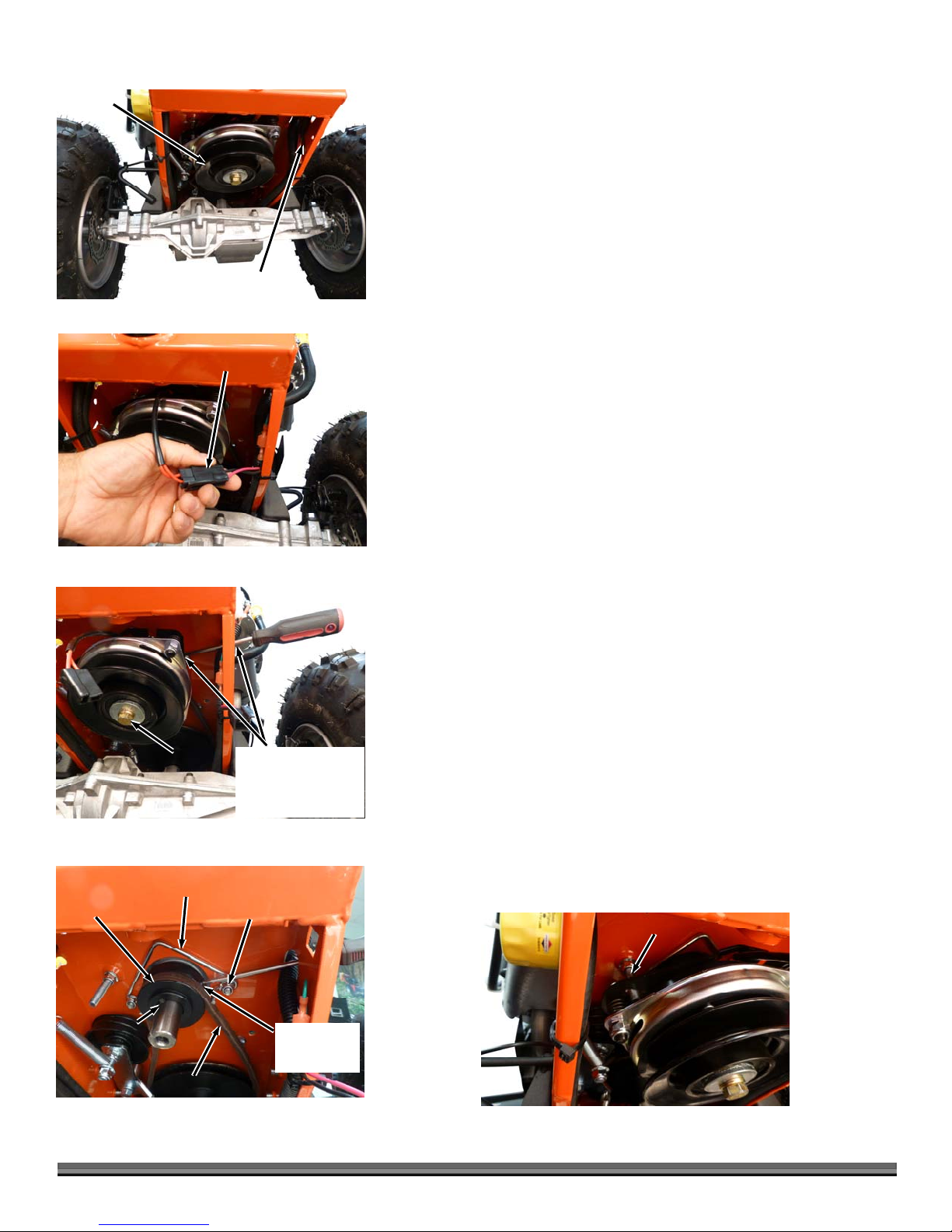
1. Remove the Brush Deck (See section “Removing the Brush Deck” on page
10) and tip the machine back on its handlebars to access the Clutch
Connector under the machine (Figure 27).
2. Disconnect the Clutch Connector by lifting the locking tab and separating
the two halves (Figure 28).
3. Locate the hole in Traction Drive Pulley (Figure 29 and 30) on the engine
and insert the Phillips head screwdriver through the opening in the Frame
and into the hole in the Pulley (Figure 29).
4. If the hole is not aligned with the Screwdriver, turn the Clutch Bolt with the
5/8" Socket until the screwdriver goes into the hole.
5. Rotate the Clutch Bolt (direction to loosen) until the screwdriver rests
against the frame (this is to keep the engine shaft from rotating in the next
step).
6. Remove the Clutch Bolt using a 5/8" Socket. The Clutch Bolt has standard,
right hand threads (Use impact wrench if possible).
7. Remove Clutch from engine shaft.
8. Remove the nuts retaining the belt guide with a 1/2" socket (Figure 30).
9. Remove the Key from the Traction Drive Pulley and shift the transmission to
Neutral
N.
10. Rotate the Pulley as you pull the belt out of the pulley groove.
Figure 29
Traction Drive
Pulley
Shaft Key
Figure 30
20 DR
Clutch Bolt
Belt Guide
Belt
®
FIELD and BRUSH MOWER
Screwdriver through
frame opening and
into Hole in Traction
Drive Pulley
Retaining
Nut
11. Remove the belt from the Transmission by rotating it 90° and sliding it
between the Transmission Pulley and the Frame.
12. Reinstall the new belt by reversing the above procedures.
During reassembly make sure that:
The Shaft key is installed in the engine shaft.
The belt is on the inside of the belt guides (Figure 30).
The clutch is located properly on the Anti-Rotation Bolt (Figure 31).
You torque The Clutch Bolt to 50lb-fts (68N-m).
nti-Rotation Bolt
Screwdriver
nti-Rotation
Hole
Figure 31
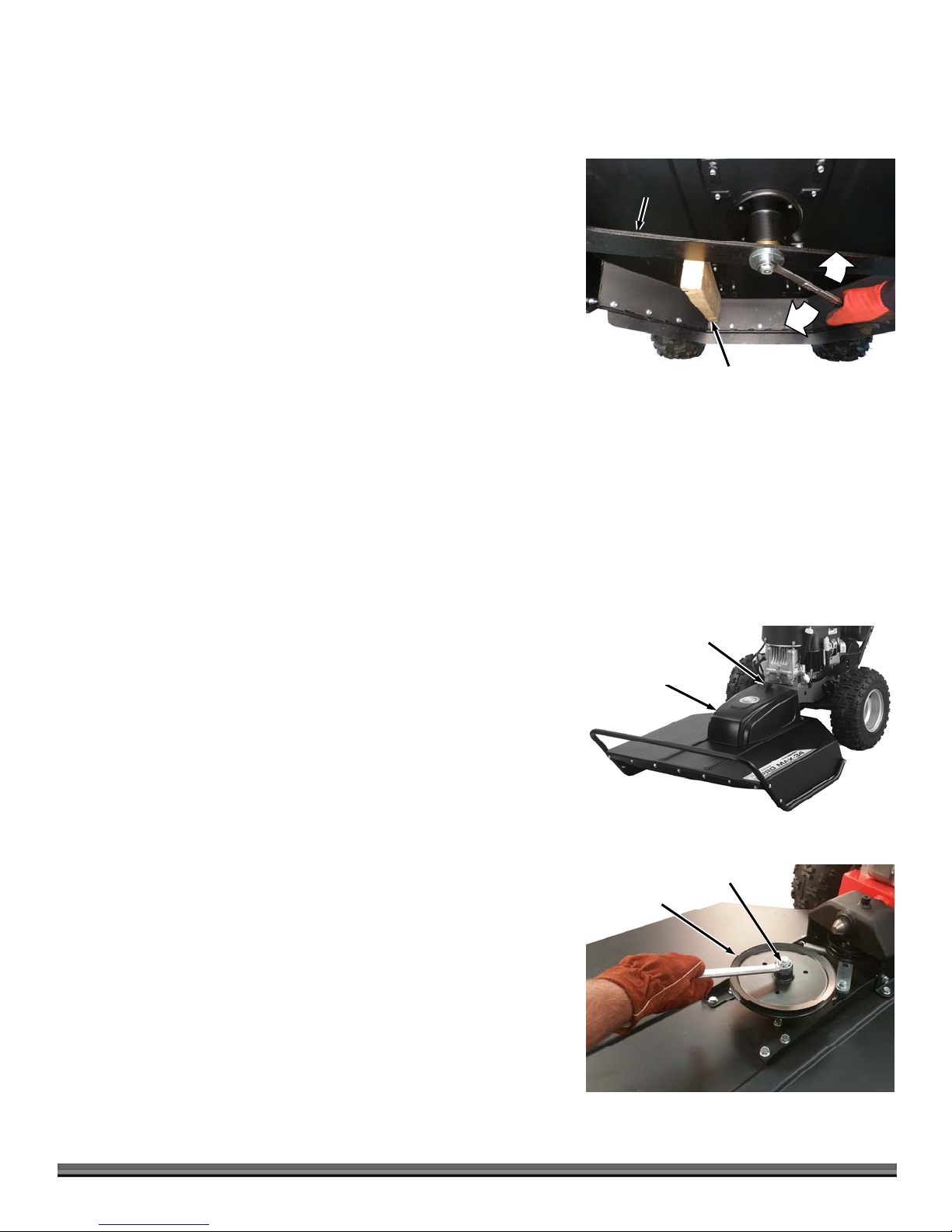
Removing and Replacing the Blade
Replace the Blade when worn or damaged, but do not use it for over five years.
Tools and Supplies needed:
15/16" Wrench or Socket
Torque Wrench (optional)
Gloves
2" x 4" to brace the Blade
1. Block the Blade with a piece of wood between the Blade and the Skid on the
side of the Deck
(Figure 32).
Blade
Loosen
2. Remove the Blade Lock Nut (standard, right-hand thread) and Washer.
3. Remove the Blade.
4. Mount the new Blade, Washer, and Lock Nut and tighten securely (Torque
to 100 ft-lbs.). If the Locknut is removed and installed more than once, it
should be replaced with a new one.
NOTE: Be sure to seat the Blade completely over the small ridge in the Spindle Hub
before tightening the Lock Nut.
Removing the Wheels
Tools and Supplies needed:
3/4" Socket with extension
1. Loosen the Wheel Nuts a couple of turns with the Wheel on the ground.
2. Block the machine so the Wheel you are removing is off the ground.
3. Remove the Five Nuts and slide the Wheel off.
4. Replace the Wheel and finger-tighten the Wheel Nuts before unblocking the
machine.
5. Tighten the Wheel Nuts with the Wheel resting on the ground.
Replacing the Blade Pulley
The Bladed Pulley is designed to protect the drive system of the machine. If the
machine is overloaded the hub and pulley may fail. Please follow these
instructions to replace
Tools and Supplies Needed:
15/16" Wrench
1. Unscrew the Hand Knob and remove the Belt Guard (Figure 33).
Tighten
Wood Block
Figure 32
Knob
Belt Guard
Figure 33
2. Remove the Belt from the Pulley (Refer to “Removing the Brush Deck” on
page 10).
3. Block the blade with a piece of wood (Figure 32) as you remove the Locknut
using a 15/16" Wrench (Figure 34).
4. Remove the damaged Pulley and replace with a new Pulley.
5. Secure the Pulley with the Locknut and torque to 50lb-fts (68N-m).
6. Install the Belt (Refer to “Installing the Brush Deck” on page 9).
7. Replace the Belt Guard and Hand Knob.
Lock Nut
Blade Pulley
Figure 34
CONTACT US AT www.DRpower.com 21

per
Cable
Micro Adjust
Knob
Brake
Cali
Adjusting the Brake Cables
Tools needed:
5.5mm Allen Wrench
On each brake caliper there is a tool free Micro Adjust Knob (Figure 35). For
most maintenance this knob can be unscrewed and will tension the cable.
Once the Micro Adjust Knob is close to the end of its thread travel, it is
recommended to do a full adjustment.
Cable
Clamp
Figure 35
Figure 36
Brake
Pad
Brake
Rotor
Pad Adjustment
Screw
Note: Although not mandatory, it is recommended that the wheel be removed
before completing a full adjustment.
1. Screw the Micro Adjust Knob all the way back into the caliper.
2. Using the 5.5mm Allen Wrench, loosen the Cable Clamp.
3. Pull the cable through the clamp removing and slack in the cable.
4. While holding tension on the cable, retighten the Cable Clamp with the
5.5mm Allen wrench.
Adjusting the Brake Pads
Tools needed:
5.5mm Allen Wrench
Note: Brake Pads may need adjustment after the pads wear significantly
1. Remove the wheel from the side that needs adjusting.
2. Locate the Pad Adjustment Screw on the outboard side of the caliper (Figure
36).
3. Tighten the adjustment screw using the 5.5mm Allen wrench until just
before the Brake Pad just touches the Brake Rotor.
Adjusting the Caliper Alignment
Tools needed:
5.5mm Allen Wrench
Caliper
Mounting
Bolt
Figure 37
22 DR
®
FIELD and BRUSH MOWER
Caliper
Mounting
Bolt
Brake
Caliper
Note: Caliper Alignment should only be done after the Brake Pads have been
adjusted
1. Remove the wheel from the side that needs adjusting.
2. Using the 5.5mm Allen Wrench, loosen the Caliper Mounting Bolts 1 turn
(Figure 37).
3. While manually Squeezing the caliper closed on the Brake Rotor, Retighten
the Caliper mounting Bolts.

Battery Care (electric start machines only)
Proper care can extend the life of a Battery. Follow these recommendations to ensure your Battery’s best performance and long
life:
Do not allow the Battery charge to get too low. If the machine is not used, charge the Battery every 4 – 6 weeks. Operate the
Engine for at least 45 minutes to maintain proper Battery charge.
Store an unused Battery in a dry area that does not freeze.
Do not charge an already charged Battery. In theory, you cannot overcharge our Battery with a trickle Charger; however, when
a Battery is fully charged and the Charger is still on, it generates heat that could be harmful to the Battery. A fully charged
Battery will read 12V-13.2V with a Voltmeter.
Do not continue to crank the Engine when the Battery charge is low.
Charging the Battery
Operate the Mower Engine for at least 45 minutes to maintain proper Battery charge. If the Battery loses its charge, you'll need to
use a trickle Charger (like the DR Battery Charger) to recharge it. The Charger should have an output of 12 volts at no more than 2
amps.
Note: The charging system of a running engine is designed to maintain a battery’s present charge. Starting a machine that has a
significantly discharged or dead Battery using the Recoil Starter or Jumper Cables will not recharge the Battery.
To connect a Battery Charger to your DR FIELD and BRUSH MOWER, follow the steps listed below.
1. Detach the two Battery wires going to the Battery on your DR FIELD and BRUSH MOWER.
2. Attach the black (-) Battery Charger wire to the Battery negative (-) terminal, and attach the red (+) Battery Charger wire to the
Battery positive (+) terminal.
3. Plug the Battery Charger into an outlet.
4. Charge until Battery Charger indicates that it is charged or Battery measures to 12-14V.
At 1 amp, you may have to charge the Battery for as long as 24 hours.
At 2 amps, you may have to charge the Battery for as long as 12 hours.
5. Once Charged, disconnect Charger from outlet.
6. Disconnect Battery from the Charger.
Disposing of the Battery Responsibly
The Battery is a sealed lead-acid Battery. Recycle or dispose of it in an environmentally sound way.
Do not dispose of a lead-acid Battery in a fire; the Battery may explode or leak.
Do not dispose of a lead-acid Battery in your regular, household trash. Laws in most areas prohibit incinerating, disposing in a
landfill, or mixing a sealed lead-acid Battery with household trash.
Please dispose of used batteries responsibly, according to your local hazardous materials regulations. Never throw away used
batteries in your household trash.
Recycling a Used Battery
Please dispose of your used Batteries responsibly by recycling them. Call your local Solid Waste Management District or your local waste
handler to locate the collection site nearest you. Some collection sites recycle Batteries year-round; others collect them periodically.
You can also visit the Web site of Earth 911 for more information [www.earth911.org]. Once there, click the Municipal HHW link under
Hazardous Household Waste, and enter your zip code. The site lists recycling centers located near you.
For a fee, you can recycle your Batteries with the International Metals Reclamation Company. Visit them at www.inmetco.com and click
Services; or contact them at: INMETCO, PO Box 720, 245 Portersville Road, Ellwood City, PA 16117, (724) 758-2825; fax (724) 758-2845.
To learn more about hazardous waste recycling, visit the Web site for Battery Council International [www.batterycouncil.org] or for the
Environmental Protection Agency [www.epa.gov].
CONTACT US AT www.DRpower.com 23

Chapter 5: Troubleshooting
Most problems are easy to fix. Consult the Troubleshooting Table below for common problems and their solutions. If you
continue to experience problems, contact us at www.DRpower.com or call toll-free 1-800-DR-OWNER (376-9637) for support.
Before performing any maintenance procedure or inspection, stop the engine, wait five minutes to allow all parts to cool.
Disconnect the spark plug wire(s), keeping it away from the spark plug(s).
Troubleshooting Table
SYMPTOM POSSIBLE CAUSE
Engine Starter Won’t
Crank
Engine Starter Cranks
but Engine wont start
The Engine lacks power
or is not running
smoothly.
(Please refer to the
Engine Owner’s Manual
for engine-specific
procedures.)
Engine smokes.
Traction Drive does not
Engage
Check all of the items under the section called “Starting” on page 13. Especially,
Transmission is in (N) and the PTO switch is in the depressed position
Check that the Plug for the Neutral Safety Switch is connected
Check the fuse located under the battery
Check the battery is more than 12V- Refer to Battery Care Section
Check all wire connections—especially the ground connections located on the handlebar and
all of the connections on the solenoid. Disconnect the green Battery ground wire first to avoid
sparks. Check to be sure that all of the connections are clean and tight. Reconnect the
Battery ground wire.
Check that the gas tank is atleast half full and that the fuel shut off is in the ON position
Check that the fuel solenoid switch on the carburetor bowl is connected
Try starting with the throttle in the CHOKE position; if this doesn’t work try the RUN position.
Check the Throttle Lever travel and adjustment. Make sure the Throttle Lever is in the Run
position.
Check that the Air Filter is clean. If it is dirty, change it following the procedure in the Engine
Owner’s Manual.
The Spark Plug(s) may be dirty or cracked, change it. If it’s oily, leave it out, hold a rag over
the Plug Hole(s) and crank the Engine several times to blow out any oil in the Cylinder(s),
then wipe off the Plug(s) and reinsert it.
The gas may be old, change it. Use a fuel stabilizer if you keep gas longer than one month.
Check the Fuel Filter, it may be clogged. Replace if necessary.
Check to make sure that your Engine has the right amount of clean oil. If it is dirty, change it
following the procedure in the Engine Owner’s Manual.
Check the oil level and adjust as needed.
You may be operating the machine on too great an incline. See “Mowing on Slopes” on page
16.
Check the Air Filter and clean or replace if needed.
You may be using the wrong oil—too light for the temperature. Refer to your Engine Owner’s
Manual for detailed information.
Clean the Cooling Fins if they are dirty.
If the Engine still smokes, visit our web site at www.DRpower.com for assistance.
The Drive Belt is broken or out of adjustment. See page 20.
Traction Drive Cable may need adjusting
that the
24 DR
®
FIELD and BRUSH MOWER

Troubleshooting Table (Cont.)
SYMPTOM POSSIBLE CAUSE
Machine is difficult to
shift
A Belt frays or rolls over
the Pulley.
Excessive vibration when
engaging the Blade.
The Blade is not cutting
or is loose.
The Blade will not
Engage and/or
Disengage.
Wheels pulling left or
right.
There may be added resistance from the driveline when trying to shift on a slope or while
pressing against an obstacle. Lifting one tire will relieve any residual load in the driveline and
shifting should become much easier.
If there is resistance between all gears, the shift cables may be overly tight. Loosen 1 cable
slightly and shifting feel should improve.
A Pulley groove may be rusty or have a nick in it. Clean the pulley with steel wool or file off any
nicks.
Check the Belt for wear and hard spots.
The Belt may be stretched, replace it.
Check the Blade for nicks and wear. Replace or sharpen and balance the Blade if they become
dull, or have them professionally sharpened if needed. Never try to straighten a bent Blade.
Be sure to replace the Blade in the proper orientation. See page 21.
May have debris wrapped around Blade (wire, etc.), Remove debris from Blade.
The Blade may not be seated properly on the Hub. Loosen the Blade Nut, reseat the Blade,
and tighten the Nut. Be sure to turn OFF the Engine and remove the Spark Plug wire(s) before
performing this operation.
Check and retighten all of the fasteners as required.
The Blade may not be seated properly on the Hub. Loosen the Blade Nut, reseat the Blade,
and tighten the Nut. Be sure to turn OFF the Engine and remove the Spark Plug wire(s) before
performing this operation.
Sharpen the Blade; it may be dull or nicked. Be sure to replace the Blade in the proper
orientation. See page 21.
Be sure you are holding down on the Operator Presence Lever.
Be sure that all electrical plugs are connected (Both plugs at the control panel and plug to
electric clutch
Check the Wheel Tire pressures against the manufacturer’s recommendation listed on the side
of the Tires.
Bad Brake Performance
Levers are hard to
moved during cold
weather operation
Be sure that all cables are adjusted properly and that cables are not kinked
Caliper may not be adjusted properly, Refer to pg 22 for caliper adjustments.
Pads and Rotors may not be aligned properly.
Pads and Rotors may not be burnished properly, Refer to pg12 for burnishing procedure
Pads/Rotors may have oil contamination. Clean rotor with Brake Cleaner, and re-burnish the
Brake Pads/Rotors. If problem persists replace Brake Pads.
Moisture is getting into the Cable housing(s) and freezing. Using a lubricating syringe, inject
“dry gas” into the Cable-Housing opening to absorb the moisture. Tip the machine forward
slightly so the “dry gas” will flow down the inside of the Housing. After the ice blockage has
thawed, lubricate the cable(s) with SAE 30 oil. See page 18.
CONTACT US AT www.DRpower.com 25

Chapter 6: Parts Lists, Schematic Diagrams and Warranty
Parts List - Handlebar Assembly
NOTE: Part numbers listed are available through DR Power Equipment.
Ref# Part# Description
Ref# Part# Description
1 13905 Cable, Throttle, 50"
2 35283 Tank, Gas, Assembly, EPA/CARB
3 34432 Bracket, Battery
4 34443 Strap, Tank
5 33332 Nut, Nylon Lock, Flanged, 5/16-18
6 26575 Carbon Canister, 300cc, 3/16" Ports
7 24230 Strap, Battery
8 13447 Battery, 12v, 9Ah
9 33331 Nut, Nylon Lock, Flanged, 1/4-20
10 35033 Bolt, Carr, 5/16-18 X 1.75", GR5, ZP
11 12797 Cable Tie, 17", # 50
12 35115 Cable, Brake
13 30297 Lever, Brake, W/O Hardware
14 11214 Cable Tie, 7-1/2" Long
15 35281 Bolt, Hex, Flange, Tri Lobe, 3/8-16 X
3/4", GR5, ZP
16 35983 Harness, Wire, ES, B&S
35982 Harness, Wire, Briggs, M/S
17 34428 Handlebar, Left
18 34429 Handlebar, Right
19 16519 Switch, Snap-In, E/S
20 15720 Key, Ignition Switch
21 19123 Switch, Push/Pull
22 33333 Nut, Nylon Lock, Flanged, 3/8-16
23 35106 Lever, Shift
24 35107 Mount, Lever, Shift
25 18069 Lever, Op Presence W/ Harness
26 16496 Grip, 1.00"
27 37052 Lever, Cable, Black, Traction Drive
28 35118 Cable, Traction Drive
29 35275 Console, With Label
30 35274 Label, Control Panel, Front
31 11173 Bolt, HCS, Serrated Flange, 5/16-18 X
.50"
32 35131 Cable, Shift
33 15036 Knob, PTO Clutch Cable
34 16497 Guard, Switch, Magura
35 35277 Panel, Control, With Label
36 35276 Label, Control Panel, Top
37 36372 Label, Warning
38 36373 Label, Wheel Speed and Throttle
39 15131 Plug, Hour Meter Hole, 2" X 1-1/4"
40 35290 Bolt Shoulder, 1/2" X 5/8"l, 3/8-16
41 15049 Screw 8-32 x 1/2"
42 19003 Plug, Plastic, 1/2" Hole
43 17923 Screw, SHCS, M6 X 25mm
44 36353 Harness, Ground
45 35051 Spacer, Idler
46 37090 Washer, Star, Internal, 7/16", ZP
26 DR
®
FIELD and BRUSH MOWER
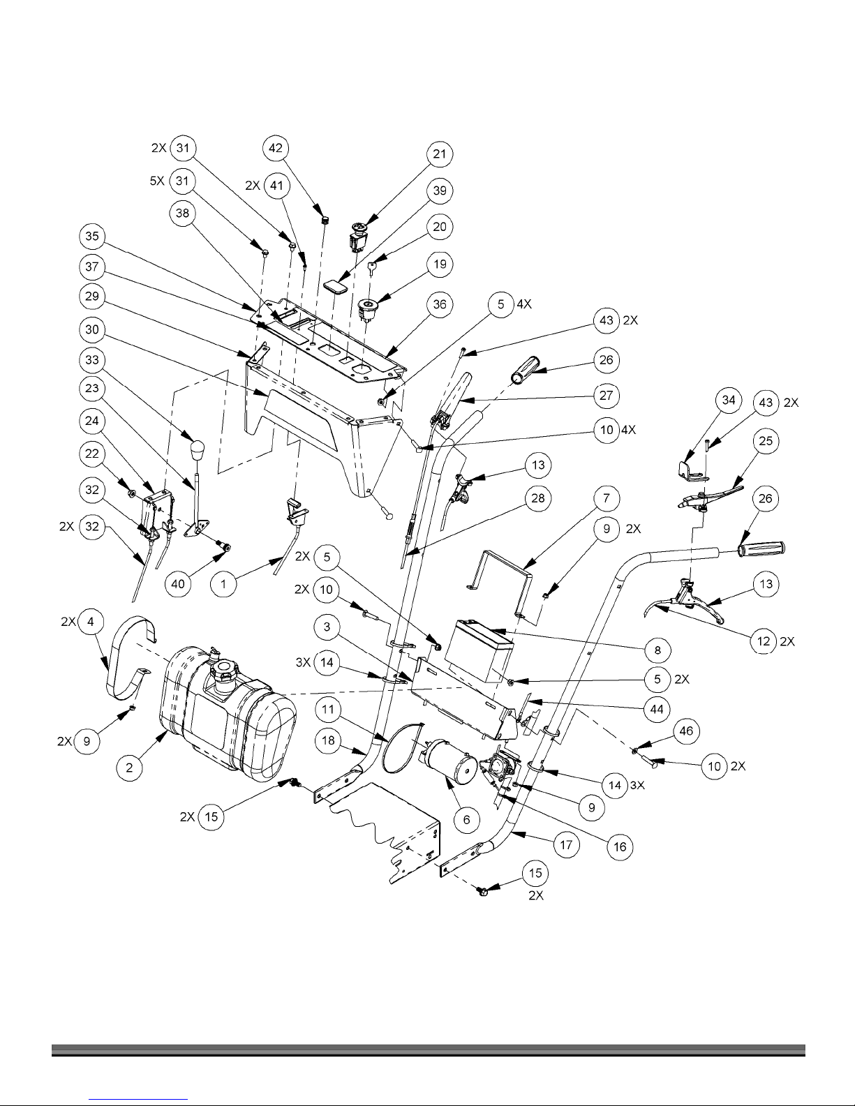
Schematic – Handlebar Assembly
CONTACT US AT www.DRpower.com 27

Parts List – Power Assembly
NOTE: Part numbers listed are available through DR Power Equipment.
Ref# Part# Description
Ref# Part# Description
1 35279 Frame w/Labels
2 35278 Label, SN and Address
3 34448 Engine, B&S, 20hp VTwin, ES, w/ Labels
and Horizontal Exhaust
37146 Engine, B&S, 16.5hp Pro Series, ES,
6pin, W/ Labels
37067 Engine, B&S, 14.5hp Intek, ES, 6Pin, w/
Labels
37068 Engine, B&S, 10.5hp Powerbilt, MS,
6Pin, w/ Labels
4 35280 Exhaust, B&S, 20hp, Horizontal
5 34130 Gasket, Exhaust, Briggs, 20hp VTwin
6 35056 Bolt, Muffler, B&S, 20hp
7 17912 Screw, 1/4-20 X .500", Tri-Lobe
8 34444 Guard, Exhaust, B&S V-Twin
9 36361 Ubolt, 1-1/8" ID, 1/4-20 x 1"
10 31283 Nut, Lock, 1/4-20, Serrated Flange
11 36356 Tansaxle, 3spd, W/ Switch, Peerless
12 33332 Nut, Nylon Lock, Flanged, 5/16-18
13 19289 Wheel, 18 X 6.5-8, Terrain, 5 Lug
14 16522 Nut, Lug, 1/2-20
15 34433 Hub, Wheel
16 34446 Caliper, Mechanical Disc with Pads
17 34437 Mount, Brake
18 34447 Rotor, 140mm
19 35272 Bolt, Torx BHCS, M5-0.8 X 10mm, Cl8.8,
ZP
20 11214 Cable Tie, 7-1/2" Long
21 35281 Bolt, Hex, Flange, Tri Lobe, 3/8-16 X
3/4", GR5 ZP
22 36359 Washer, Alignment, Female, M6
23 36358 Washer, Alignment, Male, M6
24 36360 Bolt, Alignment, M6-1 X 25, W/ Locking
Patch
25 33386 Clutch, Electric, 75 Ft-Lbs
26 36438 Harness, Safety, Neutral
27 34423 Pulley, Keyed, A V-Belt, 2.5" OD, 1" Shaft
28 15138 Pivot Washer, 1.375"ID, 2.0"OD
29 34430 Bracket, Axle Mount
30 34436 Pulley, Transaxle
31 11124 Snap Ring, External, 5/8"
32 24739 Idler Arm, Drive, FBP
33 15111 Bushing, 0.390" ID X 0.620" OD X 1.585" L
34 10850 Pulley, Flat Idler, 3"
35 33333 Nut, Nylon Lock, Flanged, 3/8-16
36 33348 Bolt, Hex, Flange, 3/8-16 X 2.5"
37 35110 Belt, AK32, 1/2" X 34"
38 35145 Bracket, Shift, Transmission
39 35111 Bracket, Rear, Transaxle
40 11173 Bolt, HCS, Serrated Flange, 5/16-18 X .50"
41 35137 Support, Frame, Rear, Peerless
42 15115 Washer, 1.38"ID 2.0"OD .5"L
43 15046 Pin, Detent, 1/4" X 2"
44 35303 Guide, Belt, Traction Drive
45 22252 Washer, Lock, 7/16", Split, ZP
46 19130 Washer, Flat, .469" X 1.62" X .25"
47 35318 Bolt, SH Countersink, 5/16-18 X 2", GR5, ZP,
Full Thread
48 35261 Spring, Extension
49 10119 Key, Square, 3/16" X 2"
50 12969 Shim, .75"ID, 1.125"OD, .06"L, ZP
51 11126 Ring, Retaining, 3/4" E-Clip
52 15712 Bolt, HCS, 3/8-16 X 2-1/4", GR5, ZP
53 37070 Key, Square, 1/4" X .75"
54 11238 Washer, Flat, 1/4"
55 11150 Bolt, SHCS, 1/4-18 X 3/4", Black Oxide
56 22324 Bolt, HCS, 7/16-20 x 2.75", GR8, ZP
57 35051 Spacer, Idler
28 DR
®
FIELD and BRUSH MOWER

Schematic – Drivetrain Assembly
CONTACT US AT www.DRpower.com 29

Parts List – Brush Deck Assembly
NOTE: Part numbers listed are available through DR Power Equipment.
Ref# Part# Description
Ref# Part# Description
1 33332 Nut, Nylon Lock, Flanged, 5/16-18
2 10913 Bolt, Carr, 5/16-18 X 1.5", ZP
3 35281 Bolt, Hex, Flange, Tri Lobe, 3/8-16 X
3/4", GR5 ZP
4 35134 Plate, Stud, Guard
5 35295 Brush Bar, 34"
35140 Brush Bar, 30"
34425 Brush Bar, 26"
6 36420 Skirt, Front, 34”
36419 Skirt, Front, 30”
36418 Skirt, Front, 26”
7 36342 Deck, 34" AT4 W/ Labels
36341 Deck, 30" AT4 W/ Labels
36340 Deck, 26" AT4 W/ Labels
8 13649 Label, Danger, Blade
9 36625 Label, Deck, 34"
36624 Label, Deck, 30"
36623 Label, Deck, 26"
10 35296 Blade, 34", Air Tip
11 34426 Pivot, Deck, Bracket
12 34438 Spindle, Assembly
13 35285 Belt, Brush Deck, Bk56, 5/8" X 58.8"
14 10177 Washer, Blade
15 16007 Nut, Nylon Lock, 5/8-18, GR2, ZP
16 34442 Idler Arm, Brush Deck
17 33333 Nut, Nylon Lock, Flanged, 3/8-16
18 15094 Spring E .750" OD X .112" Wire
19 35143 Bushing, Idler, Brush Deck
20 33348 Bolt, Hex, Flange, 3/8-16 X 2.5"
21 10189 Grease Fitting, 1/4-28, Straight
22 16445 Pulley, V, 8.5" OD 5l or B Belt
23 35288 Knob, 2.5", Stud, 3/8-16 X 3/4"
24 35291 Bracket, Deck, Stiffener, Right
25 35292 Bracket, Deck, Stiffener, Left
26 15072 Bushing 1.385" ID X 1.629" OD X 1.50" L
27 35301 Bolt, Carriage, 1/2-13 X 2", GR5, ZP
28 35141 Bolt, Hex, Flange, 3/8-16 X 3.5"
29 11914 Key, Square, 3/16 X .75"
30 15127 Pulley, Flat Idler, 4"
31 36339 Guard, Belt, AT4 W/ Labels
32 34140 Label, DR Logo, 4.0" Silver, 4 Color
33 22910 Nut, Finish, 1/2-13, GR5, ZP
34 35315 Guard, Deck, 34", Rubber
35133 Guard, Deck, 30", Rubber
35316 Guard, Deck, 26", Rubber
35 36614 Strap, Skirt, Mounting, 34"
36615 Strap, Skirt, Mounting, 30"
36616 Strap, Skirt, Mounting, 26"
36 36417 Guard, Debris, Deck
37 35051 Spacer, Idler
38 35033 Bolt, Carr, 5/16-18 X 1.75", GR5, ZP
30 DR
®
FIELD and BRUSH MOWER

Schematic – Brush Deck Assembly
CONTACT US AT www.DRpower.com 31
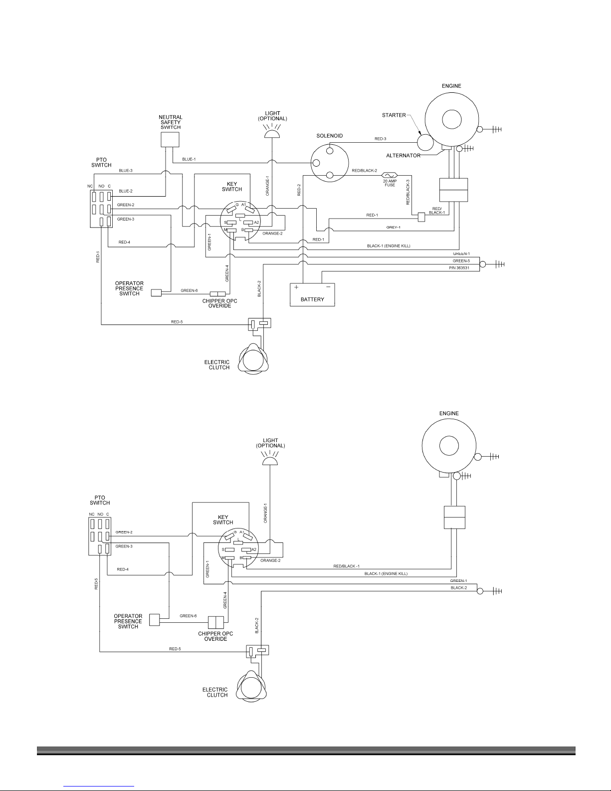
Wiring Diagram –Electric Start
Wiring Diagram –Manual Start
32 DR
®
FIELD and BRUSH MOWER

D
R
and
USH MOW
FIELD
BR
ER
2-Year Limited Warranty
Terms and Conditions
The DR FIELD and BRUSH MOWER is warranted for two (2) years against defects in materials or workmanship
when put to ordinary and normal consumer use; ninety (90) days for any other use.
For the purposes of all the above warranties, “ordinary and normal consumer use” refers to non-commercial
residential use and does not include misuse, accidents or damage due to inadequate maintenance.
®
DR Power Equipment certifies that the DR
product of this type is used. DR Power Equipment however, limits the implied warranties of merchantability and
fitness in duration to a period of two (2) years in consumer use, ninety (90) days for any other use.
The 2-Year Limited Warranty on the DR
factory. The 2-Year Limited Warranty is applicable only to the original owner.
The warranty holder is responsible for the performance of the required maintenance as defined by the manufacturer's
owner's manuals. The warranty holder is responsible for replacement of normally wearing parts such as the Drive
Belts, Blade, Filters, Spark Plug(s), Brake Components and Battery. Accessories to the machine are not covered by
this warranty.
During the warranty period, the warranty holder is responsible for the machine transportation charges, if required.
During the warranty period, warranty parts will be shipped by standard method at no charge to the warranty holder.
Expedited shipping of warranty parts is the responsibility of the warranty holder.
SOME STATES DO NOT ALLOW LIMITATIONS ON THE LENGTH OF IMPLIED WARRANTIES, SO THE ABOVE
LIMITATIONS MAY NOT APPLY TO YOU.
DR Power Equipment shall not be liable under any circumstances for any incidental or consequential damages or
expenses of any kind, including, but not limited to, cost of equipment rentals, loss of profit, or cost of hiring services
to perform tasks normally performed by the DR
SOME STATES DO NOT ALLOW THE EXCLUSION OR LIMITATION OF INCIDENTAL OR CONSEQUENTIAL
DAMAGES, SO THE ABOVE LIMITATIONS MAY NOT APPLY TO YOU.
FIELD and BRUSH MOWER is fit for ordinary purposes for which a
FIELD and BRUSH MOWER starts on the date the machine ships from our
FIELD and BRUSH MOWER.
THIS WARRANTY GIVES YOU SPECIFIC LEGAL RIGHTS, AND YOU ALSO HAVE OTHER RIGHTS, WHICH VARY
FROM STATE TO STATE.
CONTACT US AT www.DRpower.com 33

Warranty
CALIFORNIA EVAPORATIVE EMISSION CONTROL WARRANTY STATEMENT
YOUR WARRANTY RIGHTS AND OBLIGATIONS
The California Air Resources Board and Country Home Products, Inc. are pleased to explain the evaporative emission control
system warranty on your 2015 DR® Field and Brush Mower. In California, new equipment that use small off-road engines
must be designed, built and equipped to meet the State’s stringent anti-smog standards. Country Home Products, Inc. must
warrant the evaporative emission control system on your DR® Field and Brush Mower for the period of time listed below
provided there has been no abuse, neglect or improper maintenance of your equipment.
Your evaporative emission control system may include parts such as the carburetor, fuel-injection system, the ignition
system, catalytic converter, fuel tanks, fuel lines, fuel caps, valves, canisters, filters, vapor hoses, clamps, connectors, and
other associated emission-related components.
MANUFACTURER’S WARRANTY COVERAGE:
This evaporative emission control system is warranted for two years. If any evaporative emission-related part on your
equipment is defective, the part will be repaired or replaced by Country Home Products, Inc.
OWNER’S WARRANTY RESPONSIBILITIES:
As the DR® Field and Brush Mower owner, you are responsible for performance of the required maintenance listed in your
owner’s manual. Country Home Products, Inc. recommends that you retain all receipts covering maintenance on your DR®
Field and Brush Mower, but Country Home Products, Inc. cannot deny warranty solely for the lack of receipts.
As the DR® Field and Brush Mower owner, you should however be aware that Country Home Products, Inc. may deny you
warranty coverage if your DR® Field and Brush Mower or a part has failed due to abuse, neglect, or improper maintenance or
unapproved modifications.
You are responsible for presenting your DR® Field and Brush Mower to Country Home Products, Inc.’s distribution center or
service center as soon as the problem exists. The warranty repairs should be completed in a reasonable amount of time, not
to exceed 30 days. If you have a question regarding your warranty coverage, you should contact the Country Home Products,
Inc. Technical Service Department by dialing our TOLL-FREE Hotline at 1-800-DR-OWNER (376-9637).
GENERAL EMISSIONS WARRANTY COVERAGE:
Country Home Products, Inc. warrants to the ultimate purchaser and each subsequent purchaser that the DR® Field and
Brush Mower is:
(1) Designed, built and equipped so as to conform with all applicable regulations; and
(2) Free from defects in materials and workmanship that cause the failure of a warranted part to be identical in all material
respects to that part as described in Country Home Products, Inc.’s application for certification.
The warranty period begins on the date the DR® Field and Brush Mower is delivered to an ultimate purchaser. The warranty
period is two years.
Subject to certain conditions and exclusions as stated below, the warranty on emission-related parts is as follows:
(1) Any warranted part that is not scheduled for replacement as required maintenance in the written instructions supplied, is
warranted for the warranty period stated above. If the part fails during the period of warranty coverage, the part will be
repaired or replaced by Country Home Products, Inc. according to subsection (4) below. Any such part repaired or replaced
under warranty will be warranted for the remainder of the period.
34 DR
®
FIELD and BRUSH MOWER

(2) Any warranted part that is scheduled only for regular inspection in the written instructions supplied is warranted for the
warranty period stated above. Any such part repaired or replaced under warranty will be warranted for the remaining warranty
period.
(3) Any warranted part that is scheduled for replacement as required maintenance in the written instructions supplied is
warranted for the period of time before the first scheduled replacement date for that part. If the part fails before the first
scheduled replacement, the part will be repaired or replaced by Country Home Products, Inc. according to subsection (4)
below. Any such part repaired or replaced under warranty will be warranted for the remainder of the period prior to the first
scheduled replacement point for the part.
(4) Repair or replacement of any warranted part under the warranty provisions herein must be performed at a warranty station
at no charge to the owner.
(5) Notwithstanding the provisions herein, warranty services or repairs will be provided at all of our distribution centers that
are franchised to service the subject engines or equipment.
(6) The DR® Field and Brush Mower owner will not be charged for diagnostic labor that is directly associated with diagnosis
of a defective, emission-related warranted part, provided that such diagnostic work is performed at a warranty station.
(7) Country Home Products, Inc. is liable for damages to other engine or equipment components proximately caused by a
failure under warranty of any warranted part.
(8) Throughout the DR® Field and Brush Mower warranty period stated above, Country Home Products, Inc. will maintain a
supply of warranted parts sufficient to meet the expected demand for such parts.
(9) Any replacement part may be used in the performance of any warranty maintenance or repairs and must be provided
without charge to the owner. Such use will not reduce the warranty obligations of Country Home Products, Inc.
(10) Add-on or modified parts that are not exempted by the Air Resources Board may not be used. The use of any nonexempted add-on or modified parts by the ultimate purchaser will be grounds for disallowing a warranty claims. Country
Home Products, Inc. will not be liable to warrant failures of warranted parts caused by the use of a non-exempted add-on or
modified part.
WARRANTED PARTS:
The repair or replacement of any warranted part otherwise eligible for warranty coverage may be excluded from such warranty
coverage if COUNTRY HOME PRODUCTS, Inc. demonstrates that the DR® Field and Brush Mower has been abused,
neglected, or improperly maintained, and that such abuse, neglect, or improper maintenance was the direct cause of the need
for repair or replacement of the part. That notwithstanding, any adjustment of a component that has a factory installed, and
properly operating, adjustment limiting device is still eligible for warranty coverage. The following emission warranty parts list
are covered (use portions of this list applicable to your DR® Field and Brush Mower:
(1) Fuel Tank
(2) Fuel Cap
(3) Fuel Line
(4) Fuel Line Fittings
(5) Fuel Line Clamps
(7) Control Valve
(14) Vapor Hoses
(15) Liquid/Vapor Separator
(16) Carbon Canister
(17) Canister Mounting Brackets
(18) Carburetor Purge Port Connector
If you have any questions, please contact us at www.DRpower.com or call 1-800-DR-OWNER (376-9637)
CONTACT US AT www.DRpower.com 35

Daily Checklist for the DR FIELD and BRUSH MOWER
To help maintain your DR FIELD and BRUSH MOWER for optimum performance, we recommend you follow this checklist
each time you use your machine.
Before performing any maintenance procedure or inspection, stop the engine, wait five (5) minutes to allow all parts to cool.
Disconnect the spark plug wire(s), keeping it away from the spark plug(s).
[ ] Check the engine oil level.
[ ] Check the gas Level
[ ] Check the general condition of the Mower, e.g.; nuts, bolts, welds, etc.
[ ] Check Tire Pressure
[ ] Check belts for wear, proper alignment and tension.
[ ] Check the blade for tightness, nicks and wear. Remove any wrapped weeds and grass from the Blade Bearing Housing to
prevent buildup.
[ ] Check that the engine air cooling system is clean of debris.
Before performing any maintenance procedure or inspection, stop the engine, wait five (5) minutes to allow all parts to coo and
disconnect spark plug
End of Season and Storage
Note: Please refer to the Engine Owner's Manual for engine-specific procedures.
Change the oil (and oil filter, if applicable). For winter use, use SAE 5W – 30 HD.
Remove the Spark Plug(s) and pour about 1 ounce of motor oil into the Cylinder hole. Replace the Plug(s) and crank the
Engine a couple of times. This will coat the piston(s) and seat the valves to prevent moisture buildup.
Clean/replace the Air Filters.
Clean dirt and debris from the Cylinder Head Cooling Fins, Blower Housing, Debris Screen, and Muffler area of the
Engine.
If your Engine has a Fuel Filter, replace it.
If your DR FIELD and BRUSH MOWER will be idle for more than 30 days, we recommend using a gas stabilizer. This will
prevent sediment from gumming up the Carburetor. If there is dirt or moisture in the gas or Tank, remove it by draining
the Tank. Completely fill the Tank with fresh, unleaded gas and add the appropriate amount of stabilizer or gasoline
additive. Run the Engine for a short time to allow the additive to circulate. Close the Fuel Shut-Off Valve, if your machine
is equipped with one, to prevent Carburetor overflow and leakage.
Store the Battery in a dry area that will not freeze. If you will not use the machine over a long period, charge the Battery
every four to six weeks. See page 22.
Remove any wrapped weeds from the Blade Bearing Housing. Clean grass and debris from the top and underneath the
Mower Deck with a stiff brush.
Check the Blade for nicks and wear. Remove the Blade and sharpen, or have it professionally sharpened if needed.
Perform the lubrication as outlined starting on page 17.
Note: For winter use, please refer to the attachment instructions.
75 MEIGS ROAD, P.O. BOX 25, VERGENNES, VERMONT 05491
©2016 Country Home Products, Inc. All rights reserved 366601A
 Loading...