

Page 1

`
DR
SAFETY & OPERATING INSTRUCTIONS
®
CHIPPER/SHREDDER
DR Power Equipment
Serial No.
Order No.
Read and understand this manual and all instructions before operating the DR CHIPPER/SHREDDER.
Original Language
Toll-free phone: 1-800-DR-OWNER (376-9637)
Fax: 1-802-877-1213
Website: www.DRpower.com
Page 2

Table of Contents
Chapter 1: General Safety Rules ............................................................................................................................................................ 3
Chapter 2: Setting Up The DR CHIPPER/SHREDDER ......................................................................................................................... 7
Chapter 3: Operating The DR CHIPPER/SHREDDER ......................................................................................................................... 10
Chapter 4: Maintaining The DR CHIPPER/SHREDDER ...................................................................................................................... 14
Chapter 5: Troubleshooting .................................................................................................................................................................. 21
Chapter 6: Parts Lists and Schematic Diagrams .................................................................................................................................. 24
Conventions used in this manual
This indicates a hazardous situation, which, if not followed, will result in death or serious injury.
This indicates a hazardous situation, which, if not avoided, could result in death or serious injury.
This indicates a hazardous situation, which, if not avoided, could result in minor or moderate injury.
This information is important in the proper use of your machine. Failure to follow this instruction could result in damage to
your machine or property.
Serial Number and Order Number
A Serial Number is used to identify your machine and is located on the Serial Number Label on your machine. An Order Number
is used to check and maintain your order history and is located on the upper left portion of your packing slip. For your
convenience and ready reference, enter the Serial Number and Order Number in the space provided on the front cover of this
manual.
Additional Information and Potential Changes
DR Power Equipment reserves the right to discontinue, change, and improve its products at any time without notice or obligation
to the purchaser. The descriptions and specifications contained in this manual were in effect at printing. Equipment described
within this manual may be optional. Some illustrations may not be applicable to your machine.
2 DR
®
CHIPPER/SHREDDER
Page 3
Chapter 1: General Safety Rules
#
#
#
#
#
Read this Safety & Operating Instructions Manual before you use the DR CHIPPER/SHREDDER. Become familiar with the
operation and service recommendations to ensure the best performance from your machine. If you have any questions or need
assistance, please contact us at www.DRpower.com or call Toll-Free 1-800-DR-OWNER (376-9637) and one of our Technical
Support Representatives will be happy to help you.
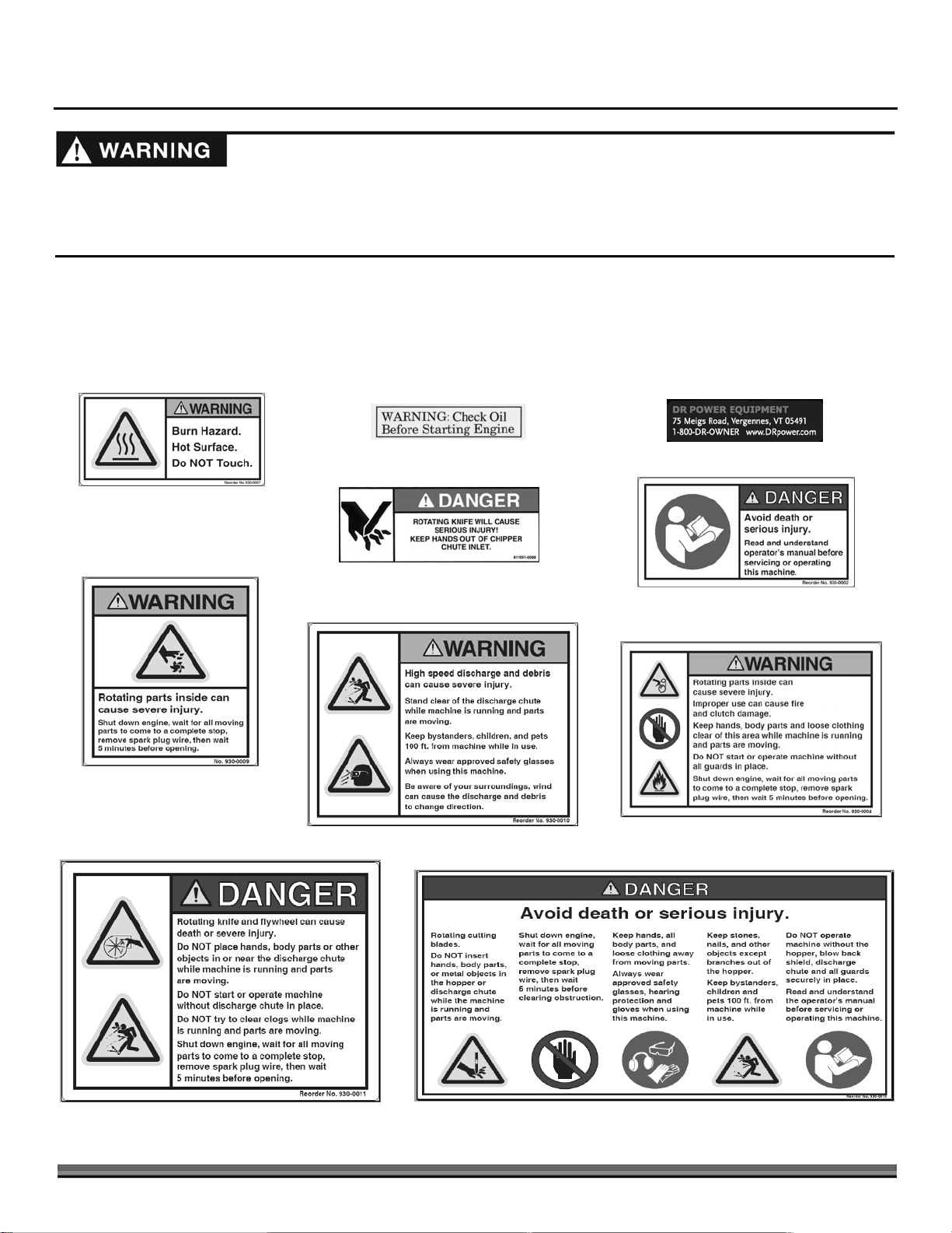
Labels
Your DR CHIPPER/SHREDDER carries prominent labels as reminders for its proper and safe use. Shown below are copies of all
the Safety and Information labels that appear on the equipment. Take a moment to study them and make a note of their location
on your CHIPPER/SHREDDER as you set up and before you operate the unit. Replace damaged or missing Safety and
Information labels immediately.
#241991
#137581
227141
241831
#235451
241801
#241821
241811
247961
CONTACT US AT www.DRpower.com 3
Page 4

Protecting Yourself and Those Around You
This is a high-powered machine, with moving parts operating with high energy. You must operate the machine safely. Unsafe
operation can create a number of hazards for you, as well as anyone else in the nearby area. This machine can crush, grind, cut,
and sever parts of your body if they enter the inlet or discharge area of your CHIPPER/SHREDDER. Always take the following
precautions when using this machine:
Keep in mind that the operator or user is responsible for accidents or hazards occurring to other people, their property, and
themselves.
Always wear protective goggles or safety glasses with side shields while using the CHIPPER/SHREDDER to protect your eyes
from possible thrown debris.
Avoid wearing loose clothing or jewelry, which can catch on moving parts or the material fed into the CHIPPER/SHREDDER.
We recommend wearing gloves while using the CHIPPER/SHREDDER. Be sure your gloves fit properly and do not have loose
cuffs or drawstrings.
Wear shoes with non-slip treads when using your CHIPPER/SHREDDER. If you have safety shoes, we recommend wearing
them. Do not use the machine while barefoot or wearing open sandals.
Wear long pants while operating the CHIPPER/SHREDDER.
Use ear protectors or earplugs rated for at least 20 dba to protect your hearing.
Keep bystanders at least 100 feet away from your work area. Stop the engine when another person or pet approaches.
Safety for Children and Pets
Tragic accidents can occur if the operator is not alert to the presence of children and pets. Children are often attracted to the
machine and the chipping/shredding activity.
these precautions:
Never
assume that children will remain where you last saw them. Always follow
Keep children and pets at least 100 feet from the working area and ensure they are under the watchful care of a responsible
adult.
Be alert and turn the machine off if children or pets enter the work area.
Never allow children to operate the CHIPPER/SHREDDER.
4 DR
®
CHIPPER/SHREDDER
Page 5

Safety with Gasoline - Powered Machines
Gasoline is a highly flammable liquid. Gasoline also gives off flammable vapor that can be easily ignited and cause a fire or
explosion. Never overlook the hazards of gasoline. Always follow these precautions:
Never run the Engine in an enclosed area or without proper ventilation as the exhaust from the Engine contains carbon
monoxide, which is an odorless, tasteless, and deadly poisonous gas.
Store all fuel and oil in containers specifically designed and approved for this purpose and keep away from heat and open
flame, and out of the reach of children.
Replace rubber Fuel Lines and Grommets when worn or damaged and after 5 years of use.
Fill the Gasoline Tank outdoors with the Engine off and allow the Engine to cool completely. Don't handle gasoline if you or
anyone nearby is smoking, or if you're near anything that could cause it to ignite or explode. Reinstall the Fuel Tank Cap and
Fuel Container Cap securely.
If you spill gasoline, do not attempt to start the Engine. Move the machine away from the area of the spill and avoid creating
any source of ignition until the gas vapors have dissipated. Wipe up any spilled fuel to prevent a fire hazard and properly
dispose of the waste.
Allow the Engine to cool completely before storing in any enclosure. Never store a machine that has gas in the tank, or a Fuel
Container, near an open flame or spark such as a water heater, space heater, clothes dryer or furnace.
Never make adjustments or repairs with the Engine running. Shut down the Engine, disconnect the Spark Plug wire, keeping
it away from the Spark Plug to prevent accidental starting, wait 5 minutes before making adjustments or repairs.
Never tamper with the Engine’s Governor setting. The Governor controls the maximum safe operation speed and protects
the Engine. Over-speeding the Engine is dangerous and will cause damage to the Engine and to the other moving parts of the
machine. If required, see your authorized dealer for Engine governor adjustments.
Keep combustible substances away from the Engine when it is hot.
Never cover the machine while the Muffler is still hot.
Do not operate the Engine with the Air Cleaner or the Carburetor Air Intake Cover removed. Removal of such parts could
create a fire hazard. Do not use flammable solutions to clean the Air Filter.
The Muffler and Engine become very hot and can cause a severe burn; do not touch.
General Safety
Operating this CHIPPER/SHREDDER safely is necessary to prevent or minimize the risk of death or serious injury. Unsafe
operation can create a number of hazards for you. Always take the following precautions when operating this machine:
Your CHIPPER/SHREDDER is a powerful tool, not a plaything. Exercise extreme caution at all times. The machine is
designed to chip wood and shred most organic materials. Do not use it for any other purpose.
Thoroughly inspect the area in which you will be working and remove all foreign objects. Look for rope, wire, etc., and remove
these objects before chipping/shredding. Inserting these objects into the CHIPPER/SHREDDER Hopper could damage the
machine and/or cause injury.
Know how to stop the CHIPPER/SHREDDER quickly; see “Stopping the Engine” in Chapter 3.
Never operate your unit on a slippery, wet, muddy, or icy surface. Exercise caution to avoid slipping or falling.
See manufacturer’s instructions for proper operation and installation of accessories. Only use accessories approved by DR
Power Equipment.
Never use the machine without ensuring that all guards and shields are in place.
Never, under any conditions, remove, bend, cut, fit, weld, or otherwise alter standard parts on the CHIPPER/SHREDDER.
This includes all shields and guards. Modifications to your machine could cause personal injuries and property damage and
will void your warranty.
Never use the machine with the Hopper(s) or Discharge Chute removed.
CONTACT US AT www.DRpower.com 5
Page 6

General Safety (continued)
Never place any part of your body in the CHIPPER/SHREDDER Hopper(s), discharge opening, or near any moving part while
the machine is running. Keep the area of discharge clear of anything that will obstruct a clear discharge. Wind can also
change discharge direction, so be aware. If it becomes necessary to push material into the CHIPPER/SHREDDER Hopper(s),
use a small diameter stick, NOT WITH YOUR HANDS.
Keep your face and body back from the CHIPPER/SHREDDER Hopper(s) to avoid accidental bounce back of any material.
Do not allow an accumulation of processed material to build up in the discharge area as this will prevent proper discharge
and can result in kickback from the CHIPPER/SHREDDER Hopper(s).
Allow only one person to operate the CHIPPER/SHREDDER at any time.
Always operate the machine from the Operator Zone (see Figure 10
of the machine when the Engine is running or the Rotor is turning.
If the machine should start making an unusual noise or vibration, shut down the Engine, disconnect the Spark Plug Wire,
keeping it away from the Spark Plug to prevent accidental starting, wait 5 minutes, then inspect for damage. Vibration is
generally a warning of trouble. Check for damaged parts and clean, repair, and/or replace as necessary.
Never tamper with safety devices. Check their proper operation regularly.
Never try to pick up, move, or transport the machine while the Engine is running or the Rotor is turning.
Before performing any maintenance or inspection procedure on the CHIPPER/SHREDDER, shut the Engine OFF, remove the
Spark Plug Wire, and keep it away from the Spark Plug.
Never allow people who do not understand and/or have not read this Safety and Operating Instructions Manual to use the
CHIPPER/SHREDDER. Allow only responsible individuals who are familiar with these rules of safe operation to use your
machine.
Never overload or attempt to Chip or Shred material beyond the manufacturer’s recommendation. Personal injury or damage
to the machine could result.
While using the CHIPPER/SHREDDER, don't hurry or take things for granted. When in doubt about the equipment or your
surroundings, stop the machine and take the time to look things over.
Never operate the machine when under the influence of alcohol, drugs, or medication.
Use the machine only in daylight.
Stay alert for hidden hazards or traffic.
Keep all nuts and bolts tight and keep the equipment in good operating condition.
on page 13). Never pass or stand on the discharge side
A Note to All Users
Under California law, and the laws of some other states, you are not permitted to operate an internal combustion engine using
hydrocarbon fuels without an Engine Spark Arrester. This also applies to operation on US Forest Lands. All DR
CHIPPER/SHREDDERS shipped to California, New Mexico, and Washington State are provided with Spark Arresters. Failure of
the owner or operator to maintain this equipment in compliance with state regulations is a misdemeanor under California law and
may be in violation of other state and/or federal regulations. Contact your State Park Association or the appropriate state
organization for specific information in your area.
No list of warnings and cautions can be all-inclusive. If situations occur that are not covered by this manual, the operator must
apply common sense and operate this DR CHIPPER/SHREDDER in a safe manner. Contact us at www.DRpower.com or call Toll
Free: 1-800-DR-OWNER (376-9637) for assistance.
6 DR
®
CHIPPER/SHREDDER
Page 7
Chapter 2: Setting Up The DR CHIPPER/SHREDDER
l
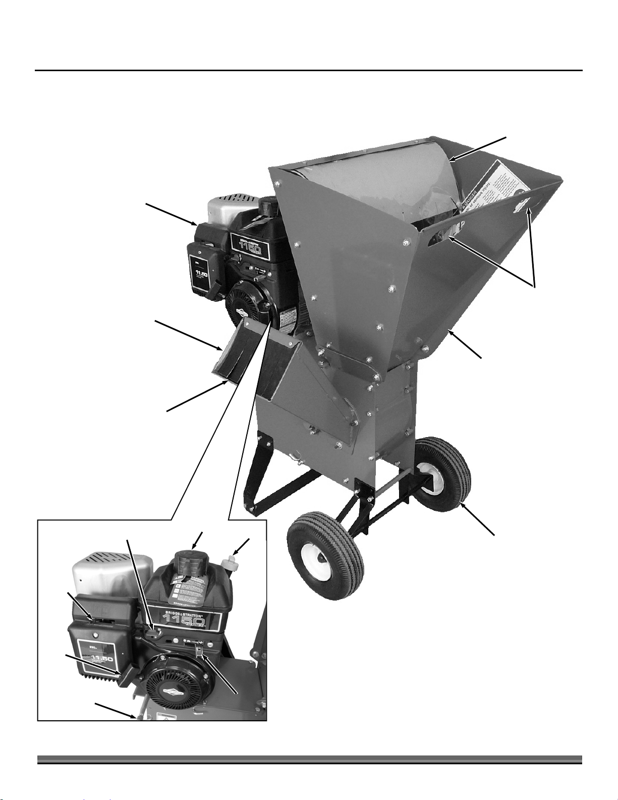
It may be helpful to familiarize yourself with the controls and features of your DR CHIPPER/SHREDDER as shown in Figure 1
before beginning these procedures. If you have any questions at all, please feel free to contact us at www.DRpower.com.
DR CHIPPER/SHREDDER Controls and Features
Blowback Shield
11.50 FT-LBS Torque
Briggs & Stratton Engine
Transport
Chipper Hopper
Handles
Choke
Control
Lever
Recoil
Starter
Handle
Blowback Shield
Fuel Shut-Off Valve
Fuel Fill
OilFil
Shredder Hopper
Pneumatic
Tires
Oil Drain
Throttle
Figure 1
CONTACT US AT www.DRpower.com 7
Page 8
Specifications
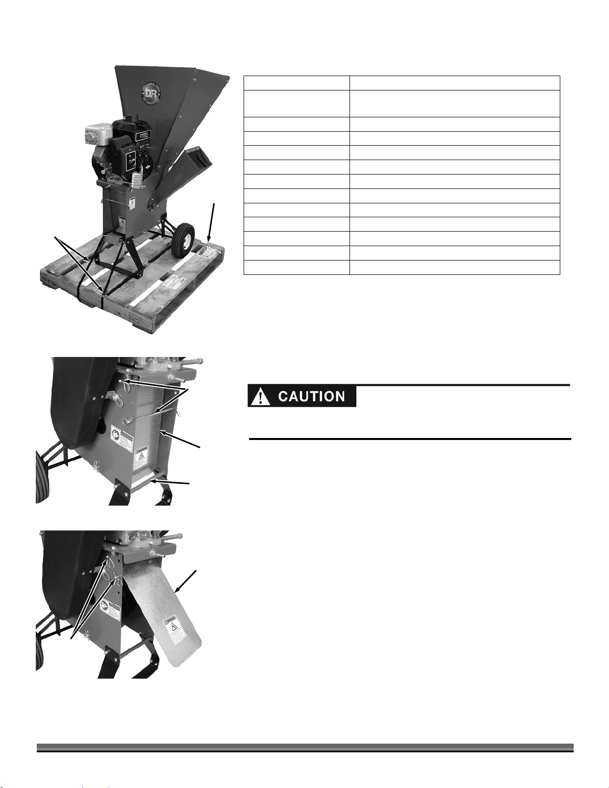
Straps
Figure 2
Pallet
Engine
11.50 FT-LBS Torque Briggs & Stratton
Please refer to the Engine Owner’s Manual for
Engine-specifications.
Tire Size
Clutch
Engagement speed
Frame
Belt
Size
Construction
Machine Dimensions
Operating Weight
Shipping Weight
Shipping Dimensions
10 inch diameter
Centrifugal
1,000 RPM (the Rotor will turn at idle)
Welded 12 gauge steel construction
V-Belt
44 inches
Wrapped for abrasion resistance
56" L x 41" W x 44" H
185 pounds
215 pounds
40" L x 34" W x 57" H
Unpacking the DR CHIPPER/SHREDDER
Tools and supplies needed:
Hammer
Pry Bar
Wire Cutters or Utility Knife
Gloves & Safety Glasses
Figure 3
Baffle Rods
and
Cotter Pins
Baffle Rods
and
Cotter Pins
Baffle
Plate
Pipe
Spacer
Baffle
Plate
Wear Safety Glasses to protect your eyes from flying debris and Gloves to
protect your hands from sharp objects when performing these procedures.
1. Use a Hammer and Pry Bar to separate the bottom Crate Boards from the
Pallet and lift the Crate off the Pallet.
2. Cut the Straps that are securing the machine to the Pallet (Figure 2).
3. Use the Hand Slots in the Shredder Hopper to tilt and roll the machine from
the Pallet.
4. Remove the two Baffle Rods and Cotter Pins that go through the top of the
Baffle Plate and the one behind it (Figure 3).
5. Move the bottom of the Baffle Plate to the outside of the Pipe Spacer and
reinstall the top portion of the Plate using the Baffle Rod and Cotter Pin
(Figure 4).
6. Reinstall the Baffle Rod and Cotter Pin to hold the Baffle Plate up in the
discharge position. Which holes you use depends on the discharge angle
desired when chipping/shredding.
If there are any questions contact us at www.DRpower.com or call 1-800-DROWNER (376-9637). Do not discard the shipping materials until you are fully
satisfied with your new DR CHIPPER/SHREDDER.
Figure 4
8 DR
®
CHIPPER/SHREDDER
Page 9

Adding Oil and Gasoline
l
You MUST add oil before starting the Engine. This machine is shipped without oil. Traces of oil may be in the reservoir from
factory testing, but you MUST add oil before starting the Engine
avoid overfilling.
To get an accurate reading when checking the oil level:
- The Engine MUST
- Refer to the Engine Manual for detailed information before performing the following procedures.
be level.
. Fill the reservoir slowly, checking the level frequently to
Engine Oil
Fuel
NOTE: Use only the recommended high detergent Engine oil. Other types of oil
could cause problems operating your machine. Please refer to your Engine Owner’s
Manual for more detailed oil information.
1. Position the machine so the Engine is level. Remove the Oil Fill/Dipstick
(Figure 5).
2. Initially add 16 oz. of the oil recommended by the Engine Manufacturer.
Wait one minute for the oil to settle.
3. Check the Oil level on the Dipstick as described in the Engine Manual.
4. Continue adding a few ounces of oil at a time, rechecking the level until the
oil reaches the full level as indicated in the Engine Manual. Be careful not to
overfill.
5. Replace the Oil Fill/Dipstick when full.
6. Remove the Fuel Fill Cap and fill the Fuel Tank with fresh, unleaded gas (with a minimum of 85 Octane) to approximately 1" to
1-1/2" below the top of the Fill Neck to allow for Fuel expansion (Figure 8). Be careful not to overfill and reinstall the Fuel Fill
Cap before starting the Engine. See your Engine Owner’s Manual for more detailed information.
NOTE: To refill the Fuel Tank, turn the Engine OFF, and let the Engine cool at least five minutes before removing the Fuel Fill Cap.
SAE 30: above 50 degrees F; 10w-30: 10-90 degrees F; 5w-30:
30 degrees F or below
Unleaded gasoline
Figure 5
Fuel Fill
Oil
Fill/Dipstick
Fuel Fil
Check the Tire Pressure
Tools Needed:
Tire Pressure Gauge
Air Compressor or Hand Pump
1. Remove the Valve Stem Protective Cap (Figure 6) and check the Tire
pressure with a Tire Pressure Gauge.
2. Check the manufacturers recommended pressure that is stamped on the
side of the Tire.
Do not over inflate the Tires. Inflate to the manufacturers recommended
pressure.
3. If the pressure is too low, add air through the Valve Stem with an Air
Compressor or Hand Pump.
4. Replace the Valve Stem Protective Cap when finished.
Valve Stem
Protective Cap
Figure 6
CONTACT US AT www.DRpower.com 9
Page 10
Chapter 3: Operating The DR CHIPPER/SHREDDER
A
This chapter covers the procedures for starting and stopping your new DR CHIPPER/SHREDDER and discusses basic operation
features. It may be helpful to better familiarize yourself with the features of your CHIPPER/SHREDDER by reviewing Figure 1 in
Chapter 2 before beginning the steps outlined in this chapter.
Read and understand the warnings listed in “Chapter 1 General Safety Rules” before operating this CHIPPER/SHREDDER.
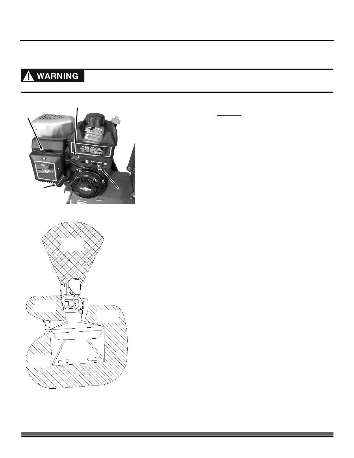
Choke
Control
Lever
Recoil
Starter
Handle
Figure 7
Fuel Shut-Off Valve
Discharge
rea
Throttle
Starting the Engine
1. Check the Oil and Fuel level every time you use the DR
CHIPPER/SHREDDER.
2. Turn the Fuel Shut-Off Valve to the OPEN position (Figure 7).
3. Check Inlet Hoppers and Discharge Chute and remove any debris buildup
from the machine by first unplugging the Spark Plug Wire and following the
instructions on page 16.
4. Move the Choke Control Lever to the right to the Choke position (leave in the
Run position to the left if the Engine is already warm).
5. Move the Throttle to the right, FAST (Rabbit) position.
6. Grasp the Recoil Starter Handle and slowly pull until you feel resistance,
then pull the cord rapidly to start the Engine. One or two pulls will usually
start the DR CHIPPER/SHREDDER.
6. As the Engine warms up, slowly adjust the Choke to the left towards the Run
position. Wait until the Engine runs smoothly before each Choke
adjustment.
7. When the Engine is warmed up and running smoothly, ensure that the Choke
is fully in the Run position to the left.
NOTE: The Throttle should always be fully to the right when Chipping/Shredding.
Operator
Zone
Chipper
Hopper
Operator
Zone
Figure 8
the machine.
10 DR
Shredder
Hopper
®
CHIPPER/SHREDDER
Operator
Zone
Stopping the Engine
Move the Throttle Control Lever all the way to the left past the SLOW (Turtle)
position to the “STOP” position (Figure 7).
NOTE: Close the Fuel Shut-Off Valve when transporting or storing the DR
CHIPPER/SHREDDER.
Before You Begin
Visually check the Chipper Knife for damage each time you use the machine.
NOTE:
Check for shaft movement while starting the Engine. If the shaft does not
turn, STOP the Engine and clean out the Chipper/Shredder Hopper(s) as instructed
on page 16.
ALWAYS operate the DR CHIPPER/SHREDDER from the Operator Zones
(Figure 8).
When viewed from the Chipper Hopper side the Rotor turns in a clockwise
direction.
NEVER assume you know where the Chipper Knife is. You do not know where
it is.
ALWAYS stop the Engine when leaving the Operating Zone or when moving
Page 11

Processing Material
Read and understand the warnings listed in “Chapter 1 General Safety Rules” before operating this CHIPPER/SHREDDER.
Your DR CHIPPER/SHREDDER can process dry or green material.
Green material will process quicker and easier than dry material.
Soft wood processes easier than hard wood.
Your operator experience will teach you how different materials chip/shred and how fast you can process different materials.
Most materials process well with the standard screen provided with the DR CHIPPER/SHREDDER.
It is best to trim off any side twigs from the main branch that you are chipping.
When chipping branches, sometimes a tail will remain at the end of a branch. To avoid this, rotate the branch while feeding it
into the Chipper Hopper. Rotating the branch as you feed it into the machine will improve chipping performance.
Use caution with small diameter green saplings and branches less than 1" in diameter. Chip these grouped or bundled together
to provide support for each other. If the material is 1" or larger, feed only one at a time into the Chipper Hopper.
Make sure the DR CHIPPER/SHREDDER finishes processing material in the Hopper(s) before shutting the Engine off.
Using the Chipper Hopper
The Chipper Hopper is mounted on the side of the machine and is designed to chip the larger, heavier materials that the Shredder
Hopper isn’t designed to handle. The revolving Chipper Knife mounted on a Rotor turns branches fed into the Hopper into
“chips”. The Chipper can chip twigs and branches ranging in size from 1" to 2-1/2" in diameter. Cut your materials into
manageable lengths of no more than five or six feet long
before feeding them into the Chipper Hopper.
The Chipper Hopper must be securely bolted to the side of your DR CHIPPER/SHREDDER before using the machine!
Feed the branch into Chipper Hopper keeping the branch at the same angle as the Chipper Hopper.
As the branch becomes short and is at the outside edge of the Chipper Hopper, finish processing it by pushing it in with the
next branch.
Do not force material into the Chipper. If the machine does not chip well, the Chipper Knife may need sharpening or to be
replaced.
Extremely hard knots will not process very well. Push any short stubs that have not self-fed through the Chipper, with the next
branch to be chipped.
Never throw remaining stubs or knots into the Shredder Hopper; damage will result.
Overloading the Chipper Hopper will cause the rotor speed to decrease. If you hear the Engine RPM decreasing, stop feeding
material into the Chipper Hopper until the Engine has returned to full speed.
NEVER allow processed material to build up within 3" of the Discharge opening. Move the DR CHIPPER/SHREDDER or the
pile as needed. Failure to do so could result in unnecessary jamming of the machine.
To move a pile of processed material, first shut off the Engine, and use a spade, rake, or long handle tool; NEVER
hands or feet!
If you jam the machine and do not stop the Engine, it can damage the machine. This damage can be costly and not covered
under warranty. See “To Free a Jammed Flywheel” on page 16.
use your
CONTACT US AT www.DRpower.com 11
Page 12

Using the Shredder Hopper
The Shredder Hopper is located on the top of the DR CHIPPER/SHREDDER and is the opening into which all materials to be
shredded should be fed. You can shred most organic materials. A flex guard, or blowback shield is attached to the Hopper. You
must push material past this flap using a wooden stick in order to enter the main Shredding Chamber where revolving steel
Hammers do the shredding.
The Blowback Shield is an important feature; it prevents kickback of materials! Do not use your machine unless the Blowback
Shield is securely fastened in place.
Due to the wide variety of materials that you can shred, and their very different physical characteristics, only feed limited
quantities of any material into the Shredder Hopper at first. Increase the amount and length of material if you find that the
material is processing without any difficulty. Your judgment and operator experience is very important. Be sure not to overload
the machine by feeding too much material into the Hopper at one time. If you hear the speed of the Engine decreasing, stop
feeding material into the machine at once. Do not resume feeding the machine until the Engine has returned to full speed.
The maximum diameter of material that you can shred is 3/8". Feed any larger material through the Chipper Hopper. Material
larger than 3/8" can cause serious damage to any of the internal parts of the Shredding Chamber. Inspect the DR
CHIPPER/SHREDDER after every use for bent Hammers, missing Spacers, clogging, or damage to the Screen or any other
obvious problems. If damage occurs, the Rotor Assembly can become unbalanced causing excessive vibration. If used in this
condition, damage can occur. Do not use the machine if vibration is present. Vibration is generally a warning sign of trouble.
You can feed several small branches into the Shredder Hopper at once providing their combined diameter is less than 3/8".
Cut branches longer than three (3) feet to make them more manageable. Allow green materials to dry, or process in small
batches with dry materials to avoid winding around the Rotor Assembly.
Wet materials will clog the machine easily. If clogging occurs, stop the Engine; remove the screen and process material without
it. Processing in this way will reduce the amount of reduction, but will reduce clogging.
MATERIALS BEST SUITED FOR SHREDDING
Leaves Flowers Corn Stalks Roots
Soil Palm frond tops Grass clippings Garden debris
Potato vines Straw and Hay Hedge clippings Tomato vines
Manure Kitchen Waste Small branches
The Hammers within the Shredding Chamber can tug suddenly at material fed into the Shredder Hopper. Do not hold on tightly
to branches and vines, and do not feed material straight down into the Hopper with your arm pointing downward toward the
opening. Instead, keep your arms parallel to the ground and several inches above the top edge of the Hopper.
12 DR
®
CHIPPER/SHREDDER
Page 13

To Free a Jammed Rotor
A
Before performing any maintenance procedure or inspection, stop the Engine,
wait five (5) minutes to allow all moving parts to come to a complete stop
and cool. Disconnect the Spark Plug Wire, keeping it away from the Spark
Plug.
Baffle
Plate
1. Remove any material left in the Chipper and Shredder Hoppers with a
wooden stick.
2. Check the Discharge Opening for clogs. If it is clogged, clear it with a stick.
3. Also, with a stick, loosen and remove any material left in the
Chipping/Shredding Chamber.
4. Start the machine and allow any remaining material in the
Chipping/Shredding Chamber to discharge.
5. If the Chipping/Shredding Chamber does not clear and the Rotor is still
jammed, repeat the above process.
6. Be certain the Chipping/Shredding Chamber is clear before trying to process
more material into the Hopper, clogging could result in Belt or Clutch
failure.
To Clean Out a Clogged Shredder
1. Remove the Baffle Plate by removing the Cotter Pin on the Baffle Rod and
then removing the Baffle Plate (Figure 9).
2. Remove the Screen by removing the Cotter Pin on the Screen Rods and then
removing the Screen (Figure 10). Remove any debris from the Screen.
3. Remove any debris wrapped around the Hammers, Shaft or any other
portion of the Rotor Assembly (Figure 11).
4. Reposition the Screen and reinstall the Top and Lower Screen Rods. Secure
the Rods with the Cotter Pins.
5. Reposition the Baffle Plate and reinsert the Baffle Rod. Secure the Rod with
the Cotter Pin.
6. Reconnect the Spark Plug wire, start the machine, and allow any remaining
material in the Shredding Chamber to discharge.
7. If the Shredding Chamber does not clear, repeat the above process.
Baffle Rod
and
Cotter Pin
Figure 9
Screen
Rods
and
Cotter
Pins
Figure 10
Screen
Rotor
ssembly
Be certain the Shredding Chamber is clear before trying to process more
Figure 11
material into the Hopper, clogging could result in Belt or Clutch failure.
CONTACT US AT www.DRpower.com 13
Page 14

Chapter 4: Maintaining The DR CHIPPER/SHREDDER
g
Regular maintenance is the way to ensure the best performance and long life of your machine. Please refer to this manual and the
Engine Manufacturer's Owner's Manual for maintenance procedures. Service intervals listed in the checklist below supersede
those listed in the Engine Manufacturer's Owner's Manual.
Before performing any maintenance procedure or inspection, stop the Engine, wait five (5) minutes to allow all parts to cool.
Disconnect the Spark Plug Wire, keeping it away from the Spark Plug.
Regular Maintenance Checklist
PROCEDURE BEFORE EACH USE EVERY 8-10
HOURS
Check Engine Oil Level
Check General Equipment Condition
Check that the Shaft turns freely
Clean Engine Exterior & Cooling Fins
Inspect Knife for damage
Check Knife for Sharpness
Check Knife Attachment Screws
Check Rotor Hammers/Spacers for Wear
Check Side Bearing Collar Set Screws
Lubricate Side Bearings
Check Belt Tension and Condition
Clean Air Filter
Replace Air Filter
Check Tire Pressure
Change Engine Oil
Replace Drive Belt and Spark Plu
Reverse Rotor Hammers
Break in period - once every
hour for first 5h
st
time 5 hrs
1
rs
VERY 40
E
HOURS
Removing and Replacing the Engine Oil
VERY 100
E
HOURS
Oil Drain
Cap
Figure 12
14 DR
Oil Fill/Dipstick
®
CHIPPER/SHREDDER
Tools and Supplies Needed:
5/8" Wrench
Rags and approved Container (for waste oil)
Small funnel
Engine Oil (see your Engine Manual for Oil specifications)
NOTE: Drain the oil when the Engine is warm; warm oil drains quickly and
completely.
1. Level the machine, remove the Oil Fill/Dipstick, and use a 5/8" Wrench to
remove the Oil Drain Cap allowing the used oil to drain completely into a
Waste Oil Container (Figure 12).
2. Replace the Oil Drain Plug, and refill with new oil (see “Adding Oil and
Gasoline” on page 10).
NOTE: Be sure to use environmentally safe disposal procedures in the disposing of
the used oil.
Page 15

Grease Fittings
Your DR CHIPPER/SHREDDER was greased at the Factory. The operator needs to lubricate the Chipper Side and Drive Side
Bearings periodically.
Tools and Supplies Needed:
Flexible hose grease gun
Lithium grease
Clean cloth
5/32" Allen Wrench
Loctite
1. Wipe all dirt, etc., from the Grease Fittings on both Bearings with a clean
2. Apply no more than three pumps of quality general-purpose lithium grease
Over lubrication can damage Bearings.
3. After greasing, check the Side Bearing Collar Set Screws (Figure 15) for
®
243 (if set screws are loose)
cloth (Figure 13).
with a hand-pumped grease gun to each Grease Fitting, one on the Chipper
Side Bearing, and one on the Drive Side Bearing (not shown). To access the
Drive Side Bearing, you will have to remove the Belt Guard (see below).
tightness with a 5/32" Allen Wrench. There are two Set Screws per Bearing.
If they are loose, reset them with Loctite
®
243, obtainable at most hardware
stores.
Chipper Side
Bearing
Grease
Fitting
Figure 13
Set
Screws
Tensioning, Replacing, and Aligning the Drive Belt
Use only a DR Belt on your machine. The Belt has been thoroughly tested and
proven for many hours of use.
CHECKING AND SETTING BELT TENSION
Tools and Supplies Needed:
Two 1/2" Wrenches
Straight Edge
1. Remove the Belt Guard by removing the two Locknuts and four Washers
with a 1/2" Wrench (Figure 14).
NOTE: One Washer is located under the Belt Guard Bracket and one on top of the
Bracket. Make sure you install the Washers in these same positions.
2. Place a straight edge onto the full length of the Belt (Figure 15).
3. Push on the Belt with about three pounds of pressure. The Belt should
move approximately 3/8". If the distance is close to 3/8" no tension
adjustment is needed. If it is not close to 3/8" adjust per the following
directions.
4. Remove the Cotter Pin and Baffle Rod and set the Baffle Plate aside for
better access under the Engine (Figure 14).
Locknuts
and
Washers
Figure 14
Straight
Edge
Belt
Guard
Baffle Rod
and Cotter Pin
3/8"
Baffle Plate
Figure 15
CONTACT US AT www.DRpower.com 15
Page 16

A
Engine
Hardware
djust Nut
5. Loosen the four Engine Bolts using two 1/2" Wrenches (Figure 16).
6. Using a 1/2" Wrench, turn the Tag Nut away from the Adjust Nut.
7. Turn the Adjust Nut in against the Frame to tighten (if Belt is too loose) or
out to loosen (if Belt is too tight) for the correct Belt tension.
8. When the Belt is at the proper tension tighten the Engine Hardware.
9. Screw the Tag Nut up to the Adjust Nut.
10. Replace the Baffle Plate and Belt Guard.
Figure 16
Figure 17
Tag Nut
Clutch
Gap
Belt
Gap
Straightedge
On side face of
Rotor Pulley
REPLACING THE BELT
Tools and Supplies Needed:
Two 1/2" Wrenches
1. Follow the disassembly steps in the previous “Checking and Setting Belt
Tension” section (steps 1 and 4 through 6).
2. Loosen the Adjust Nut to move the Engine forward until the Belt can be
removed.
3. Install the new Belt onto the Clutch and Rotor Pulley. Turn the Adjust nut
against the Frame to tighten the Belt and follow the steps that apply in the
“Checking and Setting Belt Tension” section to set Belt tension (steps 2, 3
and 7).
4. When the Belt is at the proper tension tighten the Engine Hardware.
5. Screw the Tag Nut up to the Adjust Nut.
6. Replace the Baffle Plate and Belt Guard.
CHECKING AND SETTING BELT ALIGNMENT
Tools and Supplies Needed:
1/2" Wrench
Straight Edge
5/32" Allen Wrench, Snap Ring Pliers and Loctite
*(if alignment is needed)
1. Remove the Belt Guard by following step 1 of the “Checking and Setting Belt
Tension” section.
2. Place one end of a Straight Edge across the face of the Rotor Pulley and the
other end near (but not touching) the Clutch (Figure 17).
®
243*
Set
Screws
3. The Straight Edge should be parallel with the Belt. If the gap between the
top portion of the Straight Edge to the Belt is equal to the gap between the
bottom portion of the Straight Edge to the Belt, no adjustment is needed
(continue at step 4). If the gaps are not equal, adjustment is needed
(continue to the following step “a”):
Retaining
Ring
a) Write down the difference in the gaps to use for adjustment.
b) Remove the Belt from the Rotor Pulley by following the steps as described
in the previous “Checking and Setting Belt Tension” section (steps 4
through 7).
c) Remove the two Set Screws with a 5/32" Allen Wrench (Figure 18).
Rotor
Pulley
Shims
Rotor
Shaft
d) Remove the Retaining Ring with the Retaining Ring Pliers
Figure 18
16 DR
®
CHIPPER/SHREDDER
e) Remove the Shims and Rotor Pulley from the shaft.
Page 17

Note: Make sure the Shaft Key stays in the slot of the Shaft when the Pulley is removed. If it does come out of the slot, slide it back in for
assembly.
f) Place enough Shims on the Shaft to equal the measurement you wrote down.
g) Reinstall the Pulley (line up with the key on the shaft) and any remaining Shims on the outside of the Pulley. Secure with the
Retaining Ring (ensure it is locked into the groove).
h) Apply Loctite
®
243 to the threads of the Set Screws and reinstall them into the Pulley Hub tightly against the Shaft.
i) Install the Belt and recheck the alignment.
j) Set Belt tension as described in the “Checking and Setting Belt Tension” section.
4. Reinstall the Belt Guard.
NOTE: Check and re-tighten (if necessary) the Drive Belt after an initial break-in period of one hour.
Knife Sharpening
You should never attempt to sharpen the Chipper Knife freehand; take the Knife to a machine shop for proper sharpening.
It is extremely important to consistently maintain the 45-degree angle for proper performance.
Excessive heat generated during the sharpening process will damage Knives and weaken the metal.
How many times a Knife can be sharpened is determined by how much material needs to be taken off to sharpen or to
compensate for dents or gouges.
A new Chipper Knife has a 5/16" measurement between the short side bevel edge and the Knife mounting holes (Figure 19).
Knife Mounting Hole
5/16" 5/16"
Short Side Beveled Edge
New Knife
Figure 19
The knife should never be sharpened to the extent that more than 3/32" is taken off this measurement.
Once this measurement is below 7/32" (Figure 20), or if you are unable to remove dents or gouges with these guidelines,
replace the Knife.
Knife Mounting Hole
7/32" 7/32"
Short Side Beveled Edge
Sharpened Knife
Figure 20
CONTACT US AT www.DRpower.com 17
Page 18

A
A
Chipper
Hopper
Chipper
Hopper
Hardware
Figure 21
Shredder
Hopper
Shredder
Hopper
Hardware
Rotor
Disc
llen
Screws
Replacing the Chipper Knife
Tools and Supplies needed:
Two 1/2" Wrenches
3/16" Allen Wrench
Awl
Gloves
1. Use two 1/2" Wrenches to remove the Shredder Hopper (Figure 21).
2. Use a 1/2" Wrench to remove the Chipper Hopper.
3. Rotate the Rotor Assembly using a stick until the three countersunk Allen
Screws attaching the Knife to the Rotor are visible through the Chipper
Hopper Opening (Figure 22).
4. Clean out the heads of the Allen Screws with an awl or sharp tool.
5. Insert a 3/16” Allen wrench into the head of a screw and a 1/2" Wrench on
the Locknut on the inside (Figure 23) and remove the Locknut and Screw.
Tip: You may want to support the Rotor by inserting a block of wood under the
knife while loosening the Locknuts and Screws (Figure 24).
Figure 22
Chipper
Knife
Figure 23
Rotor
ssembly
Locknut
Knife
Chipper
Knife
6. Repeat Step 5 for the remaining two Allen Screws.
7. Remove the dull or damaged Knife and visually inspect the Chipper Rotor
Slot and Knife mounting area and be sure they are clean. Metal burrs may
need filing so that the replacement Knife will be able to mount flush against
the Chipper Rotor.
8. Install a new or sharpened Knife and finger tighten the Allen Screws and
Locknuts to hold the Knife to the Rotor.
9. Using a 3/16" Allen Wrench on the Screw and a 1/2" Wrench on the
Locknut, tighten the center Screw, then tighten the outer Screw, and finally
tighten the inner Screw.
10. Double-check all three Screws for tightness one more time.
11. Reinstall the Shredder and Chipper Hoppers.
Block
Figure 24
18 DR
®
CHIPPER/SHREDDER
Page 19

Maintaining the Shredder Hammers
A
d
A
When the hard steel Hammers of the Rotor Assembly become dull or round on
the cutting edge, they may be rotated or reversed.
NOTE: The Hammers have four cutting edges that may be used before
replacement is necessary. To reverse the Hammers, proceed as follows:
Tools and Part Required
Two 1/2" Wrenches
Hammer and Punch
1. Remove the Baffle Rod and Cotter Pin to remove the Baffle Plate (Figure
25).
2. Remove the Screen Rods and Cotter Pins to remove the Screen (Figure 26).
3. Remove the Belt Guard with a 1/2" Wrench.
4. Loosen the Access Cover Locknut with a 1/2" Wrench and rotate the round
Access Cover Plate to expose the Access Hole.
5. Rotate the Rotor Assembly to gain access to the Roll Pin at the end of the
Rod (Figure 27).
6. Drive out the Roll Pin with a punch and Hammer.
7. Align the Rod with the Access Hole.
8. Carefully remove the Rod through the Access Hole and at the same time
remove the Hammers and spacers from the Rod leaving them in the same
order as you removed them.
9. Now reverse each Hammer (end to end) by using the lower hole in the
Hammer.
10. Slide the Rod back through the Access Hole as you reinstall the Hammers
and Spacers in the same order as removed.
NOTE: Be sure you reinstall the Hammers and Spacers in exactly the same order
that they were removed. Refer to the Rotor Assembly Schematic in Chapter 6 for
the correct order.
11. Replace the old Roll Pin with a new one.
12. Repeat steps 5 through 11 for the remaining three Hammer Rods.
Tip: To remember which Hammer Rod you have reworked, it may be helpful to
mark the end of the Rods with a marker or tape.
Baffle Rod
and
Cotter Pin
Figure 25
ccess
Cover
Figure 26
ccess Hole
Roll Pin
Belt
Guar
Spacers
Baffle
Plate
Screen
Rods
and
Cotter
Pins
Screen
13. Reinstall the Access Cover Plate, Belt Guard, Screen, and the Baffle Plate.
Figure 27
CONTACT US AT www.DRpower.com 19
Hammers
Page 20

Removing and Replacing the Clutch
The design of the Clutch on your machine is for rugged, dependable service, however, it is important to understand the limitations
of a Clutch. The Clutch design is to provide load free starting of the Engine, and slippage under excessive overloading of the
driven application. These features help protect the Engine from damages such as broken crankshafts and starters. The Clutch on
this machine is permanently lubricated and does not require oil or grease. The Drum, Shoes, and Springs in the Clutch are
normal wear items. If, after long periods of use, the Drum wobbles excessively, or if you notice decreased performance of the
Clutch, replace the Clutch.
The Clutch obtains its power from the Engine RPM. The lower the engagement speed, and the higher the maintained Engine
speed, the more torque the Clutch can transfer to the driven unit. NEVER operate the DR CHIPPER/SHREDDER Engine at less
than full RPM.
Tools and Supplies Needed:
Two 1/2" Wrenches
9/16" Wrench
Anti-seize compound
1. Remove the Belt as described in the “Replacing The Belt” section.
2. Remove the Clutch from the Engine Crankshaft by removing the Clutch Bolt
and Washer and then slide the Clutch Assembly from the Crankshaft (Figure
28) (any Spacers remain on the Crankshaft).
Tip: Hold the Hub with Vise Grips while loosening the Clutch Bolt.
3. Remove the Key from the Keyway in the Engine Crankshaft and set it aside.
Figure 28
4. Clean the Engine Crankshaft and remove any burrs, then apply anti-seize
compound to the Crankshaft.
5. Install the Key in the Keyway of the Engine Crankshaft, align the Key with the
slot in the new Clutch Hub, and then slide the new Clutch Assembly onto the
Crankshaft followed by the Washer and Clutch Bolt. Tighten the Bolt
securely.
6. Reinstall the Drive Belt and set the Belt tension as described in the
“Checking and Setting Belt Tension” section.
7. Reinstall the Belt Guard and Baffle Plate.
20 DR
®
CHIPPER/SHREDDER
Page 21

Chapter 5: Troubleshooting
Most problems are easy to fix. Consult the Troubleshooting Table below for common problems and their solutions. If you
continue to experience problems, contact us at www.DRpower.com or call toll-free 1-800-DR-OWNER (376-9637) for support.
Shut down the Engine, remove the Spark Plug Wire, and wait 5 minutes before performing any maintenance procedure or
inspection on the Chipper/Shredder.
Troubleshooting Table
SYMPTOM POSSIBLE CAUSE
Recoil will not pull out
or is difficult to pull.
The Engine will not
start.
(Please refer to the
Engine Owner’s Manual
for Engine-specific
procedures.)
The Engine lacks power
or is not running
smoothly.
(Please refer to the
Engine Owner’s Manual
for engine-specific
procedures.)
Engine smokes.
(Please refer to the
Engine Owner’s Manual
for engine-specific
procedures.)
Remove any built-up debris from the Chipper/Shredder Hopper Inlet(s) and Discharge Chute.
There may be an oil compression lock in the cylinder. Take out the Spark Plug; hold a rag
over the Spark Plug hole and pull the Recoil Cord several times to blow out any oil in the
Cylinder. Wipe off the Spark Plug and reinstall it.
Check the Engine oil level; the Engine may be seized.
The Recoil may be broken or jammed. Visit our website at www.DRpower.com.
Check the oil and gas level.
Make sure that the Fuel Shut-Off is in the ON position.
Check that the Spark Plug Wire is attached.
The Air Filter may be dirty; change it following the procedure in the Engine Owner’s Manual.
The gas may be old; change it if necessary. Use a fuel stabilizer if you keep gas longer than
one month.
Check the Throttle and Choke settings, adjustment and travel.
The Spark Plug may be dirty or cracked; change it if necessary. If it’s oily, leave it out, hold a
rag over the Plug Hole and pull the Recoil Cord several times to blow out any oil in the
Cylinder, then wipe off the Plug and reinsert it.
If your Engine still won’t start, visit our website at www.DRpower.com.
Make sure the Choke Lever is all the way to the RUN position (left).
Make sure that the Throttle Lever is all the way to the right (FAST- Rabbit).
The Air Filter may be dirty; change it following the procedure in the Engine Owner’s Manual.
The Spark Plug may be dirty or cracked; change it if necessary. If it’s oily, leave it out, hold a
rag over the Plug Hole and pull the Recoil Cord several times to blow out any oil in the
Cylinder, then wipe off the Plug and reinsert it.
The gas may be old; change it if necessary. Use a fuel stabilizer if you keep gas longer than
one month.
The Engine oil may be dirty. Change it if necessary.
Check that the Cooling Fins are clean and free of debris. Clean as needed.
If your Engine still lacks power, visit our website at www.DRpower.com.
Check the oil level and adjust as needed.
You may be operating the machine on too great an incline. The machine should be level.
The Air Filter may be dirty; change it following the procedure in the Engine Owner’s Manual.
You may be using the wrong oil - too light for the temperature. Refer to your Engine Owner’s
Manual for detailed information.
Check that the Cooling Fins are clean and free of debris. Clean as needed.
If your Engine still smokes, visit our website at www.DRpower.com.
CONTACT US AT www.DRpower.com 21
Page 22

Troubleshooting Table (Continued)
Shut down the Engine, remove the Spark Plug Wire, and wait 5 minutes before performing any maintenance procedure or
inspection on the Chipper/Shredder.
SYMPTOM POSSIBLE CAUSE
The Engine runs but the
Rotor doesn’t rotate.
Shredding and chipping
action seems too slow or
Rotor stalling.
Belt frays or falls off
frequently.
- Clutch overheats.
- Belt burns.
- Rotor won’t turn.
The machine has
excessive vibration.
When chipping, the log
seems to vibrate
excessively and
“hammers” my hands.
The Throttle Lever should be in the FAST (Rabbit) position to engage the Clutch.
The Drive Belt is loose, off or broken. Reinstall, re-tension, or change Belt (refer to “Chapter
4: Maintaining the DR Chipper/Shredder”).
Remove any built-up debris from the Chipper/Shredder Hopper Inlet(s) and Discharge Chute.
The inner Shoes of the Clutch are worn and/or the Clutch Shoe Retaining Springs are weak or
broken.
The Engine speed is too slow causing the Belt to slip. Run the Engine at full throttle (Rabbit).
Check for loose or damaged Drive Belt; tighten or replace.
Check for a dull or damaged Knife; sharpen or replace the Knife. Check for a clogged
Shredder Screen, clean if necessary.
The Drive Pulley or Clutch groove may be nicked. Check the Drive Belt for wear and hard
spots. File off any nicks on the Drive Pulley or Clutch.
The Drive Belt may be stretched; readjust or replace it.
Immediately stop the Engine and remove the Spark Plug Wire.
Turn the Rotor with a wooden stick to be sure it turns freely.
Check the Drive Belt tension.
Remove any built-up debris from the Chipper/Shredder Hopper Inlet(s) and Discharge Chute.
Check for a dull or damaged Knife; sharpen or replace the Knife.
The Rotor is out of balance. Check the Rotor Assembly for any missing or broken Hammers
or Spacers; replace if necessary.
The Knife may not be seated properly on the Rotor. Loosen the Knife mounting screws, reset
the Knife, and tighten the screws.
If your machine still exhibits excessive vibration, visit our website at www.DRpower.com.
The Knife is dull; sharpen or replace it.
Change the Clutch (refer to “Chapter 4: Maintaining the DR Chipper/Shredder”).
22 DR
®
CHIPPER/SHREDDER
Page 23

CONTACT US AT www.DRpower.com 23
Page 24

Chapter 6: Parts Lists and Schematic Diagrams
Parts List – DR BASIC MACHINE ASSEMBLY
NOTE: Part numbers listed are available through DR Power Equipment.
Ref# Part# Description
01 167791 Bolt, HHCS, 5/16-18 x 3/4"
02 310311 Plate, Top
03 186131 Locknut, 5/16-18
04 184441 Bearing
05 310301 Drive Side Weldment
06 146051 Bolt, HHCS, 5/16-18 x 1"
07 310391 Rotor Assembly
Ref# Part# Description
08 305141 Bolt, HHCS, 5/16-18 x 8", Black
09 305081 Ring, Retaining
10 305111 Shim
11 310291 Chipper Side Weldment
12 305161 Scroll Weldment
13 143121 Bolt, HHCS, 5/16-18 x 1-1/4"
14 185941 Cover, Access
24 DR
®
CHIPPER/SHREDDER
Page 25

Schematic – DR BASIC MACHINE ASSEMBLY
031812
CONTACT US AT www.DRpower.com 25
Page 26

Parts List and Schematic– DR FRONT FOOT, AXLE AND TIRES
NOTE: Part numbers listed are available through DR Power Equipment.
Ref# Part# Description
01 310401 Basic Machine
02 167791 Bolt, HHCS, 5/16-18 x 3/4"
03 285901 Nut, Nylon Lock, 5/16-18
04 310371 Leg
05 305171 Spacer, Pipe
06 310381 Stand
Ref# Part# Description
07 305131 Bolt, HHCS, 5/16-18 x 8"
08 154651 Wheel, 4.10/3.50 x 4"
09 154881 Cap, Push Nut
10 310411 Axle
11 185861 Bracket, Axle
031812
26 DR
®
CHIPPER/SHREDDER
Page 27

Parts List and Schematic – DR BELT GUARD AND ENGINE
NOTE: Part numbers listed are available through DR Power Equipment.
Ref# Part# Description
01 285901 Nut, Nylon Lock, 5/16-18
02 145151 Washer, Flat, 5/16", USS
03 292651 Guard Assembly, Belt
04 144451 Bolt, HHCS, 3/8-24 x 1-1/4"
05 216511 Washer, Lock, 3/8"
06 162081 Washer
07 194931 Belt
08 203571 Pulley
09 142321 Key, 1/4" x 1/4" x 1"
Ref# Part# Description
10 134431 Bolt, HHCS, 5/16-18 x 1-1/2"
11 310431 Tensioner, Belt
12 241671 Engine
13 146061 Screw, Set, 5/16"-18 x 5/16"
14 305111 Shim
15 305081 Ring, Retaining
16 305211 Clutch
17 148551 Key, 1/4" x 1/4" x 1-1/2"
Not Illustrated
294061 Pipe, Oil Drain, 1/4" NPT x 6" Galv.
294071 Cap, Pipe, Oil Drain, 1/4" NPT, ZP
031812
CONTACT US AT www.DRpower.com 27
Page 28

Parts List – DR HOPPERS AND SCREEN
NOTE: Part numbers listed are available through DR Power Equipment.
Ref# Part# Description
01 310361 Hopper Side
02 310341 Hopper Bottom
03 310321 Hopper Top
04 145151 Washer, Flat, 5/16", USS
05 285901 Nut, Nylon Lock, 5/16-18
06 227351 Pin, Cotter
07 249841 Screen
08 305181 Plate, Baffle
09 223091 Rod, Screen and Baffle
Ref# Part# Description
10 208471 Shield, Blowback
11 310441 Hopper, Chipper
12 202131 Screw, PHMS, 10-24 x 3/4"
13 202121 Nut, Nylon Lock, 10-24
14 310451 Strip, Backer
15 167791 Bolt, HHCS, 5/16"-18 x 3/4"
16 241621 Screw, Truss Head, 5/16-18 x 1/2"
17 289061 Nut, Nylon Lock, Thin, 5/16-18
28 DR
®
CHIPPER/SHREDDER
Page 29

Schematic – DR HOPPERS AND SCREEN
031812
CONTACT US AT www.DRpower.com 29
Page 30

Parts List – DR SHREDDER HOPPER
NOTE: Part numbers listed are available through DR Power Equipment.
Ref# Part# Description
01 289061 Nut, Nylon Lock, Thin, 5/16-18
02 310361 Hopper Side
03 310321 Hopper Top
04 143401 Nut, Nylon Lock, 1/4-20
05 149651 Washer, Fender
Ref# Part# Description
06 305191 Support, Blowback
07 241621 Screw, Truss Head, 5/16-18 x 1/2"
08 310341 Hopper Bottom
09 305201 Shield, Blowback
10 119831 Bolt, HHCS, 1/4-20 x 3/4"
30 DR
®
CHIPPER/SHREDDER
Page 31

Schematic – DR SHREDDER HOPPER
031812
CONTACT US AT www.DRpower.com 31
Page 32

Parts List – DR ROTOR ASSEMBLY
NOTE: Part numbers listed are available through DR Power Equipment.
Ref# Part# Description
01 305221 Rotor Weldment
02 310421 Rod, Hammer
03 305151 Pin, Roll
04 186160 Spacer, 5/16"
05 158531 Spacer, 5/8"
Ref# Part# Description
06 186171 Spacer, 7/8"
07 185791 Hammer
08 285901 Nut, Nylon Lock, 5/16-18
09 305101 Knife
10 140671 Screw, FHSCS, 5/16-18 x 1"
32 DR
®
CHIPPER/SHREDDER
Page 33

Schematic – DR ROTOR ASSEMBLY
031812
CONTACT US AT www.DRpower.com 33
Page 34

Notes:
34 DR
®
CHIPPER/SHREDDER
Page 35

Notes:
CONTACT US AT www.DRpower.com 35
Page 36

Daily Checklist for the DR CHIPPER/SHREDDER
To help maintain your DR CHIPPER/SHREDDER for optimum performance, we recommend you follow this checklist each
time you use your Chipper/Shredder.
Before performing any maintenance procedure or inspection, stop the Engine, wait five (5) minutes to allow all parts to cool.
Disconnect the Spark Plug Wire, keeping it away from the Spark Plug.
[ ] Check the Engine oil and Fuel Tank level.
[ ] Check that Engine is clean of debris.
[ ] Inspect the Chipper/Hopper(s) for accumulated debris.
[ ] Check the general condition of the Chipper/Shredder, e.g.; nuts, bolts, welds, etc.
[ ] Check Belt for wear and/or stretching.
[ ] Check Tire Pressure and wear.
[ ] Check the Chipper Knife for tightness, nicks and wear.
[ ] Check the Debris Guard for wear and damage.
[ ] Remove any debris wrapped around the Hammer(s) Rotor.
End of Season and Storage
Before performing any maintenance procedure or inspection, stop the Engine, wait five (5) minutes to allow all parts to cool.
Disconnect the Spark Plug Wire, keeping it away from the Spark Plug.
Change the Engine oil.
Clean or replace the Air Filter.
Check the Chipper Knife and Hammers for nicks and wear.
Remove any debris wrapped around the Hammer Rotor.
If your DR CHIPPER/SHREDDER will be idle for more than 30 days, we recommend using a gas stabilizer. This will prevent
sediment from gumming up the Carburetor. If there is dirt or moisture in the gas or tank, remove it by draining the tank.
Completely fill the tank with fresh, unleaded gas and add the appropriate amount of stabilizer or gasoline additive. Run the
Engine for a short time to allow the additive to circulate. Close the Fuel Shut-Off Valve to prevent carburetor overflow and
leakage.
Clean the exterior of the unit to remove all dirt, grease, and any other foreign material. To prevent rust, touch up painted
surfaces that have been scratched or chipped.
Be sure all nuts, bolts, and screws are securely fastened.
Inspect moving parts and the Drive Belt for damage and wear; replace if necessary.
Remove the Spark Plug and pour about 1 ounce of motor oil into the Cylinder hole. Replace the Plug and crank the Engine
over a couple of times using the Pull Cord. This will coat the piston and seat the valves to prevent moisture buildup.
If possible, store the Chipper/Shredder in a dry, protected place. If it is necessary to store the machine outside, after the
DR CHIPPER/SHREDDER has cooled, cover the machine with a suitable protective cover that does not retain moisture. Do
not use plastic as this material cannot breathe; it also allows condensation to form, which will cause your machine to rust.
75 MEIGS ROAD, P.O. BOX 25, VERGENNES, VERMONT 05491
©2012 Country Home Products, Inc. All rights reserved 310331
 Loading...