

Page 1

D
Transmitter PEX 3000
Betriebsanleitung Instructions for Use
Notice d’utilisation Instrucciones para el servicio
Bedrijfshandleiding
ST-5664/5667-2004.eps
Page 2

Page 3

D
Transmitter PEX 3000
Betriebsanleitung
9023810 - 2. Ausgabe - September 2005
ST-5664/5667-2004.eps
Seite 1 von 42 Seiten
Page 4

Inhalt
Inhalt
Zu Ihrer Sicherheit
Verwendungszweck
Angaben zur sicheren Verwendung
. . . . . . . . . . . . . . . . . . . . . . . . . . . . . . . . . . . . . . . . . . . . . . . . . . . . . . . . . 4
. . . . . . . . . . . . . . . . . . . . . . . . . . . . . . . . . . . . . . . . . . . . . . . . . . . . . . . . 5
. . . . . . . . . . . . . . . . . . . . . . . . . . . . . . . . . . . . . . . . . . . .5
Messfunktion für den Explosionsschutz nach 94/9/EG
Wichtiger Hinweis
Transmitter installieren
Montage
. . . . . . . . . . . . . . . . . . . . . . . . . . . . . . . . . . . . . . . . . . . . . . . . . . . . . . . . . . . . . . . . . . . .7
Hinweis
Lüftungsverhältnisse beachten!
Dichte des Gases beachten!
Montage des Transmitters
Elektrische Anschlüsse installieren
Verbindung zwischen Transmitter und Zentrale
Leitungsführung im Innern des Transmitters
Handhabung der Federklemmen im Transmitter
Menü-Struktur
Hinweise zum Display
Kalibrierung und Wartung
Störungen
Einschaltverhalten
. . . . . . . . . . . . . . . . . . . . . . . . . . . . . . . . . . . . . . . . . . . . . . . . . . . . . . . . . . .6
. . . . . . . . . . . . . . . . . . . . . . . . . . . . . . . . . . . . . . . . . . . . . . . . . . . . . 7
. . . . . . . . . . . . . . . . . . . . . . . . . . . . . . . . . . . . . . . . . . . . . . . . . . . . . . . . . . . . . . . . . 7
. . . . . . . . . . . . . . . . . . . . . . . . . . . . . . . . . . . . . . . . . . . 7
. . . . . . . . . . . . . . . . . . . . . . . . . . . . . . . . . . . . . . . . . . . . . . 7
. . . . . . . . . . . . . . . . . . . . . . . . . . . . . . . . . . . . . . . . . . . . . . . . . . . .8
. . . . . . . . . . . . . . . . . . . . . . . . . . . . . . . . . . . . . . . . . . . .8
. . . . . . . . . . . . . . . . . . . . . . . . . . . . . 8
. . . . . . . . . . . . . . . . . . . . . . . . . . . . . . 10
. . . . . . . . . . . . . . . . . . . . . . . . . . . 10
. . . . . . . . . . . . . . . . . . . . . . . . . . . . . . . . . . . . . . . . . . . . . . . . . . . . . . . . . . . . . 11
. . . . . . . . . . . . . . . . . . . . . . . . . . . . . . . . . . . . . . . . . . . . . . . . . . . . . . .11
. . . . . . . . . . . . . . . . . . . . . . . . . . . . . . . . . . . . . . . . . . . . . . . 11
. . . . . . . . . . . . . . . . . . . . . . . . . . . . . . . . . . . . . . . . . . . . . . . . . . . . . . . . . . . . . 11
. . . . . . . . . . . . . . . . . . . . . . . . . . . . . . . . . . . . . . . . . . . . . . . . . . . . . . 11
. . . . . . . . . . . . . . . . . . . . . . . . . .6
Kalibriermenü
ZE – Justierung des Nullpunktes
SP – Justierung der Empfindlichkeit
Wartungsmenü
SL – Stromausgang auf X mA setzen
CL – Kalibrierung Stromausgang
CU – Einstellen des Sensorstroms
dP – Dezimalpunkt einschalten
So – Anzeige Software-Version
Transmitter in Betrieb nehmen
Versorgungsspannung einschalten
Transmitter kalibrieren
Nullpunkt kalibrieren
Empfindlichkeit kalibrieren
Nach Abschluss der Kalibrierung
Betrieb
Betriebsunterbrechungen
. . . . . . . . . . . . . . . . . . . . . . . . . . . . . . . . . . . . . . . . . . . . . . . . . . . . . . . . . . . . . 13
. . . . . . . . . . . . . . . . . . . . . . . . . . . . . . . . . . . . . . . . . 13
. . . . . . . . . . . . . . . . . . . . . . . . . . . . . . . . . . . . . . 13
. . . . . . . . . . . . . . . . . . . . . . . . . . . . . . . . . . . . . . . . . . . . . . . . . . . . . . . . . . . . 14
. . . . . . . . . . . . . . . . . . . . . . . . . . . . . . . . . . . . . 14
. . . . . . . . . . . . . . . . . . . . . . . . . . . . . . . . . . . . . . . . 14
. . . . . . . . . . . . . . . . . . . . . . . . . . . . . . . . . . . . . . . 15
. . . . . . . . . . . . . . . . . . . . . . . . . . . . . . . . . . . . . . . . . . 15
. . . . . . . . . . . . . . . . . . . . . . . . . . . . . . . . . . . . . . . . . . 15
. . . . . . . . . . . . . . . . . . . . . . . . . . . . . . . . . . . . . . . . . . . . . 16
. . . . . . . . . . . . . . . . . . . . . . . . . . . . . . . . . . . . . . . . . . 16
. . . . . . . . . . . . . . . . . . . . . . . . . . . . . . . . . . . . . . . . . . . . . . . . . . . . 17
. . . . . . . . . . . . . . . . . . . . . . . . . . . . . . . . . . . . . . . . . . . . . . . . . . . . . . . .17
. . . . . . . . . . . . . . . . . . . . . . . . . . . . . . . . . . . . . . . . . . . . . . . . . . 18
. . . . . . . . . . . . . . . . . . . . . . . . . . . . . . . . . . . . . . . . . . . . 19
. . . . . . . . . . . . . . . . . . . . . . . . . . . . . . . . . . . . . . . . . . . . . . . . . . . . . . . . . . . . . . . . . . . 20
. . . . . . . . . . . . . . . . . . . . . . . . . . . . . . . . . . . . . . . . . . . . . . . . . . 20
Seite 2 von 42 Seiten
9023810 - 2. Ausgabe - September 2005
Page 5

Inhalt
Verwendung des Staubfilters
Instandhaltung
Wartung
Sensor auswechseln
. . . . . . . . . . . . . . . . . . . . . . . . . . . . . . . . . . . . . . . . . . . . . . . . . . . . . . . . . . . . 21
. . . . . . . . . . . . . . . . . . . . . . . . . . . . . . . . . . . . . . . . . . . . . . . . . . . . . . . . . . . . . . . . . . 22
. . . . . . . . . . . . . . . . . . . . . . . . . . . . . . . . . . . . . . . . . . . . . . . . . . . . . . . .22
. . . . . . . . . . . . . . . . . . . . . . . . . . . . . . . . . . . . . . . . . . . . . . . .20
Störungen, Ursache und Abhilfe
Aufbau und Wirkungsweise
Funktionsprinzip
Technische Daten
Bestell-Liste
Transmitter
Zubehör
. . . . . . . . . . . . . . . . . . . . . . . . . . . . . . . . . . . . . . . . . . . . . . . . . . . . . . . . . . . . . . . . . . .27
Ersatzteile
Bohrbilder
. . . . . . . . . . . . . . . . . . . . . . . . . . . . . . . . . . . . . . . . . . . . . . . . . . . . . . . . . . . .24
. . . . . . . . . . . . . . . . . . . . . . . . . . . . . . . . . . . . . . . . . . . . . . . . . . . . . . . . . 25
. . . . . . . . . . . . . . . . . . . . . . . . . . . . . . . . . . . . . . . . . . . . . . . . . . . . . . . . . . . . . . 27
. . . . . . . . . . . . . . . . . . . . . . . . . . . . . . . . . . . . . . . . . . . . . . . . . . . . . . . . . . . . . . . . .27
. . . . . . . . . . . . . . . . . . . . . . . . . . . . . . . . . . . . . . . . . . . . . . . . . . . . . . . . . . . . . . . . .27
. . . . . . . . . . . . . . . . . . . . . . . . . . . . . . . . . . . . . . . . . . . . . . . . . . . . . . . . . . . . . . . . 29
. . . . . . . . . . . . . . . . . . . . . . . . . . . . . . . . . . . . . . . . . . . . . . . . 24
EG-Baumusterprüfbescheinigung
. . . . . . . . . . . . . . . . . . . . . . . . . . . . . . . . . . . . . . . . . . . 23
. . . . . . . . . . . . . . . . . . . . . . . . . . . . . . . . . . . . . . . . . . 33
EG-Konformitätserklärung
Stichwortverzeichnis
. . . . . . . . . . . . . . . . . . . . . . . . . . . . . . . . . . . . . . . . . . . . . . . . . . . . . . 38
. . . . . . . . . . . . . . . . . . . . . . . . . . . . . . . . . . . . . . . . . . . . . . . . . 36
9023810 - 2. Ausgabe - September 2005
Seite 3 von 42 Seiten
Page 6

Zu Ihrer Sicherheit
Zu Ihrer Sicherheit
Die in dieser Betriebsanleitung durch graue Schattierung hervorgehobenen Zeilen
enthalten zweckdienliche Informationen für die Inbetriebnahme, Wartung, Inspektion und Überprüfung der Funktionsfähigkeit, insbesondere in Hinblick auf die
Sicherheit.
Betriebsanleitung beachten
Jede Handhabung an dem Transmitter setzt die genaue Kenntnis und Beachtung
dieser Betriebsanleitung voraus.
Der Transmitter ist nur für die beschriebene Verwendung bestimmt.
Instandhaltung
Instandsetzung am Transmitter nur durch Fachleute.
Für den Abschluss eines Service-Vertrages sowie für Instandsetzungen empfehlen
wir den DrägerService.
Bei Instandhaltung nur Original-Dräger-Teile verwenden.
Kapitel "Instandhaltung" beachten.
Einsatz in explosionsgefährdeten Bereichen
Geräte oder Bauteile, die in explosionsgefährdeten Bereichen genutzt werden und
nach nationalen, europäischen oder internationalen Explosionsschutz-Richtlinien
geprüft und zugelassen sind, dürfen nur unter den angegebenen Bedingungen
und unter Beachtung der relevanten gesetzlichen Bestimmungen eingesetzt
werden.
Änderungen dürfen an den Betriebsmitteln nicht vorgenommen werden. Der Einsatz von defekten oder unvollständigen Teilen ist unzulässig.
Bei Instandsetzung an diesen Geräten oder Bauteilen müssen die relevanten
gesetzlichen Bestimmungen beachtet werden.
Haftung für Funktion bzw. Schäden
Die Haftung für die Funktion des Transmitters geht in jedem Fall auf den Eigentümer
oder Betreiber über, soweit der Transmitter von Personen, die nicht dem DrägerService angehören, unsachgemäß gewartet oder instand gesetzt wird oder wenn eine
Handhabung erfolgt, die nicht der bestimmungsgemäßen Verwendung entspricht.
Für Schäden, die durch die Nichtbeachtung der vorstehenden Hinweise eintreten,
haftet Dräger Safety nicht.
Gewährleistungs- und Haftungsbedingungen der Verkaufs- und Lieferbedingungen
von Dräger Safety werden durch vorstehende Hinweise nicht erweitert.
Dräger Safety AG & Co. KGaA
Seite 4 von 42 Seiten
9023810 - 2. Ausgabe - September 2005
Page 7

Verwendungszweck
Der Transmitter PEX 3000 ist vorgesehen zur stationären, kontinuierlichen Überwachung von Gemischen brennbarer Gase und Dämpfe mit Luft unter atmosphärischen Bedingungen. Der Messbereichsendwert liegt bei 100 % bzw. 10 % der
unteren Explosionsgrenze (UEG). Der Transmitter wird über eine dreiadrige Leitung
mit einem geeigneten Zentralgerät verbunden, sein Messsignal liegt im Normalbetrieb zwischen 3,8 und 20,5 mA.
Die Transmitter PEX 3000 Typ XTR 0090 und XTR 0091 (Remote-Version) sind vorgesehen zum Betrieb eines abgesetzten Dräger-Messkopfes wie z. B. Polytron
SE Ex PR M (100 % UEG) oder Polytron SE Ex LC M (10 % UEG).
Der Betrieb des PEX 3000 mit einem der genannten abgesetzten Messköpfe unterscheidet sich praktisch nicht vom PEX 3000 mit eingebautem Sensor und wird in
dieser Betriebsanleitung daher nicht gesondert berücksichtigt. Gleichermaßen wird
auch der Betrieb weiterer Gehäusevarianten, z. B. der Typen XTR 0001 und
XTR 0011 (Bohrbilder, siehe Seite 29) nicht gesondert ausgeführt.
Verwendungszweck
Die Transmitter dürfen nicht bei Umgebungstemperaturen von weniger als –40
o
C
betrieben werden.
Bei den Transmittern PEX 3000 Typ XTR 0000, XTR 0001, XTR 0010 und XTR 0011
ist die obere maximal zulässige Temperatur abhängig von der Temperaturklasse, sie
liegt für die Temperaturklasse T6 bei 40
Bei den Transmittern PEX 3000 Typ XTR 0090 und XTR 0091 beträgt die obere
maximal zulässige Temperatur generell bei 65
o
C, für T5 bei 55
o
C.
o
C und für T4 bei 65
o
C.
Der Transmitter ist für die Gerätekategorie II 2G und II 2D zugelassen und kann in
der Zone 1 oder 2 und Zone 21 oder 22 installiert werden. Hierzu Installationshinweise beachten.
Nicht für den Einsatz bei erhöhtem Sauerstoffgehalt.
In Verbindung mit einem geeigneten Zentralgerät mit voreingestellten Alarmschwellen können akustische oder optische Alarmmittel aktiviert oder automatisch Gegenmaßnahmen eingeleitet werden, noch bevor die detektierten Gase oder Dämpfe im
Gemisch mit Luft gefährliche zündfähige Konzentrationen annehmen.
Angaben zur sicheren Verwendung
An die Anschlussklemmen br/br, ge/yw und sw/bk des Transmitters darf nur ein
gesondert bescheinigter Sensor bzw. bescheinigter abgesetzter Messkopf angeschlossen werden.
In gasexplosionsgefährdeten Bereichen (Zone 1, 2) darf der Deckel des Trans-
mitters im spannungsführenden Zustand nur zu Wartungszwecken geöffnet werden.
In staubexplosionsgefährdeten Bereichen (Zone 21, 22) ist der Staubexplosi-
onsschutz bei geöffnetem Gehäusedeckel im spannungsführenden Zustand nicht
mehr gegeben. Der Ex-Bereich muss gegebenenfalls temporär aufgehoben
weden!
Vor dem Schließen des Deckels auf Staubfreiheit achten.
9023810 - 2. Ausgabe - September 2005
Seite 5 von 42 Seiten
Page 8

Verwendungszweck
Folgende Hinweise sind in Bezug auf die Messfunktion zu beachten:
1. Grundsätzlich ist das Messprinzip Wärmetönung, das auf der katalytischen Oxidation eines brennbaren Gases beruht, nicht eindeutig, da bei hohen Messgaskonzentrationen die im Sensor enthaltene Sauerstoffkonzentration zur Oxidation
des brennbaren Gases nicht mehr ausreicht. Daher verringert sich das Messsignal bei sehr hohen Gaskonzentrationen und kann Werte innerhalb des
Messbereichs annehmen. Das nachgeschaltete Steuergerät muss mit Anzeigeeinrichtungen und Messwertausgängen (sofern vorhanden) sowie Alarmausgängen betrieben werden, die bei Messbereichsüberschreitung selbsthaltend sind.
2. Das Messprinzip Wärmetönung erfordert einen Mindest-Sauerstoffgehalt von
12 %V/V, andernfalls werden aufgrund von Sauerstoffmangel zu geringe Messwerte angezeigt.
Messfunktion für den Explosionsschutz nach 94/9/EG
Im 1. Nachtrag zur EG-Baumusterprüfbescheinigung TPS 04 ATEX 1 003 X wurden
die Transmitter PEX 3000 Typ XTR 000x und XTR 009x mit dem Ex-Sensor PR M
(Sachnummer 68 09 225) hinsichtlich der Messfunktion für den Explosionsschutz
für folgende Gase und Dämpfe als geeignet bescheinigt gemäß EN 61779 Teil 1
und Teil 4:
Methan, Propan, Aceton, Acetylen, Ammoniak, Benzin 065/095 (FAM-Normalbenzin), Benzol, 1,3-Butadien, n-Butan, n-Butylacetat, Cyclopropan, Diethylether,
Dimethylether, Ethanol, Ethen (Ethylen), Ethylacetat, Ethylenoxid, n-Hexan, Methanol,
Methylethylketon (MEK), n-Nonan, n-Oktan, n-Pentan, i-Propanol, Propen (Propylen),
Propylenoxid, Toluol und Wasserstoff.
Insbesondere wurde der PEX 3000 einer sicherheitstechnischen Bewertung bezüglich der internen Software und Digitaltechnik auf Basis der harmonisierten Norm
EN 50271 unterzogen.
Wichtiger Hinweis
Obwohl der Transmitter vor der Auslieferung auf seine Funktion geprüft wurde, muss
nach dessen Installation eine Inbetriebnahme einschließlich der Kalibrierung von
Nullpunkt und Empfindlichkeit durchgeführt werden.
Die Inbetriebnahme muss mit einer Funktionsprüfung der kompletten Gaswarnanlage abgeschlossen werden.
Seite 6 von 42 Seiten
9023810 - 2. Ausgabe - September 2005
Page 9

Transmitter installieren
Montage
Gebrauchslage: Das Messsignal des Transmitters ist lageabhängig. Der Transmitter
muss daher so montiert werden, dass die Gaseintrittsfläche des Sensors nach
unten weist. Bei Deckenmontage sollten Montagewinkel verwendet werden.
— Montage des Transmitters in vertikaler Lage an einem vibrationsarmen, mög-
lichst temperaturstabilen Ort (direkte Sonneneinstrahlung vermeiden) in der
Nähe einer möglichen Leckagestelle.
— Der volle Umfang von Umwelteinflüssen, denen der Transmitter ausgesetzt sein
kann, ist zu beachten. Äußere Einflüsse wie Schwallwasser, Öl, korrosive Aerosole (Salznebel) usw. sowie die Möglichkeiten mechanischer Beschädigungen
sind zu vermeiden.
Transmitter installieren
— Freiraum von mindestens 30 cm unterhalb des Transmitters für die Zugänglich-
keit bei Kalibrierarbeiten einhalten.
Hinweis
Bestimmte Stoffe in der zu überwachenden Atmosphäre können die Empfindlichkeit
der im Transmitter eingebauten Sensoren (Ex-Sensor PR M bzw. Ex-Sensor LC M)
beeinträchtigen.
Zurzeit sind bekannt:
a) Polymerisierende Stoffe wie z.B. Acrylnitril, Butadien und Styrol,
b) korrosive Stoffe wie z.B. Ammoniak und Halogenkohlenwasserstoffe (bei deren
katalytischer Oxidation Halogene wie Brom, Chlor oder Fluor frei gesetzt werden),
c) Katalysatorgifte wie Schwefel- und Phosphorverbindungen, Siliziumverbindun-
gen, metallorganische Dämpfe.
Die eingesetzten Sensoren enthalten Messelemente (Pellistoren) vom Typ "poisonresistant" (PR), die beim Auftreten von Katalysatorgiften eine längere Lebensdauer
haben als herkömmliche Sensoren. Dennoch gilt die Regel, dass die Kalibrierintervalle bzw. Überprüfungsintervalle entsprechend kürzer gewählt werden müssen,
wenn mit der Anwesenheit von Katalysatorgiften in der zu überwachenden
Atmosphäre zu rechnen ist.
Lüftungsverhältnisse beachten!
— Transmitter mit Sensor immer im Luftstrom zwischen möglicher Austritts- bzw.
Sammelstelle und möglicher Zündquelle anordnen.
Dichte des Gases beachten!
– Bei Gasen, deren Dichte geringer als die der Luft ist, wie Wasserstoff, Methan
oder Ammoniak, muss der Transmitter über einer möglichen Leckagestelle bzw.
an den höchsten Punkten, an denen sich diese Gase in größeren Konzentrationen befinden können, angeordnet werden.
– Bei Gasen und Dämpfen mit einer Dichte, die größer als die der Luft ist, muss der
Transmitter unter einer möglichen Leckagestelle bzw. an den tiefsten Punkten, an
denen diese Gase und Dämpfe vorhanden sein können, montiert werden.
9023810 - 2. Ausgabe - September 2005
Seite 7 von 42 Seiten
Page 10

Transmitter installieren
Montage des Transmitters
●
Befestigung mit Schrauben (Durchmesser 4 mm) durch das Gehäuse (Bohrbilder, siehe Seite 29)
Elektrische Anschlüsse installieren
— Verlegung und Anschluss der elektrischen Installation nur vom Fachmann unter
Beachtung der einschlägigen Vorschriften über elektrische Betriebsmittel in explosionsgefährdeten Bereichen und der Zulassungsbedingungen.
Verbindung zwischen Transmitter und Zentrale
●
Die maximal möglichen Leitungslängen bei 250 Ohm Bürdenwiderstand sind der
folgenden Tabelle zu entnehmen.
Aderquerschnitt
2
minimale Speisespan-
nung an der Zentrale
18 V 416 m 625 m 833 m 1249 m
20 V 555 m 833 m 1110 m 1666 m
22 V 694 m 1041 m 1388 m 2082 m
24 V 833 m 1249 m 1666 m 2498 m
26 V 972 m 1457 m 1943 m 2915 m
28 V 1110 m 1666 m 2221 m 3331 m
0,5 mm
2
(36 Ohm/km)
0,75 mm
(24 Ohm/km)
1,0 mm
2
(18 Ohm/km)
≥
1,5 mm
2
(12 Ohm/km)
●
Mit 3-adriger, abgeschirmter Leitung, Abschirmgeflecht mit Bedeckungsgrad
80 %, Außendurchmesser minimal 7, maximal 12 mm. Abschirmung an Masse
der Zentrale möglichst kurz anschließen.
●
Kabelschirm wie in der Darstellung gezeigt um den Kunststoff-Konus legen und
in die Metall-Kabelverschraubung einsetzen. Durch Festziehen der Kabelverschraubung hat der Kabelschirm elektrischen Kontakt zur leitfähigen Innenbeschichtung des Transmittergehäuses. Durch diese Maßnahme ist die geforderte
Störfestigkeit gemäß EN 50 270 sichergestellt.
ca. 55 mm
Hinweis:
Die Kabelverschraubung ist ausschließlich für die ortsfeste Installation zugelassen. Sie ist geeignet für Leitungsdurchmesser von 7 bis 12 mm.
ca. 12 mm
00223810_1_de.eps
Seite 8 von 42 Seiten
9023810 - 2. Ausgabe - September 2005
Page 11

●
Gehäusedeckel des Transmitters demontieren
●
Anschluss an Zentralgerät und Versorgungsspannung entsprechend der Abbildung.
Typ XTR 0090 bzw. XTR 0091:
●
Anschluss des Messkopfes SE Ex an Transmitter entsprechend der Abbildung.
— Zentralgerät und Netzgerät können auch in einem Gerät zusammengefasst sein.
Transmitter installieren
PEX 3000
Typ XTR 0000,
XTR 0001,
XTR 0010
und XTR 0011
Kabelschirm in
Einführungsver-
schraubung
Kabelschirm in
Einführungsver-
schraubung
PEX 3000
Typ XTR 0090,
XTR 0091
Messkopf
Polytron SE Ex
max. Leitungslänge
50 m
100 m
150 m
+24 Volt
0 Volt
4 bis 20 mA
0 mA
Netzgerät
24 V ±20 %,
Zentralgerät
Aderquerschnitt
0,5 mm
1,0 mm
1,5 mm
0,15 A
2
2
2
➀➁➂
PEX 3000, alle Typen PEX 3000, Typen XTR 0090 und XTR 0091
Verbindung zum Zentralgerät: Verbindung zum Messkopf
Verbinde Klemme +24V mit +24 Volt Verbinde Klemme br/br mit Klemme 1
Verbinde Klemme SIG mit 4 bis 20 mA Eingang Verbinde Klemme ge/yw mit Klemme 2
Verbinde Klemme 0 V mit 0 Volt Verbinde Klemme sw/bk mit Klemme 3
9023810 - 2. Ausgabe - September 2005
Seite 9 von 42 Seiten
00323810_1_de.eps
Page 12

Transmitter installieren
Leitungsführung im Innern des Transmitters
●
Die isolierten Einzeladern (Aderlänge min 55 mm) auf möglichst kurzem Weg mit
dem ca. 5 mm abisolierten Ende in die Federklemme einsetzen.
— Für die Verdrahtung der Versorgung und Signalübertragung nur Leitungen mit
einem Querschnitt von mindestens 0,75 mm
Querschnitt von 0,5 mm
2
können verwendet werden, wenn diese mit einer iso-
2
verwenden. Leitungen mit einem
lierten Aderendhülse (Zoller+Fröhlich, Typ V3AE0005, V3AE0037 oder äquivalent) versehen werden. Dadurch wird gewährleistet, dass die Schutzart IP 30
auch bei zu Wartungszwecken geöffnetem Gehäusedeckel erhalten bleibt.
Nur Typen XTR 0090 und XTR 0091:
— Für die Verdrahtung zwischen Gasmesstransmitter und Gasmesskopf (z. B.
Sensing Head SE Ex PR M) nur Leitungen mit einem Querschnitt von mindestens 0,75 mm
2
verwenden. Leitungen mit einem Querschnitt von 0,5 mm2 können verwendet werden, wenn diese mit einer isolierten Aderendhülse
(Zoller+Fröhlich, Typ V3AE0005, V3AE0037 oder äquivalent) versehen werden. Dadurch wird gewährleistet, dass die Schutzart IP 30 auch bei zu Wartungszwecken geöffnetem Gehäusedeckel erhalten bleibt.
OK
2
3
M
00423810_1.eps
Hinweis: Blanke Kabel dürfen nicht aus den Federklemmen herausragen.
Das Explosionsschutzkonzept ist so ausgelegt, dass es bei Wartungsarbeiten nicht möglich ist, mit einer Sonde von 2,5 mm Durchmesser blanke
Leitungen zu berühren (Schutzart IP 30).
Handhabung der Federklemmen im Transmitter
1 2 3 1 2 3
1 Schraubendreher (Breite 3 mm) oder beiliegendes Spezialwerkzeug (siehe auch
Bestell-Liste, Seite 27) in die Klemme einführen.
Feder nach unten drücken. Hierdurch öffnet sich im unteren Teil die Klemme.
Abisoliertes Kabelende, wenn erforderlich mit Aderendhülse, in den unteren Teil
einführen.
Schraubendreher bzw. Spezialwerkzeug aus dem oberen Teil entfernen. Die elektrische Verbindung wird durch die Federkraft hergestellt.
Achtung: Die Federklemmen sind mit dem 4 bis 20 mA-Konverter fest verbunden. Werden die Federklemmen durch unsachgemäße Handhabung
beschädigt, muss der komplette Konverter ersetzt werden.
00523810_1.eps
Seite 10 von 42 Seiten
9023810 - 2. Ausgabe - September 2005
Page 13

Menü-Struktur
Der Transmitter PEX 3000 ist mit einer zweistelligen 7-Segment-Anzeige und zwei
Scroll-Tasten (Taste q und Taste l) ausgestattet, mit deren Hilfe man durch die
beschriebenen Menüs navigieren kann.
Das gleichzeitige Betätigen der beiden Scroll-Tasten hat die Funktion einer OKTaste und wird im Folgenden durch "Tasten (q+l)" symbolisiert.
Die Taste l ist durch ein zusätzliches M gekennzeichnet um anzuzeigen, dass man
durch Betätigen dieser Taste vom Messbetrieb in das Kalibrier-Menü oder in das
Wartungs-Menü gelangt.
Beide Menüs kann man nur über die Taste q verlassen.
Display und Drucktaster sind nach Öffnen des Transmittergehäuses zugänglich
(siehe Abbildung).
Achtung:
Der Staubexplosionsschutz ist nach Öffnen des Transmittergehäuses nicht
mehr gegeben. Der Ex-Bereich muss gegebenenfalls temporär aufgehoben
weden!
Menü-Struktur
OK
Hinweise zum Display
Im Messbetrieb wird auf dem zweistelligen Display die aktuell gemessene Konzentration in % UEG (00 bis 99 bzw. 0,0 bis 9,9 % UEG) angezeigt.
Kalibrierung und Wartung
Befindet sich der Transmitter im Kalibrier- oder Wartungsmenü, so wird dieser
Zustand durch einen mit ca. 1 Hz blinkenden Punkt (rechts unten) angezeigt.
Störungen
Fehlerhafte Zustände werden durch abwechselnde Anzeige von zwei horizontalen
Strichen und dem aktuellen Fehlercode (E0 bis E8) angezeigt.
Einschaltverhalten
Direkt nach dem Einschalten werden ca. 5 Sekunden lang alle 14 LED-Segmente
einschließlich der beiden Punkte aktiviert, um gegebenenfalls Fehler in der Anzeige
feststellen zu können ("Lamptest").
Danach wechselt die Anzeige für einen Zeitraum von etwa einer Minute zwischen
zwei horizontalen Strichen und dem aktuellen Messwert um anschließend in den
Messbetrieb zu schalten. Während dieser Zeit ist ein Zugriff auf das Kalibrier- und
Wartungsmenü nicht möglich.
00623810_1.eps
9023810 - 2. Ausgabe - September 2005
Seite 11 von 42 Seiten
Page 14

Menü-Struktur
Messbetrieb
Anzeige des Messwertes 0 bis 99 bzw. 0 bis 9.9
Stromausgang 4 bis 20 mA
q
SL
Testen 4-20 mA
Störung
beseitigt
Nullpunktes
lang
(>3 s)
Taste
lM
q
ZE
Kalibrierung
Nullpunkt
q
SP
Kalibrierung
Empfindlichkeit
kurz (>1 s und <3 s)
Tasten
q+l
l
Tasten
q+l
Stromausgang
3.4 mA
Stromausgang
3.4 mA
Auftreten
einer Störung
Störung
Anzeige E0 bis E8
Stromausgang 1 mA
Justierung des
siehe Seite 13
Justierung der
Empfindlichkeit
siehe Seite 13
Kalibriermenü
Tasten
q+l
l
Stromausgang
4.0 mA
Stromausgang
auf X mA setzen
siehe Seite 14
q
Kalibrierung 4-20 mA
Einstellen Sensorstrom
Dezimalpunkt einstellen
CL
l
q
CU
l
q
dP
l
q
So
Software-Version
Tasten
q+l
Tasten
q+l
Tasten
q+l
Tasten
q+l
Stromausgang
4.0 mA
Stromausgang
3.4 mA
Stromausgang
3.4 mA
Stromausgang
3.4 mA
Kalibrierung
Stromausgang
siehe Seite 14
Justierung des
Sensorstroms
siehe Seite 15
Anzeige des
Dezimalpunktes
siehe Seite 15
Anzeige der
Software-Version
siehe Seite 15
Wartungsmenü
Wird in einem beliebigen Zustand länger als 4 Minuten keine Taste betätigt, so wird das Menü automatisch und ohne
Speicherung verlassen und wieder der aktuelle Messwert angezeigt.
02223810_1_de.eps
Seite 12 von 42 Seiten
9023810 - 2. Ausgabe - September 2005
Page 15

Kalibriermenü
● Zum Einstieg in das Kalibriermenü die Taste l für eine Dauer von mehr als einer
und weniger als drei Sekunden betätigen. In der Anzeige blinkt der Punkt rechts
unten, um den Kalibrierzustand anzuzeigen.
ZE – Justierung des Nullpunktes
● Mit Taste q oder l navigieren bis in der Anzeige ZE ("ZEro") erscheint und mit
Tasten (q+l) bestätigen. Das Ausgangssignal schaltet auf 3,4 mA.
— In der Anzeige erscheint die aktuell gemessene Gaskonzentration (negative
Werte werden bis "–9" angezeigt).
● Sensor mit Nullgas beaufschlagen und warten bis sich die Anzeige stabilisiert hat
(maximal 3 Minuten).
● Tasten (q+l) drücken, um den angezeigten Wert als neuen Nullpunkt zu spei-
chern.
● Tasten (q+l) erneut drücken um die Funktion zu beenden. Es erscheint wieder
die Anzeige ZE.
● Taste l betätigen um anschließend die Empfindlichkeit zu justieren
oder
● Taste q betätigen um wieder in den Messbetrieb zu schalten.
Kalibriermenü
00723810_1.eps00823810_1.eps
SP – Justierung der Empfindlichkeit
● Mit Taste q oder l navigieren bis in der Anzeige SP ("SPan") erscheint und mit
Tasten (q+l) bestätigen.
— In der Anzeige erscheint die bei der letzten Kalibrierung verwendete Konzentra-
tion des Prüfgases in % UEG.
— Mit Taste q oder l kann die Konzentration des aktuell verwendeten Prüfgases in
1-% UEG Schritten zwischen 20 und 99 % UEG (bzw. 0,1-% UEG Schritten zwischen 2,0 und 9,9 % UEG) eingestellt werden. Längere Betätigung der Tasten
aktiviert die Wiederholfunktion.
● Tasten (q+l) drücken, Sensor mit dem Prüfgas beaufschlagen und warten bis
sich der angezeigte Messwert stabilisiert hat (maximal 3 Minuten).
● Tasten (q+l) drücken, um die interne Verstärkung neu zu berechnen und abzu-
speichern.
● Tasten (q+l) drücken, es wird ein Referenzwert für die Empfindlichkeit des
Sensors (konstant verstärktes Brückensignal) angezeigt.
● Tasten (q+l) drücken um die Funktion zu beenden. Es erscheint wieder die
Anzeige SP.
● Zweimalige Betätigung der Taste q führt zurück in den Messbetrieb.
9023810 - 2. Ausgabe - September 2005
Seite 13 von 42 Seiten
Page 16

Wartungsmenü
Wartungsmenü
● Zum Einstieg in das Wartungsmenü die Taste l für mehr als 3 Sekunden betäti-
gen bis in der Anzeige "SL" erscheint und der Punkt rechts unten blinkt, um den
Wartungszustand anzuzeigen.
SL – Stromausgang auf X mA setzen
Mit Hilfe dieser Funktion lässt sich das Ausgangssignal des Transmitters zu Testzwecken auf bestimmte konstante Werte einstellen.
Achtung:
Diese Funktion kann am Zentralgerät Alarme auslösen!
● Mit Taste q oder Taste l navigieren bis in der Anzeige SL ("Set Loop") erscheint
und mit Tasten (q+l) bestätigen.
— Der Stromausgang wird auf 4 mA gesetzt, in der Anzeige erscheint "04".
● Mit Taste q oder l kann der Stromausgang in 1-mA Schritten auf Werte zwi-
schen 1 und 22 mA eingestellt werden. Längere Betätigung der Tasten aktiviert
die Wiederholfunktion.
● Tasten (q+l) drücken, um die Funktion zu beenden. Es erscheint wieder die An-
zeige SL.
● Einmalige Betätigung der Taste q führt zurück in den Messbetrieb.
00923810_1.eps01023810_1.eps
CL – Kalibrierung Stromausgang
Mit Hilfe dieser Funktion lässt sich der Stromausgang des Transmitters kalibrieren,
d.h. der Anzeige von 0 % UEG wird ein Strom von 4 mA zugeordnet, der Anzeige
von 100 % UEG bzw. 10 % UEG ein Strom von 20 mA.
Im Allgemeinen wird das Ausgangssignal in der Zentrale als Spannungsabfall über
dem Eingangswiderstand messbar sein, andernfalls muss die 4 bis 20 mA-Schleife
aufgetrennt und ein Strommessinstrument eingeschleift werden.
Achtung:
Wird die Stromschleife am Transmitter zu Messzwecken aufgetrennt, so ist der
Explosionsschutz aufgehoben!
● Mit Taste q oder l navigieren bis in der Anzeige CL ("Calibrate Loop") erscheint.
● Tasten (q+l) drücken. Hierdurch wird der untere Referenzpunkt eingestellt, in
der Anzeige erscheint "04" entsprechend 4 mA.
● Strom am Messinstrument bzw. in der Zentrale ablesen.
● Mit Taste q oder l den Stromausgang so einstellen, dass am Strommessinstru-
ment ein Strom von möglichst genau 4 mA (3,95 bis 4,05 mA) angezeigt wird.
Längere Betätigung der Tasten aktiviert die Wiederholfunktion.
● Tasten (q+l) drücken. Hierdurch wird der untere Referenzpunkt gespeichert
und auf den oberen Referenzpunkt umgeschaltet, in der Anzeige erscheint "20"
entsprechend 20 mA.
● Strom am Messinstrument bzw. in der Zentrale ablesen.
● Mit Taste q oder l den Stromausgang so einstellen, dass am Strommessinstru-
ment ein Strom von möglichst genau 20 mA (19,95 bis 20,05 mA) angezeigt wird.
Längere Betätigung der Tasten aktiviert die Wiederholfunktion.
● Tasten (q+l) drücken. Hierdurch wird der obere Referenzpunkt gespeichert
und die Funktion beendet. Es erscheint wieder die Anzeige CL.
● Zweimalige Betätigung der Taste q führt zurück in den Messbetrieb.
Seite 14 von 42 Seiten
9023810 - 2. Ausgabe - September 2005
Page 17

CU – Einstellen des Sensorstroms
Diese Funktion dient der Sensorstromeinstellung, sofern ein Sensor mit einem von
der werkseitigen Einstellung abweichenden Sensorstrom betrieben werden soll.
Werkseitig eingestellt sind:
Typ XTR 0000, XTR 0001, XTR 0090 und XTR 0091: 270 mA
Typ XTR 0010 und XTR 0011: 276 mA
Achtung: Nach Einstellung des Sensorstroms muss der Transmitter in Nullpunkt und Empfindlichkeit erneut kalibriert werden!
● Mit Taste q oder Taste l navigieren bis die Anzeige CU ("CUrrent") erscheint
und mit Tasten (
q+l) bestätigen.
— In der Anzeige erscheinen die letzten beiden Ziffern des aktuellen Sensorstroms,
beispielsweise ist die Anzeige für 270 mA "70".
● Mit Taste q oder l lässt sich der Sensorstrom in 1-mA Schritten zwischen
240 mA (Anzeige "40") und 300 mA (Anzeige "00") einstellen. Längere Betätigung der Tasten aktiviert die Wiederholfunktion.
● Tasten (q+l) drücken, um den angezeigten Wert als neu eingestellten Sensor-
strom zu aktivieren und zu speichern und die Funktion zu beenden. Es erscheint
wieder die Anzeige CU.
● Dreimalige Betätigung der Taste q führt zurück in den Messbetrieb.
Wartungsmenü
01123810_1.eps01223810_1.eps01323810_1.eps
dP – Dezimalpunkt einschalten
Mit dieser Funktion lässt sich der Dezimalpunkt in der Anzeige aktivieren, wenn der
Ex-Sensor LC M (Typ XTR 0010 oder XTR 0011) oder der Remote-Transmitter Typ
XTR 0090 bzw. XTR 0091 mit dem Messkopf SE Ex LC M mit einem Messbereich
0 bis 9,9 % UEG eingesetzt wird.
Der Dezimalpunkt erscheint nur bei Konzentrationsanzeigen in % UEG.
● Mit Taste q oder l navigieren bis in der Anzeige dP ("decimal Point") erscheint
und mit Tasten (q+l) bestätigen. Falls der Dezimalpunkt bereits aktiviert war,
wird dieser jetzt angezeigt, und der sonst blinkende Punkt unten rechts ist abgeschaltet.
● Mit Taste q oder l Dezimalpunkt ein- oder ausschalten.
● Tasten (q+l) drücken um den aktuellen Zustand zu speichern und die Funktion
zu beenden. In der Anzeige erscheint dP. Der eingeschaltete Dezimalpunkt ist
nicht mehr sichtbar, stattdessen blinkt wieder der Punkt unten rechts.
● Viermalige Betätigung der Taste q führt zurück in den Messbetrieb.
So – Anzeige Software-Version
Um möglicherweise erforderliche Software-Änderungen zu dokumentieren, lässt
sich mit dieser Funktion die im Transmitter implementierte Software-Version anzeigen.
● Mit Taste q oder l navigieren bis in der Anzeige So ("Software") erscheint und
mit Tasten (
q+l) bestätigen.
— In der Anzeige erscheint eine Zahl zwischen "0.1" und "9.9", durch die die aktuelle
Software-Version des Transmitters gekennzeichnet ist.
● Tasten (q+l) drücken um die Funktion zu beenden. Es erscheint wieder die
Anzeige So.
● Fünfmalige Betätigung der Taste q führt zurück in den Messbetrieb.
9023810 - 2. Ausgabe - September 2005
Seite 15 von 42 Seiten
Page 18

Transmitter in Betrieb nehmen
Transmitter in Betrieb nehmen
● Deckel des Transmittergehäuses öffnen.
Achtung:
Der Staubexplosionsschutz ist nach Öffnen des Transmittergehäuses nicht
mehr gegeben. Der Ex-Bereich muss gegebenenfalls temporär aufgehoben
weden!
Versorgungsspannung einschalten
— Direkt nach dem Einschalten werden ca. 5 Sekunden lang alle 14 LED-Segmente
einschließlich der beiden Punkte aktiviert ("Lamptest"), um gegebenenfalls Fehler
in der Anzeige feststellen zu können. Während dieser Zeit laufen im Transmitter
interne Prüfroutinen ab, das Ausgangssignal des Transmitters beträgt 1 mA.
— Danach wechselt die Anzeige mit ca. 1 Hz zwischen zwei horizontalen Strichen
und dem aktuellen Messwert, während dieser Zeit beträgt das Ausgangssignal
des Transmitters 3,4 mA.
— Nach einer Minute ist der Transmitter betriebsbereit.
Wenn der Nullpunkt um nicht mehr als 5 % des Messbereichsendwertes unterschritten wird, zeigt er den aktuellen Messwert an, das Ausgangssignal entspricht
dem Messwert.
Typ XTR 0090 bzw. XTR 0091 in Verbindung mit Messkopf SE Ex LC M:
● Sensorstrom mit Funktion "CU – Einstellen des Sensorstroms" (siehe Seite 15)
auf 276 mA einstellen.
● Transmitter vor der Kalibrierung mindestens 10 Minuten (Einlaufzeit des Sen-
sors) einlaufen lassen.
Seite 16 von 42 Seiten
9023810 - 2. Ausgabe - September 2005
Page 19

Transmitter kalibrieren
Für diesen Abschnitt gilt:
— Die Erwähnung des Typs XTR 0000 bezieht sich ebenso auf den Typ XTR 0001
sowie die Transmitter vom Typ XTR 0090 oder XTR 0091 mit abgesetztem
Messkopf SE Ex PR M (100 % UEG).
— Die Erwähnung des Typs XTR 0010 bezieht sich ebenso auf den Typ XTR 0011
sowie die Transmitter vom Typ XTR 0090 oder XTR 0091 mit abgesetztem
Messkopf SE Ex LC M (10 % UEG).
Nullpunkt kalibrieren
Zum Einstieg in das Kalibriermenü die Taste l für eine Dauer von mehr als einer
und weniger als drei Sekunden betätigen. In der Anzeige erscheint ZE, der Punkt
rechts unten blinkt, um den Kalibrierzustand anzuzeigen.
● Mit Tasten (q+l) bestätigen. Das Messsignal wird auf 3,4 mA gesetzt um in der
Zentrale die Kalibriertätigkeit anzuzeigen.
● Begasen des Sensors entweder –
ohne Kalibrieradapter:
Dafür sorgen, dass sich der Transmitter in sauberer Umgebungsluft (frei von
brennbaren Gasen und Dämpfen) befindet,
oder
mit Kalibrieradapter:
Nullgas (saubere Luft) mit einem Durchfluss von ca. 0,5 L/min über den Kalibrieradapter leiten.
Transmitter kalibrieren
01423810_1.eps
— In der Anzeige des Transmitters erscheint der aktuelle Messwert für Nullgas bzw.
für saubere Umgebungsluft, die Anzeige ist aber im Allgemeinen von Null verschieden. Negative Werte werden bis "–9" % UEG bzw. beim Typ XTR 0010 bis
"–.9" % UEG angezeigt.
● Warten bis der angezeigte Wert sich stabilisiert hat (max. 3 Minuten) und Tasten
(q+l) betätigen. Hierdurch wird das aktuelle Sensorsignal zum Nullpunkt umgerechnet, das Display zeigt den neu eingestellten Nullpunkt (im Idealfall "0").
● Tasten (q+l) drücken, um den neuen Nullpunkt zu speichern die Nullpunkt-Kali-
brierung zu beenden.
Hinweis:
Nach einem Sensorwechsel kann der Nullpunkt des Transmitters zunächst
soweit negativ verstimmt sein, dass er als negativer Wert nicht angezeigt
werden kann. Die Anzeige ist dann "--". In diesem Fall dennoch Tasten
(q+l) drücken, um den neuen Nullpunkt zu speichern und gegebenenfalls erneut die Nullpunkt-Kalibrierung durchführen.
● Tasten (q+l) drücken, um die Nullpunkt-Kalibrierung zu beenden. In der Anzei-
ge erscheint ZE.
● Taste q um in den Messbetrieb zurückzuschalten oder Taste l drücken um die
Empfindlichkeit zu kalibrieren.
9023810 - 2. Ausgabe - September 2005
Seite 17 von 42 Seiten
Page 20

Transmitter kalibrieren
Empfindlichkeit kalibrieren
Vor der Empfindlichkeitskalibrierung muss stets erst der Nullpunkt kalibriert werden!
● Im Kalibriermenü mit Taste q oder l navigieren bis in der Anzeige SP ("SPan")
erscheint und mit Tasten (q+l) bestätigen. Das Messsignal wird auf 3,4 mA gesetzt um in der Zentrale die Kalibriertätigkeit anzuzeigen.
— In der Anzeige erscheint die bei der letzten Kalibrierung verwendete Konzentrati-
on des Prüfgases in % UEG.
● Mit Taste q oder l kann die Konzentration des aktuell verwendeten Prüfgases in
1-% UEG Schritten zwischen 20 und 99 % UEG eingestellt werden.
— Beim Typ XTR 0010 erscheint ein Dezimalpunkt, d.h. die Konzentration des Prüf-
gases kann in 0,1-% UEG Schritten zwischen 2,0 und 9,9 % UEG eingestellt
werden.
— Längere Betätigung der Tasten aktiviert die Wiederholfunktion.
Empfohlene Prüfgas-Konzentration:
Transmitter Messbereichsendwert Prüfgaskonzentration
Typ XTR 0000 100 % UEG 30 bis 70 % UEG
Typ XTR 0010 10 % UEG 3 bis 7 % UEG
01523810_1.eps
Achtung:
Das Prüfgas muss aus der zu überwachenden Gaskomponente und Luft
bestehen. In Stickstoff abgefüllte Kalibriergase sind nicht geeignet!
● Tasten (q+l) drücken und je nach Transmitter-Typ Prüfgas der empfohlenen
Konzentration (siehe Tabelle) mit einem Durchfluss von ca. 0,5 L/min über den
Kalibrieradapter leiten.
● Wenn sich die Anzeige stabilisiert hat (maximal 3 Minuten) Tasten (q+l) drük-
ken, um die erforderliche interne Verstärkung des Transmitters neu zu berechnen.
Es erscheint nun die Messwertanzeige mit der neu berechneten Verstärkung, die
zu diesem Zeitpunkt jedoch noch nicht abgespeichert ist. Wird in diesem Zustand
länger als 4 Minuten gewartet, bis die Kalibrierfunktion automatisch verlassen
wird, wird die ursprüngliche Verstärkung wieder hergestellt.
Hinweis:
Nach einem Sensorwechsel kann die interne Signalverstärkung des Transmitters zunächst so hoch eingestellt sein, dass der Messwert nicht mehr angezeigt werden kann. Die Anzeige ist dann "99" bzw. "9.9". In diesem Fall
dennoch Tasten (
q+l) drücken, um die erforderliche interne Verstärkung neu
zu berechnen und abzuspeichern und die Empfindlichkeitskalibrierung nochmals durchführen.
● Taste (q+l) drücken. Hierdurch wird die neue Verstärkung endgültig abgespei-
chert. In der Anzeige erscheint ein Referenzwert für die Empfindlichkeit des Sensors (konstant verstärktes Brükkensignal). Ist dieser Referenzwert kleiner als 10,
so wird er mit Dezimalstelle angezeigt.
— Die tatsächliche Empfindlichkeit des Sensors in mV pro % UEG erhält man durch
Multiplikation des Referenzwertes mit dem Faktor 2 und Division durch 100 (bzw.
beim Typ XTR 0010 Division durch 10), z. B.:
— Wird nach Kalibrierung des Typs XTR 0000 mit 52 % UEG Propan ein Refe-
renzwert von 45 angezeigt, so beträgt die tatsächliche Empfindlichkeit des ExSensors PR M gegenüber Propan 45 * 2 / 100 = 0,9 mV/% UEG.
Seite 18 von 42 Seiten
9023810 - 2. Ausgabe - September 2005
Page 21

— Wird nach Kalibrierung des Typs XTR 0010 mit 4,4 % UEG Ethanol ein Refe-
renzwert von 32 angezeigt, so beträgt die tatsächliche Empfindlichkeit des ExSensors LC M gegenüber Ethanol 32 * 2 / 10 = 6,4 mV/% UEG.
Aufgrund der internen Verstärkung im Ex-Sensor LC M fällt dieser Zahlenwert
um den Faktor 5 größer aus als beim Ex-Sensor PR M.
● Der Referenzwert und/oder die tatsächliche Sensorempfindlichkeit in
mV/% UEG sollten zu Prüfzwecken stets protokolliert werden.
Hinweis: Beträgt der Referenzwert weniger als die Hälfte des bei der Inbetriebnahme des Sensors festgestellten Wertes, oder ist die Anzeige selbst nach
3 Minuten noch nicht stabil, so sollte der Sensor durch einen neuen Sensor
ersetzt werden (siehe Seite 22).
● Tasten (q+l) drücken um die Kalibrierung der Empfindlichkeit zu beenden.
● Zweimalige Betätigung der Taste q führt zurück in den Messbetrieb. Der blinken-
de Punkt in der Anzeige unten rechts verlischt.
Transmitter kalibrieren
Nach Abschluss der Kalibrierung
— In der Anzeige erscheint die aktuelle Gaskonzentration in % UEG und der Trans-
mitter gibt wieder das konzentrationsabhängige 4 bis 20 mA-Signal aus.
● Gehäuseoberteil wieder aufsetzen – dabei auf Staubfreiheit achten – und
Deckelschrauben wieder befestigen.
9023810 - 2. Ausgabe - September 2005
Seite 19 von 42 Seiten
Page 22

Betrieb
Betrieb
— Entsprechend der Gaskonzentration fließt durch die Stromschleife ein Strom zwi-
schen 4 und 20 mA, bzw.
Strom Bedeutung
0 mA Leitungsunterbrechung oder Ausfall der Spannungsver-
sorgung
1 mA Störung:
● Nullpunktunterschreitung um mehr als 5 % des
Messbereichsendwertes
● Elektronikfehler
● Leitungsunterbrechung oder Kurzschluss im Sensor-
stromkreis
3,4 mA Kalibriersignal
3,8 mA bis 20,5 mA Messsignal im Normalbetrieb
4 mA Messsignal Nullpunkt
20 mA Messsignal Messbereichsendwert
20,5 mA Messbereichsüberschreitung um mehr als 3 % des
Messbereichsendwertes
Betriebsunterbrechungen
Bei Betriebsunterbrechungen, z. B. bei Wartung und Inspektion, ist der Transmitter
nach dem erneuten Einschalten der Anlage nach 10 Minuten (Einlaufzeit des ExSensors) wieder einsatzbereit.
● Gegebenenfalls ist der Transmitter erneut zu kalibrieren.
Verwendung des Staubfilters
Typ XTR 0000:
Für den Ex-Sensor PR M kann ein Staubfilter verwendet werden (siehe Bestell-Liste,
Sachnummer 68 10 537).
Dieses wird einfach vor die Sinterscheibe des Sensors in die Öffnung eingedrückt
und ist selbsthaltend. Das Staubfilter verlängert die Ansprechzeiten des Sensors
praktisch nicht, auch ist der Einfluss auf die Empfindlichkeit des Sensors minimal.
Wird ein Staubfilter eingesetzt, so muss dieses aber stets auch bei der Kalibrierung
eingesetzt sein. Vor der Kalibrierung sollte das Staubfilter erneuert werden.
Seite 20 von 42 Seiten
9023810 - 2. Ausgabe - September 2005
Page 23

Instandhaltung
● Die EN 50073 und die jeweiligen nationalen Regelwerke sind zu beachten.
Täglich
● Sichtkontrolle zur Feststellung der Betriebsbereitschaft.
Bei Inbetriebnahme
● Nullpunkt- und Empfindlichkeitskalibrierung überprüfen, Seite 17 bis Seite 18.
● Signalübertragung zur Zentrale und Alarmauslösung prüfen.
In regelmäßigen Abständen,
die von dem Verantwortlichen der Gaswarnanlage festzulegen sind und ein Zeitintervall von sechs Monaten nicht überschreiten sollen:
● Nullpunkt- und Empfindlichkeitskalibrierung überprüfen, Seite 17 bis Seite 18.
● Signalübertragung zur Zentrale und Auslösung der Alarme überprüfen, (Funktion
SL – Stromausgang auf X mA setzen, Seite 14).
Instandhaltung
Insbesondere muss regelmäßig geprüft werden, ob die Sinterscheibe des Sensors
in einem Zustand ist, der den Gaszutritt nicht durch Korrosion oder Ablagerungen
(Staub, Öl, Aerosol) beeinträchtigt.
Halbjährlich
● Inspektion durch Fachleute.
Je nach sicherheitstechnischen Erwägungen, verfahrenstechnischen Gegebenheiten und gerätetechnischen Erfordernissen ist die Länge der Inspektionsintervalle
auf den Einzelfall abzustimmen.
Für den Abschluss eines Service-Vertrages sowie für Instandsetzungen empfehlen
wir den Dräger-Service.
Falls erforderlich
● Sensor auswechseln, Seite 22.
9023810 - 2. Ausgabe - September 2005
Seite 21 von 42 Seiten
Page 24

Wartung
Wartung
Sensor auswechseln
— Nur Sensoren verwenden, die in der Bestell-Liste Seite 27 aufgeführt sind.
Typ XTR 0000, XTR 0001: Ex-Sensor PR M, Bestellnummer 68 09 225,
Typ XTR 0010, XTR 0011: Ex-Sensor LC M, Bestellnummer 68 10 350.
Achtung:
Für den Sensorwechsel muss der Transmitter zuvor spannungslos geschaltet werden.
Andernfalls ist weder der Explosionsschutz sichergestellt noch die Unversehrtheit des Sensors, da dieser beim Anschließen unter Spannung
geschädigt wird.
● Nationale Vorschriften zum Errichten elektrischer Anlagen in explosionsgefährde-
ten Bereichen beachten (in Europa EN 60 079-14).
● Transmitter spannungsfrei schalten oder zugeordneten Kanaleinschub des Zen-
tralgerätes aus dem Baugruppenträger entnehmen.
● Vier Schrauben an der Oberseite des Transmitters lösen und Gehäuseoberteil
abnehmen.
● Sensorleitungen von den Anschlussklemmen entfernen. Hierzu Schraubendre-
her (Breite 3 mm) oder Spezialwerkzeug zum Öffnen der Federklemme verwenden (zum Umgang mit den Federklemmen siehe Seite 10).
● Sechskantmutter vom alten Ex-Sensor abschrauben.
● Alten Ex-Sensor aus dem Gehäuse nehmen und neuen Ex-Sensor einsetzen.
Sensorkabel des neuen Sensors auf 55 mm kürzen und ca. 6 mm abisolieren
und mit den beigelegten, isolierten Aderendhülsen (Zoller+Fröhlich, Typ:
V3AE0003 oder äquivalent) versehen. Dadurch wird gewährleistet, dass die
Schutzart IP 30 auch bei zu Wartungszwecken geöffnetem Gehäusedeckel erhalten bleibt.
● Neuen Sensor durch die Gehäuseöffnung in die gehaltene Sechskantmutter
einschrauben und mit Schraubensicherungslack (z.B. Loctite Nr. 221) fixieren.
Zum Erhalt der IP-Schutzart ist auf einen einwandfreien Sitz des Sensor-Dichtungsrings zu achten.
● Kabel des Ex-Sensors (braun, gelb, schwarz) entsprechend der Klemmenbe-
zeichnung br/br, ge/yw und sw/bk anklemmen. Hierzu Schraubendreher
(Breite 3 mm) oder Spezialwerkzeug zum Öffnen der Federklemme verwenden
(zum Umgang mit den Federklemmen siehe Seite 10).
● Gehäuseoberteil wieder aufsetzen – dabei auf Staubfreiheit achten – und Dek-
kelschrauben wieder befestigen.
● Transmitter wieder einschalten bzw. Kanaleinschub des Zentralgerätes wieder in
den Baugruppenträger einschieben.
● Einlaufzeit des neuen Ex-Sensors von etwa 10 Minuten beachten.
Hinweis:
Nach dem Auswechseln des Ex-Sensors muss der Transmitter kalibriert werden (siehe "Transmitter kalibrieren", Seite 17).
Seite 22 von 42 Seiten
9023810 - 2. Ausgabe - September 2005
Page 25

Störungen, Ursache und Abhilfe
Störungen, Ursache und Abhilfe
Störung Ursache Abhilfe
Display aus Leitung defekt Leitung zur Zentrale überprüfen.
Transmitter lässt sich nicht mehr kali-
brieren
Messstrom beträgt 1 mA, Display zeigt
E0, E1, …., oder E8
Fehler-Code Ursache Abhilfe
E0 Die Versorgungsspannung ist kleiner als
E1 Hardwarefehler 4 bis 20 mA-Konvertermodul austau-
E2 Speicherfehler, Fehler beim Auslesen
E3 Sensor nicht angeschlossen oder defekt Sensoranschluss prüfen bzw. Sensor
E4 Sensorsignal kleiner als –5 % UEG bzw.
E5 Fehler bei der Nullpunkt-Kalibrierung
E6 Fehler bei der Empfindlichkeits-Kalibrie-
E7 Fehler beim Kalibrieren des 4 bis 20 mA-
E8 Systemfehler 4 bis 20 mA-Konvertermodul austau-
Sensor defekt oder vergiftet Sensor auswechseln, Seite 22.
Transmitter signalisiert Störung Siehe nachfolgende Tabelle.
Korrektur der Versorgungsspannung.
12 Volt oder größer als 30 Volt.
schen.
Kalibrierprozedur wiederholen. Falls Kali-
der Kalibrierinformation
kleiner als –0,5 % UEG
(z. B. Offset zu groß)
rung (z.B. Sensor-Empfindlichkeit
<0,08 mV/% UEG)
Ausgangssignals
brierung abermals fehlschlägt: Hardwarefehler. Konvertermodul
austauschen.
austauschen.
Nullpunkt justieren und Empfindlichkeit
kalibrieren.
Nullgas bzw. Sensor kontrollieren und
gegebenenfalls Sensor austauschen.
Prozedur wiederholen, Testgas bzw.
Sensor kontrollieren und gegebenenfalls
Sensor austauschen.
Kalibrierung wiederholen, Messaufbau
auf Fehler kontrollieren.
schen.
Sollten die aufgetretenen Störungen sich nicht mit den beschriebenen Abhilfemaßnahmen beheben lassen oder treten andere nicht beschriebene Störungen auf, so
muss der Transmitter von Fachleuten überprüft und gegebenenfalls instand gesetzt
werden.
9023810 - 2. Ausgabe - September 2005
Seite 23 von 42 Seiten
Page 26

Aufbau und Wirkungsweise
Aufbau und Wirkungsweise
Der Transmitter PEX 3000 besteht aus einem Gehäuse, einem Ex-Sensor und einer
Elektronik.
Das Gehäuse besteht aus lösungsmittelbeständigem und elektrisch leitfähigem
Kunststoff, das elektrostatische Aufladung vermeidet.
Der Ex-Sensor ist ein Messwandler zur Messung des Partialdrucks von Gemischen
brennbarer Gase und Dämpfe mit Luft. Er arbeitet nach dem Wärmetönungsprinzip.
Die zu überwachende Umgebungsluft diffundiert durch eine Sintermetallscheibe in
den Ex-Sensor. Dort werden die brennbaren Gase und Dämpfe an einem aufgeheizten Detektorelement (Pellistor) katalytisch verbrannt. Der für die Verbrennung notwendige Sauerstoff wird der Umgebungsluft entnommen. Durch die dabei
entstehende Verbrennungswärme wird das Detektorelement zusätzlich erwärmt.
Diese Erwärmung hat eine Widerstandsänderung des Detektorelements zur Folge.
Sie ist proportional zum Partialdruck der brennbaren Gase und Dämpfe.
Im Ex-Sensor befindet sich außer dem katalytisch aktiven Detektorelement ein ebenfalls aufgeheiztes inaktives Kompensatorelement. Beide Elemente sind Teil einer
Wheatstoneschen Brücke. Umwelteinflüsse wie Temperatur, Luftfeuchte oder Wärmeleitung der zu überwachenden Umgebungsluft wirken auf beide Elemente in gleichem Maße ein, wodurch diese Einflüsse auf das Messsignal nahezu vollständig
kompensiert werden.
Die am Ex-Sensor gemessene Spannung wird von einer Elektronik verstärkt, auf
dem Display angezeigt und in ein 4 bis 20 mA-Signal umgewandelt, das zum Zentralgerät übertragen wird.
Funktionsprinzip
1 Messkammer
2 Detektorelement
3 Sintermetall
4 Kompensatorelement
42
1
3
01623810_1.eps
Seite 24 von 42 Seiten
9023810 - 2. Ausgabe - September 2005
Page 27

Technische Daten
Messbereich Typ XTR 0000, XTR 0001: 0 bis 99 % UEG
Typ XTR 0010, XTR 0011: 0 bis 9,9 % UEG
Typ XTR 0090, XTR 0091 mit Messkopf SE Ex PR M: 0 bis 99 % UEG
Typ XTR 0090, XTR 0091 mit Messkopf SE Ex LC M: 0 bis 9,9 % UEG
Signalübertragung zum Zentralgerät Messstrom 4 mA bis 20 mA
Versorgungsspannung U
Leistungsaufnahme inkl. Ex-Sensor ≤2,5 W
Kabeleinführung für Kabeldurchmesser von 7 bis 12 mm
Leiterquerschnitt 0,5 bis 1,5 mm
Maße (B x H x T) Typ XTR 0000, XTR 0010: ca. 80 x 150 x 60 mm
Gewicht ca. 600 g (Typ XTR 0090, XTR 0091: ca. 450 g)
Umweltbedingungen
bei Betrieb:
— Umgebungstemperatur alle Typen min.: –40 oC
— Druck 700 bis 1300 hPa
— Feuchte 5 bis 95 % rel. Feuchte, nicht-kondensierend
bei Lagerung: –40 bis +65 oC
n
12 bis 30 V DC, nominell 24 V DC,
ca. 105 mA bei 24 V DC
2
Typ XTR 0001, XTR 0011: ca. 110 x 150 x 60 mm
Typ XTR 0000, XTR 0001, XTR 0010, XTR 011
max.: T4: +65 oC, T5: +55 oC, T6: +40 oC
Typ XTR 0090, XTR 0091: max.: T6: +65 oC
im explosionsgefährdeten Bereich: 800 bis 1100 hPa
700 bis 1300 hPa
5 bis 95 % rel. Feuchte, nicht-kondensierend
Technische Daten
9023810 - 2. Ausgabe - September 2005
Seite 25 von 42 Seiten
Page 28

Technische Daten
Gerätekennzeichnung nach 94/9/EG Typ XTR 0000, XTR 0001, XTR 0010 oder XTR 0011
0158
II 2G EEx de IIC T6/T5/T4
II 2D IP 6x T85/T100/T135
o
C
–40 oC ≤ Ta ≤ +40/+55/+65 oC
TPS 04 ATEX 1 003 X
NON-INTRINSICALLY SAFE CIRCUITS
INTERNALLY IP30 PROTECTED
Baujahr durch Seriennummer
1)
Dräger Safety, D-23560 Lübeck, Germany
Gerätekennzeichnung nach 94/9/EG Typ XTR 0090 oder XTR 0091
0158
II 2G EEx de IIC T6
II 2D IP 6x T85
o
C
–40 oC ≤ Ta ≤ +65oC
TPS 04 ATEX 1 003 X
NON-INTRINSICALLY SAFE CIRCUITS
INTERNALLY IP30 PROTECTED
Baujahr durch Seriennummer
1)
Dräger Safety, D-23560 Lübeck, Germany
Elektromagnetische Verträglichkeit nach 89/336/EWG, gemäß EN 50 270
Typ XTR 0000, XTR 0001 und XTR 0090 bzw.
XTR 0091 mit Messkopf SE Ex PR M: Beeinflussung ≤5 % UEG (Propan)
Typ XTR 0010, XTR 0011 und XTR 0090 bzw.
XTR 0091 mit Messkopf SE Ex LC M: Beeinflussung ≤0,5 % UEG (Propan)
1)
Das Baujahr ergibt sich aus dem 3. Buchstaben der auf dem Typenschild befindlichen Seriennummer:
U = 2004, W = 2005, X = 2006, Y = 2007, Z = 2008, A = 2009, B = 2010, C = 2011, usw.
Beispiel: Seriennummer ARUL-0054, der 3. Buchstabe ist U, also Baujahr 2004.
Seite 26 von 42 Seiten
9023810 - 2. Ausgabe - September 2005
Page 29

Bestell-Liste
Benennung und Beschreibung Bestell-Nr.
Transmitter
PEX 3000, Typ XTR 0000
kleines Gehäuse, Messbereich 0 bis 100 % UEG
PEX 3000, Typ XTR 0010
kleines Gehäuse, Messbereich 0 bis 10 % UEG
PEX 3000, Typ XTR 0090
kleines Gehäuse, Remote-Transmitter
PEX 3000, Typ XTR 0001
großes Gehäuse, Messbereich 0 bis 100 % UEG
PEX 3000, Typ XTR 0011
großes Gehäuse, Messbereich 0 bis 10 % UEG
PEX 3000, Typ XTR 0091
großes Gehäuse, Remote-Transmitter
Messkopf SE Ex PR M
0 bis 100 % UEG, zum Anschluss an XTR 0090 / 0091
Messkopf SE Ex LC M
0 bis 10 % UEG, zum Anschluss an XTR 0090 / 0091
83 18 280
83 18 290
83 18 380
83 18 360
83 18 370
83 18 390
68 09 758
68 10 486
Bestell-Liste
Zubehör
Kalibrieradapter 68 06 978
Kalibrierkammer
zur Erzeugung brennbarer Flüssigkeitsdämpfe im Bereich um
50 % UEG
Staubfilter
für DrägerSensor Ex PR M (nur für Typ XTR 0000 und
XTR 0001), Verpackungseinheit 10 Stück
Betätigungswerkzeug
zum Öffnen der Federklemmen, Kunststoff
Ersatzteile
DrägerSensor Ex PR M
Ersatzsensor für Typ XTR 0000 und XTR 0001
DrägerSensor Ex LC M
Ersatzsensor für Typ XTR 0010 und XTR 0011
Konvertermodul ET 420
komplett
1)
Die Lagerzeit der Ersatzteile ist unbegrenzt. Das gilt auch für die Sensoren, wenn diese original verpackt unter den auf Seite 25 angegebenen Bedingungen gelagert werden.
1)
68 02 206
68 10 537
83 18 376
68 09 225
68 10 350
83 18 377
9023810 - 2. Ausgabe - September 2005
Seite 27 von 42 Seiten
Page 30

Bestell-Liste
Seite 28 von 42 Seiten
9023810 - 2. Ausgabe - September 2005
Page 31

Bohrbilder
Type XTR 0000 / XTR 0010 / XTR 0090
Bohrbilder
68 mm
45 mm
02023810_1_de.eps
9023810 - 2. Ausgabe - September 2005
Seite 29 von 42 Seiten
Page 32

Bohrbilder
Seite 30 von 42 Seiten
9023810 - 2. Ausgabe - September 2005
Page 33

Type XTR 0001 / XTR 0011 / XTR 0091
Bohrbilder
99 mm
45 mm
9023810 - 2. Ausgabe - September 2005
02123810_1_de.eps
Seite 31 von 42 Seiten
Page 34

Bohrbilder
Seite 32 von 42 Seiten
9023810 - 2. Ausgabe - September 2005
Page 35

EG-Baumusterprüfbescheinigung
EG-Baumusterprüfbescheinigung
9023810 - 2. Ausgabe - September 2005
Seite 33 von 42 Seiten
Page 36

EG-Baumusterprüfbescheinigung
Seite 34 von 42 Seiten
9023810 - 2. Ausgabe - September 2005
Page 37

EG-Baumusterprüfbescheinigung
9023810 - 2. Ausgabe - September 2005
Seite 35 von 42 Seiten
Page 38

EG-Konformitätserklärung
EG-Konformitätserklärung
Seite 36 von 42 Seiten
9023810 - 2. Ausgabe - September 2005
Page 39

EG-Konformitätserklärung
9023810 - 2. Ausgabe - September 2005
Seite 37 von 42 Seiten
Page 40

Stichwortverzeichnis
Stichwortverzeichnis
Abschluss der Kalibrierung . . . . . . . . . . . . . . . . . . . . . . . . . . . . . . . . . . . . . . . . . . . . . 19
Anzeige Software-Version . . . . . . . . . . . . . . . . . . . . . . . . . . . . . . . . . . . . . . . . . . . . . . 15
Aufbau . . . . . . . . . . . . . . . . . . . . . . . . . . . . . . . . . . . . . . . . . . . . . . . . . . . . . . . . . . . . . . 24
Baujahr
Bestell-Liste . . . . . . . . . . . . . . . . . . . . . . . . . . . . . . . . . . . . . . . . . . . . . . . . . . . . . . . . . . 27
Betrieb . . . . . . . . . . . . . . . . . . . . . . . . . . . . . . . . . . . . . . . . . . . . . . . . . . . . . . . . . . . . . . 20
Betriebsunterbrechungen . . . . . . . . . . . . . . . . . . . . . . . . . . . . . . . . . . . . . . . . . . . . . . 20
Bohrbilder . . . . . . . . . . . . . . . . . . . . . . . . . . . . . . . . . . . . . . . . . . . . . . . . . . . . . . . . . . . 29
Detektorelement
Dezimalpunkt einschalten . . . . . . . . . . . . . . . . . . . . . . . . . . . . . . . . . . . . . . . . . . . . . . 15
Dichte des Gases . . . . . . . . . . . . . . . . . . . . . . . . . . . . . . . . . . . . . . . . . . . . . . . . . . . . . . . 7
EG-Baumusterprüfbescheinigung
EG-Konformitätserklärung . . . . . . . . . . . . . . . . . . . . . . . . . . . . . . . . . . . . . . . . . . . . . . 36
Einlaufzeit des Sensors . . . . . . . . . . . . . . . . . . . . . . . . . . . . . . . . . . . . . . . . . . . . . . . . 16
Einschaltverhalten . . . . . . . . . . . . . . . . . . . . . . . . . . . . . . . . . . . . . . . . . . . . . . . . . . . . 11
Einstellen des Sensorstroms . . . . . . . . . . . . . . . . . . . . . . . . . . . . . . . . . . . . . . . . . . . 15
Elektrische Anschlüsse installieren . . . . . . . . . . . . . . . . . . . . . . . . . . . . . . . . . . . . . . . . 8
Elektromagnetische Verträglichkeit . . . . . . . . . . . . . . . . . . . . . . . . . . . . . . . . . . . . . . 26
Empfindlichkeit kalibrieren . . . . . . . . . . . . . . . . . . . . . . . . . . . . . . . . . . . . . . . . . . . . . 18
Ersatzteile . . . . . . . . . . . . . . . . . . . . . . . . . . . . . . . . . . . . . . . . . . . . . . . . . . . . . . . . . . . 27
Explosionsgefährdete Bereiche . . . . . . . . . . . . . . . . . . . . . . . . . . . . . . . . . . . . . . . . . . . 4
Explosionsschutz-Richtlinien . . . . . . . . . . . . . . . . . . . . . . . . . . . . . . . . . . . . . . . . . . . . . . 4
Federklemmen
Fehler-code . . . . . . . . . . . . . . . . . . . . . . . . . . . . . . . . . . . . . . . . . . . . . . . . . . . . . . . . . . 23
Funktionsprinzip
. . . . . . . . . . . . . . . . . . . . . . . . . . . . . . . . . . . . . . . . . . . . . . . . . . . . . . . . . . . . . . 26
. . . . . . . . . . . . . . . . . . . . . . . . . . . . . . . . . . . . . . . . . . . . . . . . . . . . . . 24
. . . . . . . . . . . . . . . . . . . . . . . . . . . . . . . . . . . . . . . 33
. . . . . . . . . . . . . . . . . . . . . . . . . . . . . . . . . . . . . . . . . . . . . . . . . . . . . . . 10
. . . . . . . . . . . . . . . . . . . . . . . . . . . . . . . . . . . . . . . . . . . . . . . . . . . . . . 24
Gasexplosionsgefährdete Bereiche (Zone 1, 2)
Gebrauchslage . . . . . . . . . . . . . . . . . . . . . . . . . . . . . . . . . . . . . . . . . . . . . . . . . . . . . . . . . 7
Gerätekategorie . . . . . . . . . . . . . . . . . . . . . . . . . . . . . . . . . . . . . . . . . . . . . . . . . . . . . . . . 5
Gerätekennzeichnung . . . . . . . . . . . . . . . . . . . . . . . . . . . . . . . . . . . . . . . . . . . . . . . . . 26
Gewicht . . . . . . . . . . . . . . . . . . . . . . . . . . . . . . . . . . . . . . . . . . . . . . . . . . . . . . . . . . . . . 25
Haftung
Handhabung der Federklemmen . . . . . . . . . . . . . . . . . . . . . . . . . . . . . . . . . . . . . . . . 10
In Betrieb nehmen
Inbetriebnahme
Inspektion . . . . . . . . . . . . . . . . . . . . . . . . . . . . . . . . . . . . . . . . . . . . . . . . . . . . . . . . . . . 21
Instandhaltung . . . . . . . . . . . . . . . . . . . . . . . . . . . . . . . . . . . . . . . . . . . . . . . . . . . . 4, 21
Instandsetzung . . . . . . . . . . . . . . . . . . . . . . . . . . . . . . . . . . . . . . . . . . . . . . . . . . . . . . . . . 4
Justierung der Empfindlichkeit
Justierung des Nullpunktes . . . . . . . . . . . . . . . . . . . . . . . . . . . . . . . . . . . . . . . . . . . . . 13
. . . . . . . . . . . . . . . . . . . . . . . . . . . . . . . . . . . . . . . . . . . . . . . . . . . . . . . . . . . . . . . 4
. . . . . . . . . . . . . . . . . . . . . . . . . . . . . . . . . . . . . . . . . . . . . . . . . . . . 16
. . . . . . . . . . . . . . . . . . . . . . . . . . . . . . . . . . . . . . . . . . . . . . . . . . . . . . . 21
. . . . . . . . . . . . . . . . . . . . . . . . . . . . . . . . . . . . . . . . . . 13
. . . . . . . . . . . . . . . . . . . . . . . . . . . . . 5
Seite 38 von 42 Seiten
9023810 - 2. Ausgabe - September 2005
Page 41

Stichwortverzeichnis
Kabelverschraubung
Kalibrieradapter . . . . . . . . . . . . . . . . . . . . . . . . . . . . . . . . . . . . . . . . . . . . . . . . . . . . . . . 17
Kalibriermenü . . . . . . . . . . . . . . . . . . . . . . . . . . . . . . . . . . . . . . . . . . . . . . . . . . . . . . . . . 13
Kalibrierung . . . . . . . . . . . . . . . . . . . . . . . . . . . . . . . . . . . . . . . . . . . . . . . . . . . . . . . . . . 11
Kalibrierung Stromausgang . . . . . . . . . . . . . . . . . . . . . . . . . . . . . . . . . . . . . . . . . . . . . 14
Katalysatorgifte . . . . . . . . . . . . . . . . . . . . . . . . . . . . . . . . . . . . . . . . . . . . . . . . . . . . . . . . 7
Leistungsaufnahme
Leiterquerschnitt . . . . . . . . . . . . . . . . . . . . . . . . . . . . . . . . . . . . . . . . . . . . . . . . . . . . . . 25
Leitungsführung . . . . . . . . . . . . . . . . . . . . . . . . . . . . . . . . . . . . . . . . . . . . . . . . . . . . . . 10
Lüftungsverhältnisse . . . . . . . . . . . . . . . . . . . . . . . . . . . . . . . . . . . . . . . . . . . . . . . . . . . . 7
. . . . . . . . . . . . . . . . . . . . . . . . . . . . . . . . . . . . . . . . . . . . . . . . . . . . . . . . . . . . . . . . 25
Maße
Maximal mögliche Leitungslängen . . . . . . . . . . . . . . . . . . . . . . . . . . . . . . . . . . . . . . . . 8
Menü-Struktur . . . . . . . . . . . . . . . . . . . . . . . . . . . . . . . . . . . . . . . . . . . . . . . . . . . . . . . . 11
Messbereich . . . . . . . . . . . . . . . . . . . . . . . . . . . . . . . . . . . . . . . . . . . . . . . . . . . . . . . . . 25
Messbereichsendwert . . . . . . . . . . . . . . . . . . . . . . . . . . . . . . . . . . . . . . . . . . . . . . . . . . 5
Mindest-Sauerstoffgehalt . . . . . . . . . . . . . . . . . . . . . . . . . . . . . . . . . . . . . . . . . . . . . . . . 6
Montage . . . . . . . . . . . . . . . . . . . . . . . . . . . . . . . . . . . . . . . . . . . . . . . . . . . . . . . . . . . . . . 7
Montage des Transmitters . . . . . . . . . . . . . . . . . . . . . . . . . . . . . . . . . . . . . . . . . . . . . . . 8
Nullgas
Nullpunkt kalibrieren . . . . . . . . . . . . . . . . . . . . . . . . . . . . . . . . . . . . . . . . . . . . . . . . . . . 17
. . . . . . . . . . . . . . . . . . . . . . . . . . . . . . . . . . . . . . . . . . . . . . . . . . . . . . . . . 13, 17
. . . . . . . . . . . . . . . . . . . . . . . . . . . . . . . . . . . . . . . . . . . . . . . . . . . . 8
. . . . . . . . . . . . . . . . . . . . . . . . . . . . . . . . . . . . . . . . . . . . . . . . . . . . 25
OK-Taste
Prüfgas
Remote-Version
Scroll-Tasten
Sensor auswechseln . . . . . . . . . . . . . . . . . . . . . . . . . . . . . . . . . . . . . . . . . . . . . . . . . . . 22
Sensorstrom
Sichere Verwendung . . . . . . . . . . . . . . . . . . . . . . . . . . . . . . . . . . . . . . . . . . . . . . . . . . . 5
Sicherheit
Signalübertragung
Software-Version . . . . . . . . . . . . . . . . . . . . . . . . . . . . . . . . . . . . . . . . . . . . . . . . . . . . . . 15
Staubexplosionsgefährdete Bereiche (Zone 21, 22) . . . . . . . . . . . . . . . . . . . . . . . . . 5
Staubexplosionsschutz . . . . . . . . . . . . . . . . . . . . . . . . . . . . . . . . . . . . . . . . . . . . . . . . . 11
Staubfilters
Störungen
Stromausgang auf x mA setzen . . . . . . . . . . . . . . . . . . . . . . . . . . . . . . . . . . . . . . . . . . 14
Stromschleife . . . . . . . . . . . . . . . . . . . . . . . . . . . . . . . . . . . . . . . . . . . . . . . . . . . . . . . . . 20
Technische Daten
Temperaturklasse . . . . . . . . . . . . . . . . . . . . . . . . . . . . . . . . . . . . . . . . . . . . . . . . . . . . . . 5
Transmitter . . . . . . . . . . . . . . . . . . . . . . . . . . . . . . . . . . . . . . . . . . . . . . . . . . . . . . . . . . . 27
Transmitter installieren . . . . . . . . . . . . . . . . . . . . . . . . . . . . . . . . . . . . . . . . . . . . . . . . . . 7
Transmitter kalibrieren . . . . . . . . . . . . . . . . . . . . . . . . . . . . . . . . . . . . . . . . . . . . . . . . . 17
. . . . . . . . . . . . . . . . . . . . . . . . . . . . . . . . . . . . . . . . . . . . . . . . . . . . . . . . . . . . . 11
. . . . . . . . . . . . . . . . . . . . . . . . . . . . . . . . . . . . . . . . . . . . . . . . . . . . . . . . . 13, 18
. . . . . . . . . . . . . . . . . . . . . . . . . . . . . . . . . . . . . . . . . . . . . . . . . . . . . . . . 5
. . . . . . . . . . . . . . . . . . . . . . . . . . . . . . . . . . . . . . . . . . . . . . . . . . . . . . . . . 11
. . . . . . . . . . . . . . . . . . . . . . . . . . . . . . . . . . . . . . . . . . . . . . . . . . . . . . . . . . 15
. . . . . . . . . . . . . . . . . . . . . . . . . . . . . . . . . . . . . . . . . . . . . . . . . . . . . . . . . . . . . 4
. . . . . . . . . . . . . . . . . . . . . . . . . . . . . . . . . . . . . . . . . . . . . . . . . . . . . 25
. . . . . . . . . . . . . . . . . . . . . . . . . . . . . . . . . . . . . . . . . . . . . . . . . . . . . . . . . . . 20
. . . . . . . . . . . . . . . . . . . . . . . . . . . . . . . . . . . . . . . . . . . . . . . . . . . . . . . 11, 23
. . . . . . . . . . . . . . . . . . . . . . . . . . . . . . . . . . . . . . . . . . . . . . . . . . . . . 25
9023810 - 2. Ausgabe - September 2005
Seite 39 von 42 Seiten
Page 42

Stichwortverzeichnis
Umgebungstemperaturen . . . . . . . . . . . . . . . . . . . . . . . . . . . . . . . . . . . . . . . . . . . . . . . . 5
Umweltbedingungen . . . . . . . . . . . . . . . . . . . . . . . . . . . . . . . . . . . . . . . . . . . . . . . . . . 25
Umwelteinflüsse . . . . . . . . . . . . . . . . . . . . . . . . . . . . . . . . . . . . . . . . . . . . . . . . . . . . . . . . 7
Versorgungsspannung
Versorgungsspannung einschalten . . . . . . . . . . . . . . . . . . . . . . . . . . . . . . . . . . . . . . 16
Verwendungszweck . . . . . . . . . . . . . . . . . . . . . . . . . . . . . . . . . . . . . . . . . . . . . . . . . . . . . 5
Wärmetönung
Wärmetönungsprinzip . . . . . . . . . . . . . . . . . . . . . . . . . . . . . . . . . . . . . . . . . . . . . . . . . 24
Wartung . . . . . . . . . . . . . . . . . . . . . . . . . . . . . . . . . . . . . . . . . . . . . . . . . . . . . . . . . 11, 22
Wartungsmenü
Wirkungsweise
Zubehör
. . . . . . . . . . . . . . . . . . . . . . . . . . . . . . . . . . . . . . . . . . . . . . . . . . . . . . . . . . 6
. . . . . . . . . . . . . . . . . . . . . . . . . . . . . . . . . . . . . . . . . . . . . . . . . . . . . . . . . . . . . 27
. . . . . . . . . . . . . . . . . . . . . . . . . . . . . . . . . . . . . . . . . . . . . . . . 25
. . . . . . . . . . . . . . . . . . . . . . . . . . . . . . . . . . . . . . . . . . . . . . . . . . . . . . . 14
. . . . . . . . . . . . . . . . . . . . . . . . . . . . . . . . . . . . . . . . . . . . . . . . . . . . . . . 24
Seite 40 von 42 Seiten
9023810 - 2. Ausgabe - September 2005
Page 43

Stichwortverzeichnis
9023810 - 2. Ausgabe - September 2005
Seite 41 von 42 Seiten
Page 44

D
Transmitter PEX 3000
Instructions for Use
9023810 - 2nd edition - September 2005
ST-5664/5667-2004.eps
Page 1 of 42
Page 45

Contents
Contents
For Your Safety
Intended Use
Hints for safe use
. . . . . . . . . . . . . . . . . . . . . . . . . . . . . . . . . . . . . . . . . . . . . . . . . . . . . . . . . . . . 4
. . . . . . . . . . . . . . . . . . . . . . . . . . . . . . . . . . . . . . . . . . . . . . . . . . . . . . . . . . . . . . 5
. . . . . . . . . . . . . . . . . . . . . . . . . . . . . . . . . . . . . . . . . . . . . . . . . . . . . . . . . . . .5
Measuring function for the explosion protection acc. to 94/9/EC
Important remark
Installing Transmitter
Mounting
Remark
Pay attention to ventilation!
Pay attention to the density of gas!
Mounting the transmitter
Installing Electrical Connections
Connection between transmitter and controller unit
Internal wiring in the transmitter’s enclosure
Use of spring terminal clamps in the transmitter
Menu structure
Remarks concerning the display
Calibration and maintenance
Faults
Behaviour after switch-on
. . . . . . . . . . . . . . . . . . . . . . . . . . . . . . . . . . . . . . . . . . . . . . . . . . . . . . . . . . . . .6
. . . . . . . . . . . . . . . . . . . . . . . . . . . . . . . . . . . . . . . . . . . . . . . . . . . . . . . 7
. . . . . . . . . . . . . . . . . . . . . . . . . . . . . . . . . . . . . . . . . . . . . . . . . . . . . . . . . . . . . . . . . . . .7
. . . . . . . . . . . . . . . . . . . . . . . . . . . . . . . . . . . . . . . . . . . . . . . . . . . . . . . . . . . . . . . . . 7
. . . . . . . . . . . . . . . . . . . . . . . . . . . . . . . . . . . . . . . . . . . . . . . 7
. . . . . . . . . . . . . . . . . . . . . . . . . . . . . . . . . . . . . . . . 7
. . . . . . . . . . . . . . . . . . . . . . . . . . . . . . . . . . . . . . . . . . . . . . . . . . . . . .8
. . . . . . . . . . . . . . . . . . . . . . . . . . . . . . . . . . . . . . . . . . . . . .8
. . . . . . . . . . . . . . . . . . . . . . . . . 8
. . . . . . . . . . . . . . . . . . . . . . . . . . . . . . 10
. . . . . . . . . . . . . . . . . . . . . . . . . . . 10
. . . . . . . . . . . . . . . . . . . . . . . . . . . . . . . . . . . . . . . . . . . . . . . . . . . . . . . . . . . . 11
. . . . . . . . . . . . . . . . . . . . . . . . . . . . . . . . . . . . . . . . . . . . . .11
. . . . . . . . . . . . . . . . . . . . . . . . . . . . . . . . . . . . . . . . . . . . 11
. . . . . . . . . . . . . . . . . . . . . . . . . . . . . . . . . . . . . . . . . . . . . . . . . . . . . . . . . . . . . . . . . . 11
. . . . . . . . . . . . . . . . . . . . . . . . . . . . . . . . . . . . . . . . . . . . . . . . 11
. . . . . . . . . . . . . . . .6
Calibration Menu
ZE – Zero Adjustment
SP – Span Adjustment
Maintenance Menu
SL – Set Output to x mA
. . . . . . . . . . . . . . . . . . . . . . . . . . . . . . . . . . . . . . . . . . . . . . . . . . . . . . . . . . 13
. . . . . . . . . . . . . . . . . . . . . . . . . . . . . . . . . . . . . . . . . . . . . . . . . . 13
. . . . . . . . . . . . . . . . . . . . . . . . . . . . . . . . . . . . . . . . . . . . . . . . . . 13
. . . . . . . . . . . . . . . . . . . . . . . . . . . . . . . . . . . . . . . . . . . . . . . . . . . . . . . . 14
. . . . . . . . . . . . . . . . . . . . . . . . . . . . . . . . . . . . . . . . . . . . . . . . 14
CL – Calibration of Output Signal
CU – Sensor Current Adjustment
dP – Set Decimal Point
. . . . . . . . . . . . . . . . . . . . . . . . . . . . . . . . . . . . . . . . . . . . . . . . . 15
So – Display Software Version
Start-up
Switch on supply voltage
Calibrating transmitter
Zero point adjustment
Sensitivity adjustment
. . . . . . . . . . . . . . . . . . . . . . . . . . . . . . . . . . . . . . . . . . . . . . . . . . . . . . . . . . . . . . . . . . . 16
. . . . . . . . . . . . . . . . . . . . . . . . . . . . . . . . . . . . . . . . . . . . . . . . . . . 16
. . . . . . . . . . . . . . . . . . . . . . . . . . . . . . . . . . . . . . . . . . . . . . . . . . . . 17
. . . . . . . . . . . . . . . . . . . . . . . . . . . . . . . . . . . . . . . . . . . . . . . . . . . . . . .17
. . . . . . . . . . . . . . . . . . . . . . . . . . . . . . . . . . . . . . . . . . . . . . . . . . . . . . 18
Following completion of calibration:
. . . . . . . . . . . . . . . . . . . . . . . . . . . . . . . . . . . . . . . . 14
. . . . . . . . . . . . . . . . . . . . . . . . . . . . . . . . . . . . . . . . 15
. . . . . . . . . . . . . . . . . . . . . . . . . . . . . . . . . . . . . . . . . . . 15
. . . . . . . . . . . . . . . . . . . . . . . . . . . . . . . . . . . . . . . . . 19
Page 2 of 42
9023810 - 2nd edition - September 2005
Page 46

Contents
Operation
Shut downs
Use of dust filter
Service
Maintenance
Sensor Replacement
Fault - Cause - Remedy
. . . . . . . . . . . . . . . . . . . . . . . . . . . . . . . . . . . . . . . . . . . . . . . . . . . . . . . . . . . . . . . . . 20
. . . . . . . . . . . . . . . . . . . . . . . . . . . . . . . . . . . . . . . . . . . . . . . . . . . . . . . . . . . . . . . .20
. . . . . . . . . . . . . . . . . . . . . . . . . . . . . . . . . . . . . . . . . . . . . . . . . . . . . . . . . . . .20
. . . . . . . . . . . . . . . . . . . . . . . . . . . . . . . . . . . . . . . . . . . . . . . . . . . . . . . . . . . . . . . . . . . 21
. . . . . . . . . . . . . . . . . . . . . . . . . . . . . . . . . . . . . . . . . . . . . . . . . . . . . . . . . . . . . . 22
. . . . . . . . . . . . . . . . . . . . . . . . . . . . . . . . . . . . . . . . . . . . . . . . . . . . . . . .22
. . . . . . . . . . . . . . . . . . . . . . . . . . . . . . . . . . . . . . . . . . . . . . . . . . . . 23
Design and measuring principle
Principle of Operation
Technical Data
Order list
Transmitter
Accessories
Accessories
. . . . . . . . . . . . . . . . . . . . . . . . . . . . . . . . . . . . . . . . . . . . . . . . . . . . . . . . . . . . . . . . . 27
. . . . . . . . . . . . . . . . . . . . . . . . . . . . . . . . . . . . . . . . . . . . . . . . . . . . . . . . . . . . . . . . .27
. . . . . . . . . . . . . . . . . . . . . . . . . . . . . . . . . . . . . . . . . . . . . . . . . . . . . . . . . . . . . . . .27
. . . . . . . . . . . . . . . . . . . . . . . . . . . . . . . . . . . . . . . . . . . . . . . . . . . . . . . . . . . . . . .27
Drilling templates
. . . . . . . . . . . . . . . . . . . . . . . . . . . . . . . . . . . . . . . . . . . . . . . . . . . . . . .24
. . . . . . . . . . . . . . . . . . . . . . . . . . . . . . . . . . . . . . . . . . . . . . . . . . . . . . . . . . . . 25
. . . . . . . . . . . . . . . . . . . . . . . . . . . . . . . . . . . . . . . . . . . . . . . . . . . . . . . . . 29
. . . . . . . . . . . . . . . . . . . . . . . . . . . . . . . . . . . . . . . . . . . 24
EC-Type examination certificate
EC-Declaration of Conformity
Index
. . . . . . . . . . . . . . . . . . . . . . . . . . . . . . . . . . . . . . . . . . . . . . . . . . . . . . . . . . . . . . . . . . . . . 38
. . . . . . . . . . . . . . . . . . . . . . . . . . . . . . . . . . . . . . . . . . . 33
. . . . . . . . . . . . . . . . . . . . . . . . . . . . . . . . . . . . . . . . . . . . . . 36
9023810 - 2nd edition - September 2005
Page 3 of 42
Page 47

For Your Safety
For Your Safety
The lines highlighted by grey shading contain appropriate instructions for the commissioning, service, inspection and testing the operability, especially considering
the safety.
Strictly follow the Instructions for Use
Any use of the transmitter requires full understanding and strict observation of
these instructions.
The transmitter is only to be used for purposes specified here.
Maintenance
The instrument must be inspected and serviced regularly by trained service personnel.
We recommend that a service contract be obtained with DrägerService and that all
repairs also be carried out by them.
Only authentic Dräger spare parts may be used for maintenance.
Observe chapter "Maintenance".
Use in areas subject to explosion hazards
Equipment or components which are used in potentially explosive atmospheres
and have been tested and approved according to national, european or international regulations may be used only under the conditions specified in the approval
or the relevant legal regulations.
Modifications of components or the use of faulty or incomplete parts are not permitted.
In the case of repairs to equipment or components of this type, the national regulations must be observed.
Liability for proper function or damage
The liability for the proper function of the instrument is irrevocably transferred to the
owner or operator to the extent that the instrument is serviced or repaired by personnel not employed or authorised by DrägerService or if the instrument is used in a
manner not conforming to its intended use.
Dräger Safety cannot be held responsible for damage caused by non-compliance
with the recommendations given above.
The warranty and liability provisions of the terms of sale and delivery of Dräger Safety
are likewise not modified by the recommendations given above.
Dräger Safety AG & Co. KGaA
Page 4 of 42
9023810 - 2nd edition - September 2005
Page 48

Intended Use
The transmitter PEX 3000 is intended to be used for fixed installed continuous monitoring for mixtures of flammable gases and vapours with air under atmospheric conditions. The full scale range is 100 % or 10 % of the lower explosive limit (LEL). The
transmitter is connected to a suitable controller unit by means of a 3-core-cable, the
measurement signal during normal operation is between 3.8 and 20.5 mA.
The Transmitter PEX 3000 type XTR 0090 and XTR 0091 (Remote-Version) is intended to be used in combination with a remote Dräger sensing head, e.g. Polytron
SE Ex PR M (100 % LEL) or Polytron SE Ex LC M (10 % LEL).
As the operation of the PEX 3000 in combination with the mentioned remote sensing heads does not really differ from the operation of the PEX 3000 with built-in
sensors, they are not explicitly considered in these instructions for use. Likewise also
the operation of further housing types, e.g. of the types XTR 0001 and XTR 0011
(drilling templates see page 29) is not explicitly described.
Intended Use
The transmitters must not be used at ambient temperatures lower than –40
o
C.
For the transmitters PEX 3000 type XTR 0000, XTR 0001, XTR 0010, and XTR 0011
the maximum ambient temperature is depending on the temperature classes and is
o
40
C for temperature class T6, 55
o
C for temperature class T5, and 65
o
C for temperature class T4.
For the transmitters PEX 3000 type XTR 0090 and XTR 0091 the permissible maximum ambient temperature is 65
o
C generally.
The transmitter is approved acc. to the device categories II 2G and II 2D and can
be operated in hazardous areas zone 1 and zone 2 as well as zone 21 and zone 22.
Observe installation instructions.
Not to be used in oxygen enriched atmospheres.
In conjunction with a suitable controller unit with pre-adjusted alarm thresholds
acoustic and visible alarm devices or automatic countermeasures can be activated
before the detected gases or vapours can form dangerous flammable mixtures with
air.
Hints for safe use
Only certified sensors or sensing heads are allowed to be connected to the terminals br/br, ge/yw, and sw/bk.
In potentially gas-explosive areas (zones 1 and 2) the energised transmitter is
only allowed to be opened for maintenance purposes.
In potentially dust-explosive areas (zones 21 and 22) there is no explosion pro-
tection if the energised transmitter is opened. The Ex area has to be temporary declassified if necessary!
Before closing the transmitter make sure the atmosphere is free of dust.
9023810 - 2nd edition - September 2005
Page 5 of 42
Page 49

Intended Use
The following conditions for safe use have to be observed:
1. Basically, the measuring principle of heat of reaction which is based on the catalytic oxidation of a flammable gas, is ambiguous because at high gas concentrations there is not enough oxygen in the sensor necessary for the oxidation
process. So the measuring signal decreases at high gas concentrations and even
can lead to measuring signal within the measuring range again. A connected
controller must be operated with alarm devices, outputs, and alarm thresholds
operating as latched if the measuring range is exceeded.
2. The measuring principle of heat of reaction needs a minimum oxygen concentration of 12 % by vol., otherwise the measuring values will be too low because of
oxygen deficiency.
Measuring function for the explosion protection acc. to 94/9/EC
In the 1st supplement to the EC-type examination certificate TPS 04 ATEX 1 003 X
the transmitters PEX 3000, type XTR 00x and XTR 009x, with Ex-sensor PR M (partno. 68 09 225) have been approved in respect to the measuring function for explosion protection acc. to EN 61779 part 1 and part 4, for the following gases and
vapours:
Methane, Propane, Acetone, Ammonia, Petrol 065/095 (FAM Standard Gasoline),
Benzene, 1,3-Butadiene, n-Butane, n-Butyl acetate, Cyclopropane, Diethyl ether,
Dimethyl ether, Ethanol, Ethene (Ethylene), Ethyl acetate, Ethylene oxide, n-Hexane,
Methanol, Methyl ethyl ketone (MEK), n-Nonane, n-Octane, n-Pentane, i-Propanol,
Propene (Propylene), Propylene oxide, Toluene, and Hydrogen.
Especially the PEX 3000 has undergone a safety related assessment concerning
the internal software and digital techniques, based on the harmonized standard
EN 50271.
Important remark
Although the transmitter has been factory-tested before delivery, the commissioning
after installation must include the zero- and span-adjustment.
The commissioning has to be terminated by a function test of the complete gas
detection system.
Page 6 of 42
9023810 - 2nd edition - September 2005
Page 50

Installing Transmitter
Mounting
Orientation: The measuring signal of the transmitter is depending on the inclination.
The transmitter must be mounted such that the sensor’s gas entrance area of the
sensor is pointing downwards. If to be mounted at the ceiling a mounting bracket
must be used.
— Install transmitter in vertical position at a location with little vibration and maxi-
mum temperature stability (no direct sun light) in the vicinity of a possible leak.
— Consider the complete scope of environmental conditions influencing the trans-
mitter Avoid external influences such as splashing water, oil, corrosive aerosols
(salty fogs) etc. and the possibility of mechanical damage.
Installing Transmitter
— Leave at least 30 cm free space beneath the transmitter to provide accessibility
for calibration work.
Remark
Certain substances in the atmosphere to be monitored may impair the sensitivity of
the sensors (Ex-Sensor PR M or Ex-Sensor LC M) installed in the transmitter:
The following substances are known at present:
a) polymerizing substances such as acrylo nitrile, butadiene and styrene,
b) corrosive compounds such as ammonia and halogenated hydrocarbons (relea-
sing halogenes such as bromine, chlorine or fluorine when being oxidised),
c) catalyst poisons such as sulphurous and phosphorous compounds, silicon
compounds, and metal-organic vapours.
The sensors used are based on measuring elements (pellistors) which are poisonresistant and so have a longer lifetime than conventional sensors if catalyst poisons
occur. However there is still the rule to shorten the test or calibration intervals if catalyst poisons are expected to occur in the atmosphere to be monitored.
Pay attention to ventilation!
— Always arrange sensing head and transmitter in air flow between possible leak or
collection point and possible source of ignition.
Pay attention to the density of gas!
— In case of gases, the density of which is lower than that of air, such as hydrogen,
methane or ammonia the transmitter or sensing head must be located above a
possible leak or at the highest points at which major concentrations of gas may
be found.
— In case of gases and vapours with a density greater than that of air, the sensing
head or transmitter must be installed beneath a possible leak or at the lowest
points at which such gases and vapours may be present.
9023810 - 2nd edition - September 2005
Page 7 of 42
Page 51

Installing Transmitter
Mounting the transmitter
●
By means of fours screws (diameter 4 mm) through the holes of the housing
(drilling template see page 29).
Installing Electrical Connections
— Electrical wiring is only to be laid and connected by an expert paying attention
to the pertinent regulations and laws concerning electrical equipment in potentially explosive atmospheres as well as the approval conditions.
Connection between transmitter and controller unit
The maximum cable length for loads of 250 Ohms can be extracted from the following table:
minimum supply
voltage at
0.5 mm
(36 Ohms/km)
2
0.75 mm
(24 Ohms/km)
controller side
18 V 416 m 625 m 833 m 1249 m
20 V 555 m 833 m 1110 m 1666 m
22 V 694 m 1041 m 1388 m 2082 m
24 V 833 m 1249 m 1666 m 2498 m
26 V 972 m 1457 m 1943 m 2915 m
28 V 1110 m 1666 m 2221 m 3331 m
core cross-section
2
1.0 mm
2
(18 Ohms/km)
1.5 mm
2
(12 Ohms/km)
●
By means of 3-core screened cable, (braided screen, cover ≥ 80 %), outer
diameter min. 7 mm, max. 12 mm. Connect Shielding as short as possible to earth
clamp of the controller unit.
●
By means of the connecting cone within the cable gland the cable-screen has to
be contacted to the internal conductive surface of the enclosure as shown. With
this the required RF-immunity according to EN 50 270 is ensured.
ca. 55 mm
Remark:
The cable gland is explicitly approved for fixed installations and outer cable
diameters between 7 and 12 mm.
ca. 12 mm
00223810_1_de.eps
Page 8 of 42
9023810 - 2nd edition - September 2005
Page 52

●
Remove cover of the transmitter.
●
Connection between transmitter and central controller as shown.
Type XTR 0090 and XTR 0091:
●
Connection between sensing head and transmitter as shown.
— The power supply may also be an integral part of the controller unit.
Installing Transmitter
PEX 3000
Type XTR 0000,
XTR 0001,
XTR 0010
und XTR 0011
Cable screen
contacted within
the cable gland
Cable screen
contacted within
the cable gland
PEX 3000
Type XTR 0090,
XTR 0091
Sensing head
Polytron SE Ex
max. cable length
50 m
100 m
150 m
+24 Volts
0 Volt
Power supply
24 V ±20 %,
0.15 A
4 to 20 mA
0 mA
Controller Unit
core cross-section
0.5 mm
1.0 mm
1.5 mm
2
2
2
➀➁➂
—
PEX 3000, all types PEX 3000, types XTR 0090 and XTR 0091
Connection to central controller: Connection to sensing head
Connect terminal +24V to +24 Volt Connect terminal br/br to terminal 1
Connect terminal SIG to 4 bis 20 mA input Connect terminal ge/yw to terminal 2
Connect terminal 0 V to 0 Volt Connect terminal sw/bk to terminal 3
9023810 - 2nd edition - September 2005
00323810_1_en.eps
Page 9 of 42
Page 53

Installing Transmitter
Internal wiring in the transmitter’s enclosure
Connect the individual conductors (conductor length min. 55 mm, 5 mm insulation
stripped) to the spring terminal clamp so that it is short. Use ferrules in case of stranded cables.
— For the wiring of power supply and signal loop cables only cables with a cross-
section of at least 0.75 mm
2
0.5 mm
may only be used if the are equipped with an isolating ferrule (e.g.
2
may be used. Cables with a cross-section of
Zoller+Fröhlich, Type V3AE0005, V3AE0037 or equivalent). This ensures an IPrating of IP 30 if the transmitter housing is opened for maintenance purposes.
Only Type XTR 0090 and XTR 0091:
— For the wiring between transmitter and sensing head (e.g. Sensing Head SE Ex
PR M) use only cables with a cross-section of at least 0.75 mm2. Cables with a
cross-section of 0.5 mm2 may only be used if the are equipped with an isolating
ferrule (e.g. Zoller+Fröhlich, Type V3AE0005, V3AE0037 or equivalent). This
ensures an IP-rating of IP 30 if the transmitter housing is opened for maintenance purposes.
OK
2
3
M
Remark:
Blank cables must not stick out the spring terminals. The method of explosion protection during maintenance is based on the condition that it is not
possible to contact blank cable parts by a probe of 2.5 mm diameter
(definition of IP 30).
Use of spring terminal clamps in the transmitter
1 2 3 1 2 3
1 Insert screw driver (width 3 mm) or attached special tool (see also order list,
page 27) into the spring terminal clamp.
Press spring downwards to open the clamp in the lower part.
Insert stripped cable end or ferrule (if necessary) into the lower part.
Remove screw driver or special tool from the upper part. The electrical connection is ensured by the constant pressure force of the spring.
Attention:
The spring terminal clamps are an integral part of the 4 to 20 mA-converter. Improper handling might damage the terminal clamps so that the
complete converter would have to be replaced.
00423810_1.eps
00523810_1.eps
Page 10 of 42
9023810 - 2nd edition - September 2005
Page 54

Menu structure
The transmitter PEX 3000 is provided with a 7-segment-LED-display and two scroll
keys (key q and key l) to navigate through the described menus.
Pressing both the scroll keys simultaneously results in an OK-function, indicated as
“keys (q+l)“ in the following.
Key l is additionally marked with a capital M to indicate that you can enter the Menu
functions when pressing this key.
Both these menus can only be escaped by means of the key q.
Display and scroll keys are accessible after opening the transmitter’s enclosure (see
picture).
Attention:
Dust explosion protection is not ensured after having opened the transmitter’s
enclosure! The Ex area has to be temporary de-classified if necessary.
Menu structure
OK
Remarks concerning the display
During normal operation the 2-digit display shows the current gas concentration in
% LEL (00 to 99 or 0.0 to 9.9 % LEL).
Calibration and maintenance
If the calibration or maintenance menu is entered this is indicated by a displayed
point (bottom right) flashing with approx. 1 Hz.
Faults
Faulty states are indicated by alternatively showing 2 horizontal lines and the current
error code (E0 through E8).
Behaviour after switch-on
All the 14 LED segments and both the decimal points are activated for 5 seconds
directly after switching power on. This is a lamp test to make sure that the LED segments are functioning.
For a further minute the display changes showing two horizontal lines and the currently measured concentration. During this time the calibration- and maintenancemenus cannot be entered. After a minute the transmitter switches into normal operation.
00623810_1.eps
9023810 - 2nd edition - September 2005
Page 11 of 42
Page 55

Menu structure
Normal operation (Measuring Mode)
displaying values between 0 and 99 resp. 0 and 9.9
Signal output 4 to 20 mA
q
Test output 4-20 mA
SL
l
long
(>3 s)
q
ZE
Calibration
Zero Point
q
SP
Calibration
Span
Keys
q+l
Key
lM
short (>1 s and <3 s)
l
Signal output
4.0 mA
Keys
q+l
Keys
q+l
Signal output
3.4 mA
Signal output
3.4 mA
Set signal output
to X mA
see page 14
if a fault
is detected
Fault
Display shows E0 to E8
Signal output 1 mA
Adjustment of
zero point
see page 13
Adjustment of
span
see page 13
Calibration Menu
if the detected
fault is removed
q
Calibration 4-20 mA
Adjust sensor current
CL
l
q
CU
l
q
dP
Set Decimal point
l
q
So
Software-Version
Keys
q+l
Tasten
q+l
Keys
q+l
Keys
q+l
Signal output
4.0 mA
Signal output
3.4 mA
Signal output
3.4 mA
Signal output
3.4 mA
Adjustment
signal output
see page 14
Adjustment of
sensor current
see page 15
Switch-on/off
decimal point
see page 15
Display
software version
see page 15
Maintenance Menu
If there is no key activated within 4 minutes in an arbitrary state the transmitter will automatically switch-over to the normal
operation without saving any data.
02223810_1_en.eps
Page 12 of 42
9023810 - 2nd edition - September 2005
Page 56

Calibration Menu
● To enter the calibration menu press the key l for more than one second but less
than 3 seconds. The display shows a flashing point on the right bottom indicating
the calibration mode.
ZE – Zero Adjustment
● Navigate by means of keys q or l until the display shows ZE (“ZEro“) and enter
the menu by pressing the keys (q+l). The output signal switches to 3.4 mA.
— The display shows the currently measured gas concentration (negative values are
displayed as long as they are not lower than “–9“).
● Apply zero gas to the sensor and wait for signal stabilisation (max. 3 minutes.)
● Press keys (q+l) to save the displayed value as an up-dated zero point
● Press keys (q+l) again to terminate this function. The display shows ZE again.
● Press key l step into sensitivity adjustment
or
● Press key q to step back into measurement mode.
Calibration Menu
00723810_1.eps00823810_1.eps
SP – Span Adjustment
● Navigate by means of keys q or l until the display shows SP (“SPan“) and enter
the menu by pressing the keys (q+l).
— The display shows the span gas concentration used during the previous calibra-
tion procedure in % LEL.
— Adjust the concentration of the currently used span gas concentration by means
of key q or l in steps of 1 % LEL between 20 and 99 % LEL (or in steps of
0.1 % LEL between 2.0 and 9.9 % LEL). Pressing the keys for longer activates a
repeat function.
● Press keys (q+l), apply span gas to the sensor and wait for signal stabilisation
(max. 3 minutes).
● Press keys (q+l) to calculate the necessary internal amplification and save it.
● Press keys (q+l) to display a reference value to characterise the sensitivity of the
sensor (constantly amplified bridge signal).
● Press keys (q+l) to terminate this function. The display shows SP again.
● Press key q twice to step back into measurement mode.
9023810 - 2nd edition - September 2005
Page 13 of 42
Page 57

Maintenance Menu
Maintenance Menu
● To enter the maintenance menu press key l for more than 3 seconds until the
display shows “SL” and the point on the right bottom flashes to indicate the
maintenance mode.
SL – Set Output to x mA
By means of this function the transmitter’s output signals can be set to certain
constant values.
Attention:
This function can activate alarm conditions at controller unit!
● Navigate by means of keys q or l until the display shows SL (“Set Loop“) and
press keys (q+l) to enter.
— The signal output of the transmitter is set to 4 mA, the display shows “04“.
● By means of the keys q or l the signal output can be adjusted between 1 and
22 mA in steps of 1 mA. Pressing the keys for longer activates a repeat function.
● Press keys (q+l) to terminate this function. The display shows SL again.
● Press key q to step back into measurement mode.
00923810_1.eps01023810_1.eps
CL – Calibration of Output Signal
By means of this function the signal output of the transmitter can be adjusted such
that a current of 4 mA corresponds to 0 % LEL and a current of 20 mA corresponds
to 100 % LEL or 10 % LEL.
Generally the output signal can be measured at the controller side as voltage drop
across the input resistance, if not the 4 to 20 mA-loop has to be interrupted to install
an amp meter fort his purpose.
Attention:
If the current loop is interrupted for this purpose the explosion protection is
not ensured!
● Navigate by means of keys q or l until the display shows CL (“Calibrate Loop“).
● Press keys (q+l) to adjust the lower reference point, the display shows “04“ cor-
responding to 4 mA.
● Measure the current by means of the amp meter.
● By means of the keys q or l adjust the signal output such that the amp meter
reads a current of 4 mA as accurate as possible (between 3.95 toand 4.05 mA).
● Press keys (q+l). By this the lower reference point is saved and the menu swit-
ches over to the upper reference point. The display shows “20“ corresponding to
20 mA.
● Measure the current by means of the amp meter.
● By means of the keys q or l adjust the signal output such that the amp meter
reads a current of 20 mA as accurate as possible (between 19.95 and to
20.05 mA). Pressing the keys for longer activates a repeat function.
● Press keys (q+l) to save the upper reference point and terminate this function.
The display shows CL again.
● Press key q twice to step back into measurement mode.
Page 14 of 42
9023810 - 2nd edition - September 2005
Page 58

CU – Sensor Current Adjustment
This function is used to adjust the sensor current if the necessary sensor current is
different from the ex-factory-adjustment.
Ex-factory values are:
Type XTR 0000, XTR 0001, XTR 0090 and XTR 0091: 270 mA
Type XTR 0010 and XTR 0011: 276 mA
Attention: Adjustment of the sensor current must be followed by calibration of
zero point and span!
● Navigate by means of keys q or l until the display shows CU (“CUrrent“) and
press keys (
q+l) to enter.
— The display shows the last two digits of the currently adjusted sensor current, e.g.
the display shows “70“ for a sensor current of 270 mA.
● By means of key q or key l the sensor current can be adjusted between 240 mA
(display shows “40“) and 300 mA (display shows “00“) in steps of 1 mA. Pressing
the keys for longer activates a repeat function.
● Press keys (q+l) to up-dated the sensor current to the value displayed. The value
is saved and this function is terminated. The display shows CU again.
● Press key q three times to step back into measurement mode.
Maintenance Menu
01123810_1.eps01223810_1.eps01323810_1.eps
dP – Set Decimal Point
This function is used to set the decimal point in case of using an Ex-sensor LC M
(Type XTR 0010 or XTR 0011) or remote-transmitter Type XTR 0090 and XTR 0091
with sensing head SE Ex LC M)) with a measuring range 0 to 9.9 % LEL.
The decimal point is only displayed for gas-concentrations in % LEL.
● Navigate by means of keys q or l until the display shows dP (“decimal Point“)
and press keys (q+l) to enter. The decimal point is displayed if already activated.
The flashing point on the right bottom is switched off.
● Switch the decimal points on or off by means of key q or l.
● Press (q+l) to save the up-dated status and to terminate this function. The dis-
play shows dP again with a flashing point on the right bottom. An activated decimal point is not displayed.
● Press key q four times to step back into measurement mode.
So – Display Software Version
To document necessary software modifications with this function the current software version can be displayed.
● Navigate by means of keys q or l until the display shows So (“Software“) and
press keys (
q+l) to enter.
— The display shows a figure between “01“ and “99“, indicating the current software
version.
● Press keys (q+l) to terminate this function. The display shows So again.
● Press key q five times to step back into measurement mode.
9023810 - 2nd edition - September 2005
Page 15 of 42
Page 59

Start-up
Start-up
● Remove cover of the transmitter’s enclosure.
Attention:
Dust explosion protection is not ensured after having opened the transmitter’s
enclosure! The Ex area has to be temporary de-classified if necessary.
Switch on supply voltage
— After having switched on the transmitter all the LED segments including both the
decimal points are activated for approx. 5 seconds to make sure that they are not
faulty. During this internal test routines start running, the transmitter’s output signal is 1 mA.
— After this the display shows two horizontal lines and the currently measured gas
concentration alternately, changing with approx. 1 Hz. During this the transmitter’s output is 3.4 mA.
— After one minute the transmitter is ready.
If the reading is not lower than 5% of the full scale deflection, the actual measured
value is displayed constantly, and the output signal is proportional to the reading.
Type XTR 0090 or XTR 0091 in connection with the sensing head SE Ex LC M:
● Adjust sensor current by means of the function "CU – Sensor Current Adjusment"
(see page 15) to 276 mA.
● Transmitter should be operated at least 10 minutes (warm-up time of the sensor)
before calibration.
Page 16 of 42
9023810 - 2nd edition - September 2005
Page 60

Calibrating transmitter
For this chapter:
— Mentioning Type XTR 0000 also includes type XTR 0001 as well as the transmit-
ters type XTR 0090 or XTR 0091 with remote sensing head SE Ex PR M
(100 % LEL).
— Mentioning Type XTR 0010 also includes type XTR 0011 as well as the transmit-
ters type XTR 0090 or XTR 0091 with remote sensing head SE Ex LC M
(10 % LEL).
Zero point adjustment
To enter the calibration menu press the key l for more than one second but less
than 3 seconds. The display shows a flashing point on the right bottom indicating the
calibration mode.
● Navigate by means of keys q or l until the display shows ZE (“ZEro“) and enter
the menu by pressing the keys (q+l). The output signal is set to 3.4 mA to signal
the calibration procedure mode to the controller unit.
● Apply zero gas to the sensor –
without calibration adapter:
Ensure that the transmitter is in clean ambient surroundings (no flammable gases
or vapours present),
or
with calibration adapter:
Supply clean air at a flow rate of approx. 0.5 L/min via the calibration adapter.
Calibrating transmitter
01423810_1.eps
— The transmitter’s display shows the currently measured gas concentration which
in general is slightly different from zero. Negative values down to “–9“ % LEL or
“–.9“ (type XTR 0010) are displayed.
● Wait until the reading has stabilised (max. 3 minutes) and press keys (q+l). By
this the current sensor signal is converted into an up-dated zero point also shown
on the display (ideally "0“).
● Press keys (q+l) to save the up-dated zero point and to terminate the zero adju-
stment function.
Remark:
After a sensor replacement the zero point might be misaligned so much
that the display shows “--“. In this case press keys (
q+l) to save prelimi-
nary zero and again follow the above zero adjustment procedure.
● Press keys (q+l) to exit this function. The display shows ZE again.
● Press key q to switch back to the measurement mode or press key l to perform
the sensitivity adjustment.
9023810 - 2nd edition - September 2005
Page 17 of 42
Page 61

Calibrating transmitter
Sensitivity adjustment
Before sensitivity adjustment the zero point must be adjusted!
● Navigate by means of keys q or l until the display shows SP ("SPan“) and enter
the menu by pressing the keys (q+l). The output signal is set to 3.4 mA to signal
the calibration procedure mode to the controller unit.
— The display shows the span gas concentration used during the previous calibrati-
on procedure in % LEL.
● By means of the keys q or l the concentration of the currently used span gas
can be adjusted between 20 and 99 % LEL in steps of 1 % LEL.
— The display of type XTR 0010 shows a decimal point, so the gas concentration of
the currently used span gas can be adjusted between 2.0 and 9.9 % LEL in steps
of 0.1 % LEL.
— Pressing the keys for longer activates a repeat function.
Recommended span gas concentration:
Transmitter Full scale deflection Span gas concentration
Typ XTR 0000 100 % LEL 30 to 70 % LEL
Typ XTR 0010 10 % LEL 3 to 7 % LEL
01523810_1.eps
Attention:
The span gas must be a mixture of the gas to be monitored in air!
Mixtures with nitrogen are not suitable!
● Press (q+l) and – depending on the current transmitter type (see table) – apply
the recommended gas concentration at a flow rate of ca. 0.5 L/min via the calibration adapter.
● Wait until the reading has stabilised (max. 3 min) and press keys (q+l) to calcu-
late the necessary internal amplification.
The display shows the measured value with the newly calculated amplification factor, which however has not been saved yet. So the original amplification factor will
be restored if the calibration menu is automatically exited by waiting for longer
than four minutes.
Remark:
After sensor replacement the internal amplification of the transmitter can be
so high that the measured concentration cannot be displayed. The display will
show then “99” or “9.9”. Nevertheless press keys (
q+l) to calculate the
necessary internal amplification, save it, and repeat the sensitivity adjustment.
● Press keys (q+l). The newly calculated amplification factor is finally saved. The
display shows a reference value proportional to the sensitivity of the sensor (constantly amplified bridge signal). If this value is lower than 10 it is displayed with
decimal point.
— The true sensitivity of the sensor in mV per % LEL can be obtained by multiplying
the reference value by a factor 2 and dividing it by 100 (or with the type XTR 0010
divide it by 10), e.g.:
— If after sensitivity adjustment of the type XTR 0000 by means of 52 % LEL pro-
pane a reference value of 45 is displayed, so the true sensitivity of the Ex-sensor PR M for propane is 45 * 2 / 100 = 0.9 mV/% LEL.
Page 18 of 42
9023810 - 2nd edition - September 2005
Page 62

— If after sensitivity adjustment of the type XTR 0010 by means of 4.4 % LEL
ethanol a reference value of 32 is displayed, so the true sensitivity of the Exsensor LC M for ethanol is 32 * 2 / 10 = 6,4 mV/% LEL. This value is 5-fold
higher than with the Ex-sensor PR M because of the internal amplification of
the Ex-sensor LC M.
● The reference value and/or the true sensor sensitivity should be recorded for test
purposes.
Remark:
If the reference value is less than half value recorded during commissioning or
if the measured value does not stabilise within 3 minutes, the sensor is defective and should be replaced (see page 22).
● Press keys (q+l) to exit this function.
● Press key q twice to switch back to the measurement mode. The flashing point
on the right bottom is deactivated.
Calibrating transmitter
Following completion of calibration:
— The display shows the current gas concentration in % LEL and the transmitter’s
4 to 20 mA-output is proportional to the current gas concentration in % LEL.
● Observe the atmosphere is free of dust and re-install the upper section of the
housing by means of the four screws..
9023810 - 2nd edition - September 2005
Page 19 of 42
Page 63

Operation
Operation
— Corresponding to the gas concentration the transmitter produces is a current bet-
ween 4 and 20 mA, especially
Output current Meaning
0 mA Cable is broken or power supply has failed
1 mA Failure:
● Zero underrange by more than 5 % of full scale value
● Failure of electronics
● Broken cable or short-circuit in the sensor circuit
3.4 mA Calibration signal
3.8 mA to 20.5 mA Output signal normal operation
4 mA Output signal zero
20 mA Output signal full scale value
20.5 mA Overrange by more than 3 % of full scale value
Shut downs
In the event of shut-downs, e.g. when performing maintenance and inspection work,
the transmitter is ready for use again after approx. 10 minutes (sensor warm-up time)
following a renewed switch-on of the system.
● Calibrate the transmitter again if necessary.
Use of dust filter
Type XTR 0000:
A dust filter can be used with the Ex-sensor PR M (see order list, part-number
68 10 537).
This is simply pressed into the opening of the sensor in front of the sinter disk and is
self-clamping. This dust filter will increase the sensor’s response time only slightly.
There is nearly no influence on the sensor’s sensitivity by the dust filter.
If a dust filter is used it has also to be used during the calibration procedure. It is
recommended to use a freshly installed dust filter before starting the calibration
procedure.
Page 20 of 42
9023810 - 2nd edition - September 2005
Page 64

Service
● Observe standard EN 50073 and/or the relevant national laws and regulations.
Daily
● Visual inspection to establish readiness for operation.
Commissioning
● Check zero- and sensitivity adjustment, page 17 to page 18.
● Check signal transmission to the controller and correct triggering of alarms.
At regular intervals,
as specified by those responsible for the gas detection system (and which should
not exceed an interval of six months):
● Check zero- and sensitivity adjustment, page 17 to page 18.
● Check signal transmission to the controller an make sure correct triggering of
alarms (maintenance function SL – Set output to x mA, page 14).
Service
Especially it must regularly be ensured that gas can freely penetrate the sinter disk
and that there are neither corrosion nor deposits of dust, oil or aerosols.
Every six months
● Arrange for inspection by trained personnel
The inspection intervals in each individual case are influenced and if necessary shortened by technical safety considerations, engineering processes and the technical
requirements of the equipment.
We recommend a DrägerService contract which also covers repairs.
If necessary
● Replace sensor, page 22.
9023810 - 2nd edition - September 2005
Page 21 of 42
Page 65

Maintenance
Maintenance
Sensor Replacement
— Use sensors only which are listed in the order list page 27.
Type XTR 0000, XTR 0001: Ex-Sensor PR M, part-no. 68 09 225,
Type XTR 0010, XTR 0011: Ex-Sensor LC M, part-no. 68 10 350.
Attention:
The transmitter must be de-energised before disconnecting the sensor.
Otherwise then explosion protection is infringed and the sensor might be
impaired during connecting procedure.
● Observe national regulations for the installation of electrical apparatus in potenti-
ally explosive atmospheres devices (in Europe EN 60 079-14).
● De-energise transmitter or remove the corresponding channel module of the cen-
tral controller.
● Loosen four screws on the top of the transmitter’s housing and remove the up-
per section.
● Disconnect the sensor leads from the terminals. Use screw driver (3 mm width) or
special tool to open the spring terminals. (see page 10 about handling spring terminals).
● Unscrew hexagon nut of the old sensor.
● Remove old Ex-Sensor out of the housing and replace by a new Ex-sensor. Shor-
ten the sensor leads to 55 mm, strip approx. 6 mm insulation and fix the attached
isolated ferrules (Zoller+Fröhlich, Type: V3AE0003 or equivalent). This ensures
an IP-rating of IP 30 if the transmitter housing is opened for maintenance purposes.
● Screw in new sensor through the corresponding and secure with locking
sealant, e.g. Loctite No. 221. To maintain the IP-rating observe that the sensor’s
O-ring is tightly fitted.
● Connect the sensor’s leads (brown, yellow, black) to the corresponding spring
terminals marked br/br, ge/yw und sw/bk. Use screw driver (3 mm width) or special tool to open the spring terminals. (see page X about handling spring terminals).
● Observe the atmosphere is free of dust and re-install the upper section of the
housing by means of the four screws.
● Energise transmitter again and re-install the corresponding channel module of the
central controller.
● Observe warm-up time of the new sensor of about 10 minutes.
Attention:
After replacement of the Ex-sensor the transmitter must be calibrated (see
transmitter calibration, page 17).
Page 22 of 42
9023810 - 2nd edition - September 2005
Page 66

Fault - Cause - Remedy
Fault - Cause - Remedy
Fault Cause Remedy
Display off Cable faulty Check cable to central controller.
Transmitter cannot be calibrated Sensor faulty or poisoned Replace sensor, page 22.
Signal output is 1 mA, display shows E0,
E1, …., or E8
Failure code Cause Remedy
E0 Supply voltage is below 12 V DC or
E1 Hardware failure Replace 4 to 20 mA-Converter module.
E2 Storage failure, failure while reading the
E3 Sensor not connected or defective Check sensor connection and if needed
E4 Sensor signal lower than –5 % LEL or
E5 Failure during zero adjustment (e.g. if the
E6 Failure during sensitivity adjustment (e.g.
E7 Failure while adjusting the 4 to 20 mA-
E8 System failure Replace 4 to 20 mA-Converter module.
Transmitter is faulty See following table.
Connect transmitter to proper voltage.
above 30 V DC.
Repeat calibration procedure. If failure
calibration information
lower than –0.5 % LEL
offset is too high)
if the sensor signal is lower than
0.08 mV/% LEL)
output current
repeatedly occurs: Hardware failure.
Replace converter module.
replace sensor.
Adjust zero and sensitivity.
Check zero gas and sensor or replace
sensor.
Repeat sensitivity adjustment, check test
gas concentration or replace sensor.
Repeat procedure, check electrical
installation.
Should it not be possible to eliminate the malfunctions occurring by employing the
remedial measures described, or should other faults occur:
Check transmitter and, if necessary, arrange repair by trained service personnel.
9023810 - 2nd edition - September 2005
Page 23 of 42
Page 67

Design and measuring principle
Design and measuring principle
The transmitter PEX 3000 consists of housing, an Ex-sensor and corresponding
electronics.
The housing made of conductive plastic prevents electrostatic charge-up and is
resistant to solvents.
The Ex-sensor is a transducer for measuring the partial pressure of flammable gases
and vapours present in the atmosphere. They use the heat-of-reaction principle.
The monitored air is diffusing through the sintered metal disc into the Ex-sensor. This
is where the mixture of flammable gases and vapours are catalytically combusted at
a heated detector element (pellistor). The oxygen required for combustion is obtained from the monitored air. The detector element is additionally heated by the resultant heat of reaction. This heat in turn causes a change in the resistance of the
detector element, which is proportional to the concentration of the flammable gas or
vapour.
In addition to the catalytically active detector element, the Ex-sensor accommodates
an inactive compensator element, which is likewise heated. Both elements are parts
of a Wheatstone bridge. Environmental effects such as temperature, humidity or
heat conductivity of the ambient air to be monitored, have identical effects on both
the elements, whereby these effects on the measuring signal are almost completely
compensated.
The sensor signal is amplified by the electronics, indicated on the display and converted into a 4 to 20 mA signal which is passed to the central controller.
Principle of Operation
1 Measuring chamber
2 Detector element
3 Sintered metal
4 Compensator element
42
1
3
01623810_1.eps
Page 24 of 42
9023810 - 2nd edition - September 2005
Page 68

Technical Data
Measuring range Type XTR 0000, XTR 0001: 0 to 99 % LEL
Type XTR 0010, XTR 0011: 0 to 9.9 % LEL
Type XTR 0090, XTR 0091 with sensing head SE Ex PR M: 0 to 99 % LEL
Type XTR 0090, XTR 0091 with sensing head SE Ex LC M: 0 to 9.9 % LEL
Signal transmission to central controller output current 4 mA to 20 mA
Supply voltage U
n
Power consumption incl. Ex-sensor ≤2.5 W
Cable gland for cable diameters between 7 and 12 mm
Cable core cross-section 0.5 to 1.5 mm
Dimensions (W x H x D) type XTR 0000, XTR 0010: approx. 80 x 150 x 60 mm
Weight approx. 600 g (type XTR 0090, XTR 0091: approx. 450 g)
Environmental conditions
during operation:
— ambient temperature all types min.: –40
— pressure 700 to 1300 hPa
— humidity 5 to 95 % rel. humidity, non condensing
during storage: –40 to +65
12 to 30 V DC, 24 V DC nominal,
approx. 105 mA at 24 V DC
2
type XTR 0001, XTR 0011: approx. 110 x 150 x 60 mm
o
C
type XTR 0000, XTR 0001, XTR 0010, XTR 011
max.: T4: +65
type XTR 0090, XTR 0091: max.: T6: +65
o
C, T5: +55 oC, T6: +40 oC
o
C
in potentially explosive atmospheres: 800 to 1100 hPa
o
C
700 to 1300 hPa
5 to 95 % rel. humidity, non condensing
Technical Data
9023810 - 2nd edition - September 2005
Page 25 of 42
Page 69

Technical Data
Device description acc. to 94/9/EC Typ XTR 0000, XTR 0001, XTR 0010 or XTR 0011
0158
II 2G EEx de IIC T6/T5/T4
II 2D IP 6x T85/T100/T135
o
C
–40 oC ≤ Ta ≤ +40/+55/+65 oC
TPS 04 ATEX 1 003 X
NON-INTRINSICALLY SAFE CIRCUITS
INTERNALLY IP30 PROTECTED
Year of manufacturing
1)
Dräger Safety, D-23560 Lübeck, Germany
Device description acc. to 94/9/EC Typ XTR 0090 or XTR 0091
0158
II 2G EEx de IIC T6
II 2D IP 6x T85
o
C
–40 oC ≤ Ta ≤ +65oC
TPS 04 ATEX 1 003 X
NON-INTRINSICALLY SAFE CIRCUITS
INTERNALLY IP30 PROTECTED
Year of manufacturing
1)
Dräger Safety, D-23560 Lübeck, Germany
Electromagnetic compatibility acc. to 89/336/EWG, acc. to EN 50 270
Typ XTR 0000, XTR 0001, XTR 0090 and
XTR 0091 with sensing head SE Ex PR M: influence ≤5 % LEL (propane)
Typ XTR 0010, XTR 0011, XTR 0090 and
XTR 0091 with sensing head SE Ex LC M: influence ≤0,5 % LEL (propane)
1)
The year of manufacturing is coded by the third capital letter of the serial number on the type plate:
U = 2004, W = 2005, X = 2006, Y = 2007, Z = 2008, A = 2009, B = 2010, C = 2011, etc.
Example: Serial number ARUL-0054, the 3rd capital letter is U, so the year of manufacturing is 2004.
Page 26 of 42
9023810 - 2nd edition - September 2005
Page 70

Order list
Name and description Part-No.
Transmitter
Transmitter PEX 3000, Typ XTR 0000
small housing, measuring range 0 to 100 % LEL
Transmitter PEX 3000, Typ XTR 0010
small housing, measuring range 0 to 10 % LEL
Transmitter PEX 3000, Typ XTR 0090
small housing, Remote-Transmitter
Transmitter PEX 3000, Typ XTR 0001
big housing, measuring range 0 to 100 % LEL
Transmitter PEX 3000, Typ XTR 0011
big housing, measuring range 0 to 10 % LEL
Transmitter PEX 3000, Typ XTR 0091
big housing, Remote-Transmitter
Sensig head SE Ex PR M
0 to 100 % LEL, to combine with XTR 0090 / 0091
Sensing head SE Ex LC M
0 to 10 % LEL, to combine with XTR 0090 / 0091
83 18 280
83 18 290
83 18 380
83 18 360
83 18 370
83 18 390
68 09 758
68 10 486
Order list
Accessories
Calibration adapter 68 06 978
Calibration chamber
to produce flammable vapours in the range of approx.
50 % LEL
Dust filter
for DrägerSensor Ex PR M (only for type XTR 0000 and
XTR 0001), packing unit 10 pcs.
Special tool
to open the spring terminals, plastic
Accessories
DrägerSensor Ex PR M
spare part sensor for type XTR 0000 and XTR 0001
DrägerSensor Ex LC M
spare part sensor for type XTR 0010 and XTR 0011
Converter Module ET 420
complete
1)
The storage time of the spare parts is unlimited. This is also valid for the spare part sensors
as long as they are stored in their original package under conditions specified on page 25.
1)
68 02 206
68 10 537
83 18 376
68 09 225
68 10 350
83 18 377
9023810 - 2nd edition - September 2005
Page 27 of 42
Page 71

Order list
Page 28 of 42
9023810 - 2nd edition - September 2005
Page 72

Drilling templates
Type XTR 0000 / XTR 0010 / XTR 0090
Drilling templates
68 mm
45 mm
02023810_1_de.eps
9023810 - 2nd edition - September 2005
Page 29 of 42
Page 73

Drilling templates
Page 30 of 42
9023810 - 2nd edition - September 2005
Page 74

Type XTR 0001 / XTR 0011 / XTR 0091
Drilling templates
99 mm
45 mm
9023810 - 2nd edition - September 2005
02123810_1_de.eps
Page 31 of 42
Page 75

Drilling templates
Page 32 of 42
9023810 - 2nd edition - September 2005
Page 76

EC-Type examination certificate
EC-Type examination certificate
9023810 - 2nd edition - September 2005
Page 33 of 42
Page 77

EC-Type examination certificate
Page 34 of 42
9023810 - 2nd edition - September 2005
Page 78

EC-Type examination certificate
9023810 - 2nd edition - September 2005
Page 35 of 42
Page 79

EC-Declaration of Conformity
EC-Declaration of Conformity
Page 36 of 42
9023810 - 2nd edition - September 2005
Page 80

EC-Declaration of Conformity
9023810 - 2nd edition - September 2005
Page 37 of 42
Page 81

Index
Index
Accessories . . . . . . . . . . . . . . . . . . . . . . . . . . . . . . . . . . . . . . . . . . . . . . . . . . . . . . . . . . 27
Ambient temperatures . . . . . . . . . . . . . . . . . . . . . . . . . . . . . . . . . . . . . . . . . . . . . . . . . . . 5
Areas subject to explosion hazards . . . . . . . . . . . . . . . . . . . . . . . . . . . . . . . . . . . . . . . . 4
Behaviour after switch-on
Cable core cross-section
Cable gland . . . . . . . . . . . . . . . . . . . . . . . . . . . . . . . . . . . . . . . . . . . . . . . . . . . . . . . . . . . . 8
Calibrating transmitter . . . . . . . . . . . . . . . . . . . . . . . . . . . . . . . . . . . . . . . . . . . . . . . . . 17
Calibration . . . . . . . . . . . . . . . . . . . . . . . . . . . . . . . . . . . . . . . . . . . . . . . . . . . . . . . . . . . 11
Calibration adapter . . . . . . . . . . . . . . . . . . . . . . . . . . . . . . . . . . . . . . . . . . . . . . . . . . . 17
Calibration Menu . . . . . . . . . . . . . . . . . . . . . . . . . . . . . . . . . . . . . . . . . . . . . . . . . . . . . 13
Calibration of Output Signal . . . . . . . . . . . . . . . . . . . . . . . . . . . . . . . . . . . . . . . . . . . . 14
Catalyst poisons . . . . . . . . . . . . . . . . . . . . . . . . . . . . . . . . . . . . . . . . . . . . . . . . . . . . . . . . 7
Commissioning . . . . . . . . . . . . . . . . . . . . . . . . . . . . . . . . . . . . . . . . . . . . . . . . . . . . . . . 21
Completion of calibration . . . . . . . . . . . . . . . . . . . . . . . . . . . . . . . . . . . . . . . . . . . . . . 19
Decimal Point
Density of gas . . . . . . . . . . . . . . . . . . . . . . . . . . . . . . . . . . . . . . . . . . . . . . . . . . . . . . . . . . 7
Design . . . . . . . . . . . . . . . . . . . . . . . . . . . . . . . . . . . . . . . . . . . . . . . . . . . . . . . . . . . . . . 24
Detector element . . . . . . . . . . . . . . . . . . . . . . . . . . . . . . . . . . . . . . . . . . . . . . . . . . . . . 24
Device categories . . . . . . . . . . . . . . . . . . . . . . . . . . . . . . . . . . . . . . . . . . . . . . . . . . . . . . . 5
Device description . . . . . . . . . . . . . . . . . . . . . . . . . . . . . . . . . . . . . . . . . . . . . . . . . . . . 26
Dimensions . . . . . . . . . . . . . . . . . . . . . . . . . . . . . . . . . . . . . . . . . . . . . . . . . . . . . . . . . . 25
Dust explosion protection . . . . . . . . . . . . . . . . . . . . . . . . . . . . . . . . . . . . . . . . . . . . . . 11
Dust filter . . . . . . . . . . . . . . . . . . . . . . . . . . . . . . . . . . . . . . . . . . . . . . . . . . . . . . . . . . . . 20
EC-Declaration of Conformity
EC-Type examination certificate
Electromagnetic compatibility
Environmental conditions . . . . . . . . . . . . . . . . . . . . . . . . . . . . . . . . . . . . . . . . . . . 7, 25
. . . . . . . . . . . . . . . . . . . . . . . . . . . . . . . . . . . . . . . . . . . . . . . . . . . . . . . . 15
. . . . . . . . . . . . . . . . . . . . . . . . . . . . . . . . . . . . . . . . . . . . . . 11
. . . . . . . . . . . . . . . . . . . . . . . . . . . . . . . . . . . . . . . . . . . . . . 25
. . . . . . . . . . . . . . . . . . . . . . . . . . . . . . . . . . . . . . . . . . . 36
. . . . . . . . . . . . . . . . . . . . . . . . . . . . . . . . . . . . . . . . . 33
. . . . . . . . . . . . . . . . . . . . . . . . . . . . . . . . . . . . . . . . . . . 26
. . . . . . . . . . . . . . . . . . . . . . . . . . . . . . . . . . . . . . . . . . . . . . . . . . . . . . . . . . . . . . . . 23
Fault
Faults . . . . . . . . . . . . . . . . . . . . . . . . . . . . . . . . . . . . . . . . . . . . . . . . . . . . . . . . . . . . . . . 11
Fehler-code . . . . . . . . . . . . . . . . . . . . . . . . . . . . . . . . . . . . . . . . . . . . . . . . . . . . . . . . . . 23
Full scale range . . . . . . . . . . . . . . . . . . . . . . . . . . . . . . . . . . . . . . . . . . . . . . . . . . . . . . . . 5
Heat of reaction
Heat-of-reaction principle
Inspection
Installing Electrical Connections . . . . . . . . . . . . . . . . . . . . . . . . . . . . . . . . . . . . . . . . . . 8
Installing Transmitter . . . . . . . . . . . . . . . . . . . . . . . . . . . . . . . . . . . . . . . . . . . . . . . . . . . . 7
Intended Use . . . . . . . . . . . . . . . . . . . . . . . . . . . . . . . . . . . . . . . . . . . . . . . . . . . . . . . . . . . 5
Internal wiring
. . . . . . . . . . . . . . . . . . . . . . . . . . . . . . . . . . . . . . . . . . . . . . . . . . . . . . . . 6
. . . . . . . . . . . . . . . . . . . . . . . . . . . . . . . . . . . . . . . . . . . . . . 24
. . . . . . . . . . . . . . . . . . . . . . . . . . . . . . . . . . . . . . . . . . . . . . . . . . . . . . . . . . . 21
. . . . . . . . . . . . . . . . . . . . . . . . . . . . . . . . . . . . . . . . . . . . . . . . . . . . . . . . 10
Page 38 of 42
9023810 - 2nd edition - September 2005
Page 82

Index
Liability
Maintenance
Maintenance Menu . . . . . . . . . . . . . . . . . . . . . . . . . . . . . . . . . . . . . . . . . . . . . . . . . . . . 14
Maximum cable length . . . . . . . . . . . . . . . . . . . . . . . . . . . . . . . . . . . . . . . . . . . . . . . . . . 8
Measuring principle . . . . . . . . . . . . . . . . . . . . . . . . . . . . . . . . . . . . . . . . . . . . . . . . . . . 24
Measuring range . . . . . . . . . . . . . . . . . . . . . . . . . . . . . . . . . . . . . . . . . . . . . . . . . . . . . . 25
Menu structure . . . . . . . . . . . . . . . . . . . . . . . . . . . . . . . . . . . . . . . . . . . . . . . . . . . . . . . . 11
Minimum oxygen concentration . . . . . . . . . . . . . . . . . . . . . . . . . . . . . . . . . . . . . . . . . . . 6
Mounting . . . . . . . . . . . . . . . . . . . . . . . . . . . . . . . . . . . . . . . . . . . . . . . . . . . . . . . . . . . . . . 7
Mounting the transmitter . . . . . . . . . . . . . . . . . . . . . . . . . . . . . . . . . . . . . . . . . . . . . . . . 8
OK-function
Operation . . . . . . . . . . . . . . . . . . . . . . . . . . . . . . . . . . . . . . . . . . . . . . . . . . . . . . . . . . . . 20
Order list . . . . . . . . . . . . . . . . . . . . . . . . . . . . . . . . . . . . . . . . . . . . . . . . . . . . . . . . . . . . . 27
Orientation . . . . . . . . . . . . . . . . . . . . . . . . . . . . . . . . . . . . . . . . . . . . . . . . . . . . . . . . . . . . 7
Output current . . . . . . . . . . . . . . . . . . . . . . . . . . . . . . . . . . . . . . . . . . . . . . . . . . . . . . . . 20
Potentially dust-explosive areas
Potentially gas-explosive areas . . . . . . . . . . . . . . . . . . . . . . . . . . . . . . . . . . . . . . . . . . . 5
Power consumption . . . . . . . . . . . . . . . . . . . . . . . . . . . . . . . . . . . . . . . . . . . . . . . . . . . 25
Principle of Operation . . . . . . . . . . . . . . . . . . . . . . . . . . . . . . . . . . . . . . . . . . . . . . . . . 24
Remote-Version
. . . . . . . . . . . . . . . . . . . . . . . . . . . . . . . . . . . . . . . . . . . . . . . . . . . . . . . . . . . . . . . 4
. . . . . . . . . . . . . . . . . . . . . . . . . . . . . . . . . . . . . . . . . . . . . . . . . 4, 11, 22
. . . . . . . . . . . . . . . . . . . . . . . . . . . . . . . . . . . . . . . . . . . . . . . . . . . . . . . . . . 11
. . . . . . . . . . . . . . . . . . . . . . . . . . . . . . . . . . . . . . . . . . . 5
. . . . . . . . . . . . . . . . . . . . . . . . . . . . . . . . . . . . . . . . . . . . . . . . . . . . . . . . 5
Safe use
Safety . . . . . . . . . . . . . . . . . . . . . . . . . . . . . . . . . . . . . . . . . . . . . . . . . . . . . . . . . . . . . . . . 4
Scroll keys . . . . . . . . . . . . . . . . . . . . . . . . . . . . . . . . . . . . . . . . . . . . . . . . . . . . . . . . . . . 11
Sensitivity adjustment . . . . . . . . . . . . . . . . . . . . . . . . . . . . . . . . . . . . . . . . . . . . . . . . . . 18
Sensor Current Adjustment . . . . . . . . . . . . . . . . . . . . . . . . . . . . . . . . . . . . . . . . . . . . . 15
Sensor Replacement . . . . . . . . . . . . . . . . . . . . . . . . . . . . . . . . . . . . . . . . . . . . . . . . . . 22
Service
Set Output . . . . . . . . . . . . . . . . . . . . . . . . . . . . . . . . . . . . . . . . . . . . . . . . . . . . . . . . . . . 14
Shut downs
Signal transmission . . . . . . . . . . . . . . . . . . . . . . . . . . . . . . . . . . . . . . . . . . . . . . . . . . . . 25
Software Version . . . . . . . . . . . . . . . . . . . . . . . . . . . . . . . . . . . . . . . . . . . . . . . . . . . . . . 15
Span Adjustment . . . . . . . . . . . . . . . . . . . . . . . . . . . . . . . . . . . . . . . . . . . . . . . . . . . . . . 13
Span gas
Span gas concentration
Spring terminals
Start-up
Supply voltage . . . . . . . . . . . . . . . . . . . . . . . . . . . . . . . . . . . . . . . . . . . . . . . . . . . . . . . . 25
Technical Data
Temperature class
Transmitter . . . . . . . . . . . . . . . . . . . . . . . . . . . . . . . . . . . . . . . . . . . . . . . . . . . . . . . . . . . 27
Use of spring terminal clamps
. . . . . . . . . . . . . . . . . . . . . . . . . . . . . . . . . . . . . . . . . . . . . . . . . . . . . . . . . . . . . . 5
. . . . . . . . . . . . . . . . . . . . . . . . . . . . . . . . . . . . . . . . . . . . . . . . . . . . . . . . . . 4, 21
. . . . . . . . . . . . . . . . . . . . . . . . . . . . . . . . . . . . . . . . . . . . . . . . . . . . . . . . . . 20
. . . . . . . . . . . . . . . . . . . . . . . . . . . . . . . . . . . . . . . . . . . . . . . . . . . . . . . . . . . . . 13
. . . . . . . . . . . . . . . . . . . . . . . . . . . . . . . . . . . . . . . . . . . . . . . . 18
. . . . . . . . . . . . . . . . . . . . . . . . . . . . . . . . . . . . . . . . . . . . . . . . . . . . . . 10
. . . . . . . . . . . . . . . . . . . . . . . . . . . . . . . . . . . . . . . . . . . . . . . . . . . . . . . . . . . . . . 16
. . . . . . . . . . . . . . . . . . . . . . . . . . . . . . . . . . . . . . . . . . . . . . . . . . . . . . . . 25
. . . . . . . . . . . . . . . . . . . . . . . . . . . . . . . . . . . . . . . . . . . . . . . . . . . . . . 5
. . . . . . . . . . . . . . . . . . . . . . . . . . . . . . . . . . . . . . . . . . . 10
9023810 - 2nd edition - September 2005
Page 39 of 42
Page 83

Index
Ventilation . . . . . . . . . . . . . . . . . . . . . . . . . . . . . . . . . . . . . . . . . . . . . . . . . . . . . . . . . . . . . 7
Warm-up time
Weight . . . . . . . . . . . . . . . . . . . . . . . . . . . . . . . . . . . . . . . . . . . . . . . . . . . . . . . . . . . . . . 25
Year of manufacturing
Zero Adjustment
Zero gas . . . . . . . . . . . . . . . . . . . . . . . . . . . . . . . . . . . . . . . . . . . . . . . . . . . . . . . . 13, 17
Zero point adjustment . . . . . . . . . . . . . . . . . . . . . . . . . . . . . . . . . . . . . . . . . . . . . . . . . 17
. . . . . . . . . . . . . . . . . . . . . . . . . . . . . . . . . . . . . . . . . . . . . . . . . . . . . . . . 16
. . . . . . . . . . . . . . . . . . . . . . . . . . . . . . . . . . . . . . . . . . . . . . . . . 26
. . . . . . . . . . . . . . . . . . . . . . . . . . . . . . . . . . . . . . . . . . . . . . . . . . . . . . 13
Page 40 of 42
9023810 - 2nd edition - September 2005
Page 84

Index
9023810 - 2nd edition - September 2005
Page 41 of 42
Page 85

D
Transmisor PEX 3000
Instrucciones de Uso
9023810 - 2a edición - Septiembre 2005
ST-5664/5667-2004.eps
Página 1 de 42 páginas
Page 86

Indice
Indice
Para su seguridad
Campo de aplicación
Indicaciones para un uso seguro
. . . . . . . . . . . . . . . . . . . . . . . . . . . . . . . . . . . . . . . . . . . . . . . . . . . . . . . . . . 4
. . . . . . . . . . . . . . . . . . . . . . . . . . . . . . . . . . . . . . . . . . . . . . . . . . . . . . . 5
. . . . . . . . . . . . . . . . . . . . . . . . . . . . . . . . . . . . . . . . . . . . . .5
Función de medición para la protección antiexplosiva según 94/9/CE
Nota importante
Instalación del Transmisor
Montaje
. . . . . . . . . . . . . . . . . . . . . . . . . . . . . . . . . . . . . . . . . . . . . . . . . . . . . . . . . . . . . . . . . . . . .7
Nota
¡Observar las condiciones de ventilación!
¡Tener en cuenta la densidad del gas!
Montaje del Transmisor
Instalación de las conexiones eléctricas
Conexión entre el Transmisor y la central
Disposición de los cables en el interior del Transmisor
Manejo de las bornas elásticas en el Transmisor
Estructura de menús
Indicaciones sobre el display
Calibración y mantenimiento
Fallos
Comportamiento después de la conexión
. . . . . . . . . . . . . . . . . . . . . . . . . . . . . . . . . . . . . . . . . . . . . . . . . . . . . . . . . . . . .6
. . . . . . . . . . . . . . . . . . . . . . . . . . . . . . . . . . . . . . . . . . . . . . . . . . 7
. . . . . . . . . . . . . . . . . . . . . . . . . . . . . . . . . . . . . . . . . . . . . . . . . . . . . . . . . . . . . . . . . . . . 7
. . . . . . . . . . . . . . . . . . . . . . . . . . . . . . . . . . 7
. . . . . . . . . . . . . . . . . . . . . . . . . . . . . . . . . . . . . 7
. . . . . . . . . . . . . . . . . . . . . . . . . . . . . . . . . . . . . . . . . . . . . . . . . . . . . . .8
. . . . . . . . . . . . . . . . . . . . . . . . . . . . . . . . . . . . . . . .8
. . . . . . . . . . . . . . . . . . . . . . . . . . . . . . . . . . 8
. . . . . . . . . . . . . . . . . . . . 10
. . . . . . . . . . . . . . . . . . . . . . . . . . 10
. . . . . . . . . . . . . . . . . . . . . . . . . . . . . . . . . . . . . . . . . . . . . . . . . . . . . . 11
. . . . . . . . . . . . . . . . . . . . . . . . . . . . . . . . . . . . . . . . . . . . . . . .11
. . . . . . . . . . . . . . . . . . . . . . . . . . . . . . . . . . . . . . . . . . . . . 11
. . . . . . . . . . . . . . . . . . . . . . . . . . . . . . . . . . . . . . . . . . . . . . . . . . . . . . . . . . . . . . . . . . 11
. . . . . . . . . . . . . . . . . . . . . . . . . . . . . . . . . 11
. . . . . . . . . . .6
Menú de calibración
ZE – Ajuste del punto cero
SP – Ajuste de la sensibilidad
Menú de mantenimiento
. . . . . . . . . . . . . . . . . . . . . . . . . . . . . . . . . . . . . . . . . . . . . . . . . . . . . . . 13
. . . . . . . . . . . . . . . . . . . . . . . . . . . . . . . . . . . . . . . . . . . . . . 13
. . . . . . . . . . . . . . . . . . . . . . . . . . . . . . . . . . . . . . . . . . . 13
. . . . . . . . . . . . . . . . . . . . . . . . . . . . . . . . . . . . . . . . . . . . . . . . . . . 14
SL – Poner la salida de corriente a X mA
CL – Calibración de la salida de corriente
CU – Ajuste de la corriente del sensor
dP – Activación del punto decimal
So – Indicación de la versión del software
Puesta en servicio del Transmisor
. . . . . . . . . . . . . . . . . . . . . . . . . . . . . . . . . . . . . . . . . 16
Conexión de la tensión de alimentación
Calibración del Transmisor
Calibración del punto cero
Calibración de la sensibilidad
Tras la terminación de la calibración
. . . . . . . . . . . . . . . . . . . . . . . . . . . . . . . . . . . . . . . . . . . . . . . . 17
. . . . . . . . . . . . . . . . . . . . . . . . . . . . . . . . . . . . . . . . . . . . . . . . . . .17
. . . . . . . . . . . . . . . . . . . . . . . . . . . . . . . . . . . . . . . . . . . . . . . 18
. . . . . . . . . . . . . . . . . . . . . . . . . . . . . . . . . . . . . . . . . 19
. . . . . . . . . . . . . . . . . . . . . . . . . . . . . . . . . 14
. . . . . . . . . . . . . . . . . . . . . . . . . . . . . . . . 14
. . . . . . . . . . . . . . . . . . . . . . . . . . . . . . . . . . . 15
. . . . . . . . . . . . . . . . . . . . . . . . . . . . . . . . . . . . . . . 15
. . . . . . . . . . . . . . . . . . . . . . . . . . . . . . . . 15
. . . . . . . . . . . . . . . . . . . . . . . . . . . . . . . . . . . . . . 16
Página 2 de 42 páginas
9023810 - 2a edición - Septiembre 2005
Page 87

Indice
Funcionamiento
Interrupciones de funcionamiento
Empleo del filtro de polvo
Servicio
. . . . . . . . . . . . . . . . . . . . . . . . . . . . . . . . . . . . . . . . . . . . . . . . . . . . . . . . . . . . . . . . . . . 21
Mantenimiento
Cambio de sensor
Anomalías, Causas y Soluciones
. . . . . . . . . . . . . . . . . . . . . . . . . . . . . . . . . . . . . . . . . . . . . . . . . . . . . . . . . . 20
. . . . . . . . . . . . . . . . . . . . . . . . . . . . . . . . . . . . . . . . . . . .20
. . . . . . . . . . . . . . . . . . . . . . . . . . . . . . . . . . . . . . . . . . . . . . . . . . .20
. . . . . . . . . . . . . . . . . . . . . . . . . . . . . . . . . . . . . . . . . . . . . . . . . . . . . . . . . . . . 22
. . . . . . . . . . . . . . . . . . . . . . . . . . . . . . . . . . . . . . . . . . . . . . . . . . . . . . . . . .22
. . . . . . . . . . . . . . . . . . . . . . . . . . . . . . . . . . . . . . . . . . 23
Construcción y modo de funcionamiento
Principio de funcionamiento
Datos técnicos
Lista para pedidos
Transmisor
Accesorios
Piezas de repuesto
. . . . . . . . . . . . . . . . . . . . . . . . . . . . . . . . . . . . . . . . . . . . . . . . . . . . . . . . . . . . 25
. . . . . . . . . . . . . . . . . . . . . . . . . . . . . . . . . . . . . . . . . . . . . . . . . . . . . . . . 27
. . . . . . . . . . . . . . . . . . . . . . . . . . . . . . . . . . . . . . . . . . . . . . . . . . . . . . . . . . . . . . . . .27
. . . . . . . . . . . . . . . . . . . . . . . . . . . . . . . . . . . . . . . . . . . . . . . . . . . . . . . . . . . . . . . . .27
. . . . . . . . . . . . . . . . . . . . . . . . . . . . . . . . . . . . . . . . . . . . . . . . . . . . . . . . .27
Esquemas de disposición de taladros
. . . . . . . . . . . . . . . . . . . . . . . . . . . . . . . . . . . . . . . . . . . . . . . . .24
. . . . . . . . . . . . . . . . . . . . . . . . . . . . . . . . . . . . . 29
. . . . . . . . . . . . . . . . . . . . . . . . . . . . . . . . . . 24
Certificado del tipo de fabricación CE
Certificado de conformidad
Indice alfabético
. . . . . . . . . . . . . . . . . . . . . . . . . . . . . . . . . . . . . . . . . . . . . . . . . . . . . . . . . . 38
. . . . . . . . . . . . . . . . . . . . . . . . . . . . . . . . . . . . . . . . . . . . . . . 36
. . . . . . . . . . . . . . . . . . . . . . . . . . . . . . . . . . . . . 33
9023810 - 2a edición - Septiembre 2005
Página 3 de 42 páginas
Page 88

Para su seguridad
Para su seguridad
Las líneas resaltadas en estas instrucciones para el servicio por un sombreado
gris contienen información específica para la puesta en servicio, mantenimiento,
inspección y comprobación de la capacidad de funcionamiento, en particular en
cuanto a la seguridad.
Observar las instrucciones para el Uso
Toda manipulación en el Transmisor presupone el conocimiento exacto y la
observación de este manual de instrucciones.
El Transmisor está destinado únicamente para el empleo que aquí se describe.
Mantenimiento
Los trabajos de manteniento (inspección, servicio y reparación) en el Transmisor
sólo deben ser realizados por técnicos capacitados.
Para la realización de un contrato de servicio de asistencia técnica recomendamos
recurrir al Servicio Técnico Dräger.
Para realizar trabajos de mantenimiento solo se deberán emplear piezas originales
de Dräger.
Tener en cuenta el capítulo "Mantenimiento".
Uso en zonas con peligro de explosión
Los aparatos o componentes, que van a ser usados en zonas con peligro de
explosión y que han sido comprobados y homologados según la reglamentación
nacional, europea o internacional sobre la protección contra explosión, sólo deben
ser empleados considerando las condiciones indicadas y observando las
disposiciones legales relevantes.
No está permitido llevar a cabo modificaciones en los materiales y útiles de
servicio. No es admisible el uso de piezas defectuosas o incompletas.
Al realizar trabajos de reparación en estos aparatos o componentes es
imprescindible observar las disposiciones legales relevantes.
Garantía de funcionamiento o averías, respectivamente
La garantía de funcionamiento del Transmisor se extingue, pasando la
responsabilidad al propietario o usuario, cuando se realizan en el Transmisor
trabajos de mantenimiento o reparación por personas ajenas al Servicio Técnico
Dräger, así como cuando éste es mantenido o reparado inadecuadamente o es
objeto de un manejo que no corresponde a lo dispuesto para su empleo.
Dräger no responderá de los daños que se produzcan por incumplimiento de las
advertencias anteriormente indicadas.
Lo arriba expuesto no supone una ampliación de las condiciones de prestación de
garantía y de la responsabilidad civil establecidas en las Condiciones de Venta y
Suministro de Dräger Safety.
Dräger Safety AG & Co. KGaA
Página 4 de 42 páginas
9023810 - 2a edición - Septiembre 2005
Page 89

Campo de aplicación
El Transmisor PEX 3000 está previsto para la monitorización estacionaria y continua
de mezclas de gases y vapores inflamables con aire bajo condiciones atmosféricas.
El valor final del margen de medición se encuentra en 100 % o 10 %,
respectivamente, del Límite Inferior de Explosión (LIE). El Transmisor se conecta a
un aparato central apropiado por medio de un cable de 3 conductores, su señal de
medición se encuentra, durante un servicio normal, entre 3,8 y 20,5 mA.
Los Transmisores PEX 3000 de los tipos XTR 0090 y XTR 0091 (versión remota)
están previstos para el funcionamiento de una cabeza medidora Dräger remota
como, p.ej., la Polytron SE Ex PR M (100 % LIE) o Polytron SE Ex LC M (10 % LIE).
El funcionamiento del PEX 3000 con una de las cabezas medidoras remotas arriba
mencionadas no se diferencia prácticamente del funcionamiento del PEX 3000 con
sensor incorporado, por lo que en estas instrucciones para el servicio no
encuentran una consideración especial. Del mismo modo, tampoco se realiza una
descripción especial del funcionamiento con otras variantes de carcasa, p.ej., de los
tipos XTR 0001 y XTR 0011 (para la disposición de los taladros ver la página 29).
Campo de aplicación
Los Transmisores no deben ser operados bajo temperaturas ambiente de menos de
o
C.
–40
Para los Transmisores PEX 3000 tipo XTR 0000, XTR 0001, XTR 0010 y XTR 0011
la temperatura superior máxima admisible depende de la clase de temperatura; para
la clase de temperatura T6 ésta se encuentra en 40
la T4 en 65
XTR 0091 el límite superior máximo admisible de la temperatura es por lo general de
o
65
C.
o
C. En el caso de los Transmisores PEX 3000 tipo XTR 0090 y
o
C, para la T5 en 55
o
C y para
El Transmisor ha sido homologado para la categoría de aparatos II 2G y II 2D , y
puede ser instalado en la zona 1 ó 2 y en la zona 21 ó 22. Observar al respecto las
instrucciones de instalación.
No es apropiado para el uso bajo un elevado contenido de oxígeno.
En combinación con un aparato central apropiado, con umbrales de alarma
preajustados, se pueden activar dispositivos de alarma acústicos u ópticos o se
pueden iniciar automáticamente contramedidas aún antes de que los gases o
vapores detectados puedan adquirir concentraciones inflamables peligrosas al
mezclarse con aire.
Indicaciones para un uso seguro
A las bornas de conexión marrón, amarillo y negro del Transmisor sólo se debe
conectar el sensor de certificación o una cabeza medidora remota
correspondientemente certificada, respectivamente.
En las zonas con peligro de explosión de gases (zonas 1, 2) , la tapa del
Transmisor en estado conductor de tensión sólo debe ser abierta para fines de
mantenimiento.
En las zonas con peligro de explosión de polvo (zonas 21, 22) , ya no se
dispone de una protección contra la explosión de polvo estando abierta la tapa de
la carcasa en estado conductor de tensión. ¡En caso dado, se tiene que anular
temporalmente la clasificación como zona con peligro de explosión!
Antes de cerrar de tapa, se tiene que observar la ausencia absoluta de polvo.
9023810 - 2a edición - Septiembre 2005
Página 5 de 42 páginas
Page 90

Campo de aplicación
Observar las instrucciones siguientes en cuanto a la función de medición:
1. Basicamente, el principio de medición por calor de reacción, el cual se basa en
la oxidación catalítica de un gas inflamable es una medición anambigua, ya que
en altas concentraciones del gas de medición la concentración de oxígeno en el
sensor ya no es suficiente para la oxidación del gas inflamable. En consecuencia
se reduce la señal de medida en el caso de concentraciones de gas muy altas y
puede medir los valores que se encuentran dentro del margen de medición. El
aparato de control conectado tiene que conectarse con dispositivos de alarma y
de salidas de valores así como con salidas de alarma, autoenclavados en el caso
de que se exceda el margen de medición.
2. El principio de medición por calor de reacción requiere un contenido mínimo de
oxígeno de 12 %V/V, de lo contrario se indican insuficientes valores medidos
debido a la falta de oxígeno.
Función de medición para la protección antiexplosiva según
94/9/CE
En el primer apéndice al certificado de exámen CE de tipo TPS 04 ATEX 1 003 X,
los transmisores PEX 3000 Tipo XTR 000x y XTR 009x con el Sensor Ex PR M
(número de código 68 09 225) fueron certificados como adecuados, según EN
61779 parte 1 y parte 4, en cuanto a su función de medición para la protección antiexplosiva contra los siguientes gases y vapores:
metano, propano, acetona, acetileno, amoníaco, gasolina 065/095 (gasolina normal
FAM), benceno, 1,3-butadieno, n-butano, n-acetato butílico, ciclopropano, dietileter,
dimetileter, etanol, eteno (etileno), acetato etílico, óxido de etileno, n-hexano, metanol, metiletilcetona (MEK), n-nonano, n-octano, n-pentano, i-propanol, propeno (propileno), óxido de propileno, tolueno e hidrógeno.
En particular, el PEX 3000 fue sometido a una evaluación técnica de seguridad,
respecto al software interno y a la técnica digital basandose en la norma armonizada
EN 50271.
Nota importante
A pesar de que el Transmisor ha sido controlado en cuanto a su funcionamiento con
motivo de la entrega, una vez realizada su instalación se deberá realizar una prueba
de puesta en servicio incluyendo la calibración del punto cero y la sensibilidad.
La prueba de puesta en servicio se tiene que concluir con una prueba de
funcionamiento de la instalación de alarma completa.
Página 6 de 42 páginas
9023810 - 2a edición - Septiembre 2005
Page 91

Instalación del Transmisor
Montaje
Orientación: La señal de medición del Transmisor depende de la posición. Por ello,
el Transmisor se tiene que montar, de manera que la superficie de entrada de gas
del sensor quede orientada hacia abajo. En caso de un montaje en el techo, se
deberán utilizar escuadras de montaje.
— Montaje del Transmisor en posición vertical en un lugar pobre en vibraciones
y de temperatura lo más estable posible (evitar una exposición directa a los
rayos del sol) en las inmediaciones de un posible punto de fuga.
— Es imprescindible tener en cuenta todos las influencias ambientales que puede
quedar expuesto el Transmisor. Evitar influencias exteriores como salpicaduras
de agua, aceite, aerosoles corrosivos (niebla salina), etc., así como las
posibilidades de daños mecánicos.
— Considerar un espacio libre de 30 cm como mínimo por debajo del Transmisor,
para así facilitar el acceso al realizar trabajos de calibración.
Instalación del Transmisor
Nota
Algunas sustancias en la atmósfera a controlar pueden afectar negativamente
la sensibilidad de los sensores instalados en el Transmisor (Ex-Sensor PR M
o Ex-Sensor LC M, respectivamente).
Hasta el momento se conocen:
a) Sustancias polimerizantes como, p.ej., acrilonitrilo, butadieno y estireno,
b) Sustancias corrosivas como, p.ej., amoníaco e hidrocarburos halogenados
(en los que durante su oxidación catalítica se liberan halógenos como bromo,
cloro o fluor),
c) Sustancias tóxicas catalíticas como sulfuros y compuestos fosfóricos,
compuestos de silicio y vapores organometálicos.
Los sensores empleados contienen elementos medidores (pelistores) del tipo
"poison-resistant" (PR) (resistentes a venenos), que al estar presente con sustancias
tóxicas catalíticas tienen una vida útil más larga que la de los sensores corrientes.
No obstante, hay que tener en cuenta la regla, de que los intervalos de calibración o
intervalos de comprobación, respectivamente, tienen que ser más cortos, cuando se
puede contar con la presencia de sustancias tóxicas catalíticas en la atmósfera a
controlar.
¡Observar las condiciones de ventilación!
— Los Transmisores con sensor se tienen que colocar siempre en la corriente de
aire entre los puntos posibles de salida o de concentración y la fuente posible de
inflamación.
¡Tener en cuenta la densidad del gas!
– Tratándose de gases, cuya densidad es menor que la del aire como, p.ej., el
hidrógeno, metano o amoníaco, el Transmisor se deberá instalar a una altura
superior a la de un posible punto de fuga o en los puntos más altos en los que se
puedan encontrar concentraciones considerables de estos gases.
– En el caso de gases y vapores con una densidad mayor que la del aire, el
Transmisor se tiene que instalar por debajo de un punto de fuga posible o en los
puntos más bajos en los que se puedan encontrar estos gases y vapores.
9023810 - 2a edición - Septiembre 2005
Página 7 de 42 páginas
Page 92
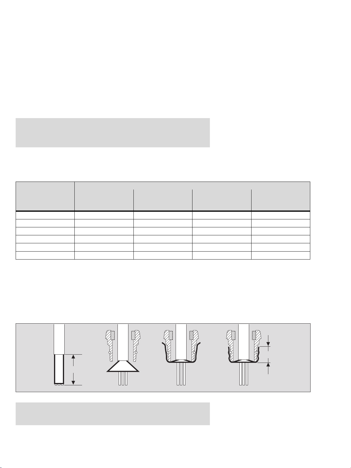
Instalación del Transmisor
Montaje del Transmisor
●
Realizar una fijación con tornillos (diámetro 4 mm) a través de la carcasa
(disposición de taladros, ver la página 29)
Instalación de las conexiones eléctricas
— La colocación y la conexión de la instalación eléctrica sólo debe ser llevada
a cabo por un técnico capacitado y observando las prescripciones pertinentes
sobre los útiles y dispositivos eléctricos en zonas con peligro de explosión,
así como las condiciones de homologación.
Conexión entre el Transmisor y la central
●
Las longitudes máximas posibles de los cables con una resistencia de carga de
250 ohmios se pueden observar en la tabla siguiente.
Tensión mínima
de alimentación
0,5 mm
(36 ohmios/km)
2
(24 ohmios/km)
en la central
18 V 416 m 625 m 833 m 1249 m
20 V 555 m 833 m 1110 m 1666 m
22 V 694 m 1041 m 1388 m 2082 m
24 V 833 m 1249 m 1666 m 2498 m
26 V 972 m 1457 m 1943 m 2915 m
28 V 1110 m 1666 m 2221 m 3331 m
Sección de conductor
0,75 mm
2
1,0 mm
2
(18 ohmios/km)
1,5 mm
2
(12 ohmios/km)
●
Con cable apantallado de 3 conductores, de blindaje trenzado con un grado de
cobertura de ≥ 80 %, diámetro exterior mínimo 7, máximo 12 mm. Conectar lo más
corto posible el blindaje a la masa de la central.
●
Colocar el blindaje de cable como se muestra en la figura en torno al cono de
plástico y alojarlo en el racor de cable metálico. Apretando el racor de cable, el
blindaje del cable adquiere contacto eléctrico con el recubrimiento conductible
interior de la carcasa del Transmisor. Mediante esta medida se garantiza la
resistencia a perturbaciones e interferencias exigida por la norma EN 50 270.
aprox. 55 mm
Nota:
El prensa del cable está exclusivamente permitido para una instalación
estacionaria. Ésté es apropiado para un diámetro de cable de 7 a 12 mm.
aprox. 12 mm
00223810_1_es.eps
Página 8 de 42 páginas
9023810 - 2a edición - Septiembre 2005
Page 93

●
Desmontar la tapa de la carcasa del Transmisor
●
Conexión el transmisor a la Unidad de Control conforme a lo indicado en la figura.
Tipo XTR 0090 resp. XTR 0091:
●
Conexión de la cabeza medidora SE Ex al Transmisor conforme a lo indicado en
la figura.
— El aparato central y la unidad de alimentación de red pueden estar también
alojados juntos en un mismo aparato.
Instalación del Transmisor
Unidad de
+24 voltios
0 voltios
alimentación
de red
24 V ±20 %,
0,15 A
PEX 3000
Tipo XTR 0000,
XTR 0001,
XTR 0010
y XTR 0011
Pantalla conectada
al prensa
de entrada
Pantalla conectada
al prensa
de entrada
➀➁➂
PEX 3000
Tipo XTR 0090,
XTR 0091
Cabeza medidora
Polytron SE Ex
Longitud máx. de cable
50 m
100 m
150 m
4 a 20 mA
0 mA
Unidad
control
Sección de conductor
2
0,5 mm
2
1,0 mm
2
1,5 mm
PEX 3000, todos los tipos PEX 3000, tipos XTR 0090 y XTR 0091
Conexión con la Unidad de control: Conexión con la cabeza medidora
Conectar borna +24V con +24 voltios Conectar borna marron con borna 1
Conectar borna SIG con entrada de 4 a 20 mA Conectar borna amarillo con borna 2
Conectar borna 0 V con 0 voltios Conectar borna negro con borna 3
9023810 - 2a edición - Septiembre 2005
Página 9 de 42 páginas
00323810_1_es.eps
Page 94

Instalación del Transmisor
Disposición de los cables en el interior del Transmisor
●
Insertar en la borna elástica los conductores individuales aislados (longitud de
conductor mín. 55 mm) lo más directo posible con el extremo desnudo en
aprox. 5 mm.
— Para el cableado de la alimentación y de la transmisión de señales sólo se
deberán emplear cables con una sección de 0,75 mm
cables con una sección de 0,5 mm
2
se pueden emplear, cuando éstos
2
como mínimo. Los
dispongan de una ferrita aislada (tipo Zoller+Fröhlich, tipo V3AE0005,
V3AE0037 o equivalente). De este modo se garantiza que se respete el modo
de protección IP 30, aún estando abierta la tapa de la carcasa para fines de
mantenimiento.
Sólo para los tipos XTR 0090 y XTR 0091:
— Para el cableado entre el Transmisor de medición de gas y la cabeza medidora
de gas (p.ej. Sensing Head SE Ex PR M) sólo se deben emplear cables con una
sección de 0,75 mm
2
como mínimo. Cables con una sección de 0,5 mm2 se
pueden emplear, cuando éstos disponen de una ferrita aislada (Zoller+Fröhlich,
tipo V3AE0005, V3AE0037 o equivalente). De este modo se garantiza que se
respete el modo de protección IP 30 aún estando abierta la tapa de la carcasa
para fines de mantenimiento.
OK
2
3
M
00423810_1.eps
Nota: Los cables desnudos no deben sobresalir de las bornas elásticas.
El concepto de protección contra explosiones ha sido concebido, de
manera que durante los trabajos de mantenimiento no sea posible entrar
en contacto con cables desnudos con una sonda con un diámetro de
2,5 mm (modo de protección IP 30).
Manejo de las bornas elásticas en el Transmisor
1 2 3 1 2 3
1
Introducir en la borna un destornillador (punta de 3 mm) o la herramienta especial
indicada (ver también la lista para pedidos, página 27).
Presionar el muelle hacia abajo. De este modo se abre el borne en la parte
inferior. Meter el extremo desnudo del cable en la parte inferior, en caso
necesario con la ferrita de cable.
Retirar el destornillador o la herramienta especial, respectivamente, de la parte
superior. La conexión eléctrica queda establecida por la fuerza de muelle.
Atención: Las bornas elásticas están unidos fijamente con el convertidor
de 4 a 20 mA. En caso de daños en las bornas a causa de una
manipulación inadecuada, se deberá cambiar el convertidor completo.
00523810_1.eps
Página 10 de 42 páginas
9023810 - 2a edición - Septiembre 2005
Page 95

Estructura de menús
El Transmisor PEX 3000 está equipado con un display de 7 segmentos de dos
cifras y dos teclas de scrolling o desplazamiento (tecla q y tecla l), con cuya ayuda
se puede navegar por los menús escritos.
El accionamiento simultáneo de las dos teclas de scrolling tiene la función de una
tecla OK y se simboliza por medio de las "Teclas (q+l)".
La tecla l está caracterizada por una M adicional para así señalar que accionando
esta tecla se pasa del servicio de medición al menú de calibración o al menú de
mantenimiento.
Ambos menús sólo pueden ser abandonados por medio de la tecla q.
El display y los pulsadores son accesibles después de abrir la carcasa del
Transmisor (ver la figura).
Atención:
Al abrir la carcasa del Transmisor se pierde la protección contra la explosión
de polvo. ¡En caso dado, se tiene que anular temporalmente la zona Ex!
Estructura de menús
OK
Indicaciones sobre el display
Durante el servicio de medición, en el display de dos cifras se indica la
concentración actualmente medida, a saber, en % LIE (00 a 99 resp. 0,0
a 9,9 % LIE).
Calibración y mantenimiento
Si el Transmisor se encuentra en el menú de calibración o de mantenimiento, este
estado es indicado por un punto parpadeante a aprox. 1 Hz (en la parte inferior
derecha).
Fallos
Los estados de Fallo o defecto se indican por medio de una indicación alternante de
dos rayas horizontales y el código de error actual (E0 a E8).
Comportamiento después de la conexión
Directamente después de la conexión se activan durante unos 5 segundos todos los
14 segmentos LED, incluyendo los dos puntos, para así poder detectar un eventual
error en el display ("Test de lámparas").
Seguidamente cambia la indicación en el display durante un minuto
aproximadamente entre dos rayas horizontales y el valor medido actual para
conmutar a continuación al servicio de medición. Durante este tiempo no es posible
el acceso a los menús de calibración y de mantenimiento.
00623810_1.eps
9023810 - 2a edición - Septiembre 2005
Página 11 de 42 páginas
Page 96

Estructura de menús
Modo de medición
Indicación del valor medido de 0 a 99 resp. 0 a 9,9
Salida de corriente de 4 a 20 mA
q
SL
Test 4-20 mA
Fallo
eliminado
Mayor
(>3 s)
q
ZE
Calibración
punto cero
q
SP
Calibración
sensibilidad
Tecla
lM
corto (>1 s y <3 s)
l
Teclas
q+l
Teclas
q+l
Salida de corriente
3.4 mA
Salida de corriente
3.4 mA
Aparición
de un fallo
Fallo
Indicación E0 a E8
Salida de corriente 1 mA
Ajuste del
punto cero
ver página 13
Ajuste de la
sensibilidad
ver página 13
Menú de calibración
Teclas
q+l
l
Salida de corriente
4.0 mA
Poner a X mA la
salida de corriente
ver página 14
q
Calibración 4-20 mA
Ajuste punto decimal
Versión de software
CL
l
q
CU
Ajuste corriente
de sensor
q
q
l
dP
l
So
Teclas
q+l
Teclas
q+l
Teclas
q+l
Teclas
q+l
Salida de corriente
4.0 mA
Salida de corriente
3.4 mA
Salida de corriente
3.4 mA
Salida de corriente
3.4 mA
Calibración salida
de corriente
ver página 14
Ajuste de la corriente
de sensor
ver página 15
Indicación del
punto decimal
ver página 15
Indicación de la
versión de software
ver página 15
Menú de mantenimiento
Si no se pulsa ninguna tecla durante 4 minutos en cualquiera de los estados, se abandona automáticamente el menú
sin realizar un almacenamiento y se indica de nuevo el valor medido actual.
02223810_1_es.eps
Página 12 de 42 páginas
9023810 - 2a edición - Septiembre 2005
Page 97

Menú de calibración
● Para acceder al menú de calibración, pulsar la tecla l durante más de un
segundo y menos de tres segundos. En el display parpadea el punto de la parte
inferior derecha, para indicar el estado de calibración.
ZE – Ajuste del punto cero
● Con la tecla q o l navegar hasta que en el display se visualice ZE ("ZEro") y
confirmar pulsando las teclas (q+l). La señal de salida conmuta a 3,4 mA.
— En el display se indica la concentración de gas actualmente medida (los valores
negativos se indican hasta "–9").
● Alimentar el sensor con gas cero y esperar hasta que se estabilice la indicación
(3 minutos como máximo).
● Pulsar las teclas (q+l), para almacenar el valor indicado como nuevo punto
cero.
● Pulsar de nuevo las teclas (q+l) para terminar la función. Ahora se visualiza otra
vez la indicación ZE.
● Pulsar la tecla l para ajustar a continuación la sensibilidad
o
● Pulsar la tecla q para conmutar de nuevo al modo de medición.
Menú de calibración
00723810_1.eps00823810_1.eps
SP – Ajuste de la sensibilidad
● Con ayuda de la tecla q o l navegar hasta que en el display se visualice SP
("SPan") y confirmar pulsando las teclas (q+l).
— En el display se indica en % LIE la concentración del gas de prueba empleada en
la última calibración.
— Con ayuda de la tecla q o l se puede ajustar la concentración del gas de prueba
actualmente empleado en pasos de 1 % LIE entre 20 y 99 % LIE (resp. en pasos
de 0,1-% LIE entre 2,0 y 9,9 % LIE). Accionando las teclas durante más tiempo se
activa la función de repetición.
● Pulsar las teclas (q+l), alimente el sensor con gas de prueba y esperar hasta
que se haya estabilizado el valor medido indicado (3 minutos como máximo).
● Pulsar las teclas (q+l), para calcular de nuevo y almacenar la amplificación
interna.
● Pulsar las teclas (q+l), ahora se indica un valor de referencia para la
sensibilidad del sensor (señal de puente de amplificación constante).
● Pulsar las teclas (q+l) para terminar la función. Ahora se visualiza de nuevo la
indicación SP.
● Pulsando dos veces la tecla q se retorna al servicio de medición.
9023810 - 2a edición - Septiembre 2005
Página 13 de 42 páginas
Page 98

Menú de mantenimiento
Menú de mantenimiento
● Para acceder al menú de mantenimiento, pulsar la tecla l durante más de
3 segundos hasta que en el display se visualice "SL" y parpadee el punto de la
parte inferior derecha, para así indicar el estado de mantenimiento.
SL – Poner la salida de corriente a X mA
Con ayuda de esta función se puede ajustar la señal de salida del Transmisor a
valores constantes determinados para fines de prueba.
Atención:
¡Esta función puede activar señales de alarma en el aparato central!
● Con las teclas q o l navegar hasta que en el display se visualice SL ("Set Loop")
y confirmar la indicación pulsando las teclas (
— La salida de corriente se pone a 4 mA, y en el display se indica "04".
● Con la tecla q o l se puede ajustar la salida de corriente en pasos de 1 mA
a valores entre 1 y 22 mA. Pulsando las teclas durante más tiempos se activa la
función de repetición.
● Pulsar las teclas (q+l), para terminar la función. Ahora se visualiza de nuevo la
indicación SL.
● Pulsando una sola vez la tecla q se retorna al servicio de medición.
q+l).
00923810_1.eps01023810_1.eps
CL – Calibración de la salida de corriente
Con ayuda de esta función se puede calibrar la salida de corriente del Transmisor,
es decir, a la indicación de 0 % LIE se le asigna una corriente de 4 mA, y a la
indicación de 100 % LIE o de 10 % LIE, respectivamente, una corriente de 20 mA.
Por lo general, la señal de salida en la central puede ser medida como caída de
tensión a través de la resistencia de entrada, de lo contrario se tiene que interrumpir
el bucle de 4 a 20 mA e insertarse en bucle un amperímetro.
Atención:
¡Si se interrumpe el bucle en el Transmisor para fines de medición, se anula la
protección ante explosiones!
● Navegar con la tecla q o l hasta que en el display se visualice CL ("Calibrate
Loop").
● Pulsar las teclas (q+l). De este modo se ajusta el punto inferior de referencia,
y en el display se indica "04" correspondiente a 4 mA.
● Leer la corriente en el amperímetro o en la central, respectivamente.
● Con ayuda de la tecla q o l, ajustar la salida de corriente, de manera que en el
amperímetro se indique una corriente lo más exacta posible de 4 mA (3,95 a
4,05 mA). Accionando durante más tiempo las teclas se activa la función de
repetición.
● Pulsar las teclas (q+l). De este modo se almacena el punto de referencia
inferior y se conmuta al punto de referencia superior, en el display se indica "20"
correspondiendo a 20 mA.
● Leer la corriente en el amperímetro o en la central, respectivamente.
● Con la tecla q o l ajustar la salida de corriente, de manera que en el
amperímetro se indique una corriente lo más exacta posible de 20 mA (19,95 a
20,05 mA). Accionando durante más tiempo las teclas se activa la función de
repetición.
● Pulsar las teclas (q+l). De este modo se almacena el punto de referencia
superior y se termina la función. Ahora se visualiza de nuevo la indicación CL.
● Accionando dos veces la tecla q se vuelve al servicio de medición.
Página 14 de 42 páginas
9023810 - 2a edición - Septiembre 2005
Page 99

CU – Ajuste de la corriente del sensor
La finalidad de esta función es el ajuste de la corriente de sensor, siempre que un
sensor vaya a ser operado con una corriente de sensor diferente a la ajustada en
fábrica.
En fábrica se ajustaron:
Tipo XTR 0000, XTR 0001, XTR 0090 y XTR 0091: 270 mA
Tipo XTR 0010 y XTR 0011: 276 mA
Atención: ¡Después del ajuste de la corriente de sensor, el Transmisor tiene
que ser calibrado de nuevo en cuanto al punto cero y a la sensibilidad!
● Con la tecla q o l navegar hasta que en el display se visualice CU ("CUrrent")
y confirmar pulsando las teclas (
q+l).
— En el display se indican las dos últimas cifras de la corriente de sensor actual, por
ejemplo la indicación para 270 mA es "70".
● Con la tecla q o l se puede ajustar la corriente de sensor, en pasos de 1 mA,
entre 240 mA (indicación "40") y 300 mA (indicación "00"). Pulsando las teclas
durante más tiempo se activa la función de repetición.
● Pulsar las teclas (q+l), para activar el valor indicado como nuevo ajuste de la
corriente de sensor, almacenarlo y terminar la función. Ahora se indica de nuevo
CU.
● Accionando tres veces la tecla q se retorna al servicio de medición.
Menú de mantenimiento
01123810_1.eps01223810_1.eps01323810_1.eps
dP – Activación del punto decimal
Con esta función se puede activar el punto decimal en el display, cuando el
Ex-Sensor LC M (tipo XTR 0010 ó XTR 0011) o el Transmisor remoto tipo XTR 0090
ó XTR 0091 con la cabeza medidora SE Ex LC M se utiliza con un margen de
medición de 0 a 9,9 % LIE.
El punto decimal se visualiza sólo en las indicaciones de concentración en % LIE.
● Con la tecla q o l navegar hasta que en el display se visualice dP ("decimal
Point") y confirmar pulsando las teclas (q+l). Si el punto decimal ya había sido
activado, éste se indica ahora aquí y el punto parpadeante de la parte inferior
derecha se desactiva.
● Activar o desactivar el punto decimal con la tecla q o l.
● Pulsar las teclas (q+l) para almacenar el estado actual y terminar la función.
En el display se visualiza dP. El punto decimal conectado ya no puede verse, en
su lugar parpadea de nuevo el punto en la parte inferior derecha.
● Accionando cuatro veces la tecla q se retorna al servicio de medición.
So – Indicación de la versión del software
Con el fin de documentar las modificaciones de software eventualmente necesarias,
con esta función se puede indicar la versión de software implementada en el
Transmisor.
● Pulsando la tecla q o l, navegar hasta que en el display se visualice So
("Software") y confirmar pulsando las teclas (q+l).
— En el display se visualiza un número entre "0.1" y "9.9", con el que se caracteriza
la versión del software del Transmisor.
● Pulsar las teclas (q+l) para terminar la función. Ahora se visualiza de nuevo la
indicación So.
● Accionar cinco veces la tecla q para volver al servicio de medición.
9023810 - 2a edición - Septiembre 2005
Página 15 de 42 páginas
Page 100

Puesta en servicio del Transmisor
Puesta en servicio del Transmisor
● Abrir la tapa de la carcasa del Transmisor.
Atención:
Después de abrir la carcasa del Transmisor ya no se dispone de una
protección contra la explosión de polvo. ¡La zona Ex tiene que ser
declasificada en caso necesario!
Conexión de la tensión de alimentación
— Directamente después de la conexión se activan durante aprox. 5 segundos
todos los 14 segmentos LED, incluyendo los dos puntos ("Test de lámparas"),
para así en caso dado poder detectar errores en el display. Durante este tiempo
se procesan en el Transmisor rutinas de comprobación internas, la señal de
salida del Transmisor es de 1 mA.
— Seguidamente, la indicación cambia con aprox. 1 Hz entre dos rayas horizontales
y el valor medido actual, durante este tiempo la señal de salida del Transmisor es
de 3,4 mA.
— El Transmisor está listo para el servicio después de un minuto.
Cuando el punto cero no sobrepasa en más de 5 % el valor mínimo del margen
de medición, éste indica el valor medido actual, la señal de salida corresponde al
valor medido.
Tipo XTR 0090 ó XTR 0091 en combinación con la cabeza medidora
SE Ex LC M:
● Ajustar a 276 mA la corriente del sensor con la función "CU – Ajuste de la
corriente del sensor" (ver la página 15).
● Antes de proceder a la calibración, esperar un período de adaptación del
Transmisor de 10 minutos como mínimo (tiempo de adaptación del sensor).
Página 16 de 42 páginas
9023810 - 2a edición - Septiembre 2005
 Loading...