

Page 1
Dräger Pac 6x00 / 8x00
Technical manual
Page 2

Page 3

3
Contents
en
Contents
1 Safety-related information . . . . . . . . . . . . . . . . . . .4
1.1 Basic safety information . . . . . . . . . . . . . . . . . . . . . .4
1.2 Safety information on explosion protection . . . . . . . .4
2 Conventions used in this document . . . . . . . . . . .4
2.1 Definition of alert icons . . . . . . . . . . . . . . . . . . . . . . .4
2.2 Typographical conventions . . . . . . . . . . . . . . . . . . . .4
2.3 Glossary . . . . . . . . . . . . . . . . . . . . . . . . . . . . . . . . . .4
3 Description . . . . . . . . . . . . . . . . . . . . . . . . . . . . . . .5
3.1 Product overview . . . . . . . . . . . . . . . . . . . . . . . . . . .5
3.1.1 Gas detector . . . . . . . . . . . . . . . . . . . . . . . . . . . . . . .5
3.1.2 Display . . . . . . . . . . . . . . . . . . . . . . . . . . . . . . . . . . .5
3.2 Intended use . . . . . . . . . . . . . . . . . . . . . . . . . . . . . . .5
3.3 Approvals . . . . . . . . . . . . . . . . . . . . . . . . . . . . . . . . .5
4 Use . . . . . . . . . . . . . . . . . . . . . . . . . . . . . . . . . . . . . .6
4.1 Preparations for use . . . . . . . . . . . . . . . . . . . . . . . . .6
4.1.1 Initial start-up . . . . . . . . . . . . . . . . . . . . . . . . . . . . . .6
4.1.2 Switching on the gas detector . . . . . . . . . . . . . . . . . .6
4.1.3 Switching off the gas detector . . . . . . . . . . . . . . . . . .6
4.2 Before entering the workplace . . . . . . . . . . . . . . . . .6
4.2.1 Activating the quick menu . . . . . . . . . . . . . . . . . . . . .6
4.2.2 Opening the quick menu . . . . . . . . . . . . . . . . . . . . . .6
4.2.3 Carrying out a manual bump test . . . . . . . . . . . . . . .6
4.2.4 Information display . . . . . . . . . . . . . . . . . . . . . . . . . .7
4.2.5 Error and warning code displays . . . . . . . . . . . . . . . .7
4.3 During operation . . . . . . . . . . . . . . . . . . . . . . . . . . . .7
5 Calibrating the gas detector . . . . . . . . . . . . . . . . .8
5.1 Opening the maintenance menu . . . . . . . . . . . . . . . .8
5.2 Carrying out a manual fresh air calibration . . . . . . . .8
5.3 Carrying out a manual span calibration . . . . . . . . . .9
5.4 Carrying out manual calibration with the Dräger CC-Vi-
sion Basic . . . . . . . . . . . . . . . . . . . . . . . . . . . . . . . . .9
5.5 Carrying out an automatic calibration with the Dräger
X-dock . . . . . . . . . . . . . . . . . . . . . . . . . . . . . . . . . . . .9
6 Troubleshooting . . . . . . . . . . . . . . . . . . . . . . . . . .10
7 Maintenance . . . . . . . . . . . . . . . . . . . . . . . . . . . . .13
7.1 Configuring the gas detector . . . . . . . . . . . . . . . . . .13
7.2 Operating time alarm / end of the operating time . .13
7.3 Data logger . . . . . . . . . . . . . . . . . . . . . . . . . . . . . . .13
7.4 Replacing the sensor . . . . . . . . . . . . . . . . . . . . . . .13
7.5 Replacing the battery . . . . . . . . . . . . . . . . . . . . . . .14
7.6 Replacing the dust and water filter . . . . . . . . . . . . .15
8 Device settings . . . . . . . . . . . . . . . . . . . . . . . . . . .15
8.1 Factory setting . . . . . . . . . . . . . . . . . . . . . . . . . . . .15
8.2 Alarm settings . . . . . . . . . . . . . . . . . . . . . . . . . . . . .16
9 Disposal . . . . . . . . . . . . . . . . . . . . . . . . . . . . . . . . .17
10 Technical data . . . . . . . . . . . . . . . . . . . . . . . . . . . .17
10.1 Gas detector . . . . . . . . . . . . . . . . . . . . . . . . . . . . . .17
10.2 Technical data of the sensors and the measuring de-
vice settings for Pac 6000/6500 . . . . . . . . . . . . . . .18
10.3 Technical data of the sensors and the measuring de-
vice settings for Pac 8000 . . . . . . . . . . . . . . . . . . . .19
10.3.1 Sensors for Pac 8500 DUAL . . . . . . . . . . . . . . . . . .21
10.3.2 Cross-sensitivities . . . . . . . . . . . . . . . . . . . . . . . . . .22
Page 4
4
Safety-related informationen
1 Safety-related information
1.1 Basic safety information
Before using this product, carefully read the associated
instructions for use. This document does not replace the
instructions for use.
Incorrect calibration
An incorrect calibration leads to incorrect measured values.
► The sensitivity must be checked daily before first using the
device, with a known concentration of the gas to be
measured that corresponds to 25 to 50 % of the final
concentration. The accuracy must amount to 0 to +20 % of
the actual value. The accuracy can be corrected by
calibration.
1.2 Safety information on explosion
protection
Devices or components that are used in potentially explosive
atmospheres and which are tested and approved in
accordance with national, European or international explosion
protection guidelines may only be used under the approved
conditions in compliance with the statutory provisions.
Oxygen-enriched atmospheres
Explosion protection is not guaranteed in oxygen-enriched
atmospheres (>21 Vol% O
2
).
► Remove the device from the potentially explosive
atmosphere.
Risk of explosion!
► Do not open the gas detector in explosion-hazard areas.
Specific application conditions
In certain extreme conditions, open plastic parts and non-
earthed metal parts of the housing may store a combustible
level of electrostatic charge.
Activities such as carrying the device in a bag or attached
to a belt, operating the button field or cleaning the device
with a damp cloth do not represent a significant
electrostatic danger. However, if a mechanism which
generates static charge, such as repeated rubbing against
clothing, is identified, suitable precautionary measures
must be implemented, e.g. the use of anti-static clothing
and anti-static footwear.
2 Conventions used in this
document
2.1 Definition of alert icons
The following alert messages are used in this document to
provide and highlight areas of the associated text that require
a greater awareness by the user. A definition of the meaning of
each alert message is as follows:
WARNING
Indicates a potentially hazardous situation. If not avoided, it
could result in death or serious injury.
NOTICE
Indicates a potentially hazardous situation. If not avoided, it
could result in damage to the product or environment.
2.2 Typographical conventions
This symbol identifies information that make the product
easier to use.
2.3 Glossary
Technical term Explanation
Operation signal A periodic optical (green LED) and/or
acoustic signal.
D-Light The D-Light allows the user to check and
indicate compliance with certain settings
(e.g. bump test interval). The green LED
flashes for a short period and
superimposes the optical operation
signal.
Page 5
Description
5
en
3 Description
3.1 Product overview
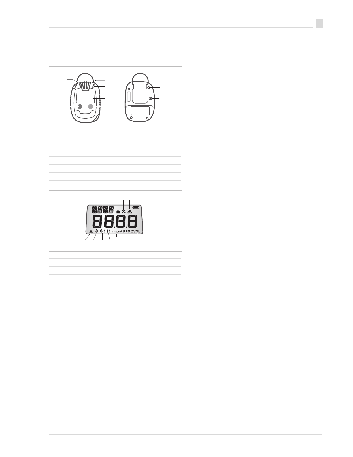
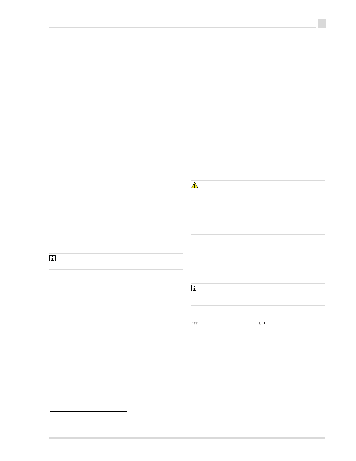
3.1.1 Gas detector
3.1.2 Display
3.2 Intended use
The Dräger Pac 6x00/8x00 is a gas detector and is used to
measure and alert the user of gas concentrations in the
ambient air.
3.3 Approvals
A copy of the name plate and the declaration of conformity are
provided in the enclosed supplementary documentation (order
no. 90 33 741).
The name plate on the gas detector must not be concealed.
1 Alarm LEDs 6 [OK] button
2 Operation signal/
D-Light
7[▼] button
3 Gas inlet 8 Screw (4x)
4 Horn 9 IR interface
5Display
1 Key word symbol 6 Span calibration
2 Error symbol 7 Fresh air adjustment
3 Information symbol 8 TWA/STEL
4 Battery charge status 9 Peak concentration
5 Measurement unit
8 (4x)
1
1
2
4
3
5
6
7
9
00333742.eps
152 3 4
6798
00733742.eps
Page 6
6
Useen
4Use
4.1 Preparations for use
4.1.1 Initial start-up
The gas detector remains in deep sleep mode upon delivery
and must be activated during the initial start-up.
1. Hold down the [▼] button for approx. 3 s.
This activates the gas detector.
4.1.2 Switching on the gas detector
1. Hold down the [OK] button for approx. 3 s.
The following is displayed or activated:
Display elements, LEDs, alarm signal and vibration alarm
Self-test
Software version and gas name
Alarm thresholds A1 and A2
Time to next calibration (configurable)
Time to expiration of the bump test interval (configurable)
Before every use, check whether the display elements and
information are displayed correctly.
A warm-up phase takes place when first switching on the gas
detector (duration depends on the sensor type; see the sensor
data sheet).
4.1.3 Switching off the gas detector
Hold down both keys for approx. 3 s, until shut-down is
complete.
4.2 Before entering the workplace
WARNING
Serious damage to health!
An incorrect calibration can lead to incorrect measurement
results, which may result in serious damage to health.
► Before performing safety measurements, check the
calibration by way of a bump test, adjust as necessary,
and check all alarm elements. If national regulations exist,
the bump test must be performed in accordance with
these regulations.
WARNING
Incorrect measurement results!
The gas inlet opening is fitted with a filter that protects against
dust and water. Contamination may change the qualities of the
dust and water filter.
► Do not damage the filter. Immediately replace damaged or
blocked filters.
To ensure correct function:
Do no cover the gas inlet opening.
Place the gas detector on clothing near the mouth.
At temperatures below -20 °C, there may be deviations of
>10 % of the measured value if the corresponding sensor
was calibrated at room temperature. Dräger recommends
calibration at the primary application temperature if
measurements will be taken at very low temperatures. This
enables the highest possible measurement accuracy.
After the gas detector has been switched on, the current
measured value is shown in the display.
Check whether the warning [!] appears. If it is displayed, we
recommend performing a bump test, see Section 4.2.3 on
Page 6.
4.2.1 Activating the quick menu
The quick menu can be activated using the Dräger CC-Vision
Basic PC software.
Up to two preferred functions can be saved in the quick menu.
The following functions are available:
Fresh air adjustment
Bump test
4.2.2 Opening the quick menu
Prerequisite:
The quick menu is activated.
To open the quick menu:
1. Press the [▼] button three times within three seconds. A
double signal tone sounds.
2. Depending on the configuration, the fresh air calibration
symbol or the bump test signal will flash.
3. Press the [OK] button to start the feature or press the [▼]
button to switch to the next feature or to return to
measuring mode (depending on the configuration).
The quick menu closes automatically after 60 s of inactivity.
4.2.3 Carrying out a manual bump test
WARNING
Danger to health! Do not inhale the test gas.
► Pay attention to the hazard information in the respective
safety data sheets.
Two modes can be selected for a bump test. Use the Dräger
CC-Vision Basic PC software to set the mode.
Quick bump test (test for alarm triggering)
Checks whether the pre-alarm threshold (A1) is
exceeded (or not reached in the case of O
2
).
Checks whether the concentration remains above the
alarm for a specified period of time.
Checks whether the test duration remains below a
specified maximum time period.
Advanced bump test (test for accuracy)
Checks whether the defined test gas concentration is
reached within a specified tolerance. The tolerance is
defined with a default value for each gas in the gas
detector, but can be adjusted by the user as needed.
Checks whether the test gas concentration remains
within the tolerance window for a specified time period.
Checks whether the test duration remains below a
specified maximum time period.
The bump test can be performed as follows:
Manual bump test (with quick menu)
Bump test with X-dock (see instructions for use for the
Dräger X-dock)
Bump test with the Dräger Bump Test Station (see the quick
reference guide on the Dräger Bump Test Station)
Page 7
Use
7
en
Prerequisites for the manual bump test:
The gas detector is switched on.
A suitable test gas cylinder is available, e.g. a test gas
cylinder (order no. 68 11 130) with the following mixed gas
ratios: 50 ppm CO, 15 ppm H
2
S, 2.5 Vol% CH4, 18 Vol%
O
2
To perform a manual bump test:
1. Prepare a Dräger test gas cylinder. The volume flow must
be 0.5 L/min and the gas concentration must be higher
than the alarm threshold concentration that is to be tested.
2. Connect the gas detector and the test gas cylinder to the
calibration adapter.
3. Press the [▼] button three times within three seconds to
open bump test mode (if configured). A signal tone sounds.
The notice symbol starts flashing.
4. Press the [OK] button to start the bump test.
5. Open the test gas cylinder valve to let test gas flow over the
sensor.
6. If the gas concentration exceeds the alarm threshold A1 or
A2, the corresponding alarm triggers.
Bump test failed: The gas detector switches to error mode
and displays an error. The error symbol flashes, and an
error code is displayed until the error is confirmed.
Subsequently, instead of the measured value, the - – –
display and the error symbol appear. In this case, repeat
the bump test or calibrate the gas detector.
Bump test passed: OK is displayed until the concentration
is below A1.
The result of the bump test (passed or failed) is saved in the
data logger (see Section 7.1 on Page 13).
4.2.4 Information display
Different information can be displayed when the device is on
and off.
The information display closes automatically after 3 s of
inactivity.
When the gas detector is off:
The following information is displayed:
Gas name, full scale deflection and measurement module.
Duration of use (Pac 6000 always, Pac 6500 and 8x00
depending on the configuration)
Device ID
To display the information:
1. Hold down the [▼] button for approx. 1 s while the device
is off.
The gas name, full scale deflection and measurement
module are displayed.
2. Press the [▼] button to display the information
consecutively. The information display closes after the
device ID.
When the gas detector is on:
The following information can be displayed depending on the
configuration:
Error codes
Peak concentration
Time-weighted average (TWA
1)
, not for Pac 6000)
Short-term exposure limit (STEL
1)
, not for Pac 6000)
Duration of use (Pac 6000 always, Pac 6500 and 8x00
depending on the configuration)
Device ID
To display the information:
1. Press the [OK] button in measuring mode.
This displays the peak concentration and the symbol for
peak concentration.
2. Press the [OK] button to display the information
consecutively. The information display closes after the
device ID.
4.2.5 Error and warning code displays
If a warning, an error or a notice is pending, the error or notice
symbol flashes and a three-digit error code appears.
To display the error and warning codes:
1. Press the [OK] button.
If there are several pending error or warning codes, the next
error or warning code can be displayed by pressing the [OK]
button.
4.3 During operation
WARNING
Danger to life and/or risk of explosion!
The following alarms indicate a danger to life and/or explosion
hazard:
A2 alarm
STEL or TWA alarm
Device error
► Immediately leave the hazard area.
The continuous operation of the gas detector is indicated by an
optical and/or acoustic operation signal that is emitted in a 60second cycle (configurable using the Dräger CC-Vision Basic
PC software).
The respective measured value is displayed as an alternating
display for dual sensors.
The operation signal must be turned on for measurements
in accordance with EN 45544 (CO, H2S) or in accordance
with EN 50104 (O2).
If the allowable measuring range is exceeded or a negative
zero drift occurs, the following message appears in the display:
(concentration too high) or (negative drift).
The measuring channels do not need to be checked after a
brief exceeding of the measuring range by the EC measuring
channels (up to one hour) (this does not apply when using
DrägerSensor XXS CO H2-CP).
In the event of an alarm, the corresponding displays, including
the visual, audible and vibration alarms, are activated, see
Section 8.2 on Page 16.
Press the [▼] button to illuminate the display.
1) configurable
Page 8
8
Calibrating the gas detectoren
5 Calibrating the gas detector
WARNING
Danger to health!
Do not inhale the test gas. Observe the hazard warnings on
the corresponding Safety Data Sheets and the instructions for
use of the gas detector! Observe national regulations when
defining calibration intervals.
For Pac 8500, two measuring channels are used for the
calibration.
Calibration must be performed by qualified personnel after
a failed bump test or after a defined calibration interval (see
EU standard EN 50073).
Recommended calibration interval for the O
2
, H2S and CO
sensors: 6 months. Calibration intervals for other gases:
see the instructions for use of the respective
DrägerSensors.
Calibration can be carried out as follows:
Manual calibration or calibration using the Dräger
CC-Vision Basic
Automatic calibration with the Dräger X-dock (see the
instructions for use for the Dräger X-dock)
Automatic calibration with the Dräger Bump Test Station
(see the quick reference guide on the Dräger Bump Test
Station)
5.1 Opening the maintenance menu
The gas detector automatically returns to measuring mode
if no button is pressed in the menu for 1 minute (with the
exception of the span calibration menus, where the menu
remains active for 10 minutes without any activity).
The maintenance menu is password protected.
Factory setting: 001
1. Hold down the [▼] button for 5 seconds.
2. Enter the password. Press the [▼] button to change the
value of the flashing position. Press the [OK] button to
confirm the value. Repeat this procedure to define the next
two values. After the last confirmation with the [OK] button,
the entire password flashes.
3. Press the [OK] button to confirm the password or the [▼]
button to cancel the password.
4. If the correct password is entered, a signal tone sounds
and the fresh air calibration symbol flashes (configurable).
5. Press the [OK] button to open the fresh air calibration or the
[▼] button to switch to the span calibration.
6. Press the [OK] button to open the span calibration or the
[▼] button to switch back to measuring mode.
5.2 Carrying out a manual fresh air
calibration
To improve accuracy, a fresh air calibration can be carried out
if there is a zero deviation.
Observe the following notices for the calibration:
During fresh air calibrations, the zero point of all sensors
(except the DrägerSensors XXS O2) is set to 0. For the
XXS O
2
, the reading is set to 20.9 Vol%.
The DrägerSensor XXS O
3
must be calibrated with a
suitable zero gas which is free from carbon dioxide / ozone
(e.g. N
2
).
To carry out the fresh air calibration:
1. Open the maintenance menu, see Section 5.1 on Page 8.
2. Press the [OK] button while the fresh air calibration symbol
is flashing. The measured value flashes.
3. Press the [OK] button to confirm the fresh air calibration or
the [▼] button to cancel the fresh air calibration.
The gas detector returns to measuring mode, or the span
calibration symbol flashes (depending on the
configuration).
Fresh air calibration passed: A short double tone sounds,
and OK / gas name is shown in an alternating display.
Press the [OK] button to return to measuring mode.
Fresh air calibration failed: A long single tone sounds.
– – – is displayed instead of the measured value. The error
symbol and the fresh air calibration symbol are displayed.
In this case, repeat the fresh air calibration or calibrate the
gas detector.
Page 9

Calibrating the gas detector
9
en
5.3 Carrying out a manual span calibration
Prepare the test gas cylinder, connect the test gas cylinder
to the calibration adapter and connect the calibration
adapter to the gas detector.
1. Open the maintenance menu, see Section 5.1 on Page 8.
2. Press the [OK] button while the span calibration symbol is
flashing. The configured test gas concentration is
displayed. The test gas concentration can be used or
adjusted according to the concentration in the test gas
cylinder.
3. Press the [▼] button to change the configured test gas
concentration. The first position flashed. Press the [▼]
button to change the value of the flashing position. Press
the [OK] button to confirm the value. Repeat this procedure
to define the next three values. After the last confirmation
with the [OK] button, the test gas concentration is
complete.
4. Open the test gas cylinder valve to let test gas flow over the
sensor (flow: 0.5 L/min).
5. Wait until the displayed measured value is stable (after at
least 120 seconds).
6. Press the [OK] button to start the span calibration. The
concentration display flashes.
7. As soon as the measured value displays a stable
concentration, press the [OK] button to confirm the span
calibration or the [▼] button to cancel the span calibration.
Span calibration passed: A short double tone sounds, and
OK / gas name is shown in an alternating display. Press
the [OK] button to return to measuring mode.
Span calibration failed: A tone sounds.
––– is displayed instead of the measured value. The error
symbol and the span calibration symbol are displayed. In
this case, repeat the span calibration.
To test the measured value configuration times, allow t90
test gas to flow over the calibration adapter on the gas
detector. Check the results in accordance with the
information in the table (see the supplementary
documentation, order no. 90 33 741) up to a reading of
90 % of the final display.
For Pac 8500, the span calibration is carried out
consecutively for the various gasses.
5.4 Carrying out manual calibration with the
Dräger CC-Vision Basic
To calibrate the gas detector using the Dräger CC-Vision Basic
PC software:
1. Connect the gas detector to a PC using the communication
module.
2. The calibration can be carried out using the Dräger
CC-Vision Basic PC software. For further information, see
the Dräger CC-Vision Basic online help.
A calibration interval can be set using the “Configurable
operating time” (in days) feature, see Section 7.1 on
Page 13.
5.5 Carrying out an automatic calibration
with the Dräger X-dock
The gas detector can be automatically calibrated using the
Dräger X-dock, see the Dräger X-dock instructions for use.
Page 10

10
Troubleshootingen
6 Troubleshooting
An error message is displayed in the event of instrument faults. The number that appears below the message is used for service
functions. If the fault remains after turning the device on and off several times, contact the service of Dräger.
Error code Cause Remedy
101 Life span of the gas detector expired. Use a new Pac gas detector.
102 The user's service life counter has elapsed. Reset the service life counter with the Dräger
CC-Vision Basic PC software.
103 Gas detector faulty. Contact the service of Dräger.
104 Program code checksum error. Contact the service of Dräger.
105 Bump test interval expired. Carry out bump test, see see Section 4.2.3 on
Page 6.
106 Calibration interval expired. Carry out a span calibration.
107 Software error Contact the service of Dräger.
109 General error. For example, menu functions cannot
be carried out.
Check the configuration, view the error code (e.g. on
the information display or with the Dräger CC-Vision
Basic PC software)
111 Alarm element test failed: Alarm lamp. Repeat the alarm element test with X-dock.
112 Alarm element test failed: Alarm horn. Repeat the alarm element test with X-dock.
113 Alarm element test failed: Vibration motor. Repeat the alarm element test with X-dock.
114 Parameter check failed. Correct the parameters and repeat the test with
X-dock.
115 Gas detector deactivated by X-dock. Activate the gas detector with X-dock.
116 Wrong software version. Update the software.
117 User parameters implausible. Check and adjust the configuration of the user
parameters.
131 Gas detector faulty. Contact the service of Dräger.
132 Parameter checksum error. Carry out a sensor inauguration using the Dräger
CC-Vision Basic PC software.
133 Wrong software version for the options board Update the software.
134 Hardware error. Contact the service of Dräger.
201 No valid zero adjustment of DrägerSensor XXS
measuring channel 1.
Carry out a fresh air calibration, see Section 5.2 on
Page 8.
202 No valid span calibration of DrägerSensor XXS
measuring channel 1.
Carry out a span calibration, see Section 5.2 on
Page 8.
203 The measured value of DrägerSensor XXS
measuring channel 1 is in the negative range.
Carry out a fresh air calibration, see Section 5.2 on
Page 8.
204 DrägerSensor XXS measuring channel 1 is faulty or
not connected.
Check DrägerSensor XXS measuring channel 1, see
Section 7.4 on Page 13.
205 Error during the bump test of DrägerSensor XXS
measuring channel 1.
Repeat the bump test and calibrate or replace
DrägerSensor XXS measuring channel 1 if
necessary, see Section 7.4 on Page 13.
206 Faulty filter test. Repeat the filter test with X-dock.
207 Faulty rise time test. Repeat the rise test with X-dock.
208 User parameters of the sensor implausible. Check and adjust the configuration of the sensor
parameters.
212 Calibration interval of DrägerSensor XXS measuring
channel 1 expired.
Carry out a calibration, see Section 5 on Page 8.
225 Compensation channel error on DrägerSensor XXS
measuring channel 1.
Carry out a calibration, see Section 5 on Page 8.
Page 11

Troubleshooting
11
en
227 Sensor hardware on the gas detector faulty. Contact the service of Dräger.
228 Compensation channel calibration error on
DrägerSensor XXS measuring channel 1.
Carry out a calibration, see Section 5 on Page 8.
301 No valid zero adjustment of DrägerSensor XXS
measuring channel 2.
Carry out a fresh air calibration, see Section 5.2 on
Page 8.
302 No valid span calibration of DrägerSensor XXS
measuring channel 2.
Carry out a span calibration, see Section 5.2 on
Page 8.
303 The measured value of DrägerSensor XXS
measuring channel 2 is in the negative range.
Carry out a fresh air calibration, see Section 5.2 on
Page 8.
304 DrägerSensor XXS measuring channel 2 is faulty or
not connected.
Check DrägerSensor XXS measuring channel 2, see
Section 7.4 on Page 13.
305 Error during the bump test of DrägerSensor XXS
measuring channel 2.
Repeat the bump test and calibrate or replace
DrägerSensor XXS measuring channel 2 if
necessary, see Section 7.4 on Page 13.
306 Faulty filter test. Repeat the filter test with X-dock.
307 Faulty rise time test. Repeat the rise test with X-dock.
308 User parameters of the sensor implausible. Check and adjust the configuration of the sensor
parameters.
312 Calibration interval for measuring channel 2 expired. Carry out a calibration, see Section 5 on Page 8.
325 Compensation channel error on DrägerSensor XXS
measuring channel 2.
Carry out a calibration, see Section 5 on Page 8.
327 Gas detector faulty. Contact the service of Dräger.
328 Compensation channel calibration error on
DrägerSensor XXS measuring channel 2.
Carry out a calibration, see Section 5 on Page 8.
Error code Cause Remedy
Warning code Cause Remedy
151 Dräger service life expired. Use a new Pac gas detector.
152 The user's service life counter will elapse soon. Reset the service life counter with the Dräger
CC-Vision Basic PC software.
153 Data memory 90% full. Read the data memory and clear it at the next
opportunity.
154 Data memory full. Read the data memory and clear it.
155 Bump test interval expired. Carry out bump test, see see Section 4.2.3 on
Page 6.
159 General warning pending. Menu functions cannot
be carried out (e.g. notice indicating a warming up
sensor).
View the notice code on the information display and
confirm it if necessary.
160 Date and time incorrect, e.g. after battery change. Set the date and time with the Dräger CC-Vision
Basic PC software.
251 DrägerSensor XXS measuring channel 1 warming
up (warm-up phase 1).
Wait until warm-up time is complete.
252 DrägerSensor XXS measuring channel 1 warming
up (warm-up phase 2).
Wait until warm-up time is complete.
253 Measuring channel 1 concentration has drifted into
the negative range.
Carry out a fresh air calibration for DrägerSensor XXS
measuring channel 1, see Section 5.2 on Page 8.
254 The temperature is too high. Operate the gas detector within the permissible
temperature range.
Page 12

12
Troubleshootingen
255 The temperature is too low. Operate the gas detector within the permissible
temperature range.
256 Calibration interval for DrägerSensor XXS
measuring channel 1 expired.
Carry out a span calibration for DrägerSensor XXS
measuring channel 1, see Section 5.3 on Page 9
275 Compensation channel calibration interval Carry out a calibration for DrägerSensor XXS
measuring channel 1, see Section 5 on Page 8.
276 Calibration necessary because of over-gassing of
the compensation channel.
Carry out a calibration for DrägerSensor XXS
measuring channel 1, see Section 5 on Page 8.
351 DrägerSensor XXS measuring channel 2 warming
up (warm-up phase 1).
Wait until warm-up time is complete.
352 DrägerSensor XXS measuring channel 2 warming
up (warm-up phase 2).
Wait until warm-up time is complete.
353 Measuring channel 2 concentration has drifted into
the negative range.
Carry out a fresh air calibration for DrägerSensor XXS
measuring channel 2, see Section 5.2 on Page 8.
354 The temperature is too high. Operate the gas detector within the permissible
temperature range.
355 The temperature is too low. Operate the gas detector within the permissible
temperature range.
356 Calibration interval for DrägerSensor XXS
measuring channel 2 expired.
Carry out a span calibration for DrägerSensor XXS
measuring channel 2, see Section 5.3 on Page 9
Warning code Cause Remedy
Page 13

Maintenance
13
en
7 Maintenance
The following maintenance instructions must be carefully read,
understood and followed to prevent flammable or combustible
atmospheres from igniting and to ensure that the intrinsic
safety of the gas detector is not impaired.
WARNING
Incorrect measurement!
► A bump test and/or calibration must be performed each
time the gas detector is opened. This includes any battery
change as well as each sensor replacement in the gas
detector.
NOTICE
Damage to components!
The gas detector contains components at risk of charging.
Before opening the gas detector, make sure that the operator
is earthed in order to prevent damage to the gas detector. For
example, earthing may be ensured by an ESD workplace
(electro static discharge).
NOTICE
Damage to the gas detector!
When replacing the battery or the sensor, make sure that no
components are damaged or short-circuited.
► Do not use sharp objects to remove the battery or the
sensor.
WARNING
Replacing components may impair the intrinsic safety of the
gas detector. The following maintenance instructions must be
carefully read, understood and followed to prevent flammable
or combustible atmospheres from igniting and to ensure that
the intrinsic safety of the gas detector is not impaired.
► When replacing the battery or a sensor, do not damage or
short-circuit any components. Do not use any sharp
objects to remove the battery or the sensor.
WARNING
Incorrect measurement results!
If a battery or sensor replacement is carried out incorrectly, this
may cause incorrect measurements.
► Carry out a bump test and/or calibration each time the gas
detector is opened.
7.1 Configuring the gas detector
The gas detector can be configured using the Dräger
CC-Vision Basic PC software. For further information, see the
Dräger CC-Vision Basic online help.
To configure the gas detector using the Dräger CC-Vision
Basic PC software:
1. Use the communication module (order no. 83 18 587) to
connect the gas detector to a PC or the Dräger X-dock
maintenance station.
2. The configuration can be carried out using the Dräger
CC-Vision Basic PC software. For further information, see
the Dräger CC-Vision Basic online help or the instructions
for use of the Dräger X-dock maintenance station.
7.2 Operating time alarm / end of the
operating time
An individual operating time can be configured using the
Dräger CC-Vision Basic PC software to, for example, set a
“calibration date”, an “inspection date”, a “switch-off date”, an
“operating time alarm” etc.
If an operating time is configured, a warning period starts
before the end of the installed operating time. After the gas
detector is turned on, the remaining operating time flashes
during this warning period, e.g. “30” / “d” ( in days).
This operating time alarm triggers at 10 % of the configured
operating time (maximum 30 days before the end of the
operating time).
7.3 Data logger
The gas detector is equipped with a data logger. The data
logger saves events and the average concentration which are
stored for the duration of a period of time which can be variably
configured using the Dräger Gas Vision PC software or the
Dräger CC-Vision Basic PC software. Depending on the
number of changing measured values, the data logger runs for
up to four weeks at an interval of one minute (configurable). If
the data logger memory is full, the data logger overwrites the
oldest data.
7.4 Replacing the sensor
WARNING
Risk of explosion! Do not replace the sensor in explosionhazard areas. Replacing components may impair the intrinsic
safety of the gas detector.
The following maintenance instructions must be carefully read,
understood and followed to prevent flammable or combustible
atmospheres from igniting and to ensure that the intrinsic
safety of the gas detector is not impaired.
► When replacing the sensor, make sure that no
components are damaged or short-circuited. Do not use
sharp objects to remove the sensor.
Page 14

14
Maintenanceen
If the gas detector can no longer be calibrated, the sensor
must be replaced!
Only use the DrägerSensor XXS with the same part
number!
1. Connect the gas detector to a PC using the communication
module.
2. In the CC-Vision Basic PC software
1)
, open the “Sensor
replacement assistant” feature and follow the instructions.
a. Switch off the gas detector.
b. Loosen the four screws on the rear part of the housing.
c. Open the front part of the housing.
d. Remove the battery (optional).
e. Remove the sensor.
f. Insert the new sensor and make a note of the sensor
code printed on the sensor.
g. If the battery was removed: Wait for 5 seconds, insert
new battery. The battery runtime is reset when the
battery is inserted.
h. Place the front part of the housing on the gas detector
and re-tighten the four screws on the rear part of the
housing.
3. Sign in the sensor with the previously recorded sensor
code.
4. After the sensor replacement, the sensor requires a warmup phase (see the sensor data sheet). The displayed
concentration flashes until the warm-up phase is complete.
5. After the sensor replacement and the warm-up phase, the
gas detector must be calibrated (see Section 5 on Page 8).
If the sensor code of the new sensor does not match that
of the previous sensor, the new sensor must be signed on
with the CC-Vision Basic PC software as described. Dräger
recommends signing on the sensor with the Dräger
CC-Vision Basic PC software, even if the sensor code is
identical to the previous one.
7.5 Replacing the battery
WARNING
Risk of explosion!
► Only the lithium battery type LBT 01** (order no.
83 26 856) may be used.
► Do not remove or replace batteries in potentially explosive
areas. Do no throw used batteries into fire or try to open
them by force. Dispose of batteries in accordance with the
national provisions.
The battery is part of the Ex approval.
1. Switch off the gas detector.
2. Loosen the four screws on the rear part of the housing.
3. Open the front part of the housing, remove battery and wait
for 5 s.
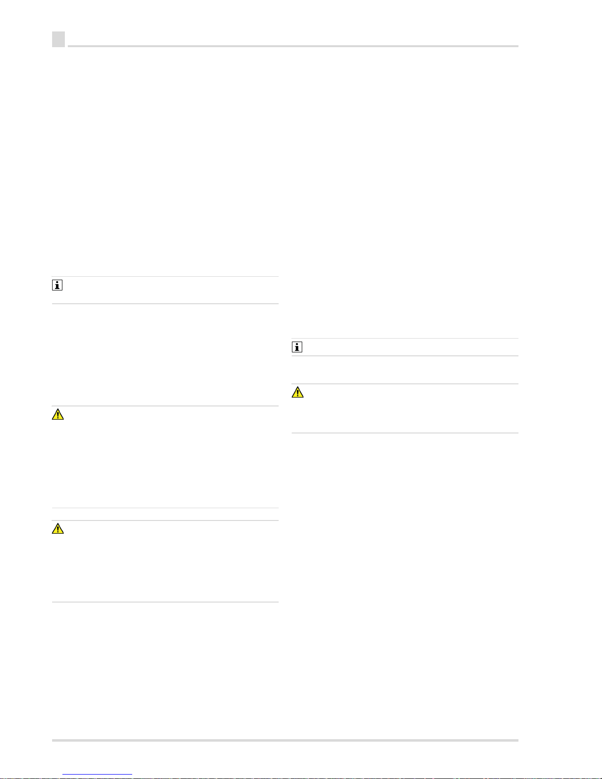
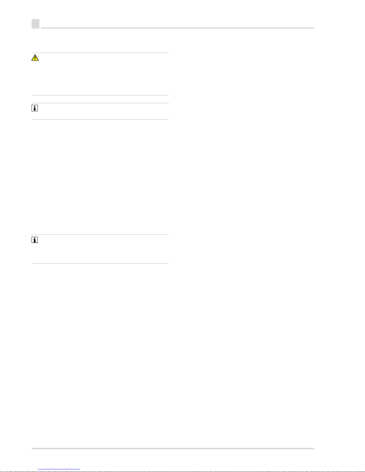
4. Insert the new battery. Make sure the battery plug is
inserted correctly (see figure). The battery runtime is reset
when the battery is inserted.
5. Place the front part of the housing on the gas detector and
re-tighten the four screws on the rear part of the housing
(torque: 35 Ncm).
6. Turn on the gas detector.
A successful battery replacement is confirmed with a
vibration (5 s) when the gas detector is turned on.
Notice 160 is displayed after the start sequence (see
Section 6 on Page 10).
7. Confirm the notice with the [OK] button.
8. After the battery replacement, the sensor requires a warmup phase (see the sensor data sheet). The displayed
concentration flashes until the warm-up phase is complete.
1) A free version of the Dräger CC-Vision Basic PC software can be
downloaded at www.draeger.com/software
35 Ncm
00533742.eps
Page 15

Device settings
15
en
7.6 Replacing the dust and water filter
1. Place the special tool on the dust and water separator.
2. Press the lever on the special tool downward and then
remove the dust and water separator.
3. Insert a new dust and water separator. The dust and water
separator must click into place.
For special gases (ozone, phosgene), the entire front casing,
including the special diaphragm, must be replaced due to the
special diaphragm.
8 Device settings
Only trained and qualified personnel may change the device
settings.
8.1 Factory setting
The factory settings may differ for customised orders.
Sensor grille:
4 units
Order no.:
40 units
Order no.:
Pac 6xx0 83 26 853 83 26 857
Pac 8xx0 83 26 852 83 26 859
Front casing: Order no.:
Pac 8000 ozone 83 26 851
Pac 8000 phosgene 83 26 854
00633742.eps
Bump test mode Quick bump test
Vibration alarm On
Bump test interval Off
Operation signal On
D-Light On
Switch off Always
Data logger interval 1 min
Usage duration (user) Off
Page 16

16
Device settingsen
8.2 Alarm settings
Alarm Display Latching Acknowledgeable LED Horn Vibration
1)
Alarm 1 A1
Alarm 2 A2
STEL STEL
TWA TWA
Pre-alarm
2)
Main alarm
3)
Instrument alarm
1) The intensity of the vibration depends on the temperature
2) After the initial battery pre-alarm, the battery’s life span amounts to between 1 day and 2 weeks under normal conditions of use. The life span is shorter at low
temperatures and/or in the event of alarms.
3) The gas detector automatically switches off after 10 s.
Page 17

Disposal
17
en
9 Disposal 10 Technical data
10.1 Gas detector
This product must not be disposed of as household
waste. This is indicated by the adjacent symbol. You
can return this product to Dräger free of charge. For
information please contact the national marketing
organizations or Dräger.
Batteries must not be disposed of as household waste.
This is indicated by the adjacent symbol. Dispose of
batteries at battery collection centers as specified by
the applicable regulations.
Ambient conditions during operation
Temperature
(temperature depending
on the sensor)
Up to -30 °C ... +55 °C
(briefly up to 1 h -40 °C ...
+55 °C)
Humidity 10 ... 90 % r.h., non-condensing
Pressure 700 ... 1300 hPa
Ambient conditions during storage:
Temperature 0 ... 40 °C
Humidity 30 ... 80 % r.h., non-condensing
Typ. battery lifetime (under normal conditions):
24 h operation/day,
1 min alarm/day
24 months
O
2
sensor: 10 months
Dual sensors (without O2):
22 months
Alarm volume approx. 90 dBA at a distance of
30 cm
Dimensions (not including
clip)
64 x 84 x 20 mm
Weight approx. 106 g (113 g with clip)
Degree of protection IP 68
Page 18

18
Technical dataen
10.2 Technical data of the sensors and the measuring device settings for Pac 6000/6500
CO-LC H
2
S-LC O
2
SO
2
Measuring range 0 ... 1999 ppm 0...100ppm 2 ... 25 Vol% 0...100ppm
Calibration gas concentration 50 ppm 20 ppm 18 Vol% 10 ppm
Temperature range, operation -40 ... 50 °C
-40 ... 122 °F
-40 ... 50 °C
-40 ... 122 °F
-40 ... 50 °C
-40 ... 122 °F
-30 ... 50 °C
-22 ... 122 °F
Alarm threshold A1
1)
1) Observe special, customer-requested settings. Device parameters can be changed with the Dräger CC-Vision Basic PC software.
30 ppm 5 ppm 19 Vol%
2)
2) For O
2
, A1 is the lower alarm threshold for displaying oxygen deficiency.
1 ppm
Acknowledgeable -
Latching
-
- -
Alarm threshold A2
1)
60 ppm 10 ppm 23 Vol% 2 ppm
Acknowledgeable - - - -
Latching
TWA threshold value
1) 3)
3) Not applicable for Pac 6000.
30 ppm 10 ppm - 1 ppm
STEL threshold value
1) 3)
60 ppm 10 ppm - 1 ppm
Mean value period 15 min 15 min - 15 min
Measurement accuracy
Zero point: ±2 ppm ±0.1 ppm ±0.2 Vol% ±0.1 ppm
Sensitivity: [% of the measured value] ±2 ± 5 ± 1 ±2
Long-term drift (20 °C)
Zero point: ±2 ppm/a ±0.2 ppm/a ±0.5 Vol%/a ±1 ppm/a
Sensitivity: [% of measured value/year] ±3 ±5 ±1 ±2/month
Sensor item number
4)
4) The sensors have a limited life span. Excessive storage periods compromise the operational life time of the sensors. The adequate temperature range for storage is 0 ... 35 °C (32 ... 95 °F).
68 13 210 68 11 525 68 10 881 68 10 885
Sensor data sheet item number 90 33 454 90 23 970 90 23 820 90 23 919
Page 19

Technical data
19
en
10.3 Technical data of the sensors and the measuring device settings for Pac 8000
NH
3
PH
3
HCN NO NO
2
-LC CO
2
Measuring range 0...300ppm 0...20ppm 0 ... 50 ppm 0 ... 200 ppm 0 ... 50 ppm 0...5Vol%
Calibration gas concentration 50 ppm in N
2
0.5 ppm in N
2
10 ppm in N
2
50 ppm in N
2
5ppm inN
2
2.5 Vol% in air
Temperature range, operation -30 ... 50 °C
-22 ... 122 °F
-20 ... 50 °C
-4 ... 122 °F
-20 ... 50 °C
-4 ... 122 °F
-40 ... 50 °C
-40...122°F
-30 ... 50 °C
-22 ... 122 °F
-20 ... 40 °C
-4 ... 104 °F
Alarm threshold A1
1)
1) Observe special, customer-requested settings. Device parameters can be changed with the Dräger CC-Vision Basic PC software.
50 ppm 0.1 ppm 10 ppm 25 ppm 0.5 ppm 0.5 Vol%
Acknowledgeable
Latching - - - - - -
Alarm threshold A2
1)
100 ppm 0.2 ppm 20 ppm 50 ppm 1ppm 1Vol%
Acknowledgeable - - - - - -
Latching
TWA threshold value
1)
20 ppm 0.1 ppm 1.9 ppm 25 ppm 0.5 ppm 0.5 Vol%
STEL threshold value
1)
40 ppm 0.1 ppm 3.8 ppm 50 ppm 1ppm 2Vol%
Mean value period 15 min 15 min 15 min 15 min 15 min 15 min
Measurement accuracy
Zero point: ±4 ppm ±0.02 ppm ±0.5 ppm ±0.3 ppm ±0.02 ppm ±0.3 Vol%
Sensitivity: [% of the measured value] ±3 ±2 ±5 ±3 ±3 ±20
Long-term drift (20 °C)
Zero point: ±5 ppm/a ±0.05 ppm/a ±2 ppm/a ±0.3 ppm/a ±0.04 ppm/a ±0.2 Vol%/a
Sensitivity:
[% of measured value/month
]
±2 ±2 ±5 ±2 ±2 ±15
Sensor item number
2)
2) The sensors have a limited life span. Excessive storage periods compromise the operational life time of the sensors. The adequate temperature range for storage is 0 ... 35 °C (32 ... 95 °F).
68 10 888 68 10 886 68 10 887 68 11 545 68 12 600 68 10 889
Sensor data sheet item number 90 23 922 90 23 920 90 23 921 90 33 091 90 33 093 90 23 923
Page 20

20
Technical dataen
Cl
2
OV
1)
1) Only for ethylene oxide.
OV-A
1)
Ozone Phosgene
Measuring range 0 ... 20 ppm 0...200ppm 0 ... 200 ppm 0 ... 10 ppm 0 ... 10 ppm
Calibration gas concentration 5ppm inN
2
20 ppm in N
2
20 ppm in N
2
0.5 ... 9 ppm O
3
3.8 ... 9 ppm
Temperature range, operation -30 ... 50 °C
-22...122°F
-20 ... 50 °C
-4 ... 122 °F
-20 ... 50 °C
-4 ... 122 °F
-20 ... 50 °C
-4 ... 122 °F
-20 ... 35 °C
-4 ... 99 °F
Alarm threshold A1
2)
2) Observe special, customer-requested settings. Device parameters can be changed with the Dräger CC-Vision Basic PC software.
0.5 ppm 10 ppm 10 ppm 0.1 ppm 0.1 ppm
Acknowledgeable
Latching - - - - -
Alarm threshold A2
1)
1ppm 20 ppm 20 ppm 0.2 ppm 0.2 ppm
Acknowledgeable - - - - -
Latching
TWA threshold value
1)
0.5 ppm - - 0.1 ppm 0.1 ppm
STEL threshold value
1)
0.5 ppm - - 0.1 ppm 0.1 ppm
Mean value period 15 min - - 15 min 15 min
Measurement accuracy
Zero point: ±0.05 ppm ±3 ppm ±5 ppm ±0.02 ppm ±0.01 ppm
Sensitivity: [% of the measured value] ±2 ±5 ±20 ±3 ±10
Long-term drift (20 °C)
Zero point: ±0.2 ppm/a ±5 ppm/a ±5 ppm/a ±0.02 ppm/a ±0.2 ppm/a
Sensitivity:
[% of measured value/month
] ±2 ±2 ±3 ±2 ±2
Sensor item number
3)
3) The sensors have a limited life span. Excessive storage periods compromise the operational life time of the sensors. The adequate temperature range for storage is 0 ... 35 °C (32 ... 95 °F).
68 10 890 68 11 530 68 11 535 68 11 540 68 12 005
Sensor data sheet item number 90 23 924 90 23 994 90 23 995 90 33 259 90 23 924
Page 21

Technical data
21
en
10.3.1 Sensors for Pac 8500 DUAL
H
2
S LC / CO LC O
2
/ CO-LC CO H
2
-CP
Measuring range 0 ... 100 ppm H
2
S
0 ... 2000 ppm CO
0...25Vol% O
2
0 ... 2000 ppm CO
0 ... 2000 ppm
Calibration gas concentration 5 ... 90 ppm H
2
S
20 ... 450 ppm CO
12 ... 20 Vol% O
2
20 ... 1800 ppm CO
1000 ppm H
2
20 ... 1800 ppm CO
Temperature range, operation -40 ... 50 °C
-40...122°F
-40 ... 50 °C
-40 ... 122 °F
-40 ... 50 °C
-40...122°F
Alarm threshold A1
1)
1) Observe special, customer-requested settings. Device parameters can be changed with the Dräger CC-Vision Basic PC software.
5 ppm H
2
S
30 ppm CO
19 O
2
30 CO
30 ppm
Acknowledgeable O
2
:
-
CO:
Latching - O
2
:
CO: -
-
Alarm threshold A2
1)
10 ppm H
2
S
60 ppm CO
23 O
2
60 CO
60 ppm
Acknowledgeable - O
2
:
-
CO: -
-
Latching O
2
:
CO:
TWA threshold value
1)
5 ppm H
2
S
30 ppm CO
-
30 ppm CO
-
30 ppm CO
STEL threshold value
1)
10 ppm H
2
S
60 ppm CO
-
60 ppm CO
-
60 ppm CO
Mean value period 15 min 15 min 15 min
Measurement accuracy
Zero point: H
2
S: 0.4 ppm
CO: 2ppm
O
2
±0.4 Vol%
CO: ±2 ppm
±6 ppm
Sensitivity: [% of the measured value] H
2
S: ±5
CO: ±2
O
2
±1
CO: ±2
±2
Long-term drift (20 °C)
Zero point: H
2
S: ±0.2 ppm/a
CO: ±2 ppm/a
O
2
±0.5 Vol%/a
CO: ±2 ppm/a
±2 ppm/a
Sensitivity:
[% of measured value/year
] H
2
S: ±5
CO: ±3
O
2
±1
CO: ±3
±1/month
Sensor item number
2)
2) The sensors have a limited life span. Excessive storage periods compromise the operational life time of the sensors. The adequate temperature range for storage
is 0 ... 35 °C (32 ... 95 °F).
68 13 280 68 13 275 68 11 950
Sensor data sheet item number 90 33 511 90 33 510 90 23 924
Page 22

22
Technical dataen
10.3.2 Cross-sensitivities
Cross-sensitivity factors
4)
CO-LC H2S O
2
Acetylene 2 No effect -0.5
Ammonia No effect No effect No effect
Carbon dioxide No effect No effect -0.04
Carbon monoxide No effect No effect 0.2
Chlorine 0.05 -0.2 No effect
Ethane No effect No effect -0.2
Ethanol No effect No effect No effect
Ethylene No effect No effect -1
Hydrogen 0.35 No effect -1.5
Hydrogen chloride No effect No effect No effect
Hydrogen cyanide No effect No effect No effect
Hydrogen sulphide 0.03 No effect
Methane No effect No effect No effect
Nitrogen dioxide 0.05 -0.25 No effect
Nitric oxide 0.2 0.03 No effect
Propane No effect No effect No effect
Sulphur dioxide 0.04 0.1 No effect
Page 23

Page 24

Dräger Safety AG & Co. KGaA
Revalstraße 1
23560 Lübeck, Germany
Tel +49 451 882 0
Fax +49 451 882 20 80
www.draeger.com
90 33 742 - TH 4623.700
© Dräger Safety AG & Co. KGaA
Edition 01 - July 2017
Subject to alteration
 Loading...