

Page 1
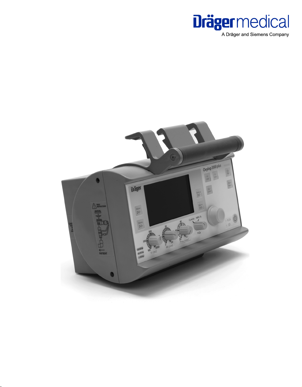
Instructions for Use
Oxylog 2000 plus
WARNING
For a full understanding of the performance characteristics of this device,
the user should carefully read this manual before use of the device.
Title
Emergency and Transport Ventilator
Software 1.n
Page 2

Working with these Instructions for Use
Working with these Instructions for Use
The title of the main chapter in the header line
helps with orientation and navigation.
The Instructions for Use combine text and illustrations, providing a comprehensive overview of the
system. The information is presented as sequential
steps of action, allowing the user to systematically
learn how to use the device.
The text provides explanations and instructs the
user step-by-step in the practical use of the
product, with short, clear instructions in
easy-to-follow sequences.
1 Consecutive numbers indicate the steps of
action, with the numbering restarting with "1" for
each new sequence of actions.
z Bullet points indicate individual actions or
different options for action.
– Dashes indicate the listing of data, options or
objects.
(A) Letters in parentheses refer to elements in the
relevant illustration.
The illustrations show the relationship between
the text and the device. Elements mentioned in the
text are highlighted. Unnecessary details are
omitted.
Schematic renderings of screen images guide the
user and allow to reconfirm actions performed. The
actual screen images differ in lock or in configuration.
A Letters denote elements referred to the text.
Trademarks
The Dräger Oxylog
mark of Dräger.
Definitions
WARNI NG
A WARNING statement provides important
information about a potentially hazardous situation which, if not avoided, could result in
death or serious injury.
CAUTION
A CAUTION statement provides important information about a potentially hazardous situation
which, if not avoided, may result in minor or moderate injury to the user or patient or in damage to
the equipment or other property.
NOTE
A NOTE provides additional information intended
to avoid inconvenience during operation.
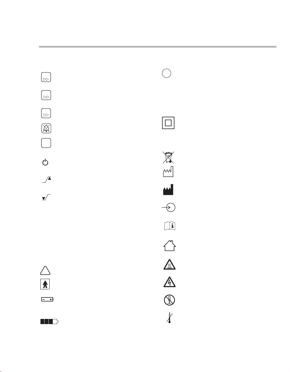
Abbreviations and Symbols
Please refer to "Abbreviations" on page 16 and
"Symbols" on page 17 for additional information.
®
name is a registered trade-
Typing conventions
Any text shown on the screen and any labeling on
the device are printed in bold and italics, for example PEEP, Air or Alarm Settings.
2
Instructions for Use Oxylog 2000 plus SW 1.n
Page 3

Contents
Contents
For Your Safety and that of Your Patients .5
General WARNINGS and CAUTIONS . . . . . . 7
Application . . . . . . . . . . . . . . . . . . . . . . . . . . 9
Intended use. . . . . . . . . . . . . . . . . . . . . . . . . . 10
Indications/Contraindications . . . . . . . . . . . . . 10
Environment of use. . . . . . . . . . . . . . . . . . . . . 10
System Overview . . . . . . . . . . . . . . . . . . . . . 11
Front panel with all options. . . . . . . . . . . . . . . 12
Available ventilation modes . . . . . . . . . . . . . . 14
Special modes . . . . . . . . . . . . . . . . . . . . . . . . 15
With monitoring. . . . . . . . . . . . . . . . . . . . . . . . 15
Abbreviations . . . . . . . . . . . . . . . . . . . . . . . . . 16
Symbols . . . . . . . . . . . . . . . . . . . . . . . . . . . . . 17
Operating Concept . . . . . . . . . . . . . . . . . . . . 19
Switch ON or OFF . . . . . . . . . . . . . . . . . . . . . 20
Ventilation controls . . . . . . . . . . . . . . . . . . . . . 21
Display operating controls . . . . . . . . . . . . . . . 22
Screen window structure . . . . . . . . . . . . . . . . 23
Assembly. . . . . . . . . . . . . . . . . . . . . . . . . . . . 27
Dead space . . . . . . . . . . . . . . . . . . . . . . . . . . 28
Assemble the reusable hose system . . . . . . . 29
Connect the disposable hose system. . . . . . . 31
Connecting the power supply . . . . . . . . . . . . . 32
Internal supply with rechargeable battery. . . . 32
Connecting the gas supply . . . . . . . . . . . . . . . 34
Hanging the Oxylog 2000 plus on standard rail sys-
tems . . . . . . . . . . . . . . . . . . . . . . . . . . . . . . . . 36
Getting Started . . . . . . . . . . . . . . . . . . . . . . . 37
Charging the battery. . . . . . . . . . . . . . . . . . . . 38
Determining the approximate pneumatic operating
time for the Oxylog 2000 plus. . . . . . . . . . . . . 39
Checking readiness for operation. . . . . . . . . . 40
Perform device check. . . . . . . . . . . . . . . . . . . 41
Preparation for use after system check . . . . . 43
Preparing ventilation mode . . . . . . . . . . . . . . 47
VC-CMV / VC-AC . . . . . . . . . . . . . . . . . . . . . 48
VC-SIMV (optional PS) . . . . . . . . . . . . . . . . . 50
SpnCPAP (optional PS). . . . . . . . . . . . . . . . . 52
O2 AirMix or 100% O2 . . . . . . . . . . . . . . . . . 55
Calibration . . . . . . . . . . . . . . . . . . . . . . . . . . . 56
Screen brightness . . . . . . . . . . . . . . . . . . . . . 56
Volume loudness. . . . . . . . . . . . . . . . . . . . . . 56
Shutdown . . . . . . . . . . . . . . . . . . . . . . . . . . . 57
Alarms . . . . . . . . . . . . . . . . . . . . . . . . . . . . . 59
Types of alarms. . . . . . . . . . . . . . . . . . . . . . . 60
In the event of an alarm. . . . . . . . . . . . . . . . . 61
Setting alarm limits . . . . . . . . . . . . . . . . . . . . 63
Monitoring . . . . . . . . . . . . . . . . . . . . . . . . . . 65
Displaying the airway pressure . . . . . . . . . . . 66
Displaying MVe and VTe . . . . . . . . . . . . . . . . 66
Displaying O2 values. . . . . . . . . . . . . . . . . . . 66
Displaying other measured values . . . . . . . . 67
Configuration. . . . . . . . . . . . . . . . . . . . . . . . 69
Set configuration parameters / display information
70
Displaying configuration and information . . . 71
Customer Service Mode . . . . . . . . . . . . . . . . 72
Problem Solving . . . . . . . . . . . . . . . . . . . . . 79
Alarm - Cause - Remedy. . . . . . . . . . . . . . . . 80
Messages in the alarm window . . . . . . . . . . . 80
Messages in the information window . . . . . . 84
Error messages during the device check . . . 85
Cleaning, Disinfection and Sterilization . . 87
Disassembly . . . . . . . . . . . . . . . . . . . . . . . . . 88
Reprocessing procedure . . . . . . . . . . . . . . . . 91
Maintenance. . . . . . . . . . . . . . . . . . . . . . . . . 95
Maintenance intervals . . . . . . . . . . . . . . . . . . 96
Operation. . . . . . . . . . . . . . . . . . . . . . . . . . . . 45
Starting operation . . . . . . . . . . . . . . . . . . . . . . 46
Instructions for Use Oxylog 2000 plus SW 1.n 3
Disposal . . . . . . . . . . . . . . . . . . . . . . . . . . . . 99
Safety information . . . . . . . . . . . . . . . . . . . . . 100
Disposal of batteries . . . . . . . . . . . . . . . . . . . 100
Page 4

Contents
Disposal of the medical device. . . . . . . . . . . . 100
Disposal of the disposable hose system . . . . 101
Technical Data . . . . . . . . . . . . . . . . . . . . . . . 103
Ambient conditions . . . . . . . . . . . . . . . . . . . . . 104
Settings . . . . . . . . . . . . . . . . . . . . . . . . . . . . . 105
Performance data. . . . . . . . . . . . . . . . . . . . . . 106
Measured value display . . . . . . . . . . . . . . . . . 107
Monitoring. . . . . . . . . . . . . . . . . . . . . . . . . . . . 108
Operating data . . . . . . . . . . . . . . . . . . . . . . . . 109
Device specifications . . . . . . . . . . . . . . . . . . . 111
Materials used . . . . . . . . . . . . . . . . . . . . . . . . 112
Technical Documentation for the Oxylog 2000 plus
according to EMC standard IEC/EN 60601-1-2 113
Principles of Operation . . . . . . . . . . . . . . . . 117
Ventilation modes. . . . . . . . . . . . . . . . . . . . . . 118
Functional description . . . . . . . . . . . . . . . . . . 121
List of Accessories . . . . . . . . . . . . . . . . . . . 123
Index . . . . . . . . . . . . . . . . . . . . . . . . . . . . . . . 125
4
Instructions for Use Oxylog 2000 plus SW 1.n
Page 5

For Your Safety and that of Your Patients
For Your Safety and that of Your Patients
Strictly follow these Instructions for Use
WARNING
Any use of the medical device requires full
understanding and strict observation of all
portions of these Instructions for Use. The
medical device is only to be used for the purpose specified under "Intended use"
on page 10 and in conjunction with appropriate patient monitoring.
Strictly observe all WARNING and CAUTION
statements throughout these Instructions for
Use and all statements on medical device
labels.
Maintenance
WARNING
The medical device must be inspected and
serviced regularly by properly trained service
personnel.
Repair of the device may also only be carried
out by properly trained service personnel.
Dräger Medical recommends that a service
contract be obtained with DrägerService and
that all repairs also be carried out by them.
Dräger Medical recommends that only authentic Dräger Medical repair parts be used for
maintenance. Otherwise, the proper functioning of the medical device may be
compromised.
Refer to the chapter "Maintenance"
on page 95 for additional information.
Accessories
WARNING
Only the accessories indicated on the list of
accessories have been tested and approved
to be used with the medical device. Accordingly, it is strongly recommended that only
these accessories be used in conjunction with
the specific medical device. Otherwise, the
correct functioning of the medical device may
be compromised.
WARNING
Any connected devices, or combination of
devices, not complying with the requirements
mentioned in these Instructions for Use may
compromise the correct functioning of the
medical device. Prior to operating the medical
device, consult the respective documentation
and Instructions for Use of all connected
devices or combination of devices.
Not for use in explosion hazard areas
WARNING
This medical device is neither approved nor
certified for use in areas where combustible or
explosive gas mixtures are likely to occur.
Safe connection with other electrical equipment
WARNING
Electrical connections to equipment, which
are not listed in these Instructions for Use,
should only be made following consultation
with the respective manufacturers. Equipment
malfunction may result as well as risk of
patient injury.
Instructions for Use Oxylog 2000 plus SW 1.n 5
Page 6

For Your Safety and that of Your Patients
Patient safety
The design of the medical device, the accompanying literature, and the labeling on the medical
device are based on the assumption that the purchase and use of the equipment are restricted to
trained professionals, and that certain inherent
characteristics of the medical device are known to
the trained operator. Instructions, warnings, and
caution statements are limited, therefore, largely to
the specifics of the Dräger design.
This publication excludes references to various
hazards which are obvious to a medical professional and operator of this medical device, to the
consequences of medical device misuse, and to
potentially adverse effects in patients with abnormal conditions.
Medical device modification or misuse can be dangerous.
CAUTION
Have a supply of extra batteries available.
Patient monitoring
Functional safety
The essential performance of the Oxylog 2000 plus
is defined as:
Accuracy of the delivery of ventilation to the patient
or generation of a technical alarm condition.
The operators of the medical device are responsible for choosing appropriate safety monitoring that
supplies adequate information on medical device
performance and patient condition.
Patient safety may be achieved through a wide
variety of means ranging from electronic surveillance of medical device performance and patient
condition, to simple, direct observation of clinical
signs.
The responsibility for the selection of the best level
of patient monitoring lies solely with the medical
device operator.
6
Instructions for Use Oxylog 2000 plus SW 1.n
Page 7

General WARNINGS and CAUTIONS
For Your Safety and that of Your Patients
The following WARNINGS and CAUTIONS apply to
general operation of the device. WARNINGS and
CAUTIONS specific to subsystems or particular
features appear with those topics in later sections
of the manual.
Note on EMC/ESD risk for the device function
General information on electromagnetic compatibility (EMC) pursuant to international EMC standard
IEC 60601-1-2:
Electromedical devices are subject to special precautionary measures concerning electromagnetic
compatibility (EMC) and must be installed and put
into operation in accordance with the EMC information. Refer to section "Technical Documentation for
the Oxylog 2000 plus according to EMC standard
IEC/EN 60601-1-2" on page 113.
Portable and mobile RF communications equipment can affect medical electrical equipment.
WARNING
Ventilation monitoring is mandatory at all
times! Whenever a patient is connected to the
ventilator, constant attention by qualified
medical staff is required in order to provide
immediate corrective action in case of a
malfunction.
The operator shall not rely on the built-in
monitoring of the ventilator only and must
always assume full responsibility for proper
ventilation and patient safety in all situations.
WARNING
Keep a manual resuscitation bag available!
If a failure is detected in the ventilator and its
life-support functions can no longer be guaranteed (e.g. in case of a power failure or interruption in the medical gas supply), ventilation
must be started without delay with an independent ventilation device (resuscitation bag)
– using PEEP and/or increased inspired O
concentration as necessary.
WARNING
Always use officially approved gas cylinders
and pressure regulators that comply with all
applicable regulations.
WARNING
For proper ventilation, always consider the
dead space of the total ventilation circuit when
setting ventilation parameters,
especially when applying small tidal volumes.
WARNING
Ventilation with increased oxygen concentra-
tions may be harmful to the patient. Oxygen
must be administered by medical professionals only.
2
Installing accessories
CAUTION
Installations to the basic device must be done in
accordance with the Instructions for Use of the
basic device. Make sure that the connection is
securely fitted onto the basic device system.
Strictly follow the Assembly Instructions and
Instructions for Use.
Instructions for Use Oxylog 2000 plus SW 1.n 7
Page 8

For Your Safety and that of Your Patients
Instructions for Use only available once
CAUTION
Only one copy of the Instructions for Use is
included in the clinical package and should therefore be kept in an accessible location for users.
8
Instructions for Use Oxylog 2000 plus SW 1.n
Page 9

Application
Intended use . . . . . . . . . . . . . . . . . . . . . . . . . 10
Indications/Contraindications. . . . . . . . . . . 10
Environment of use . . . . . . . . . . . . . . . . . . . 10
Intended use . . . . . . . . . . . . . . . . . . . . . . . . . 10
Indications/Contraindications. . . . . . . . . . . 10
Environment of use . . . . . . . . . . . . . . . . . . . 10
Application
Instructions for Use Oxylog 2000 plus SW 1.n 9
Page 10

Application
Intended use
The Oxylog® 2000 plus is a time-cycled, volume
controlled emergency and transport ventilator with
pressure support for patients requiring mandatory
or assisted ventilation with a tidal volume of 100 mL
upwards.
For use by and under the supervision of trained
health care professionals.
Indications/Contraindications
For patients requiring a tidal volume of 100 mL
upwards.
WARNING
The Oxylog 2000 plus ventilator may only be
used under the supervision of qualified medical personnel in order to be able to provide
immediate corrective action in case of a malfunction.
Environment of use
For use in the following environments:
– Mobile use for emergency patients, for outdoor
and indoor environments.
– During transport in ambulances or aircraft,
including helicopters.
– In accident and emergency departments.
– When moving ventilated patients around the
hospital.
– In the recovery room.
10
WARNI NG
Do not use the equipment in hyperbaric
chambers!
The device may malfunction, causing danger
to the patient.
WARNI NG
Do not use the equipment in conjunction with
magnetic resonance imaging (MRI, NMR, NMI).
The device may malfunction, causing danger
to the patient.
Instructions for Use Oxylog 2000 plus SW 1.n
Page 11

System Overview
Front panel with all options. . . . . . . . . . . . . 12
Side view, right . . . . . . . . . . . . . . . . . . . . . . . . 13
Rear view . . . . . . . . . . . . . . . . . . . . . . . . . . . . 13
Reusable hose system . . . . . . . . . . . . . . . . . . 14
Disposable hose system. . . . . . . . . . . . . . . . . 14
Available ventilation modes . . . . . . . . . . . . 14
Special modes . . . . . . . . . . . . . . . . . . . . . . . 15
With monitoring . . . . . . . . . . . . . . . . . . . . . . 15
Abbreviations . . . . . . . . . . . . . . . . . . . . . . . . 16
Symbols. . . . . . . . . . . . . . . . . . . . . . . . . . . . . 17
System Overview
Instructions for Use Oxylog 2000 plus SW 1.n 11
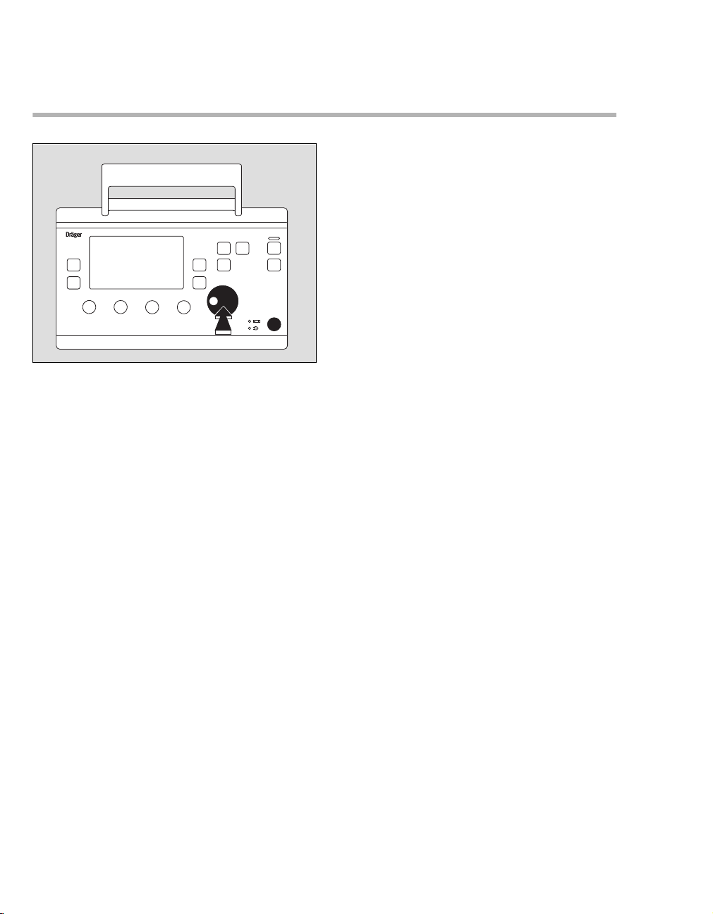
Page 12
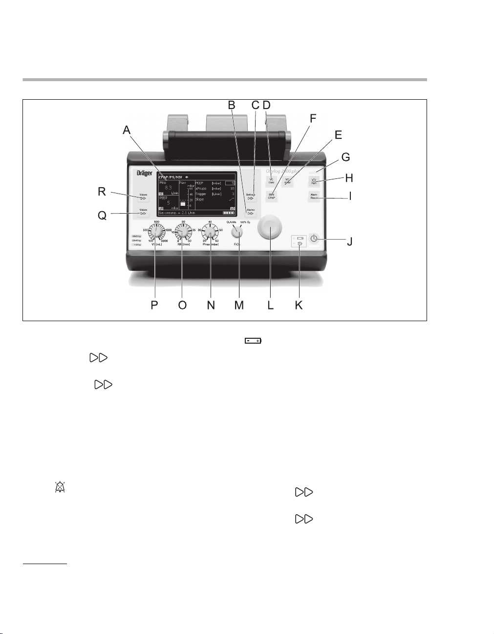
System Overview
Front panel with all options
A Screen with screen pages for the specific
application
B Key Alarms for setting and displaying
alarm limits
C Key Settings for setting other
ventilation parameters on the screen
D Key for ventilation modes VC-CMV / VC-AC
E Key for ventilation modes VC-SIMV (PS)*
F Key for ventilation modes SpnCPAP (PS)*
G Red and yellow lights (LEDs) as alarm
indicators
H Key to suppress the audible alarm for
2 minutes
I Key Alarm Reset for acknowledging alarm
messages
J Start / Standby key
* VC-SIMV/PS and SpnCPAP/PS are optional features.
O
12
K Display symbols for the power supply
Charge status of the internal battery
N Mains power supply connected
L Central rotary knob for making selections /
settings and for confirming these
M Control knob for setting O
2
FiO
N Control knob for setting the maximum
inspiratory pressure Pmax
O Control knob for setting the ventilation respira-
tory rate RR
P Control knob for setting the tidal volume VT
Q Key Values to select the displayed mea-
sured values
R Key Values to select the displayed mea-
sured MVe or VTe values
Instructions for Use Oxylog 2000 plus SW 1.n
2 AirMix or 100% O2
043
Page 13
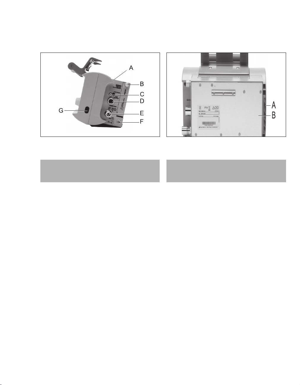
System Overview
Side view, right
A Emergency air intake
WARNING
Do not block the emergency air intake. This
may result in ventilator malfunction.
B Screw to secure the battery compartment cover
C Gas outlet for flow measuring hoses
D Gas outlet for ventilation hose
E Connector for medical gas hose
F Socket for DC supply
G Window for Infrared Data Association (IrDA)
interface
Rear view
041
A Filter cartridge for intake of ambient air
CAUTION
Do not block the air intake. This may result in
ventilator malfunction.
B Rating plate
042
Instructions for Use Oxylog 2000 plus SW 1.n 13
Page 14
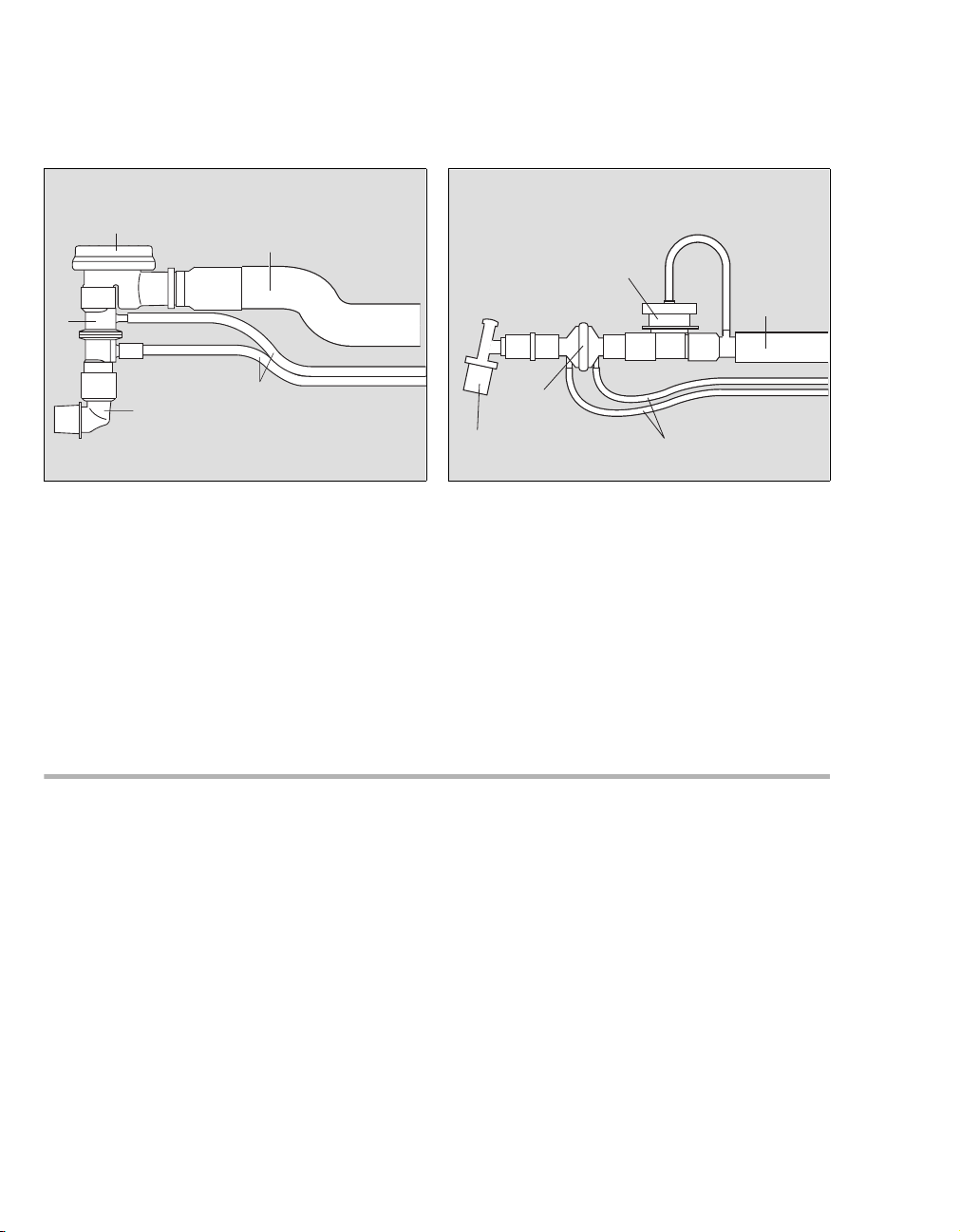
System Overview
Reusable hose system
A
B
E
D
A Breathing valve
B Ventilation hose
C Flow and pressure measuring hoses
D Angled connector
E Flow sensor
C
Disposable hose system
A
D
E
001
A Breathing valve
B Ventilation hose
C Flow and pressure measuring hoses
D Flow sensor
E Angled connector
C
B
002
Available ventilation modes
– VC-CMV / VC-AC
Volume Controlled - Controlled Mechanical
Ventilation with PEEP.
Volume Controlled - Assist Control with PEEP.
– VC-SIMV (PS)
Volume Controlled - Synchronized Intermittent
Mandatory Ventilation with PEEP
(Optionally with Pressure Support).
Procedure for weaning patients off the ventilator
after they have started spontaneous breathing.
14
– SpnCPAP (PS)
Continuous Positive Airway Pressure
(Optionally with Pressure Support)
Spontaneous breathing with positive airway
pressure.
Instructions for Use Oxylog 2000 plus SW 1.n
Page 15

Special modes
In the ventilation mode SpnCPAP, two special
modes are available.
– Apnea Ventilation
To switch over automatically to volume-controlled mandatory ventilation if spontaneous
breathing stops.
– NIV
For mask ventilation to support non-invasive
ventilation of spontaneously breathing patients
with leakage compensation.
With monitoring
– Airway pressure Paw.
– Expiratory minute volume MVe.
– Apnea.
– Respiratory rate: High respiratory rate alarm.
System Overview
Instructions for Use Oxylog 2000 plus SW 1.n 15
Page 16

System Overview
Abbreviations
Abbreviation Explanation
bpm Breaths per minute
BTPS Body Temperature, Pressure
Saturated
Measured values referred to the conditions of the patient's lung, body
temperature 37
o
C, airway pressure,
water-vapor-saturated gas
C Lung compliance
EN 794-3 European standard for medical
ventilators, Part 3 "Emergency and
transport ventilators"
ESD Electrostatic discharge
∆Psupp Positive pressure above PEEP
FiO2 Fraction of inspiratory oxygen
FRC Functional Residual Capacity
HME Heat Moisture Exchange
I:E Relation inspiratory time to
expiratory time
IrDA Infrared Data Association
MVe Total expiratory minute volume
MVi Total inspiratory minute volume
spon Spontaneous minute volume
MV
NIV Non-invasive ventilation – mask ven-
tilation
2 AirMix Inspiratory gas mixture of O2 and
O
ambient air.
Paw Airway pressure
PEEP Positive end expiratory pressure
PIP Peak inspiratory pressure
Pinsp Inspiratory pressure
Pmax Maximum allowed inspiratory
pressure
Pmean Mean airway pressure
Pplat Plateau pressure
Abbreviation Explanation
PS Pressure Support, pressure assisted
spontaneous breathing
RF Radio Frequency
RR Respiratory Rate (frequency)
RRapn Respiratory Rate during apnea
ventilation
RRsp Spontaneous Respiratory Rate
Slope Speed of which inspiratory flow is
reached
SpnCPAP Continuous Positive Airway
Pressure
Spontaneous breathing with
continuous positive pressure
Tapn Time for apnea alarm
Te Expiratory time
Ti Inspiratory time
Tplat % Plateau time in % of inspiratory time
Taw Airway temperature
VC-AC Volume Controlled
Assist Control with PEEP
VC-CMV Volume Controlled
Controlled Mandatory Ventilation
VC-SIMV Volume Controlled
Synchronized Intermittent
Mandatory Ventilation
VTapn Tidal volume during apnea
ventilation
VT Tidal volume
VTe Expiratory tidal volume
VTi Inspiratory tidal volume
16
Instructions for Use Oxylog 2000 plus SW 1.n
Page 17
Symbols
System Overview
Symbol Explanation
Settings
Display screen window "Settings"
Alarms
Display screen window "Alarms"
Values
Display screen window measured
"Values"
Suppress audible alarm for
2 minutes
Alarm
Acknowledge alarms
Reset
Start / Standby key
Upper alarm limit only
Lower alarm limit only
! Advisory message
!! Caution message
!!! Warning message
!
Type BF applied part (body
Strictly follow the Instructions for
Use!
floating)
Charge status of the internal
battery
N Mains power supply connected
Battery charge
(example: three quarters full)
Symbol Explanation
E 4 10 R-02 XXXX
The device complies with UN
Regulation no. 10, revision 2 with
respect to EMC for use in motor
vehicles.
IPX4 Device protected from water
sprayed from all directions, limited
entrance allowed.
Class II equipment, device protected against electric shock with
additional safety precautions such
as double or reinforced insulations,
without protective earthing.
Do not dispose of the device as
municipal waste.
Manufacturing date
Manufacturer
DC input
Consult the instructions for use.
Indoor use only
Caution, hot surface!
Warning, dangerous voltage!
Do not open!
Temperature limitations
Instructions for Use Oxylog 2000 plus SW 1.n 17
Page 18

This page intentionally left blank
18 Instructions for Use Oxylog 2000 plus SW 1.n
Page 19

Operating Concept
Switch ON or OFF. . . . . . . . . . . . . . . . . . . . . 20
Switch ON. . . . . . . . . . . . . . . . . . . . . . . . . . . . 20
Switch OFF. . . . . . . . . . . . . . . . . . . . . . . . . . . 20
Ventilation controls . . . . . . . . . . . . . . . . . . . 21
Display operating controls . . . . . . . . . . . . . 22
Changing screen pages in the windows . . . . . 23
Screen window structure. . . . . . . . . . . . . . . 23
Switch ON or OFF. . . . . . . . . . . . . . . . . . . . . 20
Switch ON. . . . . . . . . . . . . . . . . . . . . . . . . . . . 20
Switch OFF. . . . . . . . . . . . . . . . . . . . . . . . . . . 20
Ventilation controls . . . . . . . . . . . . . . . . . . . 21
Display operating controls . . . . . . . . . . . . . 22
Changing screen pages in the windows . . . . . 23
Operating Concept
Screen window structure. . . . . . . . . . . . . . . 23
Instructions for Use Oxylog 2000 plus SW 1.n 19
Page 20
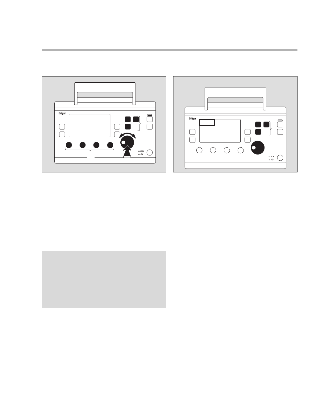
Operating Concept
Switch ON or OFF
Oxylog 2000 plus
B
A
Switch ON
z To switch ON, briefly press the O key (A).
Switch OFF
1 To switch OFF, hold down the O key (A) for
approximately 3 seconds.
2 Press the rotary knob (B) to confirm the switch
OFF process.
003
20
Instructions for Use Oxylog 2000 plus SW 1.n
Page 21
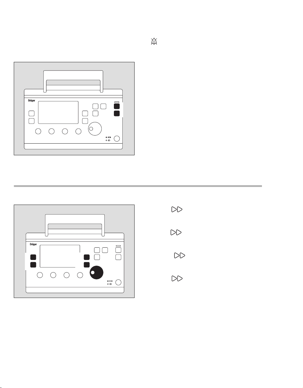
Ventilation controls
Operating Concept
Selecting the ventilation mode
Oxylog 2000 plus
A
C
A Keys for selecting the ventilation modes:
– VC-CMV / VC-AC
– VC-SIMV (optional PS)
– SpnCPAP (optional PS).
B Rotary knob.
C Ventilation parameter controls
– Inspiratory tidal volume VT
– Ventilation respiratory rate RR [/min],
– Maximum inspiratory pressure Pmax [mbar],
2 AirMix or 100% O2 FiO2.
– O
NOTE
Different ventilation modes and their parameters
can be set in the display window via the rotary
knob (e.g. Ti, PEEP, ∆Psupp, Pinsp).
– To select the parameter: turn rotary knob.
– To activate the parameter: press rotary knob.
– To set the value: turn rotary knob.
– To confirm the value: press rotary knob.
B
[mL],
Oxylog 2000 plus
C
A
B
004
z Press the appropriate ventilation mode key (A)
for approximately 3 seconds.
Or
1 Press the appropriate ventilation mode key (A).
2 Press the rotary knob (B) to confirm. The
selected ventilation mode will be activated.
3 The active ventilation mode is displayed in the
upper left corner of the display (C).
Refer to the section "Operation" on page 45 for
additional information on ventilation mode
setting.
005
Instructions for Use Oxylog 2000 plus SW 1.n 21
Page 22
Operating Concept
Routine and additional functions keys
Frequently used keys are positioned on the upper
right corner of the front panel:
Oxylog 2000 plus
A
B
Display operating controls
Oxylog 2000 plus
A
B
C
D
E
A key for suppressing the audible alarm for
2 minutes.
B Alarm Reset key for acknowledging alarm
messages.
006
A Values key; to change screen pages in
the "Measured Values" window, to display MVe
or VTe.
B Values key; to change screen pages in
the "Measured values" window, to display the
measured values.
C Settings key; to change screen pages in
the "Setting" window, to set other ventilation
parameters.
D Alarms key; to change screen pages in
the "Alarms" window, to set and display the
alarm limits.
007
E Central rotary knob for selecting and confirming
options on the display.
22
Instructions for Use Oxylog 2000 plus SW 1.n
Page 23
Changing screen pages in the windows
To advance to the next page in a screen window:
Settings and Alarms window:
1 Press the Settings key to display the
settings pages.
2 Press the Alarms key to display the
alarms pages.
Screen window structure
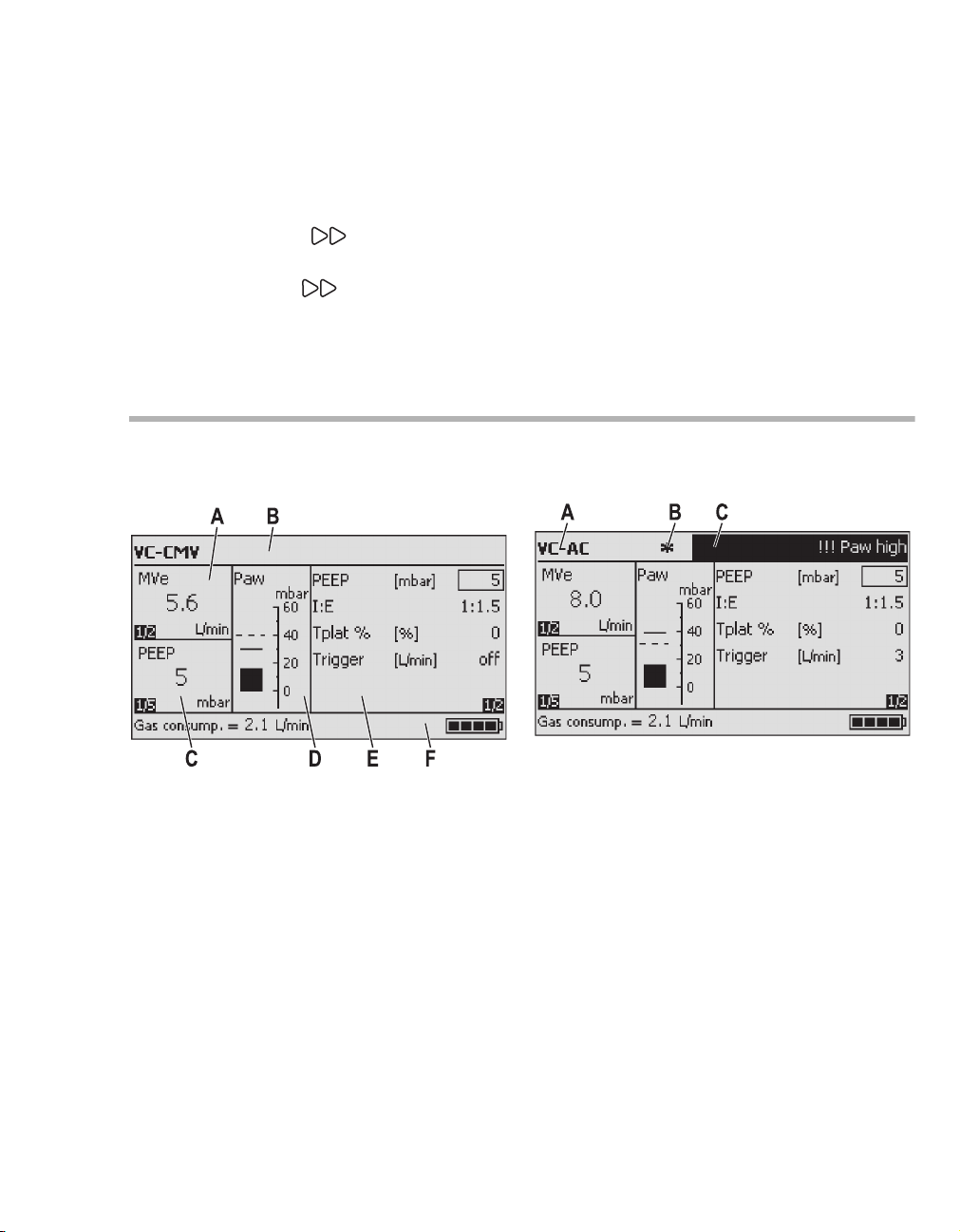
Operating Concept
Status and alarm messages window
A Ventilation mode.
A Measured MVe / VTe window.
B Status and alarm message window.
C Measured values window.
D Airway pressure bar graph.
E Settings and alarms window.
F Information window.
Instructions for Use Oxylog 2000 plus SW 1.n 23
B Trigger indicator.
C Alarm window.
Page 24
Operating Concept
MVe / VTe window
A Parameter measured.
B Measured value.
C Unit of measure.
D Page number.
To advance to the next page:
z Press the upper Values key.
Values window
To advance to the next page:
z Press the lower Values key.
Airway pressure bar graph
AB
C D
A Pmax alarm setting.
B Unit of measure scale.
C Pressure measurement of the previous breath.
D Pressure measurement of the current breath.
Alarms window
A Parameter measured.
B Measured value.
C Page number.
D Unit of measure.
24
A Menu for alarm limits and alarm parameters.
For detailed operating instructions, see "Setting
alarm limits" on page 63.
B Page number.
1st page of 2 available pages.
Instructions for Use Oxylog 2000 plus SW 1.n
Page 25
Operating Concept
To advance to the next page:
z Press the Alarms key.
Settings window
A Menu for setting supplementary ventilation
parameters in accordance with the desired ventilation mode:
–I:E
–Ti
–PEEP
– ∆Psupp
– Tapn
– Trigger
– Tplat %
– Slope
–NIV
– Brightness
– RRapn
–VTapn
1st page of 2 available pages.
B Page number.
Messages window
A Numeric values displayed when a control knob
is turned.
Instructions for Use Oxylog 2000 plus SW 1.n 25
Page 26
Operating Concept
Battery capacity indicator
A Battery capacity indicator (example: three quar-
ters full).
O2 consumption
A Actual gas consumption based on current
settings.
26
Instructions for Use Oxylog 2000 plus SW 1.n
Page 27

Assembly
Dead space . . . . . . . . . . . . . . . . . . . . . . . . . . 28
Assemble the reusable hose system . . . . . 29
Breathing valve assembly. . . . . . . . . . . . . . . . 29
When using a bacterial filter or HME . . . . . . . 30
Hose connections. . . . . . . . . . . . . . . . . . . . . . 30
Connect the disposable hose system . . . . 31
When using a bacterial filter or HME . . . . . . . 31
When changing the ventilation hose system . 31
Connecting the power supply . . . . . . . . . . . 32
Internal supply . . . . . . . . . . . . . . . . . . . . . . . . 32
Additional external power supply . . . . . . . . . . 32
Internal supply with rechargeable battery . 32
Replacing the battery . . . . . . . . . . . . . . . . . . . 32
Checking the charge of the battery. . . . . . . . . 32
Installing the battery . . . . . . . . . . . . . . . . . . . . 33
External power supply with DC/DC converter 33
External power supply from mains power (AC/DC
Power pack) . . . . . . . . . . . . . . . . . . . . . . . . . . 33
Assembly
Connecting the gas supply . . . . . . . . . . . . . 34
Supply from an O2 cylinder . . . . . . . . . . . . . . 35
Supply from a piped medical gas system . . . . 35
Hanging the Oxylog 2000 plus on standard rail
systems . . . . . . . . . . . . . . . . . . . . . . . . . . . . . 36
Instructions for Use Oxylog 2000 plus SW 1.n 27
Page 28

Assembly
Reusable or disposable hose systems can be used
with Oxylog 2000 plus. Please refer to the "List of
Accessories" section for ordering information.
NOTE
If the type of the hose system used is changed, the
device must be reconfigured. Refer to the
"Configuration" section for additional information.
Dead space
Dead space is an important aspect of ventilation
management:
Dead space ventilation is the portion of the respiratory system, in which no significant gas exchange
occurs. An increase of the proportion of dead space
to alveolar ventilation may lead to an increase of
the retention of carbon dioxide by the patient.
Dead space is present as a component of the
patient’s artificial airway and hose system. If the
volume of the mechanical dead space equals or
exceeds the volume of alveolar ventilation, the
patient may not be able to adequately evacuate
carbon dioxide. Therefore, it is important to properly manage the ventilation perfusion ratio to
ensure effective elimination of carbon dioxide
gases.
28
Instructions for Use Oxylog 2000 plus SW 1.n
Page 29
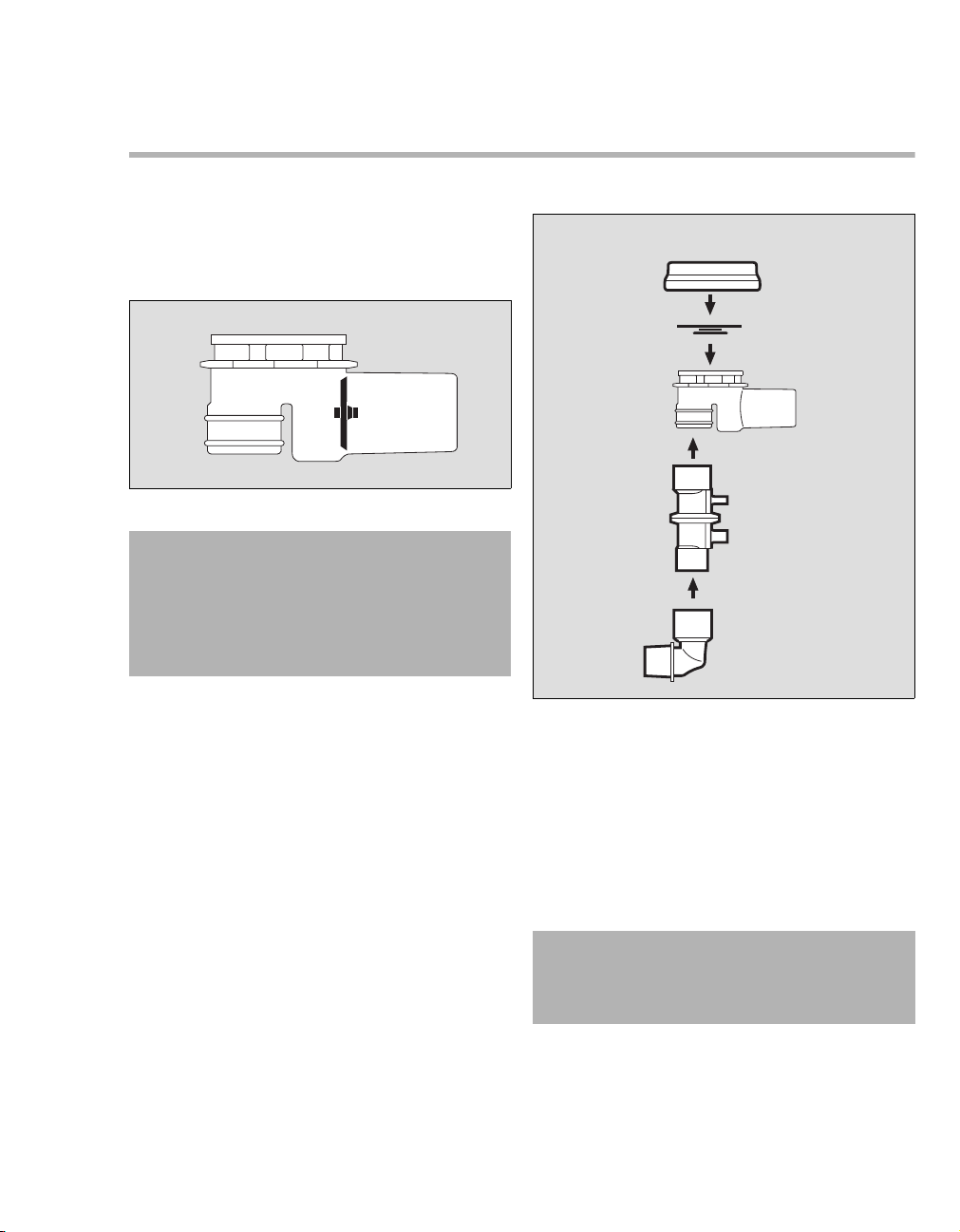
Assemble the reusable hose system
– Parts must always be sterilized before use!
Assembly
Breathing valve assembly
A
WARNING
The rubber disc (A) in the housing may not be
removed, damaged or bent, otherwise the
valve will not work properly and will endanger
the patient.
Risk of CO2 rebreathing.
A
B
008
C
D
1 Place the diaphragm (B) in the breathing valve.
Ensure that it is inserted correctly.
2 Fit the cover (A) and turn it approximately 90
clockwise to secure into position.
3 Push the flow sensor (C) into breathing valve.
Note the preferred position as indicated by the
groove.
4 Connect the angled adaptor (D) to the flow sen-
sor.
WARNING
Always use an angled adaptor. If the angled
adaptor is not used, the minute volume may
be measured incorrectly.
009
o
Instructions for Use Oxylog 2000 plus SW 1.n 29
Page 30
Assembly
When using a bacterial filter or HME
NOTE
When using a bacterial filter or HME, measured
flows may deviate from the expiratory flows, as
temperature and humidity of the gas are reduced.
z Connect the bacterial filter or HME to the angled
connector.
WARNING
Bacterial filters increase the exhalation resis-
tance and dead space volume of the ventilation system.
CAUTION
Do not use electrically conductive hoses!
Risk of electric shock.
This can endanger the patient.
A
B
010
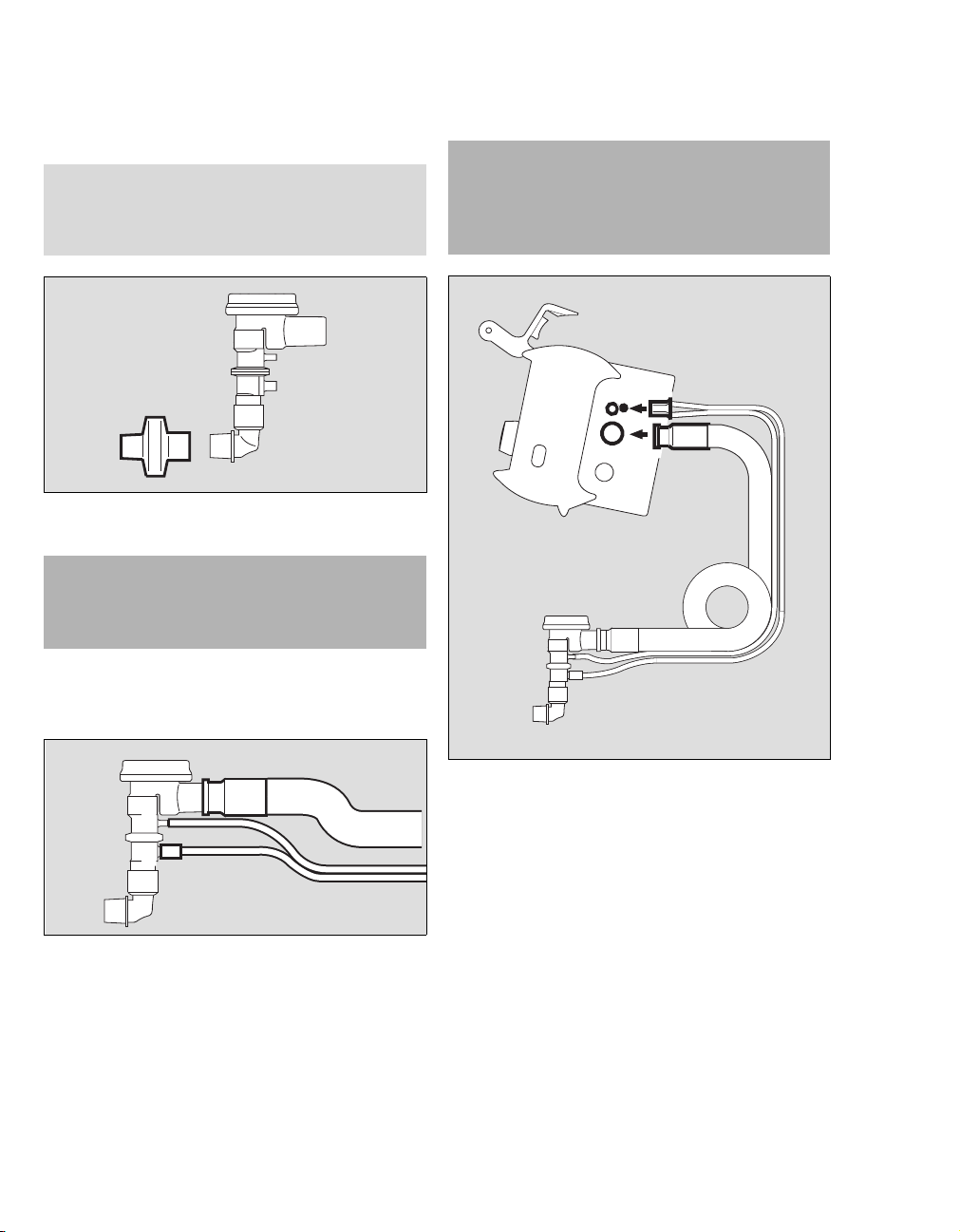
Hose connections
A
B
B
1 Connect the ventilation hose (A) to the
breathing valve.
2 Connect the flow measuring hoses (B) to the
nozzles on the flow sensor. Note the different
diameters.
30
012
3 Connect the flow measuring (A) hoses to the
Oxylog 2000 plus.
4 Connect the ventilation hose (B) to the gas out-
put on the Oxylog 2000 plus.
011
Instructions for Use Oxylog 2000 plus SW 1.n
Page 31

Connect the disposable hose system
WARNING
Do not use disposable hose systems other
than those on the "List of Accessories". The
minute volume may be measured incorrectly
and the device may malfunction.
A
B
C
Assembly
When using a bacterial filter or HME
NOTE
When using a bacterial filter or HME, measured
flows may deviate from the expiratory flows, as
temperature and humidity of the gas are reduced.
WARNING
Ensure that the flow measuring hoses are cor-
rectly positioned, otherwise the volume will be
measured incorrectly.
1 Connect the blue flow measuring hose (B) to
the blue gas outlet.
2 Connect the transparent flow measuring hose
(A) to the other gas outlet.
3 Connect the ventilation hose (C) to the gas out-
let on the Oxylog 2000 plus.
z Connect the bacterial filter or HME.
WARNING
Bacterial filters increase the exhalation resis-
tance and dead space volume of the ventilation equipment.
013
When changing the ventilation hose system
If the reusable ventilation hose system is to be used
instead of a disposable hose system or vice versa:
1 Have the nozzles on the device changed by
trained service specialists.
2 Reconfigure the device accordingly. Refer to
the "Customer Service Mode" on page 72 for
additional information.
014
Instructions for Use Oxylog 2000 plus SW 1.n 31
Page 32

Assembly
Connecting the power supply
The Oxylog 2000 plus is designed to operate on
power supplies with different voltages.
Internal supply
– With rechargeable battery (specified Smart
Battery, refer to the "Technical Data"
on page 103 for additional information).
Additional external power supply
To recharge the battery and to extend the electrical
operation time.
– DC voltage from the on-board power supply via
DC/DC converter or
– with AC/DC power pack
WARNI NG
A fully charged battery must always be
installed for safety reasons, even when operating from an external power supply!
To have a fully charged battery on hand, refer to the
"Getting started" section on page 38 for additional
information.
WARNI NG
Treatment of batteries:
– Do not throw into fire,
– Do not force open,
Danger of bodily injury.
Internal supply with rechargeable battery
Replacing the battery
1 Loosen the screw (C) on the battery compart-
2 Remove the battery cover.
3 Remove the battery (A) by pulling the tab.
ment cover (B) counterclockwise to release the
cover.
32
B
C
A
Checking the charge of the battery
z Press the button on the rechargeable battery.
The charge status is indicated as a percentage
by LEDs.
015
Instructions for Use Oxylog 2000 plus SW 1.n
Page 33

Installing the battery
1 Insert a fully charged battery into the battery
compartment.
2 Attach the connector at the bottom.
3 Turn the cover upwards.
4 Tighten the screw.
WARNING
The Oxylog 2000 plus will interrupt ventilation
when the battery is replaced while the device
is switched on and the external power supply
is not connected. Ventilation will resume with
the last values settings approximately 3 seconds after inserting the battery.
NOTE
It is recommended to use fully charged internal
batteries.
External power supply with DC/DC converter
Assembly
12 V DC
24 V DC
Oxylog 2000 plus
28 V DC
A
B
C
1 Plug the large connector (A) of the DC/DC con-
verter into the on-board supply.
2 Plug the small connector (B) into the DC nozzle
of the Oxylog 2000 plus.
3 When the Oxylog 2000 plus is connected to an
external supply, the indicator
and displays the internal battery status.
N (C) lights up
016
WARNING
Use only a specified DC/DC converter.
Otherwise the device can malfunction.
Refer to the "List of Accessories" on page 108
for additional information.
The DC/DC converter must be used to connect the
Oxylog 2000 plus to on-board supplies of different
voltages (12 V, 24 V, 28 V DC).
The voltage of the on-board supply may fluctuate,
depending on the amount of power required. The
supply voltage may fall below or exceed the range
permitted by the Oxylog 2000 plus. The on-board
voltage is converted into a constant DC voltage of
approximately 19 V DC by the DC/DC converter:
– When connected to an external power supply
(e.g. the on-board power supply of the vehicle),
the ventilator must always be connected via the
DC/DC converter, refer to the "List of Accessories" on page 123 for additional information.
Instructions for Use Oxylog 2000 plus SW 1.n 33
External power supply from mains
power
WARNING
Use only a specified AC/DC power pack
equipped with a correct mains plug.
Otherwise the device can malfunction.
Refer to the "List of Accessories" on page 108
for additional information.
WARNING
The AC/DC power pack may not be used
outdoors.
Risk of electric shock or equipment damage.
(AC/DC Power pack)
Page 34

Assembly
Oxylog 2000 plus
1 Connect the mains plug (A) to the mains outlet.
2 Connect the DC plug (B) to the DC outlet on the
A
Oxylog 2000 plus.
3 When the Oxylog 2000 plus is connected to an
external supply, the indicator
and displays the internal battery status.
N (C) lights up
C
B
Connecting the gas supply
Take care when handling O2:
WARNING
Secure O2 cylinders so they cannot fall over
and keep away from excessive heat.
Risk of explosion!
WARNING
Do not grease or lubricate O2 fittings, such as
cylinder valves and pressure reducers and do
not handle with greasy hands.
Risk of fire!
WARNING
Operate cylinder valves by hand and rotate
smoothly to prevent the risk of fire or
explosion.
Do not use tools.
017
WARNI NG
Only use medical grade oxygen that is dry and
free from dust and oil.
Contaminated gas can cause device
malfunction.
WARNI NG
Always provide adequate ventilation in order
to maintain ambient O2 concentration < 24%,
to prevent risk of fire.
WARNI NG
Always use extreme caution when using oxy-
gen, to prevent risk of fire.
WARNING
No smoking or open flames.
O
2 is combustible and can intensity fires.
34
Instructions for Use Oxylog 2000 plus SW 1.n
Page 35

Assembly
Supply from an O2 cylinder
WARNING
Only use compressed gas cylinders and pressure reducers, which comply with all applicable
regulations and have been approved.
1 Use a full O2 cylinder.
2 Connect the pressure reducer (270 to 600 kPa
delivery pressure, 500 kPa nominal pressure)
to the O
WARNING
Only use a pressure reducer with a relief valve at
the outlet to limit the delivery pressure to a maximum of 1000 kPa in case of a malfunction, to
prevent damage to the ventilator!
2 cylinder.
5 Rotate the cylinder valve (C) slowly and open
fully.
CAUTION
Do not connect flow control valves or flowmeters
in the gas supply to Oxylog 2000 plus.
The ventilator could malfunction!
WARNING
Always check the O2 pressure of cylinder
before use, to prevent insufficient oxylog supply during use.
Supply from a piped medical gas system
A
A
C
B
B
2
O
1 Connect the O2 medical gas hose (A) to the
Oxylog 2000 plus.
018
3 Connect the O2 medical gas hose (A) to the
Oxylog 2000 plus.
4 Connect the O
sure reducer (B).
Instructions for Use Oxylog 2000 plus SW 1.n 35
2 medical gas hose to the pres-
2 Connect the gas hose (B) to the O2 terminal unit
until the supply of O2 is confirmed.
019
Page 36

Assembly
Hanging the Oxylog 2000 plus on standard rail systems
The Oxylog 2000 plus can be hung on various rail
systems measuring up to 35 mm diameter by
means of the claw.
– Ensure that the rail is completely inserted in the
claw.
– To ensure optimal functioning of the claw, a dis-
tance of at least 25 mm between rail and wall is
required.
CAUTION
The Oxylog 2000 plus is only held by its own
weight when hung on a bar or rail. The Oxylog
2000 plus must be secured additionally when
being transported, otherwise vibrations may
cause accidental dislodgement.
36
Instructions for Use Oxylog 2000 plus SW 1.n
Page 37

Getting Started
Charging the battery . . . . . . . . . . . . . . . . . . 38
Indication of battery capacity / battery operation 38
Determining the approximate pneumatic oper-
ating time for the Oxylog 2000 plus . . . . . . 39
Checking readiness for operation . . . . . . . 40
Perform device check . . . . . . . . . . . . . . . . . 41
Connect the test lung . . . . . . . . . . . . . . . . . . . 41
Switch ON. . . . . . . . . . . . . . . . . . . . . . . . . . . . 41
Check connections . . . . . . . . . . . . . . . . . . . . . 42
System check . . . . . . . . . . . . . . . . . . . . . . . . . 42
Troubleshooting . . . . . . . . . . . . . . . . . . . . . . . 43
Preparation for use after system check . . . 43
Getting Started
Instructions for Use Oxylog 2000 plus SW 1.n 37
Page 38

Getting Started
Charging the battery
The actual screen display may differ in appearance
or configuration.
CAUTION
The ambient temperature must be between
0 and 35
o
C when charging the batteries.
When an external supply is available:
Oxylog 2000 plus
A
B
1 The green lamp N (B) lights up when the bat-
tery is actively charging.
2 A three colored indicator (A) lights up to
show the current charge status of the internal
battery:
– Green: when the battery has been fully
charged.
– Yellow: while the battery is being charged.
– Red: if a battery has not been inserted or a
technical failure occurred.
– Indicators (A) and (B) remain off while the
ventilator is being operated from the internal
battery.
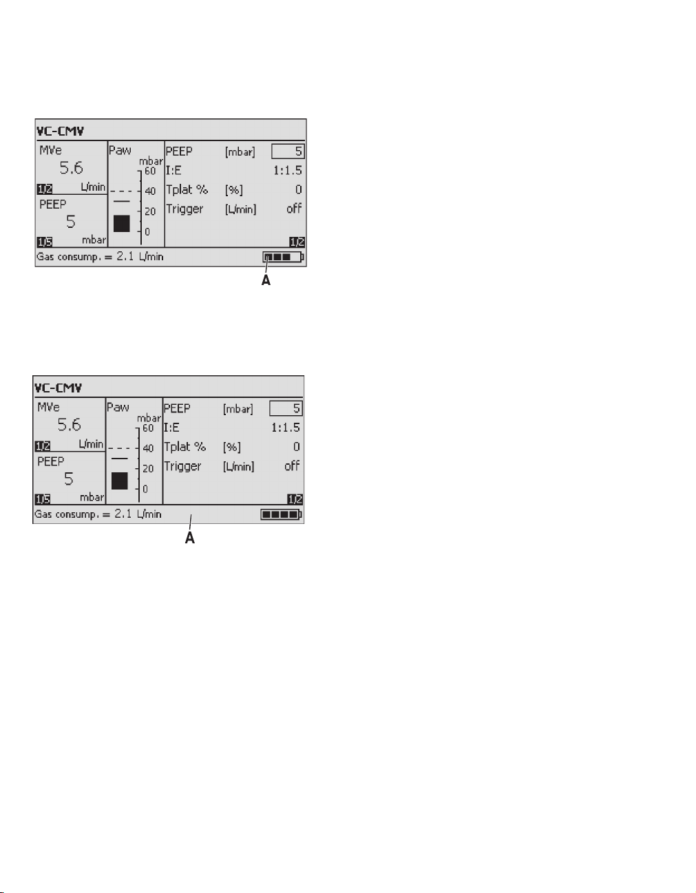
Indication of battery capacity / battery operation
The remaining capacity of the battery is indicated
by Oxylog 2000 plus in 25% increments in the lower
right section of the information window when power
is ON:
– when charging from an external power supply,
– as the battery is discharged during operation.
Example: 75% charge
020
– The accuracy of the battery capacity indicator
can vary, depending on the age and condition of
the battery. Refer to "Technical Data"
on page 103 for additional information.
– The capacity indication is overwritten if higher
priority messages are activated.
– Additional alarms can draw attention to the
remaining operating time of the battery.
– When operated via the rechargeable battery,
the brightness of the ventilator screen is
reduced in order to save power.
– The screen brightness is automatically
increased to maximum for one minute while
settings are being made.
An external battery charging station connected to
the mains supply can be used to charge an extra
battery. Refer to the "List of Accessories"
on page 123 for additional information.
38
Instructions for Use Oxylog 2000 plus SW 1.n
Page 39

Determining the approximate pneumatic operating time for the Oxylog 2000 plus
Getting Started
Example for supply of medical gas:
– Cylinder pressure measured on the pressure
gauge of the pressure reducer: 2000 kPa
– Liquid capacity of the O
2 cylinder: 2.1 L
Supply of medical gas:
2.1 L x 2000 kPa = approximately 420 L
Example for pneumatic operation time:
– VC-CMV mode, respiratory rate
10 breaths /min, VT = 1 L, O
2 = 100%
– Minute volume = 10 breaths /min x 1 L =
10 L/min
Operation time =
Calculated with average gas consumption of
*
ventilator: 0.5 L/min
Operation time = = approx. 40 minutes
Medical gas supply [L]
(MV +0.5*) [L/min]
420
10.5
Example:
2 consumption = 2.1 L/min
O
The pneumatic operation time increases when
Oxylog 2000 plus operates with O2 AirMix, as
ambient air is drawn into the device.
The amount of gas from the high-pressure supply,
which is currently being consumed, is indicated by
the Oxylog 2000 plus in the lower left section of the
information window in L/min. This display is overwritten when a higher priority message is activated.
Instructions for Use Oxylog 2000 plus SW 1.n 39
Page 40

Getting Started
Checking readiness for operation
– Whenever the ventilator has been serviced or
the ventilation hoses changed.
– At the latest every six months.
The following functions are checked with the menubased test:
– Gas supply present.
– Hose system / breathing valve connected and
OK.
– Alarm functions OK.
– Ventilation functions OK.
– Monitor functions OK.
Oxylog 2000 plus interrupts the test if a fault is
detected.
The relevant fault is indicated on the screen.
WARNING
The patient may be endangered if the above
device check is not completed.
40
Instructions for Use Oxylog 2000 plus SW 1.n
Page 41

Perform device check
Getting Started
The device check consists of the following steps.
– Duration is approximately 3 minutes.
Connect the test lung
A
B
C
1 Connect the angled adapter (A) to the
breathing valve.
2 Connect the catheter connector (B), diameter
7 mm, to the angled adapter.
The catheter connector simulates the
resistance of the airways.
3 Connect the test lung (C).
Switch ON
Oxylog 2000 plus
A
B
1 To switch ON briefly press the O key (B).
The device performs a self-test and the
operator is prompted, on the display, to activate the
021
configuration menu or device check:
Press rotary knob for device check and
configuration
022screen 6
CAUTION
BTPS values of a test lung are not the same as the
BTPS values of a patient. The Oxylog 2000 plus
measures and adapts according to BTPS values of
a patient. Therefore, when a test lung is connected, the MVe and VTe indicated on display may
differ from the MVe and VTe that is set by the
operator.
Instructions for Use Oxylog 2000 plus SW 1.n 41
2 Press the rotary knob (A) to confirm, before the
bar is full.
3 Select Device check in the main menu and
confirm.
NOTE:
The device check can be discontinued at any time
by pressing the Alarm Reset key.
Page 42

Getting Started
Check connections
1 Ensure that the gas supply has been
connected.
2 Ensure that the test lung has been connected.
The Oxylog 2000 plus automatically checks if a test
lung has been connected. The device check is
aborted if a test lung is not detected within one
minute.
The check is continued when the test lung is
detected.
3 Ensure that the configured hose system has
been connected, either
– the disposable hose system
or
– the reusable hose system.
4 Confirm the appropriate hose system. The sec-
ond page of the device check appears.
If the wrong hose system has been configured:
1 Press the Alarm Reset key to cancel the device
check.
2 Select the correct hose system. Refer to "Select
hose type" on page 74.
3 Restart the device check.
System check
Oxylog 2000 plus
A
023
1 Set the controls (A) below the display to the
required values.
The Oxylog 2000 plus successively activates the
audible and visual alarm signals and prompts the
operator to acknowledge each signal.
2 Confirm the audible and visual alarm signals.
The device check continues automatically.
During the automatic test sequence, the Oxylog
2000 plus checks the flow, pressure levels and
alarm signals. Corresponding sounds are heard.
The bar graph shows the progress made by the
check.
The result is displayed on the Oxylog 2000 plus.
3 Confirm. The system returns to the menu
screen.
A monthly check of the power failure alarm is
recommended.
1 Disconnect the external power supply.
2 Remove the battery to activate the audible
alarm signal.
3 Listen for the audible alarm.
NOTE:
Contact DrägerService if no alarm is heard.
42
4 When the power failure alarm test is completed,
reinstall the battery into the battery compart-
ment of the Oxylog 2000 plus.
Instructions for Use Oxylog 2000 plus SW 1.n
Page 43

Getting Started
Troubleshooting
WARNING
The ventilator is ready for operation only after
all functional tests have been successfully performed.
If the device check is not completed successfully:
1 Refer to "Error messages during the device
check" on page 85 of the section "Problem
Solving".
2 Check the configuration, please refer to the
"Operation" section.
3 Contact your local DrägerService for support.
Preparation for use after system check
1 Assemble the Oxylog 2000 plus for
operation. Refer to the "Assembly" section.
2 Connect to the power supply and gas supply.
Refer to the "Connecting the power supply"
section.
3 Start the ventilator:
z Select Ventilation from the device check
and confirm.
Or
z Press the Alarm Reset key.
Instructions for Use Oxylog 2000 plus SW 1.n 43
Page 44

This page intentionally left blank
44 Instructions for Use Oxylog 2000 plus SW 1.n
Page 45

Operation
Starting operation. . . . . . . . . . . . . . . . . . . . . 46
Switch ON. . . . . . . . . . . . . . . . . . . . . . . . . . . . 46
Preparing ventilation mode . . . . . . . . . . . . . 47
To activate the ventilation mode . . . . . . . . . . . 47
Set ventilation parameters . . . . . . . . . . . . . . . 47
VC-CMV / VC-AC. . . . . . . . . . . . . . . . . . . . . . 48
Trigger (VC-AC) . . . . . . . . . . . . . . . . . . . . . . . 49
For heart-lung resuscitation . . . . . . . . . . . . . . 49
VC-SIMV (optional PS) . . . . . . . . . . . . . . . . . 50
Pressure support (optional) . . . . . . . . . . . . . . 51
SpnCPAP (optional PS) . . . . . . . . . . . . . . . . 52
Apnea ventilation . . . . . . . . . . . . . . . . . . . . . . 52
Pressure support (optional) . . . . . . . . . . . . . . 53
NIV – Non-invasive ventilation Mask ventilation
(optional). . . . . . . . . . . . . . . . . . . . . . . . . . . . . 54
Operation
O2 AirMix or 100% O2 . . . . . . . . . . . . . . . . . 55
Calibration. . . . . . . . . . . . . . . . . . . . . . . . . . . 56
Screen brightness . . . . . . . . . . . . . . . . . . . . 56
Shutdown . . . . . . . . . . . . . . . . . . . . . . . . . . . 57
Instructions for Use Oxylog 2000 plus SW 1.n 45
Page 46

Operation
Starting operation
The actual screen display may differ in appearance
or configuration.
WARNING
Only use a ventilator that has been cleaned
and successfully tested for operation, to prevent a health risk for the patient and user.
Switch ON
Oxylog 2000 plus
screen 6
Upon completion of the self-test, the ventilator
automatically begins ventilation with the default
settings.
The opening display with configured settings is
displayed if the central rotary knob is not pressed.
A
z Briefly press the O key (A).
The Oxylog 2000 plus performs a self-test.
– The sef-test will be completed in approxi-
mately six seconds.
During the self-test, the system briefly displays the
starting page with the software version and a
prompt for the operator to select the configuration
menu, or to activate the device check by pressing
the rotary knob.
The bar graph indicates the progress of the selftest.
46
024
The manufacturer's default settings are:
– Ventilation mode VC-CMV.
– Ventilation time ratio I:E = 1:1.5.
– Positive end expiratory pressure
PEEP = 5 mbar.
– Plateau time Tplat % = 0%.
– Trigger = OFF.
The manufacturer's default settings can be
adjusted in Customer Service Mode. Refer to the
"Set startup settings" section.
Instructions for Use Oxylog 2000 plus SW 1.n
Page 47

Preparing ventilation mode
To activate the ventilation mode
1 Press and hold the ventilation mode key for
approximately 3 seconds.
Or
2 Press the ventilation mode key and confirm by
pressing the rotary knob.
The new ventilation mode selected is now effective.
Set ventilation parameters
1 Set the required control below the display.
Or
2 Select, set and confirm a parameter on the
display with the rotary knob.
The former settings are retained if confirmation is
not received within 15 seconds. Attention is drawn
to this fact by the advisory message ! Settings not
confirmed.
Operation
screen 7
When the PEEP-setting is increased above 10
mbar, a message Confirm PEEP above 10 mbar?
will appear to request confirmation of the change.
The PEEP setting can be increased to the desired
testting after the message is acknowledged with
the rotary knob.
Instructions for Use Oxylog 2000 plus SW 1.n 47
Page 48

Operation
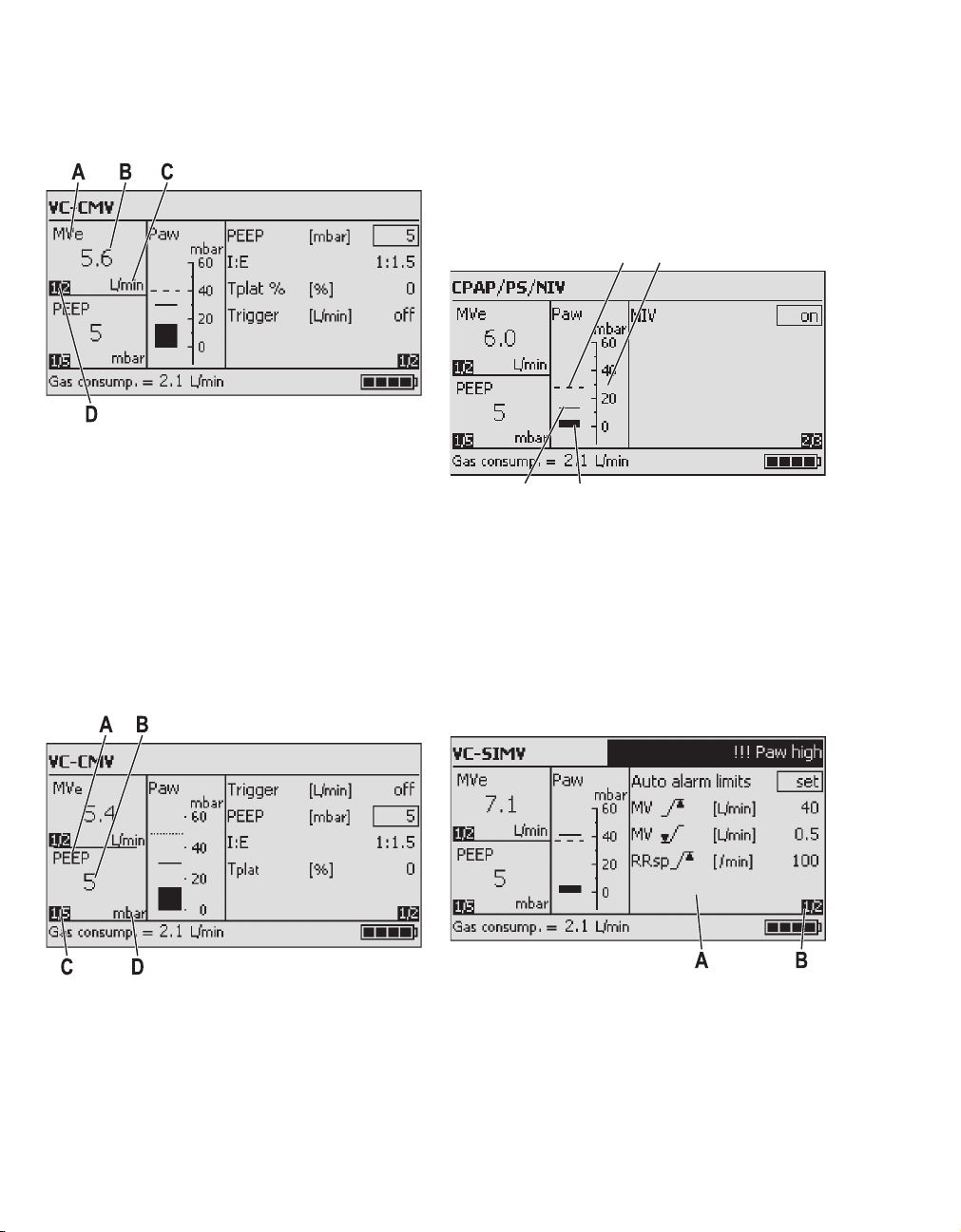
VC-CMV / VC-AC
The following can be set on the display:
Paw
Plateau time
Tplat
Pplat
Pmax
PEEP
t
Tinsp Te
1
Flow
VC-CMV – Volume Controlled - Controlled Mechanical Ventilation.
Volume-controlled ventilation with fixed mandatory
minute volume MV, set with tidal volume VT and
respiratory rate RR.
WARNING
Only use VC-CMV for patients who are not
spontaneously breathing.
Otherwise, the patient may be put at risk by not
receiving sufficient ventilation.
Use VC-AC for patients with partial
spontaneous breathing.
RR
Insp. Flow
– Positive end expiratory pressure PEEP.
– Ventilation time ratio I:E.
– Plateau time Tplat %, in % of the inspiration
t
time.
When setting the ventilation respiratory rate RR,
025
tidal volume VT or ventilation time ratio I:E, the
associated values for inspiration time Ti
inspiration flow are automatically displayed in the
information window.
screen 3
and
Set the ventilation pattern with the controls below
the display:
– Tidal volume VT.
– Ventilation respiratory rate RR.
(minimum possible respiratory rate: 5 per min).
– Maximum airway pressure Pmax.
–O
2 setting, O2 AirMix or 100% O2 FiO2.
48
Instructions for Use Oxylog 2000 plus SW 1.n
Page 49

Operation
Trigger (VC-AC)
NOTE
If in VC-CMV the trigger is set »on«, the ventilation
mode changes into VC-AC.
Refer to the previous section.
VC-AC – Volume Controlled - Assist Control
For synchronisation with the patient's spontaneous
breathing efforts.
The mandatory ventilation strokes are synchronized with the patient's spontaneous breathing
efforts when the trigger is activated and the trigger
sensitivity is set.
The actual respiratory rate may be higher than the
set ventilation respiratory rate RR in this case.
The trigger can be deactivated if synchronisation
with the patient's spontaneous breathing efforts is
not desired.
Successful patient triggering is briefly indicated by
an asterisk (*) in the middle of the status and alarm
message window.
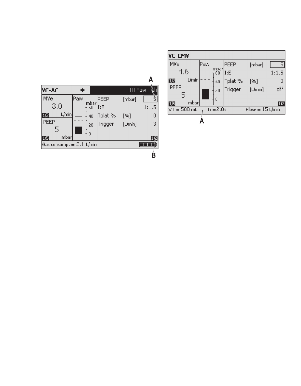
Activating/setting the trigger
Oxylog 2000 plus
A
026
1 Press the key Settings (A) until the trig-
ger parameter is displayed.
2 Select the line Trigger on the display and then
set and confirm the value with the rotary knob.
Small value = high sensitivity.
The ventilation mode VC-AC is shown on the display.
Deactivate trigger
1 Set a value less than 3 L/min or greater than
15 L/min (off is displayed instead of a value).
2 Press the rotary knob to confirm.
The last effective trigger value is adopted by the
ventilator when changing from VC-AC to
SpnCPAP.
For heart-lung resuscitation
During heart-lung resuscitation, the airway pressure Paw is limited to the set Pmax value by the
Oxylog 2000 plus, without ending inspiration
prematurely (pressure-limited, nonconstant-volume ventilation when Pmax is reached).
If Pmax is set to a higher value, a higher minute
volume is possible.
Instructions for Use Oxylog 2000 plus SW 1.n 49
Page 50

Operation
VC-SIMV (optional PS)
The following are set on the display:
Paw
Pmax
PEEP
support PS
rapid
rise time
Pressure
slow
rise time
t
Ti
Flow
1
RR
Insp. Flow
Trigger window
t
Volume Controlled - Synchronized Intermittent
Mandatory Ventilation
For patients with inadequate spontaneous breathing, or for patients who are to be weaned gradually.
Fixed mandatory minute volume MV is set with tidal
volume VT and ventilation respiratory rate RR. The
patient can breathe spontaneously between the
mandatory ventilation strokes and thus contribute
to the total minute volume. Spontaneous breathing
can be assisted with PS.
Set the ventilation pattern with the controls below
the display:
– Tidal volume VT.
– Respiratory Rate RR.
(minimum possible respiratory rate: 2 per min).
– Maximum airway pressure Pmax.
–O
2 setting FiO2.
screen 9screen 10
– Inspiration time Ti.
– Plateau time Tplat %, in % of the inspiration
time.
– Positive end expiratory pressure PEEP.
027
– Sensitivity Trigger.
Successful patient triggering is indicated by an
asterisk (*) in the center of the status and alarm
message window.
When setting the ventilation respiratory rate RR,
tidal volume VT or inspiration time Ti, the associated values for inspiration flow time ratio I:E are
automatically displayed in the information window.
50
Instructions for Use Oxylog 2000 plus SW 1.n
Page 51

Pressure support (optional)
The following can also be set on the display for
VC-SIMV / PS:
– Setting on page 1: Pressure support ∆Psupp
above PEEP.
– Setting on page 2: Pressure rise time Slope
steep slope = short pressure rise time
flat slope = long pressure rise time.
Operation
screen 26
Instructions for Use Oxylog 2000 plus SW 1.n 51
Page 52

Operation
SpnCPAP (optional PS)
Continuous Positive Airway Pressure
WARNING
Only use SpnCPAP for patients with sufficient
spontaneous breathing.
Otherwise there is a risk of the patient
receiving insufficient ventilation.
Spontaneous breathing can optionally be assisted
with PS and NIV.
Set the ventilation pattern with the controls below
the display:
– Maximum airway pressure Pmax.
–O
2 setting FiO2.
Apnea back-up ventilation is only applicable when
using the SpnCPAP mode. In the event of an
apnea, the ventilator will automatically activate
volume-controlled mandatory ventilation
(VC-CMV).
When an apnea occurs, the device simultaneously
issues an alarm signal and switches to volume controlled ventilation with the parameters respiratory
rate RRapn, tidal volume VTapn, and the maximum airway pressure Pmax when the apnea time
Tapn has been reached. The ventilation time ratio
I:E is set to 1:1.5. The plateau time Tplat % is 0.
The patient can breathe spontaneously during
apnea ventilation. The mandatory frequency
RRapn remains constant.
Setting apnea ventilation
Apnea ventilation
Paw
Pmax
Apnea alarm time
Tapn
Flow
52
Start
apnea ventilation
with apnea alarm
RR
Oxylog 2000 plus
A
t
1
On the display:
1 Press the Settings key (A) until
page appears.
t
2/3
2 Set Tapn with the rotary knob (B) to a value
between 15 and 60 seconds.
029US
Instructions for Use Oxylog 2000 plus SW 1.n
BC
030
Page 53

Operation
The parameters RRapn and VTapn, which are
required for setting apnea ventilation, are now
displayed:
3 Set RRapn and VTapn.
4 Set Pmax. This determines the maximum air-
way pressure allowed during apnea ventilation.
The ventilation time ratio I:E = 1:1.5 and the plateau
time Tplat % = 0 are preset during apnea
ventilation.
To switch apnea ventilation OFF
z Set Tapn to OFF.
Pressure support (optional)
The following can additionally be set on the display
for SpnCPAP / PS:
screen 13
– Sensitivity Trigger (for synchronization with the
patient's spontaneous breathing efforts).
Successful patient triggering is briefly indicated
by an asterisk (*) in the middle of the status
alarm messages window.
– Pressure support ∆Psupp above PEEP.
– Pressure rise time Slope (for pressure
support ∆Psupp).
screen 12
To end apnea ventilation
z Press the Alarm Reset key.
The ventilator resumes ventilating with the original
mode and parameter settings.
The manufacturer default settings are:
– RRapn = 12 /min
–VTapn
=500mL
These default settings can be configured.
Refer to the "Customer Service Mode" section for
additional information.
NOTE
Apnea ventilation can only be activated in
the ventilation mode SpnCPAP without NIV.
The minimum ventilation required by the patient
must be monitored via the lower alarm limit
MV .
Instructions for Use Oxylog 2000 plus SW 1.n 53
Page 54

Operation
NIV – Non-invasive ventilation
Mask ventilation (optional)
NIV can only be activated as a supplementary
function in the pressure-controlled ventilation
modes SpnCPAP and SpnCPAP / PS. Mask leakages are detected by the device, compensated and
included in the measured values for VTe and MVe.
WARNING
If NIV is not activated, measured values for VTe
and MVe will be inconsistent if there are
leakages during ventilation.
Use of NIV
WARNING
Dead space increases when using masks.
Note the mask manufacturer's instructions!
WARNING
Application mode NIV may not be activated
with intubated patients!
Risk of undetected leaks and inadequate ventilation!
WARNING
Check MV alarm limits after deactivating NIV
mode!
– The supplement NIV appears in the upper
section of the display.
screen 14
Oxylog 2000 plus automatically adjusts to the
requirements of mask ventilation. Leakage flows
are compensated automatically and the leakage
alarm is inactive.
WARNI NG
Set the lower alarm limit MV according to
the minimum ventilation required for the
patient.
Otherwise, there is a risk of the patient
receiving insufficient ventilation.
Apnea ventilation is not permitted by the ventilator
when NIV is active.
WARNING
Avoid high airway pressure.
Risk of aspiration!
To switch on NIV
1 Press the Settings key until display page
appears.
2/3
2 Activate the line NIV off.
3 Select NIV on and confirm.
54
Instructions for Use Oxylog 2000 plus SW 1.n
Page 55

O2 AirMix or 100% O2
The FiO2 concentration can be set to O2 AirMix or
100% O2, regardless of the ventilation mode.
When set to O
Oxylog 2000 plus will draw in ambient air, to realize
2 concentration of approximately 40%.
an FiO
However, the O
realized depends on the mean airway pressure and
the inspiratory flow. The O2 concentration can
never be lower than 40%. This is shown in the following graphics:
(%)
O2
40
20
0
3
2 concentration which can be realized at a Pmean
O
of 5 mbar.
(%)
O2
40
20
0
10
2 concentration which can be realized at a Pmean
O
of 15 mbar.
2 AirMix the injector principle of the
2 concentration, which can be
80 (%)
Flow
(L/min.)
40
O2 = f(Flow, Paw)
100
82 (%)
Flow
(L/min.)
35
O2 = f(Flow, Paw)
100
Operation
(%)
O2
85 (%)
40
20
0
15
30
O
2 concentration which can be realized at a Pmean
O2 = f(Flow, Paw)
100
Flow
(L/min.)
of 30 mbar.
(%)
O2
93 (%)
031032
40
20
0
20
O2 = f(Flow, Paw)
2 concentration which can be realized at a Pmean
O
100
Flow
(L/min.)
of 60 mbar.
The O2 concentration is a calculated value. It is not
measured by an internal O
When the O
2 concentration has been set, the value
2 sensor.
will be displayed after approximately 30 seconds.
WARNING
In toxic surroundings:
– The patient must be ventilated with 100%
2 so that toxic constituents do not enter
O
into the breathing gas.
– The patient must be immediately trans-
ferred to a breathable atmosphere in order
to prevent inhalation of toxic air when
spontaneous breathing resumes.
033031
Instructions for Use Oxylog 2000 plus SW 1.n 55
Page 56

Operation
Calibration
The pressure and flow sensors are automatically
calibrated by the device at regular intervals without
interrupting ventilation.
Screen brightness
The screen brightness levels can be set on the last
page of the Settings menu, from level 1/4 to 4/4:
– The setting Brightness is active in both
mains and battery operation when adjusting the
settings on the ventilator.
Volume loudness
The volume loudness level can be set on the last
page of the Alarms menu, from level 1/4 to 4/4.
The saved calibration values are retained even
when the device is switched OFF.
– The setting Brightness is active during
battery operation, when no controls have been
set for a period longer than one minute.
56
Instructions for Use Oxylog 2000 plus SW 1.n
Page 57

Shutdown
– After disconnecting the patient
Switch the ventilator OFF:
Operation
Oxylog 2000 plus
B
1 Press the key
3 seconds. The yellow lamp flashes and
ventilation is terminated by the device.
2 Press the rotary knob (B) to acknowledge the
alarm !!! Confirm device OFF with rotary
knob.
When O
3 Close the cylinder valve.
When medical gas is supplied from the pipeline
system:
4 Disconnect the high pressure connection from
2 is supplied from a cylinder:
WARNING
The cylinder valve must be closed completely
to avoid gas flow leakage by the device.
the source.
O (A) for approximately
A
035
Instructions for Use Oxylog 2000 plus SW 1.n 57
Page 58

This page intentionally left blank
58 Instructions for Use Oxylog 2000 plus SW 1.n
Page 59

Alarms
Types of alarms . . . . . . . . . . . . . . . . . . . . . . 60
In the event of an alarm . . . . . . . . . . . . . . . . 61
Setting alarm limits . . . . . . . . . . . . . . . . . . . 63
Alarms
Instructions for Use Oxylog 2000 plus SW 1.n 59
Page 60

Alarms
Types of alarms
The actual screen display may differ in appearance
or configuration.
Oxylog 2000 plus assigns a priority to the alarm
message. This message highlights the text with the
appropriate number of exclamation marks and
generates different tone sequences for the respective alarms.
!!! = Warning
!! = Caution
! = Advisory
Refer to the list "Alarm – Cause – Remedy" on
page 79 for information on how to remedy the
faults.
Oxylog 2000 plus
A
B
Caution
An alarm of medium priority.
z The alarm LED (A) flashes yellow.
Caution messages are highlighted by two exclamation marks.
Example: !! No int. battery ?
Oxylog 2000 plus generates a three-tone
sequence, which is repeated approximately every
20 seconds.
Advisory
An alarm of low priority.
z The yellow alarm LED (A) lights up.
Advisory messages are identified by one exclamation mark.
Example:
! Settings not confirmed
Low-priority alarm.
The Oxylog 2000 plus generates a two-tone alarm
sequence, which sounds only once.
Warning
An alarm with high priority
z The alarm LED (A) flashes in red.
Warnings are highlighted by three exclamation
marks and displayed in inverted form (B).
Example:
!!! Apnea
The Oxylog 2000 plus generates a sequence of five
tones, which sound twice and are repeated approximately every 7 seconds.
60
036
Instructions for Use Oxylog 2000 plus SW 1.n
Page 61

In the event of an alarm
Alarms
Oxylog 2000 plus
C
A
B
z The LED (A) flashes red or yellow.
Or
z The alarm message appears on the right of the
status and alarm message window (C).
When the fault has been remedied the alarm tone
is cancelled.
Alarms which have been remedied remain on the
display and can be acknowledged (reset):
1 Press the Alarm Reset key (B).
The alarm message is removed from the
display.
Every alarm which has been remedied, but not
acknowledged, will be overwritten by a new alarm
or advisory message.
Suppress alarm tones
WARNING
Check the display regularly for alarm mes-
sages when the alarm tones are silenced.
Otherwise, alarms can be missed.
Oxylog 2000 plus
A
037
1 Press the key (A).
The yellow LED lights up and all alarm tones are
suppressed for approximately 2 minutes.
Alarm tones are resumed by the device after
these 2 minutes.
CAUTION
To be notified of new audible alarms, the
2 minutes alarm silence must be reset.
NOTE
The loudness of alarm tones can be adjusted.
Refer to section "Volume loudness" on page 56.
If alarm tones are to be heard again before the
2 minutes have expired:
2 Press the key (A) again and its LED goes
out.
038
NOTE
Alarm tones are suppressed for a maximum of
2 minutes.
Instructions for Use Oxylog 2000 plus SW 1.n 61
Page 62

Alarms
In the event of a gas failure
CAUTION
In the event of a gas failure, the Oxylog 2000 plus
cannot continue ventilation and issues the alarm
!! Supply pressure low.
Immediately start ventilating the patient with an
independent manual ventilation device (resuscitation bag) using PEEP and/or increased inspiratory
oxygen concentration where appropriate.
In the event of an internal power failure
WARNING
In the event of an internal power failure, auto-
matic ventilation, volume measurement and
alarms do not operate!
An audible alarm goes off to indicate the internal power failure.
Spontaneous breathing can continue through
the emergency air intake.
Immediately start ventilating the patient with
an independent manual ventilation device
(resuscitation bag) using PEEP and/or
increased inspiratory oxygen concentration
where appropriate.
62
Instructions for Use Oxylog 2000 plus SW 1.n
Page 63

Setting alarm limits
Alarms
CAUTION
Set alarm values carefully.
Extreme alarm values can render the alarm
system useless.
Upper alarm limit for Paw Pressure limitation with Pmax
Regardless of the set ventilation mode, the airway
pressure is controlled by the ventilator and limited
to the set maximum inspiratory pressure Pmax.
Pmax appears in the pressure bar graph as a
dashed line.
When this dashed line is reached, Oxylog 2000
plus issues a !!! Paw high alarm. The volume-con-
trolled stroke is terminated (ventilation with nonconstant volume).
Oxylog 2000 plus
A
To set alarm limits for MV and RRsp
2 Press the key Alarms (A).
Display example Alarms screen with variable
alarm limits.
= lower alarm limit.
= upper alarm limit.
Alarm Range
MV 2 to 41 L/min
MV 0.5 to 40 L/min
RRsp 10 to 100 /min
Example: Setting the upper alarm limit for MV.
1 Select and activate the line MV on the dis-
play.
2 Set and confirm the value.
WARNING
Set the lower alarm limit MV according to
the minimum ventilation required for the
patient.
Otherwise, there is a risk of the patient
receiving insufficient ventilation.
B
039
1 Set the maximum airway pressure Pmax via the
Pmax control (B).
The airway pressure is limited when Pmax is rea-
ched; inspiration will not be terminated prematurely.
Lower alarm limit for Paw
A lower alarm limit need not be set for the airway
pressure Paw.
generates an alarm when it no longer detects a
pressure difference of more than 5 mbar between
inspiratory and expiratory pressure.
Instructions for Use Oxylog 2000 plus SW 1.n 63
Oxylog 2000 plus automatically
Page 64

Alarms
Setting alarm limits automatically
WARNING
After using the function Auto alarm limits:
check if the new alarm limits are appropriate
for the patient.
Risk of hypoventilation.
The function Auto alarm limits sets the alarm
limits on the basis of the following actual measured
values at the time of activation:
MV : Measured value MV +2 L/min
MV : Measured value MV –2 L/min
RRsp : Measured value RRsp +5/min, with a
minimum of 10/min.
This automatic selection of alarm limits is performed only once, when confirmed, via the rotary
knob. The alarm limits refer to the current measured values for MV and RRsp.
64
Instructions for Use Oxylog 2000 plus SW 1.n
Page 65

Monitoring
Displaying the airway pressure. . . . . . . . . . 66
Displaying MVe and VTe . . . . . . . . . . . . . . . 66
Displaying O2 values . . . . . . . . . . . . . . . . . . 66
Displaying other measured values . . . . . . . 67
Monitoring
Instructions for Use Oxylog 2000 plus SW 1.n 65
Page 66

Monitoring
Displaying the airway pressure
The actual screen display may differ in appearance
or configuration.
The airway pressure is displayed in a bar graph
indicator on the display.
Refer to the "Operating concept" section on
page 24 for additional information.
Displaying MVe and VTe
MVe and VTe are displayed in the measured MVe /
VTe window.
Refer to the "Operating concept" section on
page 24 for additional information.
Displaying O2 values
The O2 concentration can be displayed in the measured values window.
NOTE
This value is a calculated value, based on the
measured air intake and total flow. It is not based
on a measurement by an O
When the O
changed, the calculated value will be updated after
approximately 30 seconds.
Refer to "Values window" on page 24 for additional
information.
2 AirMix – 100% O2 switch has been
2 sensor!
To switch between the values:
z Press the upper Values key: the next
value is displayed on the screen.
66
Instructions for Use Oxylog 2000 plus SW 1.n
Page 67

Displaying other measured values
Additional measured values are displayed in the
measured values window.
Refer to the "Operating concept" section on
page 24 for additional information.
To switch between the values:
z Press the lower Values key: the next
value is displayed on the screen.
In the values window five different values can be
displayed.
These five values can be selected out of eight
measured values options, in any desired order.
Refer to "Abbreviations" on page 16. These options
are:
–O
2
–RR
–RRsp
– PEEP
–Pmean
–PIP
–Pplat
–MVe
spon
Monitoring
The five values displayed in the measured values
window can be configured in the customer service
mode. Refer to the "Set the measured values display window" on page 75 for additional information.
Instructions for Use Oxylog 2000 plus SW 1.n 67
Page 68

This page intentionally left blank
68 Instructions for Use Oxylog 2000 plus SW 1.n
Page 69

Configuration
Set configuration parameters / display informa-
tion. . . . . . . . . . . . . . . . . . . . . . . . . . . . . . . . . 70
Displaying configuration and information . 71
Set language . . . . . . . . . . . . . . . . . . . . . . . . . 71
Display the battery type . . . . . . . . . . . . . . . . . 71
Customer Service Mode. . . . . . . . . . . . . . . . 72
To enter customer service mode . . . . . . . . . . 73
Set startup settings. . . . . . . . . . . . . . . . . . . . . 74
Exit customer service mode . . . . . . . . . . . . . . 78
Configuration
Instructions for Use Oxylog 2000 plus SW 1.n 69
Page 70

Configuration
Set configuration parameters / display information
The actual screen display may differ in appearance
or configuration.
1 Switch the Oxylog 2000 plus ON. Press the
key.
The device performs a self-test and the
operator is prompted to enter the configuration
menu or device check:
Press rotary knob for device check and configuration.
2 Press the rotary knob and confirm.
The main menu is then displayed:
Select and confirm Configuration and informa-
tion.
O
screen 15
70
Instructions for Use Oxylog 2000 plus SW 1.n
Page 71

Displaying configuration and information
Configuration
– The settings made via the "Configuration" are
retained after the ventilator is switched OFF.
– Configuration can be cancelled by pressing the
Alarm reset key or by startup of ventilation.
The following settings can be made for the application concerned via Configuration and informa-
tion:
– Language
The following ventilator data can be displayed via
Configuration and information:
– Identification No. (Device-ID)
– Total hours of operation (Working hours)
– Hours of operation since the last inspection and
maintenance (Hours since service time)
– Battery type and battery capacity.
3 Select the language and confirm.
The new language selected is effective
immediately.
Display the battery type
z Press the key Settings to select the
menu Configuration and information .
The performance data of the inserted battery
are displayed on the device.
2/2
screen 16screen 17
screen 16
3 Select and confirm Configuration and infor-
mation.
Set language
1 Press the key Settings to select the
menu Configuration and information .
2 Select and activate the line Language.
Instructions for Use Oxylog 2000 plus SW 1.n 71
1/2
Page 72

Configuration
Customer Service Mode
WARNING
Ventilation is not possible in customer service
mode.
In customer service mode, the ventilator performs
function tests, outputs status information and
permits configuration of parameter settings.
Displays in customer service mode appear in English and cannot be changed to any other language.
001 Set startup settings. Configure start-up settings, restore manufacturer's
default settings.
002 Select hose type. Determine which ventilation hose system is used
(reusable or disposable hose system).
003 Set date and time
(Greenwich Mean Time GMT).
004 Set measured values display window. Configure the layout of measured values in the measured
005 Enter activation code. Enter the activation code for options.
006 Test buttons and potentiometer. Check for correct functioning of keys and controls.
007 Test loudspeaker, buzzer, LEDs and
display.
008 Display accu and supply data. Display battery data and condition of the supply voltage.
009 Display actual technical errors. Display any active technical errors.
010 Display error and info logbook. Calibration logbook and technical errors in chronological
011 Display settings logbook. Logbook of operating phases and ventilator settings.
012 Display language text. Display screen texts in two selectable languages.
Set date and time.
values window or restore manufacturer's default settings.
Check for correct functioning of loudspeaker, buzzer,
LEDs and display.
order.
72
Instructions for Use Oxylog 2000 plus SW 1.n
Page 73

Configuration
To enter customer service mode
Oxylog 2000 plus
A
B
CD
E
1 Turn controls (C) and (D) VT and RR all the way
to the right.
2 Switch ON (E) the device (briefly press
and simultaneously press and hold the Values
key (A) and the Values key (B) until
the main Customer Service Mode menu
appears.
3 Set the number of the required test in the main
menu with the central rotary knob.
O key)
Settings in customer service mode
1 Select the required function with the cursor
(asterisk).
– To select the parameter: turn the rotary
knob.
– To activate the parameter: press the rotary
knob.
– To set the value: turn the rotary knob.
– To confirm the value: press the rotary knob.
To exit the parameter settings menu
04011737170.tiff
screen 19
1 Select the line EXIT.
2 Press the rotary knob and confirm.
The set values are saved and remain effective
whenever ventilation is started after switching
ON.
4 Activate test = press rotary knob.
Instructions for Use Oxylog 2000 plus SW 1.n 73
Page 74

Configuration
Set startup settings
Range of the settings:
Parameter Range
Trigger 0 (OFF) 3 to 15 L/min
PEEP 0 to 20 mbar
I:E 3:1 to 1:4
Ti 0.2 to 10.0 s
Tplat % 0 to 50%
∆Psupp 0 to 35 mbar
Slope SLOW, STANDARD, FAST
NIV ON, OFF
Tapn 0 (OFF), 15 to 60 s
VTapn 50 to 2000 mL
RRapn 12 to 60 bpm
MV-high 2.0 to 41 L/min
MV-low 0.5 to 40 L/min
RR 10 to 100 bpm
Loudness 1/4 to 4/4
Brightness 1/4 to 4/4
The default settings for the parameters are displayed on the screen when the ventilator is
switched ON. The settings can be adjusted.
Advance to the second page:
1 Select the line Page, confirm and turn rotary
knob.
screen 21screen 24
To restore the manufacturer's defaults:
2 Select and confirm line Set factory default.
Select hose type
74
The type of ventilation hose (reusable or
disposable hose system) can be configured.
The gas output sockets for the flow measuring
hoses must correspond to the hose type system
screen 20
selected.
Instructions for Use Oxylog 2000 plus SW 1.n
Page 75

Set date and time
The date and time can be set.
1 Set the current date and time with the positions
Year, Month, Day, Hour and Minute and confirm.
2 The date and time can be confirmed with »Set«.
Set the measured values display window
In the measured values window five different
values can be displayed.
Configuration
NOTE
It is recommended that you have the O2 value as
a displayed value.
To define the five values to be displayed:
z Start configuration on page 1/5 and continue
through to 5/5.
Enter activation code
10237170s creen 32
These five values can be selected out of a total of
eight measured values, in any desired order.
These are:
–O
2
–RR
–RRsp
– PEEP
–Pmean
–PIP
–Pplat
–MVe
spon
The activation codes for options can be entered.
The activated options are then displayed.
Test buttons and potentiometer
screen 25
The operating elements on the front panel are displayed schematically on the screen.
– Display = screen
– B = buttons
Instructions for Use Oxylog 2000 plus SW 1.n 75
Page 76

Configuration
Set the controls accordingly for the test:
– VT to 500 mL
– RR to 20 /min
– Pmax to 40 mbar
– FiO
2 to O2 AirMix
These settings are displayed on the screen.
To test the buttons:
1 Briefly press the corresponding button.
The associated letter on the screen changes
from "B" to "X". If the button has an LED, it will
be illuminated by the device. If there are buttons
without LED, the yellow warning LED will light
up on the device.
2 Briefly press the O key.
The ventilator switches OFF if it is pressed for
longer than 3 seconds.
The function of the rotary knob is not included in the
test.
The selected test remains active until the rotary
knob is pressed again.
Display accu (battery) and supply data
The parameters of the replaceable battery and the
status of the external power supply are displayed.
Display (example):
fd
1 Advance to the second page:
2 Select the line Page, confirm and turn rotary
knob.
Display (example):
Test loudspeaker, buzzer, LEDs and display
To test the loudspeaker, buzzer, all LEDs and the
display:
1 Select the required test
2 Start the test. Each function is tested by the
device.
To test the screen display (Test display):
3 Turn the rotary knob; various test cards are dis-
played.
76
Instructions for Use Oxylog 2000 plus SW 1.n
Page 77

Configuration
Display actual technical error
Momentarily active technical errors are displayed
with the error number and a brief description.
Display (example):
Display error and info logbook
Any technical errors and/or special occurrences,
such as activation of a software option, completion
of the device check and device calibration, are
listed in chronological order.
Display (example):
Display settings logbook
screen 2410137170
The operating phases with ventilator settings and
time are listed in chronological order.
Advance to the next page:
z Select line Page, confirm and turn the rotary
knob.
Display language text
Alarm messages and advisory messages are
Advance to the next page:
displayed by the ventilator in the selected display
languages – one text per page.
z Select line Page, confirm and turn the rotary
knob.
Advance to the next page:
1 Select line Page, confirm and turn the rotary
knob.
Choose another language:
2 Select line Language 1 or Language 2, confirm
and turn the rotary knob.
Instructions for Use Oxylog 2000 plus SW 1.n 77
Page 78

Configuration
Exit customer service mode
1 Press the key O for approximately
3 seconds; the LED flashes yellow.
To switch ventilation ON:
2 Briefly press the key O.
To switch OFF:
3 Press the rotary knob.
78
Instructions for Use Oxylog 2000 plus SW 1.n
Page 79

Problem Solving
Alarm - Cause - Remedy . . . . . . . . . . . . . . . 80
Messages in the information window. . . . . 84
Error messages during the device check . 85
Problem Solving
Instructions for Use Oxylog 2000 plus SW 1.n 79
Page 80

Problem Solving
Alarm - Cause - Remedy
Oxylog 2000 plus classifies alarm messages
according to three priority levels and identifies
these accordingly with the aid of exclamation
marks:
Warning !!! High priority alarm message
Caution !! Medium priority alarm
message
Advisory ! Low priority alarm message
In the following table, the alarm messages are
listed in alphabetical order. If an alarm occurs, the
table helps to identify causes and remedies. The
different causes and remedies should be worked
through in the order listed until the cause of the
alarm has been resolved.
When multiple alarms occur, they are displayed
according to their Alarm Rank, as illustrated in the
table below. A lower number has a higher rank.
Messages in the alarm window
Alarm Cause Remedy Alarm
!!! Apnea Spontaneous breathing by
the patient has failed, or disconnection.
Faulty flow sensor. Replace flow sensor.
!!! Apnea ventila-
tion (only for
SpnCPAP)
!! Charge int. bat-
tery
!! Check settings
flow
The ventilator has automatically switched over to mandatory ventilation after
detecting an apnea (only in
SpnCPAP mode).
Oxylog 2000 plus draws its
power from the internal battery due to the absence of
an external DC supply. Only
a few minutes of operating
time remain (approximately
10 minutes).
The flow resulting from the
settings for "Tidal volume
VT per unit time" is not possible.
Ventilate in VC-CMV mode.
Ensure that hose connections are
tight.
Check ventilation mode. Return to
original ventilation mode: Press
the Alarm Reset key.
The ventilator must immediately
be reconnected to the mains supply, an onboard DC supply or a
fully charged battery.
Change tidal volume VT or inspiratory time Ti or ventilation time ratio
I:E.
Rank
6
5
16
14
80
Instructions for Use Oxylog 2000 plus SW 1.n
Page 81

Problem Solving
Alarm Cause Remedy Alarm
!! Check settings
time
!!! Confirm device
OFF with rotary
knob
!!! Device failure Technical defect. Contact your local DrägerService
!! Flow measure-
ment inop
!! Gas delivery fail-
ure
!! High respiratory
rate
!! Int. battery
charging inop
!!! Int. battery dis-
charged
!! Int. battery in use Oxylog 2000 plus draws its
!! Key failed Technical defect. Contact your local DrägerService
The expiration time resulting from the settings for RR
and I:E or Ti is not possible.
Key
O has been pressed
for 3 seconds.
Change RR or I:E or Ti.13
To switch OFF: confirm.
To continue ventilation, press key
O again.
for additional support.
Measurement hoses for
flow measurement hoses
kinked, disconnected or
leaking.
Flow sensor defective. Replace flow sensor.
Technical defect. Contact your local DrägerService
Technical defect. Contact your local DrägerService
Patient breathes at a high
spontaneous rate.
Technical defect. Contact your local DrägerService
The operating time for operation with the internal battery has expired and an
external DC supply has not
been connected.
power from the internal battery due to the absence of
an external DC supply.
Ensure flow measurement hoses
are connected correctly.
for additional support – restricted
operation is now possible.
for additional support – restricted
operation is now possible.
Check patient's condition, check
ventilation pattern, correct alarm
limit RRsp if necessary.
for additional support – restricted
operation is now possible.
The ventilator must immediately
be reconnected to a mains supply,
an on-board DC supply or a fully
charged battery.
Press the Alarm Reset key to
confirm the alarm.
for additional support – restricted
operation is now possible.
Rank
---
1
23
20
15
17
2
12
19
Instructions for Use Oxylog 2000 plus SW 1.n 81
Page 82

Problem Solving
Alarm Cause Remedy Alarm
!!! Leakage
(not in NIV)
The measured expiratory
tidal volume VTe is approximately 40% lower than the
inspiratory value.
Repair leaks in hose system and
possibly in the tube. Check placement of lower sentence.
Use new flow measuring hoses.
Faulty flow sensor. Replace flow sensor.
The ventilator may not function properly.
Contact your local DrägerService
for additional support.
!! Loss of data Technical defect. Contact your local DrägerService
for additional support – restricted
operation is now possible.
!! Loudspeaker
inop
Technical defect. Contact your local DrägerService
for additional support – restricted
operation is now possible.
!!! MV high The upper alarm limit for the
minute volume MV has
been exceeded.
Check patient's condition, check
ventilation pattern, adjust alarm
limits if necessary.
Faulty flow sensor. Replace flow sensor.
The ventilator may not function properly.
!!! MV low The minute volume MV has
dropped below its lower
alarm limit.
Contact your local DrägerService
for additional support.
Check patient's condition, check
ventilation pattern, adjust alarm
limits if necessary.
Leak in exhalation system. Ensure connections in exhalation
system are tight.
Faulty flow sensor. Replace flow sensor.
The ventilator may not function properly.
!! No int. battery ? Internal battery not
installed, faulty or wrong
Contact your local DrägerService
for additional support.
Fit battery or confirm alarm or
change internal battery.
battery installed.
! No int. battery ? Internal battery not
installed, faulty or wrong
battery installed.
! No int. battery
charging
Internal battery cannot be
charged.
Advisory message, is displayed
continuously when confirmed.
Change internal battery.
Press the Alarm Reset key to
confirm the alarm. Change internal battery.
Rank
9
21
22
8
7
24
25
26
82
Instructions for Use Oxylog 2000 plus SW 1.n
Page 83

Problem Solving
Alarm Cause Remedy Alarm
!!! Paw high The alarm limit Pmax for the
airway pressure has been
reached. Patient "fights" the
Check patient's condition, check
ventilation pattern, adjust alarm
limits if necessary.
ventilator, coughing.
Ventilation hose kinked, or
obstructed.
!!! Paw low No pressure difference >5
Check hose system, breathing
valve and tube.
Inflate cuff and check for leaks. 4
mbar between inspiration
and expiration or set pressure level is not achieved.
Leak in cuff.
Leakage or disconnection. Check hose system for leaking
connections. Ensure that the
breathing valve has been installed
correctly.
!! Paw measure-
ment inop
Fault in flow measurement
hoses.
Ensure hose system for loose con-
nections. Ensure flow measure-
ment hoses are connected
correctly.
Technical defect. Contact your local DrägerService
for additional support – restricted
operation is now possible.
! Self test OK The device has been
switched on and the selftest completed successfully.
!! Set correct FiO
2 The control knob for setting
2 AirMix or 100% O2 is set
O
The message can be confirmed or
it will be cancelled automatically
with the next message.
Set the Control knob in the right or
left position.
in a middle position.
! Settings not con-
firmed
Parameters have been
changed on the screen but
Press the rotary knob to confirm
the parameter changes.
not confirmed.
!! Supply pressure
low
Supply pressure <270 kPa. Ensure that supply pressure
exceeds 270 kPa.
Rank
3
18
28
10
27
11
Instructions for Use Oxylog 2000 plus SW 1.n 83
Page 84

Problem Solving
Messages in the information window
(Numerical examples)
Message Cause Explanation/Remedy
RR = 12 per min or
VT = 800 mL
I : E = 1 : 1.5
Flow = 15 L/min
RR = 12 per min or
VT = 800 mL
Ti = 0.7 s
Flow = 35 L/min
I : E = 1 : 1.5
Ti = 2 s
Confirm PEEP above 10 mbar ?
Gas consumption = 10 L/min Standard display in information
(Battery capacity)
Psupp = 22 mbar Change in ∆Psupp or PEEP. Psupp
Change in Ti, RR or VT in ventilation mode VC-SIMV.
Change in I/E, RR or VT in ventilation mode VC-CMV, VC-AC.
Change in Ti.
PEEP >10 mbar has been set but
not confirmed.
window for the current gas
consumption.
Standard display in information
window for the current battery
capacity.
The required setting of
PEEP >10 mbar is only possible
when confirmed via the rotary
knob.
is the absolute pressure
resulting from PEEP + ∆Psupp.
84
Instructions for Use Oxylog 2000 plus SW 1.n
Page 85

Problem Solving
Error messages during the device check
Message Cause Explanation/Remedy
No communication control- /
charge-board
System leakage Leak in ventilation hose system
No test lung Test lung not connected or mayor
Breathing valve inop PEEP >10 mbar has been set but
Pressure measurement inop The ventilation hose system has
PEEP-valve inop Internal leak in system Check hoses, breathing valve,
Patient flow measurement
inop
Device defective Contact your local DrägerService
for additional support.
Check hoses, breathing valve,
and/or test lung.
leakage
not confirmed.
not been connected correctly.
Pressure measurement is not possible.
Device defective Contact your local DrägerService
Flow measurement implausible Replace flow sensor.
flow sensor and test lung for leaks
and replace if necessary.
Connect test lung.
Check hoses, breathing valve,
flow sensor and test lung for leaks
and replace if necessary.
The required setting of
PEEP >10 mbar is only possible
when confirmed via the rotary
knob.
Connect ventilation system correctly.
Contact your local DrägerService
for additional support.
flow sensor and test lung for leaks
and replace if necessary.
for additional support.
Contact your local DrägerService
for additional support.
Instructions for Use Oxylog 2000 plus SW 1.n 85
Page 86

This page intentionally left blank
86 Instructions for Use Oxylog 2000 plus SW 1.n
Page 87

Cleaning, Disinfection and Sterilization
Disassembly . . . . . . . . . . . . . . . . . . . . . . . . . 88
Disassemble the reusable hose system . . . . . 88
Remove the disposable hose system. . . . . . . 90
Reprocessing procedure . . . . . . . . . . . . . . . 91
Cleaning and disinfecting . . . . . . . . . . . . . . . . 91
Sterilizing the reusable hose system . . . . . . . 92
After care . . . . . . . . . . . . . . . . . . . . . . . . . . . . 93
Note service life of the hose system. . . . . . . . 93
Cleaning, Disinfection and Sterilization
Instructions for Use Oxylog 2000 plus SW 1.n 87
Page 88

Cleaning, Disinfection and Sterilization
Disassembly
Disassemble the reusable hose system
B
A
C
A
B
011
1 Disconnect the ventilation hose (A) from the gas
output.
2 Disconnect the flow measuring hoses (B) from
the nozzles.
3 Disconnect the medical gas hose (C) from the
Oxylog 2000 plus.
WARNI NG
When disconnecting the ventilation hose,
always grip the sleeve (A) and not the corrugations (B)!
If this is not done, the corrugations or hose
may be torn from the sleeve.
011
88
Instructions for Use Oxylog 2000 plus SW 1.n
Page 89

Cleaning, Disinfection and Sterilization
Breathing valve, disassembly
D
A
B
B
C
4 Disconnect the flow sensor (A) from the breath-
ing valve.
WARNING
Do not twist or use force when disconnecting
the flow measuring hoses from the flow sensor nozzles. This can damage the flow sensor.
5 Carefully detach the flow measuring hoses (B)
from the flow sensor.
Pull in the axial direction of the hose nozzles.
6 Detach the angled connector (C) from the flow
sensor.
WARNING
Do not allow any objects to enter the flow sensor to prevent risk of malfunctions.
Do not purge with compressed air. The wind
vane inside may be damaged and cause measuring errors!
A
B
011
o
8 Turn the cover (A) about 90
counterclockwise to unlock the cover.
9 Remove the silicone diaphragm (B).
WARNING
Do not disassemble breathing valve any further.
Do not allow any objects to enter the housing
of the breathing valve to prevent risk of malfunctions!
Do not damage the silicone diaphragm and
other parts.
011
7 Detach the ventilation hose (D) from the brea-
thing valve.
Instructions for Use Oxylog 2000 plus SW 1.n 89
A
011
Page 90

Cleaning, Disinfection and Sterilization
WARNING
The rubber disc (A) in the housing must not be
removed, damaged or bent, otherwise the
valve will not work properly and endangers
the patient.
Risk of CO2 rebreathing.
Remove the disposable hose system
A
B
C
1 Disconnect flow measuring hoses (A and B).
2 Disconnect the ventilation hose (C).
3 Correctly dispose of the complete disposable
hose system. Refer to the chapter "Disposal"
on page 99.
CAUTION
The disposable hose system must not be
sterilized: it cannot withstand high temperatures
and may be damaged!
90
047
Instructions for Use Oxylog 2000 plus SW 1.n
Page 91

Reprocessing procedure
– Clean breathing valve, flow sensor, angled
adapter and ventilation hoses of the reusable
hose system after use.
– Always exchange the disposable hose system
after use on a patient.
– The disposable hose system must always be
disposed of correctly. Refer to the chapter "Disposal" on page 99.
– Clean the ventilator and medical gas hoses with
a disposable cloth if heavily soiled.
– Replace the disposable hose system in case of
contamination by e.g. vomitus or coughing.
– Clean the reusable hose system in case of con-
tamination by e.g. vomitus or coughing.
WARNING
Always follow hospital/EMS procedures for
handling equipment contaminated with body
fluids.
WARNING
Always follow local regulations governing the
disposal of infectious waste and materials
contaminated with body fluids to prevent the
risk of infection.
Cleaning and disinfecting
To ensure material compatibility, use disinfectants
based on:
– aldehydes
– alcohols
– quaternary ammonia compounds.
Cleaning, Disinfection and Sterilization
CAUTION
Disinfectants based on:
– compounds containing alkylamine
– compounds containing phenol
– compounds releasing halogen
– strong organic acids
– compounds releasing oxygen
may cause damage, which is not always immediately apparent, to materials, particularly those
used for the breathing valve, flow sensor and
angled connector.
CAUTION
Sterilization of the ventilator itself with ethylene
oxide (EtO) is not recommended.
WARNING
Always follow accepted hospital/EMS proce-
dures for disinfecting equipment contaminated with body fluids (protective clothing,
eyewear, etc.).
Users in the Federal Republic of Germany are
recommended to use only disinfectants on the current DGHM list (DGHM: German Society for Hygiene and Microbiology).
The following disinfectants on the DGHM list are
recommended:
– Dismozon pur
–Incidur
– Sekusept Powder
– Trichlorol
The DGHM list (published by: mhp-Verlag, Wiesbaden) also specifies the active ingredient in each disinfectant. Disinfectants based on the active
ingredients aldehydes, alcohols or quaternary
ammonia compounds are recommended for users
in those countries in which the DGHM list is not
available.
Instructions for Use Oxylog 2000 plus SW 1.n 91
Page 92

Cleaning, Disinfection and Sterilization
Disinfecting by wiping
Ventilator and medical gas hose:
– Follow the manufacturer's instructions. Remove
heavy soiling with a disposable cloth first.
WARNING
Do not allow any liquid to enter the ventilator
or medical gas hose!
Risk of malfunction.
Bath disinfection for reusable hose system
Disassembled parts of the breathing valve, flow
sensor, ventilation hose and flow measuring hoses:
WARNI NG
Follow the manufacturer's instructions.
Agitate parts thoroughly in the solution.
Do not clean with a hard brush!
WARNI NG
Do not allow any objects to enter the breathing
valve or flow sensor!
Risk of malfunction.
WARNI NG
Rinse parts thoroughly with distilled water.
Disinfectant residues can cause the rubber
disc to become jammed in the breathing
valve!
WARNI NG
Allow to dry completely. The breathing valve
and flow measuring hoses may not function
correctly if water remains in these parts!
92
Sterilizing the reusable hose system
– Disassemble the breathing valve, flow sensor
and angled connector. When disassembling the
breathing valve from the flow sensor, pull in a
straight line.
Do not rotate the parts, as this may damage the
flow sensor. Dismantle the breathing valve.
– The disassembled parts of the breathing valve,
the flow sensor, the angled connector, the flow
measuring hoses and the ventilation hose can
be sterilized in hot steam at 134
dance with EN 285 (Sterilization – Steam
sterilization – Large-scale sterilization) for at
least 3 minutes, up to 10 minutes.
– The hose system can be sterilized up to a
100 times.
Instructions for Use Oxylog 2000 plus SW 1.n
o
C in accor-
Page 93

– Sterilization for longer than 10 minutes is
permissible, but will decrease the service life of
the hose system.
After care
– Reassemble, refer to the "Assembly" section for
information.
– Connect to the power supply and gas supply,
refer to the "Assembly" section for information.
– Check readiness for operation, refer to the
"Assembly" section for information.
Note service life of the hose system
The parts of the breathing valve, the flow sensor,
the angled connector, the flow measuring hoses
and the ventilation hose are resistant to the recommended disinfectants and to the temperatures
occurring during sterilization.
However, every disinfection and sterilization cycle
also means wear on the parts concerned.
For this reason, the parts must be examined for
cracks and permanent deformation after the
cleaning procedure.
NOTE
Damaged or deformed parts must be replaced.
Cleaning, Disinfection and Sterilization
Instructions for Use Oxylog 2000 plus SW 1.n 93
Page 94

This page intentionally left blank
94 Instructions for Use Oxylog 2000 plus SW 1.n
Page 95

Maintenance
Maintenance intervals . . . . . . . . . . . . . . . . . 96
In case of ventilator failure . . . . . . . . . . . . . . . 97
Maintenance
Instructions for Use Oxylog 2000 plus SW 1.n 95
Page 96

Maintenance
Maintenance intervals
Inspection examination of actual condition.
Service measures to maintain specified
condition.
Repair measures to restore specified
condition.
Maintenance inspection, service, and repair,
where necessary.
Preventive
Maintenance
CAUTION
In order to avoid malfunctioning of the device,
maintenance must be carried out by properly
trained service personnel.
CAUTION
Have the ventilator inspected and serviced at
regular two-year intervals.
Keep a record on all preventive maintenance.
maintenance measures at regular
intervals.
WARNING
Clean and disinfect the device or device parts
before each maintenance step – and also
when returning for repair to prevent risk of
infection.
Task Frequency Performed by
Replace dust filter.
1)
Replace internal battery. – Every two years
Every two years. Trained service personnel.
Trained service personnel.
– When the battery no longer
remains charged for the specified operating time
2)
.
Device inspection and maintenance. Every two years. Trained service personnel.
1) The dust filter can be treated as household waste.
2) Refer to "Technical Data" section for the battery operating time.
96
Instructions for Use Oxylog 2000 plus SW 1.n
Page 97

In case of ventilator failure
CAUTION
Never operate a ventilator if it has suffered physical damage or does not seem to operate properly.
In this case, always refer servicing to factory
trained and authorized personnel.
Maintenance
Instructions for Use Oxylog 2000 plus SW 1.n 97
Page 98

This page intentionally left blank
98 Instructions for Use Oxylog 2000 plus SW 1.n
Page 99

Disposal
Safety information . . . . . . . . . . . . . . . . . . . . 100
Disposal of batteries . . . . . . . . . . . . . . . . . . 100
Disposal of the medical device . . . . . . . . . . 100
Disposal of the disposable hose system . . 101
Disposal
Instructions for Use Oxylog 2000 plus SW 1.n 99
Page 100

Disposal
Safety information
For countries subject to the EU directive
2002/96/EC
This device is subject to EU Directive 2002/96/EC
(WEEE). In order to comply with its registration,
according to this directive, it may not be disposed
of at municipal collection points for electrical and
electronic equipment waste. Dräger Medical has
authorized a company to collect and dispose of this
device. To initiate take-back or for further information, visit us on the Internet at www.draeger-medical.com and navigate to the DrägerService area,
where you will find a link to "WEEE". If you do not
have access to our website, contact your local
Dräger Medical Organization.
Disposal of batteries
WARNING
Risk of explosion! Do not throw in fire.
Risk of corrosion! Do not open using force.
The medical device battery contains pollutant substances.
The applicable local regulations for battery disposal
must be observed in all countries.
Disposal of the medical device
When disposing of the medical device:
– Consult the relevant waste disposal company
for appropriate disposal.
– Observe the applicable local regulations.
100
Instructions for Use Oxylog 2000 plus SW 1.n
 Loading...