

Page 1

Dräger X-am 2500
(MQG 0011)
Technical Manual
Page 2

Page 3

Content
Dräger X-am 2500 3
Content
1 For Your Safety . . . . . . . . . . . . . . . . . . . . . . . . . . . .4
1.1 General safety statements . . . . . . . . . . . . . . . . . . . .4
1.2 Definitions of alert icons . . . . . . . . . . . . . . . . . . . . . .4
2 Description . . . . . . . . . . . . . . . . . . . . . . . . . . . . . . .5
2.1 Product overview . . . . . . . . . . . . . . . . . . . . . . . . . . .5
2.1.1 Front . . . . . . . . . . . . . . . . . . . . . . . . . . . . . . . . . . . . .5
2.1.2 Rear side . . . . . . . . . . . . . . . . . . . . . . . . . . . . . . . . . .5
2.1.3 Display . . . . . . . . . . . . . . . . . . . . . . . . . . . . . . . . . . .5
2.1.4 Special symbols . . . . . . . . . . . . . . . . . . . . . . . . . . . .5
2.2 Intended use . . . . . . . . . . . . . . . . . . . . . . . . . . . . . . .6
2.3 Approvals . . . . . . . . . . . . . . . . . . . . . . . . . . . . . . . . .6
2.3.1 Marking . . . . . . . . . . . . . . . . . . . . . . . . . . . . . . . . . . .6
2.3.2 Permitted power packs . . . . . . . . . . . . . . . . . . . . . . .6
2.3.3 Safety Instructions . . . . . . . . . . . . . . . . . . . . . . . . . .7
3 Use . . . . . . . . . . . . . . . . . . . . . . . . . . . . . . . . . . . . . .8
3.1 Preparations for use . . . . . . . . . . . . . . . . . . . . . . . . .8
3.1.1 Charging the batteries . . . . . . . . . . . . . . . . . . . . . . . .8
3.1.2 Replacing the batteries / rechargeable batteries . . .9
3.1.3 Switching on the instrument . . . . . . . . . . . . . . . . . . .9
3.1.4 Switching off the instrument . . . . . . . . . . . . . . . . . .10
3.2 Before entering the workplace . . . . . . . . . . . . . . . .10
3.3 Configuration . . . . . . . . . . . . . . . . . . . . . . . . . . . . . .11
3.3.1 Standard gas configuration . . . . . . . . . . . . . . . . . . .11
3.3.2 Standard instrument configuration . . . . . . . . . . . . .1 2
3.3.3 Configuring the device . . . . . . . . . . . . . . . . . . . . . .12
3.3.4 Export data memory and display graphically . . . . .12
3.4 Running the bump test . . . . . . . . . . . . . . . . . . . . . .13
3.4.1 Manual implementation without documentation of the
results in the instrument memory . . . . . . . . . . . . . .13
3.4.2 Menu implementation with the documentation of
results in the instrument memory . . . . . . . . . . . . . .13
3.4.3 Automatic implementation with the
Bump Test Station . . . . . . . . . . . . . . . . . . . . . . . . .14
3.5 During use . . . . . . . . . . . . . . . . . . . . . . . . . . . . . . . .14
3.6 Identifying alarms . . . . . . . . . . . . . . . . . . . . . . . . . .15
3.6.1 Concentration pre-alarm A1 . . . . . . . . . . . . . . . . . .15
3.6.2 Concentration main alarm A2 . . . . . . . . . . . . . . . . .15
3.6.3 STEL / TWA exposure alarm . . . . . . . . . . . . . . . . .15
3.6.4 Battery pre-alarm . . . . . . . . . . . . . . . . . . . . . . . . . .15
3.6.5 Battery main alarm . . . . . . . . . . . . . . . . . . . . . . . . .15
3.6.6 Instrument alarm . . . . . . . . . . . . . . . . . . . . . . . . . . .15
4 Menu functions . . . . . . . . . . . . . . . . . . . . . . . . . . .16
4.1 Activating the Info mode . . . . . . . . . . . . . . . . . . . . .16
4.2 Opening Info-Off Mode . . . . . . . . . . . . . . . . . . . . . .16
4.3 Quick Menu . . . . . . . . . . . . . . . . . . . . . . . . . . . . . . .16
4.3.1 Quick menu functions . . . . . . . . . . . . . . . . . . . . . . .16
4.3.2 Opening the Quick Menu . . . . . . . . . . . . . . . . . . . .16
4.3.3 Quick menu "Displaying and deleting peak values" 16
4.4 Calibration Menu . . . . . . . . . . . . . . . . . . . . . . . . . . .16
4.4.1 Calibration menu functions . . . . . . . . . . . . . . . . . . .16
4.4.2 Open the Calibration Menu . . . . . . . . . . . . . . . . . . .16
5 Calibrate instrument . . . . . . . . . . . . . . . . . . . . . . .17
5.1 Adjustment interval: . . . . . . . . . . . . . . . . . . . . . . . .17
5.2 Run fresh air calibration . . . . . . . . . . . . . . . . . . . . .17
5.3 1-button calibration . . . . . . . . . . . . . . . . . . . . . . . . .18
5.3.1 Calibrating the sensitivity for an individual measuring
channel . . . . . . . . . . . . . . . . . . . . . . . . . . . . . . . . . .19
5.3.2 Sensitivity calibration for CatEx . . . . . . . . . . . . . . .19
6 Operation with pump . . . . . . . . . . . . . . . . . . . . . 21
7 Replacing the sensors . . . . . . . . . . . . . . . . . . . . 21
8 Troubleshooting . . . . . . . . . . . . . . . . . . . . . . . . . 22
8.1 Warning messages . . . . . . . . . . . . . . . . . . . . . . . . 22
8.2 Fault messages . . . . . . . . . . . . . . . . . . . . . . . . . . . 24
9 Maintenance . . . . . . . . . . . . . . . . . . . . . . . . . . . . 27
9.1 Maintenance table . . . . . . . . . . . . . . . . . . . . . . . . . 27
9.2 Cleaning . . . . . . . . . . . . . . . . . . . . . . . . . . . . . . . . 27
10 Disposal . . . . . . . . . . . . . . . . . . . . . . . . . . . . . . . . 27
10.1 WEEE . . . . . . . . . . . . . . . . . . . . . . . . . . . . . . . . . . 27
10.2 Battery disposal . . . . . . . . . . . . . . . . . . . . . . . . . . . 27
10.3 Electrochemical sensors . . . . . . . . . . . . . . . . . . . . 27
11 Technical data . . . . . . . . . . . . . . . . . . . . . . . . . . . 28
11.1 X-am 2500 . . . . . . . . . . . . . . . . . . . . . . . . . . . . . . . 28
11.2 Sensor Data . . . . . . . . . . . . . . . . . . . . . . . . . . . . . 29
12 Order list . . . . . . . . . . . . . . . . . . . . . . . . . . . . . . . 31
13 Declaration of Conformity . . . . . . . . . . . . . . . . . 32
Page 4
4 Dräger X-am 2500
For Your Safety
1 For Your Safety
1.1 General safety statements
z Before using this product, carefully read the associated
Instructions for Use. This document does not replace the
Instructions for Use.
1.2 Definitions of alert icons
The following alert icons are used in this document to provide
and highlight areas of the associated text that require a greater
awareness by the user. A definition of the meaning of each
icon is as follows:
WARNING
Indicates a potentially hazardous situation which,
if not avoided, could result in death or serious injury.
CAUTION
Indicates a potentially hazardous situation which, if not
avoided, could result in physical injury, or damage to
the product or environment. It may also be used to
alert against unsafe practices.
NOTICE
Indicates additional information on how to use
the product.
!
!
i
i
Page 5
Description
Dräger X-am 2500 5
2 Description
2.1 Product overview
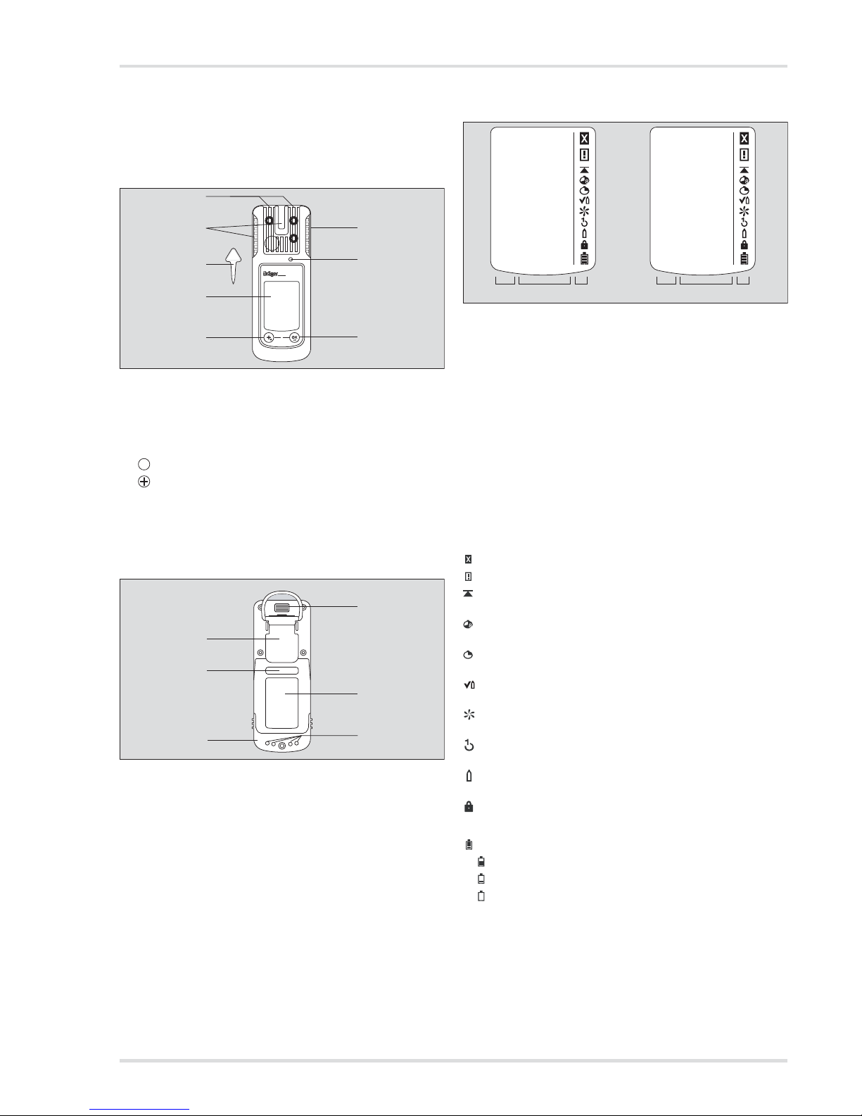
2.1.1 Front
2.1.2 Rear side
2.1.3 Display
Display for 4 measuring channels:
otherwise:
The following only shows the instrument version with
4 measuring channels.
2.1.4 Special symbols
1
Gas entry
2
Alarm LED
3
Horn
4
key
5
key
6
Display
7
Tool for changing sensor
1
IR interface
2
Fastening clip
3
Nameplate
4
Charging contacts
5
Power pack
6
Serial no.
00133366.eps
0
1
2
6
5
4
3
2
X-am 2500
7
OK
00233366.eps
2
1
4
6
3
5
1
Measured gas display with unit
2
Measuring value display
3
Special symbols
4
Measured gas display
5
Measured value display with unit
6
Special symbols
Fault message, see section 4.1 on page 16
Warning message, see section 4.1 on page 16
Display of peak values for all measured gases,
see section 4.1 on page 16
The exposure evaluation display (TWA) for measured
gases, e.g. H
2
S and CO, see section 4.1 on page 16
The exposure evaluation display (STEL) for measured
gases, e.g. H
2
S und CO, see section 4.1 on page 16
The instrument is set to the bump test function,
see section 3.4 on page 13
The instrument is set to the fresh air calibration function,
see section 5.2 on page 17
The instrument is set to the 1-button calibration/
adjustment function, see section 5.3 on page 18
The instrument is set to the single gas calibration
function, see section 5.3.1 on page 19
Function for password input is active, see section 4.4
on page 16
Battery / rechargeable battery 100 % full
Battery / rechargeable battery 2/3 full
Battery / rechargeable battery 1/3 full
Battery / rechargeable battery empty
00333366_de.eps
456
CH4
O
2
CO
123
CH4 %UEG
0.0
O2 Vol%
20.9
CO
ppm
0.0
H2S
ppm
0.0
%UEG
0.0
Vol%
20.9
ppm
0.0
Page 6
6 Dräger X-am 2500
Description
2.2 Intended use
Portable gas detection instrument for the continuous
monitoring of the concentration of several gases in the ambient
air within the working area and in explosion-hazard areas.
Independent measurement of up to 4 gases, in accordance
with the installed Dräger sensors.
Areas subject to explosion hazards, classified by zones
The instrument is intended for the use in areas that are at risk
for explosions in Zone 0, Zone 1 or Zone 2 or in mines at risk
due to black damp. It is intended for use within a temperature
range of -20 °C to +50 °C, and for areas in which gases of
explosion groups IIA, IIB or IIC and temperature class T3 or T4
(depending on the batteries and rechargeable battery) may be
present. For zone 0, the temperature class is limited to T3.
If used in mines, the instrument is only to be used in areas
known to have a low risk of mechanical impact.
Areas subject to explosion hazards, classified by divisio ns
The instrument is intended for the use in areas that are at risk
for explosions of Class I&II, Div. 1 or Div. 2. It is intended for
use within a temperature range of –20 °C to +50 °C, and for
areas in which gases or dusts of groups A, B, C, D or E, F, G,
and temperature class T3 or T4 (depending on the batteries
and rechargeable battery) may be present.
2.3 Approvals
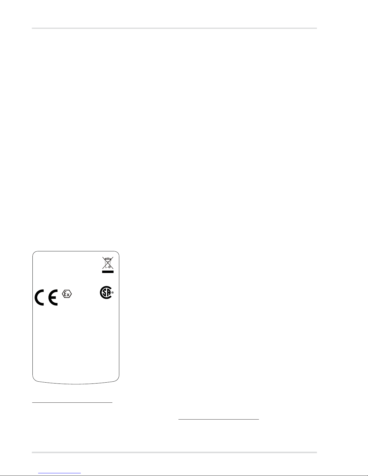
2.3.1 Marking
Serial no.
1
on separate sticker
2.3.2 Permitted power packs
Power pack 83 22 237;
approved as type ABT 0100
Temperature class T4
–20 °C b Ta b +50 °C
use with alkaline batteries
Duracell Procell MN1500
2
Temperature class T3
–20 °C b Ta b +40 °C
use with NiMH rechargeable batteries
GP 180AAHC
2
(1800 mAh)
or with alkaline batteries
Varta Type 4006
2
Varta Type 4106
2
Panasonic LR6 Powerline
NiMH power pack T4 (order no. 83 18 704);
approved as HBT 0000
Temperature class T4
–20 °C b Ta b +50 °C
NiMH power pack T4 HC (order no. 83 22 244);
approved as HBT 0100
Temperature class T4
–20 °C b Ta b +50 °C
CE marking: Electromagnetic compatibility
(Directive 2004/108/EC)
Explosion protection (Directive 94/9/
EEC)
1 The year of construction is coded by the third capital letter of the
serial number: D = 2012, E = 2013, F = 2014, H = 2015, J = 2016,
K = 2017, L = 2018, etc.
Example: Serial number AREH-0054, the third letter is E, so the
year of manufacture is 2013.
Dräger Safety Type: MQG 0011
23560 Lübeck, Germany
I M1 / II 1G for comb. sensor
I M2 / II 2G Um=4.6V Im=1.3A
Ex ia I/IIC T3 Ma/Ga Ex d ia I/IIC T4/T3 Mb/Gb
BVS 10 ATEX E 080X IECEx BVS 10.0053X
ANZEx 11.2003X PFG 10 G 001X
Intrinsically
safe Ex ia, CSA 11 1800517
CSA:
Class I, Div. 1, Gr. A,B,C,D TC T4/T3
Class I, Zone 0, A/Ex ia IIC T3 /Ga
Class I, Zone 1, A/Ex d ia IIC T4/T3 /Gb
-20°C Ta +50/+40°C: see Battery Pack!
For TC T4/T3: see Battery Pack!
Warning: Read manual for safety precautions.
Do
not change or charge batteries in haz loc.
≤ ≤
0158
C22.2 No.152
C US
2 Not subject to BVS10 ATEX E 080X and PFG 10 G 001X
performance approval.
Page 7
Description
Dräger X-am 2500 7
2.3.3 Safety Instructions
Only the functions of the part of the equipment used to measure
flammable gases are measured as part of the CSA approval.
WARNING
Do not replace or charge batteries in potentially
explosive areas. Explosion hazard!
Charge the NiMH power pack T4 (type HBT 0000) or
T4 HC (type HBT 0100) with the associated Dräger
charger. Charge NiMH single cells for ABT 0100
battery holder in accordance with the manufacturer's
specifications. Ambient temperature during the
charging process: 0 to +40 °C.
To reduce the danger of explosion, do not mix new
batteries with old batteries and do not mix batteries
made by different manufacturers.
Always disconnect the instrument from the power pack
before carrying out any maintenance operations.
Substitution of components may impair intrinsic safety .
Only use power packs ABT 0100 (order no. 83 22 237),
HBT 0000 (order no. 83 18 704) or HBT 0100 (order no.
83 22 244). See marking on power pack for approved
batteries and related temperature classes.
Not tested in an oxygen-enriched atmosphere
(>21 % O
2
).
High off-scale readings may indicate an explosive
concentration.
CAUTION
Re. CSA approval:
Before use each day, test the sensitivity using a known
concentration of the gas being measured,
corresponding to between 25 and 50 % of the
maximum concentration. The accuracy must be in
a range of 0 to +20 % of the actual value. Correct the
accuracy via adjustment if necessary.
!
!
Page 8
8 Dräger X-am 2500
Use
3Use
3.1 Preparations for use
z Before using the instrument for the first time, insert the
batteries provided or a charged NiMH power pack T4
(type HBT 0000; order no. 83 18 704) / T4 HC
(type HBT 0100; order no. 83 22 244), see section 3.1.2
on page 9.
z The instrument is now ready for operation.
3.1.1 Charging the batteries
z To maintain the lifetime of the batteries, charging is
temperature controlled and only performed in a temperature
range of 5 to 35 °C. When outside this temperature range,
the charging automatically interrupted and automatically
recommenced after the temperature range has been
reached again.
z The charging time is typically 4 hours.
z A new NiMH power pack reaches its full capacity after three
complete charging/discharging cycles.
z Never store the instrument for extended periods without
being connected to a power source (maximum of
2 months) because the internal buffer battery will drain.
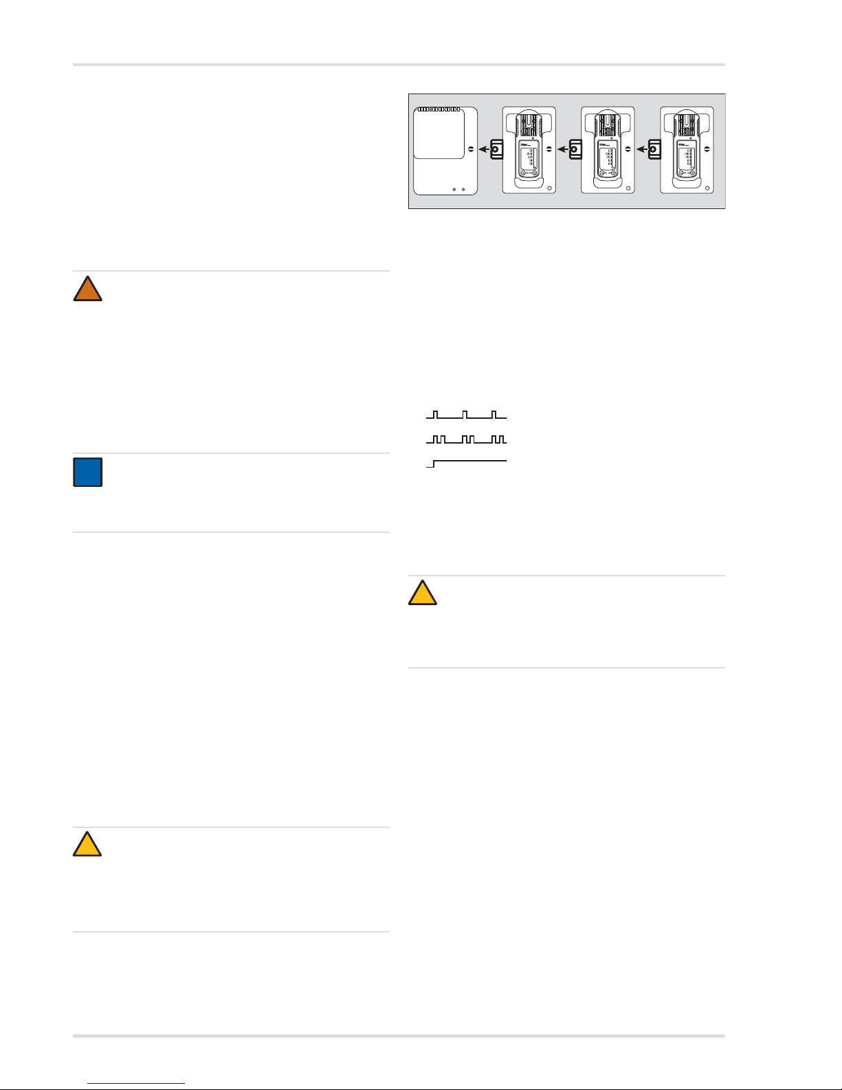
Charging with the multiple charging station
z A maximum of 20 instruments can be charged at the same
time on the power pack (order no. 83 18 805) of the
multiple charging station.
z When attaching the charging modules, disconnect the
power pack from the mains supply!
z Position the instrument on an even and level surface.
1. Turn the slots of the interlock into a horizontal position by
using a screwdriver or coin.
2. Insert the fastening lug (2) of the charger module
(simultaneous power feed) until it engages.
3. Close the lock (1) with a quarter turn (slot is positione d
vertically).
4. Attach additional charging modules in the same way.
5. Connect the power pack to the mains.
{ The green "Mai ns" LED (1) is on.
6. Insert the switched off instrument into the charger module.
{ Display LED (5) on the charging cradle:
z If a fault occurs:
{ Remove the instrument from the charging module and
insert it again.
z If the fault still occurs, have the charging module repaired.
{ It takes approx. 4 hours to fully charge an empty
rechargeable battery.
z In the event of a short circuit or if the power pack is
overloaded:
{ The red "Overload" LED (3) is on, and an audible
alarm sounds.
{ After the fault has been corrected, the alarm is switched
off automatically and the charging process is restarted.
{ In the event of a power failure, the instruments already
charged will be protected from discharging.
WARNING
Explosion hazard!
Do not charge underground or in explosion hazard areas!
The chargers are not designed in accordance with the
regulations for fire damp and explosion protection.
Charge the NiMH power pack T4 (type HBT 0000) or
T4 HC (type HBT 0100) with the associated Dräger
charger. Charge NiMH single cells for ABT 0100
battery holder in accordance with the manufacturer's
specifications. Ambient temperature during the
charging process: 0 to +40 °C.
NOTICE
Even if the instrument is not used, Dräger
recommends storing the instrument in the charging
cradle (chargingmodule X-am 1/2/5000, order no.
83 18 639).
CAUTION
Always connect or disconnect the charging modules
individually and not in groups in order to prevent the
charging station from becoming damaged. During
transportation, the power pack and the charging
modules should also always be handled individually
and without inserted instruments.
!
i
i
!
Charging
Fault
Full
CAUTION
A short circuit of the charging contacts in the charging
modules, e. g., by metallic objects that have fallen in,
does not result in damage to the charging station.
It should, however, be avoided due to possible heating
hazards and incorrect displays on the charger module.
02733366.eps
0
2
1
0
2
1
0
2
1
1
Ex
%UEG
CO
2
ppm
O
2
Vol%
CO
ppm
H
2S
ppm
Ex
%UEG
CO
2
ppm
O
2
Vol%
CO
ppm
H
2S
ppm
Ex
%UEG
CO
2
ppm
O
2
Vol%
CO
ppm
H
2S
ppm
X-am 2500
X-am 2500 X-am 2500
!
Page 9
Use
Dräger X-am 2500 9
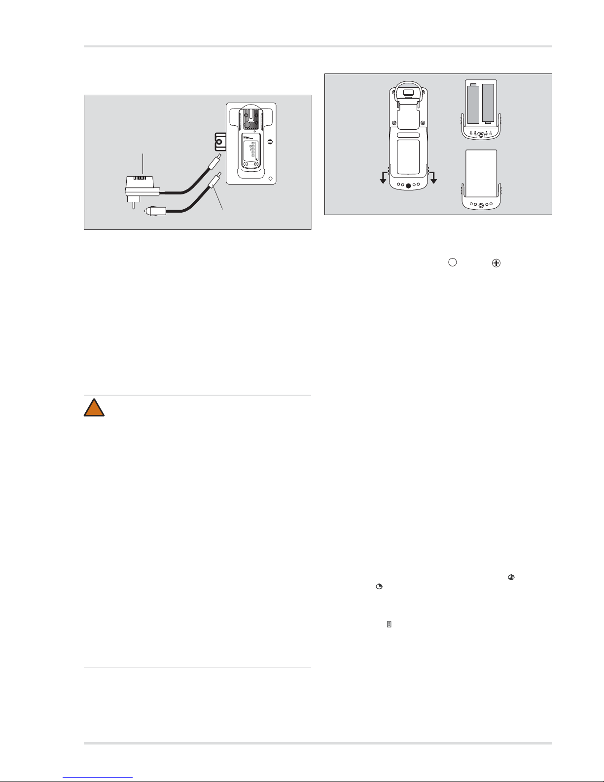
Charge using charger module and plug-in power pack or
vehicle charging adapter
z When using the power pack (order no. 83 16 994), up to
5 instruments can be charged at the same time, with power
pack (order no. 83 15 635) up to 2 instruments.
z The power pack contained in the rechargeable battery and
charging set (order no. 83 18 785) is suitable for charging
one instrument.
z When using the vehicle charging adapter (order no.
45 30 057) it is recommended that you supply every
charging module separately.
z The charging process is carried out analogous to charging
with the multiple charging station.
3.1.2 Replacing the batteries / rechargeable batteries
1. Switching off the instrument: key and key are held
down simultaneously.
2. Loosen the screw (2.0 mm hexagon socket) on the power
pack and remove the power pack.
z With battery holder (order no. 83 22 237): Replace alkaline
batteries or NiMHy rechargeable batteries. Ensure correct
polarity.
z With the T4 NiMH power pack (type HBT 0000) / T4 HC
(type HBT 0100): Completely replace the power pack.
3. Insert the power pack into the instrument and tighten
the screw, the instrument switches on automatically.
After replacing the T4 NiMH power pack (type HBT 0000)/
T4 HC (type HBT 0100), a full charge is recommended.
After the batteries have been replaced:
z The settings and data are stored when the battery is replaced.
The sensors warm up again.
3.1.3 Switching on the instrument
1. Hold down the [OK] button for approx. 3 seconds until the
»3.2.1« countdown shown on the display has elapsed.
{ All the display se gments, including the visual, audible
and vibration alarms, are activated for a short time.
{ The software version is displayed.
{ The instrument performs a self-test.
{ The sensor that is up next for calibration/adjustment is
displayed with the remaining days until the next
calibration/adjustment e. g. » Ex %LEL CAL 20 «.
{ The time until the bump test interval elapses is
displayed in days, e.g. »bt123«.
{ All alarm thresholds A1 and A2 as well as »« (TWA)
1
and »« (STEL)3) for H2S and CO are displayed
consecutively.
{ During the warm-up period of the sensors, the respective
display of the measured value flashes and the special
symbol »« (for warning) is displayed. No alarms are
issued during the warm-up period of the sensors.
See the Technical Handbook for details regarding
accelerated warm-up.
2. Press the [OK] key to cancel the display of the activation
sequence.
WARNING
Explosion hazard!
Do not throw used batteries into fire or try to open them
by force.
Do not replace or charge batteries in a hazardous area.
Batteries / rechargeable batteries are part of the
Ex approval.
Only the following types may be used:
z Alkaline batteries – T3 – (non rechargeable!)
z Panasonic LR6 Powerline
z Varta Type 4106
1
(power one) or
z Varta Type 4006
1
(industrial)
z Alkaline batteries – T4 – (non rechargeable!)
z Duracell Procell MN1500
1
z NiMHy rechargeable batteries – T3 – (rechargeable)
z GP 180AAHC
1
(1800 mAh) max. 40 °C ambient
temperature.
Charge the NiMH power pack T4 (type HBT 0000) or
T4 HC (type HBT 0100) with the associated Dräger
charger. Charge NiMH rechargeable batteries for
battery holder ABT 0100 in accordance with the
manufacturer's specifications. Ambient temperature
during the charging process: 0 to +40 °C.
1) Not part of the measurement performance tests BVS10 ATEX E 080X
and PFG 10 G 001X.
02833366.eps
83 16 994 (100 ... 240 V)
83 15 635 (100 ... 240 V)
45 30 057
0
Ex
%UEG
CO
2
ppm
O
2
Vol%
CO
ppm
H
2S
ppm
X-am 2500
!
1 Only when activated in the instrument configuration. Delivery status:
not activated.
02633366.eps
1
2
3
–
+
–
+
OK
Page 10
10 Dräger X-am 2500
Use
3.1.4 Switching off the instrument
z Press and hold the [OK] key and [+] key simultaneously
until the countdown »3.2.1« shown on the display has
elapsed.
Before the instrument is switched off, the visual,
audible and vibration alarms are activated for a short time.
3.2 Before entering the workplace
1. Switch on the instrument. The current measured values are
shown in the display.
2. Observe any warning »« or fault messages »«.
3. Check that the gas inlet opening on the instrument is
not covered.
WARNING
Before making safety-related measurements, check
the adjustment and adjust as needed, and check all
alarm elements. A bump test must be performed
according to the national regulations.
The instrument can be operated normally. If the warning
message does not disappear automatically during
operation, the instrument must be serviced after the end
of use.
The instrument is not ready to measure and requires
maintenance.
WARNING
Fractions of catalytic poisons in the measuring gas
(e.g. volatile silicone, sulphur, heavy metal compounds
or halogenated hydrocarbon) can damage the
CatEx sensor. If the CatEx sensor can no longer be
calibrated to the target concentration, the sensor must
be replaced.
In case of measurements in an oxygen-deficient
atmosphere (<8 Vol.-% O
2
) the CatEx sensor may
show incorrect displays; in this case, a reliable
measurement with a CatEx sensor is not possible.
In an oxygen enriched atmosphere (>22 Vol.-% O
2
),
the electrical operational safety cannot be guaranteed;
switch off instrument or leave work station.
!
!
Page 11
Use
Dräger X-am 2500 11
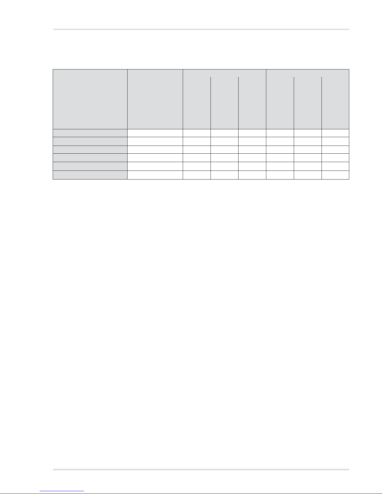
3.3 Configuration
3.3.1 Standard gas configuration
DrägerSensor Measuring range
1
Alarm A1
1)
Alarm A2
1)
threshold
can be acknowledged
self-latching
threshold
can be acknowledged
self-latching
CatEx 125 PR [%LEL] 0 to 100 20 yes no 40 no yes
XXS O2 [Vol.-%] 0 to 25
19
2
no yes 23 no yes
XXS CO [ppm] 0 to 2000 30 yes no 60 no yes
XXS H2S LC [ppm] 0 to 100 1.6 yes no 3.2 no yes
XXS NO2 [ppm] 0 to 50 5 yes no 10 no yes
XXS SO2 [ppm] 0 to 100 1 yes no 2 no yes
1) Different settings can be selected to meet customer requirements on delivery. The current setting can be checked and changed with
the Dräger CC Vision software.
A version of the CC-Vision software that can be used for Dräger X-am 2500 is available for download from the product page for the X-am 2500
at the following web address: www.draeger.com
2) With O
2
, A1 is the lower alarm threshold: an alarm is triggered if the value is too low.
Page 12

12 Dräger X-am 2500
Use
3.3.2 Standard instrument configuration
Changing the configuration: see “Replacing the sensors” on
page 21.
3.3.3 Configuring the device
To individually configure a standard-configuration device,
connect the device to a PC. The installed PC software
Dräger CC Vision is used for configuration.
z Observe the documentation and online help of the software.
z A version of the CC-Vision software that can be used for
Dräger X-am 2500 is available for download from the
product page for the X-am 2500 at the following web
address: www.draeger.com
3.3.4 Export data memory and display graphically
To read the database of the instrument and display it
graphically, the instrument must be connected with a PC.
The installed Dräger GasVision PC software is used for
exporting and displaying the database.
z Observe the documentation and online help of the software.
Bump test in Quick Menu
1
1) Different settings can be selected to meet customer requirements
on delivery. The current setting can be checked and changed with
the Dräger CC Vision software.
A version of the CC-Vision software that can be used for Dräger
X-am 2500 is available for download from the product page for the
X-am 2500 at the following web address: www.draeger.com
Quick bump test
Fresh air calibration in the
Quick Menu
1)
ON
Life sign - visual only
1)
ON
Switching off
1)
allowed
LEL factor
1)
(CH4) 4.4 (vol. %)
(4.4 vol. % corresponds to
100 %LEL)
Averaging time
1)
15 minutes for STEL
8 hours for TWA
WARNING
After a basic initialisation has been carried out with the
PC software Dräger CC Vision, individual alarm
settings may have been changed.
!
IR
Calibration cradle (order no. 83 18 752)
with inserted
USB DIRA with USB cable (order no. 83 17 409)
USB DIRA with USB cable
(order no. 83 17 409)
E-Cal module Dräger X-am 125
(order no. 83 18 754)
USB 1.1
USB 1.1
USB 1.1 / COM
00733366_en.eps
0
0
0
X-am 2500
Page 13

Use
Dräger X-am 2500 13
3.4 Running the bump test
3.4.1 Manual implementation without documentation of
the results in the instrument memory
1. Prepare a test gas cylinder,
the volume flow must be
0.5 l/min and the gas
concentration must be
higher than the alarm
threshold concentration
that is to be tested.
Example test gas cylinder
68 11130 = mixed gas with
50 ppm CO, 15 ppm H
2
S,
2.5 vol. % CH
4
, 18 vol. % O
2
2. Connect the test gas
cylinder with the calibration
cradle (order no. 83 18 752).
3. Vent the test gas into
a fume cupboard or into the
open air (with a hose connected to the second connector of
the calibration cradle).
4. Switch on the instrument and insert it into the calibration
cradle – press downwards until it engages.
5. Open the test gas cylinder valve to let test gas flow over
the sensors.
Recommendation: Wait until the instrument displays the
test gas concentration with sufficient tolerance –
Ex: ±20 % of the test gas concentration
1
O2: ±0.6 vol. %
1
TOX: ±20 % of the test gas concentration
1
Wait until at least alarm threshold A1 or A2 has been
exceeded, however.
If the alarm thresholds are exceeded, the instrument
displays the gas concentration in alternation with »A1« or
»A2« depending on the test gas concentration.
6. Close the test gas cylinder valve and remove the
instrument from the calibration cradle.
If the concentration has now fallen under the A1 alarm threshold:
z Acknowledge the alarm.
If the displays are outside of the above-mentioned ranges:
z Calibrating/adjusting the instrument, see section 5 on
page 17.
3.4.2 Menu implementation with the documentation of
results in the instrument memory
The setting to "Quick bump test" or "Accelerated bump test" is
made using the PC software Dräger CC Vision.
In the "Quick bump test" a check is carried out as to whether
or not the gas concentration has exceeded alarm threshold 1
(with oxygen, the test checks that alarm threshold 1 has not
been reached).
In the "Accelerated bump test" a check is carried out as to
whether or not the gas concentration has exceeded alarm
threshold 1 (with oxygen, the test checks that the alarm
threshold has not been reached) and whether or not the gas
concentration has reached the set bump test concentration.
Setting on delivery: Quick bump test.
1. Prepare a test gas cylinder, the volume flow must be 0.5 l/min
and the gas concentration must be higher than the alarm
threshold concentration that is to be tested.
Example test gas cylinder 68 11 130 = mixed gas with
50 ppm CO, 15 ppm H
2
S, 2.5 vol. % CH4, 18 vol. % O
2
2. Connect the test gas cylinder
with the calibration cradle
(order no. 83 18 752)).
3. Vent the test gas into a fume
cupboard or into the open
air (with a hose connected
to the second connector of
the calibration cradle).
4. Switch on the instrument and insert it into the calibration
cradle – press downwards until it engages.
5. Open the Quick menu and
select the bump test,
page 16.
The current gas
concentration values and
the special symbol » «
(for bump test) flash.
6. Press the key to start
the bump test.
7. Open the test gas cylinder
valve to let test gas flow
over the sensor.
If gas concentration exceeds
the alarm thresholds A 1 or
A 2 the corresponding alarm
will occur.
CAUTION
Never inhale the test gas. Health hazard! Observe the
hazard warnings of the relevant Safety Data Sheets.
1 Upon application of the Dräger mixed gas (order no. 68 11130) the displays
should be within this range.
00833366.eps
0,5 L/min
0
!
CAUTION
Never inhale the test gas. Health hazard! Observe the
hazard warnings of the relevant Safety Data Sheets.
00833366.eps
0,5 L/min
0
!
00933366_en.eps
CH4
%LEL
O
2
Vol%
CO
ppm
H
2S
ppm
OK
Page 14

14 Dräger X-am 2500
Use
Ending the bump test:
After the set bump test
concentration has been
reached or a gas alarm has
been triggered (with "Quick
bump test"):
z The display containing the
current gas concentration
changes with the display
»OK«.
z The bump test that was
carried out is documented
with the result and date in
the instrument memory .
8. Close the test gas cylinder
valve and remove the
instrument from the calibration cradle.
z If the concentration values have now fallen under the A1
alarm thresholds, the instrument returns to the measuring
mode.
z If the set bump test concentration is not reached within the
set time, an error is issued.
{ The fault message
» « appears and
» « is displayed
instead of the measured
value on the faulty
measuring channel.
{ In this case, repeat the
bump test or calibrate
the instrument, page 21.
The bump test can also be run
automatically. The "Bump Test
Station" is required for this function, see section 3.4.3 on
page 14.
3.4.3 Automatic implementation with the Bump
Test Station
Prerequisite:
The instrument first needs to be configured for the automatic
bump test using the Dräger CC-Vision PC sofware.
z Activating the instrument for the automatic bump test.
z Composition of test gas (mixed gas) – standard on delivery:
50 ppm CO, 15 ppm H
2
S, 2.5 vol. % CH4, 18 vol. % O
2
z Define which measuring channels should participate in the
automatic bump test. All measuring channels participate in
the bump test by default.
1. Prepare the Bump T e st Stat ion according to the instructions.
2. Switch on the instrument
and insert it into the
receptacle of the Bump Test
Station until it engages.
The bump test will be
started automatically.
The special symbol » «
(for bump test) flashes.
If a gas alarm (quick bump test) is initiated and the set
bump test concentration (Accelerated bump test) is
reached within the set time, the current gas concentration
will be displayed alternately with »OK«.
3. Remove the instrument from the Bump Test Station.
z If the concentration values have now fallen under the A1
alarm thresholds, the instrument returns to the measuring
mode.
z If there is no alarm during the bump test and the current
measurements do not reach the set target concentration
("Accelerated bump test" only), an error is issued.
{ The fault message
» « appears and
»« is displayed
instead of the measured
value on the faulty
measuring channel.
{ In this case, repeat the
bump test or calibrate
the instrument, page 21.
The bump test can also be run manually, see section 3.4.1 on
page 13.
The Dräger CC Vision PC software can be used to enable the
"Automatic calibration after incorrect bump test" option.
3.5 During use
z During operation, the measured values for every measured
gas are displayed.
z If a measuring range is exceeded or not reached,
the following displays are shown instead of the measured
value display:
z Excess concentrations of flammable materials can lead to
a lack of oxygen.
01033366_en.eps
CH4
%LEL
O
2
Vol%
CO
ppm
H
2S
ppm
01133366_en.eps
CH
4
%LEL
O
2
Vol%
CO
ppm
H
2
S
ppm
01333366.eps
0
Ex
%UEG
O
2
Vol%
CO
ppm
H
2S
ppm
»«
(measuring range exceeded) or
»«
(measuring range not reached).
01133366_en.eps
CH
4
%LEL
O
2
Vol%
CO
ppm
H
2
S
ppm
01133366_en.eps
CH
4
%LEL
O
2
Vol%
CO
ppm
H
2
S
ppm
Page 15

Use
Dräger X-am 2500 15
z For O
2
concentrations under 8 vol. % an error is indi cated
with »« at the ex-channel instead of the measuring
value as long as the measuring value falls below the prewarning threshold (only if measuring range is b100 %LEL,
not for >100 %LEL (heat conductance)).
z In the event of an alarm, the corresponding displays,
including the visual, audible and vibration alarms,
are activated, see section 6 on page 21.
If the measuring range is exceeded significantly at the CatEx
channel (very high concentration of flammable materials),
a blocking alarm is triggered. This CatEx blocking alarm is
either acknowledged automatically through a functional
oxygen channel (e. g. a channel free of warnings and defects)
or manually by switching the instrument on and off in fresh air.
No blocking alarm is triggered in the "methane" configuration
setting when a measuring range is exceeded, because the
unambiguousness of the display for methane is ensured via
a separate measurement of the heat conductivity.
After the measuring range of the TOX measuring channels has
been exceeded temporarily (up to one hour), checking the
measuring channels is not necessary.
3.6 Identifying alarms
An alarm is displayed visually, audibly and through vibration in
a specific pattern.
3.6.1 Concentration pre-alarm A1
The pre-alarm A1 is not latching and stops when the
concentration has dropped below the alarm threshold A1.
z In case of A1, a single tone is audible and the alarm
LED flashes.
Acknowledging the pre-alarm:
z Press the key. Only the audible alarm and the vibration
alarm are switched off.
3.6.2 Concentration main alarm A2
z In case of A2, a double tone is audible and the alarm
LED flashes twice.
After leaving the area, when the concentration has dropped
below the alarm threshold:
z Press the key. The alarm messages are switched off.
3.6.3 STEL / TWA exposure alarm
z The STEL and TWA alarm cannot be acknowledged
or cancelled.
z Switch off the instrument. The values for the exposure
evaluation are deleted after the instrument is switched
on again.
3.6.4 Battery pre-alarm
Acknowledging the pre-alarm:
z Press the key. Only the audible alarm and the vibration
alarm are switched off.
z The battery still lasts min. 20 minutes after the first battery
pre-alarm.
3.6.5 Battery main alarm
The battery main alarm cannot be acknowledged or cancelled:
z The device automatically switches off after 10 seconds.
z Before the instrument is switched off, the visual, audible
and vibration alarms are activated for a short time.
3.6.6 Instrument alarm
z The instrument is not ready for operation.
z For corrective measures, see“Replacing the sensors” on
page 21 to page 24.
z Contact maintenance or Draeger Service to rectify
the problem.
WARNING
After exposure to concentrations above 100 %LEL,
incorrect displays may occur at the CatEx channel.
Check the zero point and sensitivity and adjust it if
necessary before continuing to use the instrument in
a concentration range of 0 to 100 %LEL.
In the event of an impact load when using a CatEx
sensor in the Dräger X-am 2500 that causes the fresh
air display to deviate from zero, the zero point and
sensitivity must adjusted.
Intermittent alarm:
Display »A1« and measured value alternating:
WARNING
Risk of fatal injury! Leave the area immediately. A main
alarm is self-latching and cannot be acknowledged or
cancelled.
Intermittent alarm:
Display » A2 and measured value alternating:
!
OK
!
WARNING
Leave the area immediately. After this alarm,
the deployment of personnel is subject to the relevant
national regulations.
Intermittent alarm:
Display »A2« and »« (STEL) or »« (TWA) and
measured value alternating:
Intermittent alarm:
Flashing special symbol »« on the right
side of the display:
Intermittent alarm:
Flashing special symbol »« on the right side
of the display:
Intermittent alarm:
Special symbol »« displayed on the right
side of the display:
OK
!
OK
Page 16

16 Dräger X-am 2500
Menu functions
4 Menu functions
4.1 Activating the Info mode
z In measuring mode, press the key for approx. 3 seconds.
z If any warning or fault messages exist, the corresponding
information or error codes will be displayed (see section 8
on page 22).
z Press the key successively for the next display.
z The peak values and the exposition values TWA
1
and
STEL
1)
are displayed.
z If no key is pressed for 10 seconds, the instrument returns
automatically to measuring mode.
4.2 Opening Info-Off Mode
z When the instrument is in a deactivated state, press the
key.
The name of the gas, measuring unit, and measuring range
limit value are displayed for all channels.
z Pressing the key again exits the Info Off mode
(or via timeout).
4.3 Quick Menu
4.3.1 Quick menu functions
4.3.2 Opening the Quick Menu
On delivery, only the fresh air calibration is activated in the
Quick Menu. The PC software Dräger CC Vision can be used
to activate the bump test for the quick menu and/or the function
for displaying and deleting peak values.
1. In measuring mode, press the key three times.
If no functions have been activated in the quick menu,
the instrument remains in measuring mode.
2. Y ou can select the activated functions of the quick menu by
pressing the key.
{ Press the key to call the selected function.
{ Press the key to cancel the active function and to
switch to measuring mode.
{ If no key is pressed for 60 seconds, the instrument
returns automatically to measuring mode.
4.3.3 Quick menu "Displaying and deleting peak values"
After the function has been
selected, the current peak
values are displayed; the peak
values special symbol appears
in the display at the same time.
1. The peak values can be
deleted by pressing the
key for 5 sec. and the
adjacent display appears,
for example.
2. Press the key to end
the function.
4.4 Calibration Menu
4.4.1 Calibration menu functions
4.4.2 Open the Calibration Menu
z The calibration menu can only be accessed by entering
a password.
Password on delivery: »001«
z The default password on delivery can be changed using
the PC software Dräger CCVision.
1 Only when activated in the instrument configuration. Delivery status:
not activated.
Warning messages are displayed. Numerical codes
of warning messages: see section 8.1 on page 22.
key
Fault messages are displayed. Numerical codes of
fault messages: see section 8.2 on page 24.
key
The peak values = the maximum measured values in
the case of, e.g., CO, H
2
S, ... or the minimum
measured values in the case of O
2
within the storage
interval are displayed
key
The average values of the exposures based on a shift
of, e.g., 8 hours (TWA) of all the active sensors for the
exposure evaluation are displayed
key
The short-term values (STEL) = average values of
the concentrations over the average value duration
of all the active sensors for th e exposure evaluation
are displayed
key
The instrument is in measuring mode again
Bump test see section 3.4 on page 13
Fresh air calibration, see section 5.2 on page 17
Display and clearing the peak values, see section 4.3.3
on page 16
OK
OK
OK
OK
OK
OK
OK
OK
Fresh air calibration, see section 5.2 on page 17
1-button calibration, see section 5.3 on page 18
Single gas calibration, see section 5.3.1 on page 19
OK
00433366_en.eps
CH4
%LEL
O
2
Vol%
CO
ppm
H
2S
ppm
00533366_en.eps
CH4
%LEL
O
2
Vol%
CO
ppm
H
2S
ppm
OK
OK
Page 17

Calibrate instrument
Dräger X-am 2500 17
1. In measuring mode, press the key for at least 4 seconds.
The function for entering the password is selected.
The special symbol » « (for the "enter password" function)
is displayed.
The display shows »000«,
with the first digit flashing.
2. Use the key to set the
flashing digit.
3. Press the key, the
second digit starts flashing.
4. Use the key to set the
flashing digit.
5. Press the key, the third
digit starts flashing.
6. Use the key to set the
flashing digit.
7. Press the key to confirm
the password once it has
been set completely.
8. The calibration menu functions can now be selected by
pressing the key.
{ Press the key to call the selected function.
{ Press the key to cancel the active function.
{ If no key is pressed for 10 minutes, the instrument
automatically returns to measuring mode.
5 Calibrate instrument
z Adjustment may not be possible due to instrument and
channel errors.
z Allow the sensors to warm up before the calibration!
z Warming-up time: see instructions for use / data sheets for
the Dräger sensors installed (product page for X-am 2500
at www.draeger.com).
5.1 Adjustment interval:
z Observe the relevant specifications in the Instructions for
Use/data sheets of the Dräger Sensors installed.
z For critical applications, observe the recommendations in
EN 60079-29-2
1
or EN 45544-42 and national regulations.
We recommend that you adjust all the channels after
6months.
z Improving the zero point accuracy – perform fresh air
calibration, page 17.
z Set the sensitivity of all sensors to the value of the
test gas – carry out the 1-button calibration, page 18.
z Set the sensitivity of a sensor to the value of the test gas –
span calibration/adjustment, page 19.
5.2 Run fresh air calibration
To improve the zero-point accuracy, a fresh air calibration can
be carried out.
z Calibrate the instrument to fresh air, free of measured
gases or other interfering gases.
z Sensors which have not warmed up or which are faulty
prevent a calibration.
{ In the case of sensors which are in the warm-up phase,
the message » 159 « is displayed with the special
symbol » « (for warning message).
{ In the case of a sensor or instrument error,
the message » 109 « is displayed with the special
symbol » « (for a fault message).
{ The message is cleared after 5 seconds and the
function is available again in the menu.
z During the fresh air calibration the zero point of all sensors
(with the exception of the DrägerSensor XXS O
2
) are set
to 0.
z In the case of the DrägerSensor XXS O
2
, the display is set
to 20.9 vol. %.
1. Switch on instrument.
2. Depending on instrument configuration:
{ Open the Quick menu and select the fresh air
calibration function, page 16.
or
{ Open the Calibration menu and select the fresh air
calibration function, page 16.
z The current gas concentra-
tion values flash.
z When the measured values
have stabilized:
3. Press the key to carry
out the fresh air calibration.
z The display containing the
current gas concentration
changes with the display
»OK«.
4. Press the key to confirm
the calibration or wait for
approx. 5 seconds.
WARNING
Always calibrate the zero-point before span.
Otherwise, the calibration will contain errors!
1 EN60079-29-2 – Guidelines for selection, installation, use and
maintenance of instruments for the detection and measurement of
flammable gases and oxygen.
2 EN 45544-4 – Electrical instruments for the direct detection and
direct concentration measurement of toxic gases and vapours –
Part 4: Guide for selection, installation, use and maintenance.
CAUTION
Never inhale the test gas. Health hazard! Observe the
hazard warnings of the relevant Safety Data Sheets.
00633366.eps
OK
OK
OK
OK
!
!
01333366_en.eps
CH
4
%LEL
O
2
Vol%
CO
ppm
H
2
S
ppm
OK
01433366_en.eps
CH4
%LEL
O
2
Vol%
CO
ppm
H
2S
ppm
OK
Page 18

18 Dräger X-am 2500
Calibrate instrument
If a fault has occurred during the fresh air calibration:
z The fault message » «
appears and » « is
displayed for the respective
sensor instead of the
measured value.
z In this case, repeat the
fresh air calibration.
z Replace the sensor if
necessary, page 21.
5.3 1-button calibration
z All sensors approved by the Dräger CC-Vision PC program
are included in the 1-button calibration.
z In the case of the 1-button calibration, the sensitivity of all
sensors is set to the value of the test gas.
When using test gas cylinder 68 111 30 = mixed gas with
50 ppm CO, 15 ppm H
2
S, 2.5 vol. % CH4, 18 vol. % O2.
z If a mixed gas with another
composition is used,
the specified concentration
values in the instrument
must be changed to the
target values of the mixed
gas used using the PC
software "Dräger CCVision".
1. Connect the test gas
cylinder with the calibration
cradle.
2. Vent the test gas into a fume
cupboard or into the open
air (with a hose connected
to the second connector of the calibration cradle).
3. Switch on the instrument
and insert it into the
calibration cradle until it
engages.
4. Call the calibration menu,
enter the password and select the 1-button calibration
function, page 16.
5. Press the key to start
the 1-button calibration.
6. Open the test gas cylinder
valve to let test gas flow
over the sensor.
The currently displayed
measured values start
to flash.
The flashing stops after a static measured value has
been reached.
The calibration is now carried out automatically.
The displayed measured values change to the values
according to the gas supplied.
7. The automatic stability monitoring can be overridden by
pressing the key. A calibration is carried out immediately .
If it is detected that no test gas has been supplied,
the 1-button calibration is cancelled. The channels then
display »n/a«. If only one sensor is included in the 1-button
calibration, an adjustment is carried out in any case when
the key is pressed.
01533366_en.eps
CH
4
%LEL
O
2
Vol%
CO
ppm
H
2
S
ppm
NOTICE
If no sensors have been approved by the Dräger
CC-Vision PC program for the 1 button calibration,
the 1-button calibration will not be available.
CAUTION
Never inhale the test gas. Health hazard! Observe the
hazard warnings of the relevant Safety Data Sheets.
i
i
00833366.eps
0,5 L/min
0
!
01633366_en.eps
CH4
%LEL
O
2
Vol%
CO
ppm
H
2S
ppm
OK
OK
OK
Page 19

Calibrate instrument
Dräger X-am 2500 19
When the calibration is completed and the displayed
measured values have stabilised:
z The display containing the
current gas concentration
changes with the display
»OK«.
8. Press the key or wait
for 5 seconds to quit the
calibration.
z The instrument changes to
the measuring mode
9. Close the test gas cylinder
valve and remove the
instrument from the
calibration cradle.
If a fault occurs during the 1-button calibration:
z The fault message » «
appears and » « is
displayed for the respective
sensor instead of the
measured value.
z In this case, repeat
the 1-button calibration or
carry out a single gas
calibration, see section
5.3.1 on page 19.
z Replace the sensor if
necessary, page 21.
5.3.1 Calibrating the sensitivity for an individual
measuring channel
z The span calibration can be carried out specifically for
individual sensors.
z In the case of the span calibration, the sensitivity of the
selected sensor is set to the value of the test gas used.
z Use a standard test gas.
Allowed test gas concentration:
1. Connect the test gas
cylinder with the calibration
cradle.
2. Vent the test gas into a fume cupboard or into the open air
(with a hose connected to the second connector of the
calibration cradle).
3. Switch on the instrument and insert it into the calibration
cradle.
4. Press the [+] ke y and keep it pressed for 5 seconds to
open the calibration menu, enter the password and select
the single gas calibration function, page 16.
5. Press the key to start the channel selection.
z The display flashes the gas
of the first measuring
channel, e.g. » Ex %LEL «.
6. Press the key to start
the calibration function of
this measuring channel,
or use the key to
select another measuring
channel (O
2
- vol. %, H2S -
ppm or CO - ppm).
5.3.2 Sensitivity calibration for CatEx
If the measuring range end
value < = 100 LEL, the
calibration for catalytic effect is
suggested.
Display on channel selection:
1. Press the key to start the
catalytic effect calibrat io n.
2. Press the key to select
the next sensor.
Ex: 40 to 100 %LEL
O
2
10 to 25 vol. %
CO: 20 to 999 ppm
H
2
S: 5 to 99 ppm
Test gas concentration of
other gases: see Instructions
for Use for the respective
DrägerSensors.
01733366_en.eps
CH
4
%LEL
O
2
Vol%
CO
ppm
H
2
S
ppm
OK
01833366_fr_es.eps
CH4
%LIE
O
2
Vol%
CO
ppm
H
2S
ppm
00833366.eps
0,5 L/min
0
CAUTION
Never inhale the test gas. Health hazard! Observe the
hazard warnings of the relevant Safety Data Sheets.
!
OK
01933366_en.eps
CH4
%LEL
CO
2
ppm
O
2
Vol%
CO
ppm
H
2S
ppm
NH
3
ppm
OK
02033366.eps
CH4
VOL%
CO
2
ppm
O
2
Vol%
CO
ppm
H
2S
ppm
NH
3
ppm
OK
02133366.eps
O2
VOL%
O
2
Vol%
CO
ppm
H
2S
ppm
NH
3
ppm
Page 20

20 Dräger X-am 2500
Calibrate instrument
If the measuring range end
value >100 LEL, the calibration
for catalytic effect and heat
conduction is suggested,
display on channelselection:
3. After pressing the key,
the following appears on
the display:
4. Press the key to start the catalytic effect calibration.
5. After pressing the key,
the following appears on
the display:
6. Press the key to start the heat conduction calibration.
7. key can be pressed to
select the next sensor.
8. Press the key to carry
out the calibration of the
selected measuring channel.
The calibration gas
concentration is displayed
9. Press the key to
confirm the calibration gas
concentration or use the [+]
key to change the calibration
gas concentration and
complete the process by
pressing the key.
The measurement value
flashes.
10.Open the te st gas cylinder valve to let test gas flow over
the sensor.
The displayed, flashing measurement value changes to the
value according to the supplied test gas.
When the displayed measurement value has stabilised:
11.Press the key to carry out the calibration.
The display containing the
current gas concentration
changes with the display
»OK«.
12.Press the key or wait for
approx. 5 seconds to quit
the calibration of this
measuring channel.
The next measuring channel
appears for calibration.
After the calibration of the
last measuring channel,
the instrument changes to
the measuring mode.
13.Close the test gas cylin der
valve and remove the instrument from the calibration
cradle.
If a fault has occurred during the sensitivity calibration:
z The fault message » «
appears and » « is
displayed for the respective
sensor instead of the
measured value.
z In this case, repeat the
calibration.
z Replace the sensor if
necessary, page 21.
Notice for the adjustment of the ex-channel to nonane as
a measuring gas:
z During the calibration of the ex-channel, propane can be
used as a substitute calibration gas.
z When using propane to adjust the ex-channel to nonane,
the display must be set to twice the used test gas
concentration.
Notice for the use in subsurface mining:
z For the calibration of the ex-channel to the measuring gas
methane, the display of the instrument must be set to
a value of 5 % (relative) higher than the used test gas
concentration.
02033366.eps
CH4
VOL%
CO
2
ppm
O
2
Vol%
CO
ppm
H
2S
ppm
NH
3
ppm
02233366_en.eps
CH
4
VOL%
<= 100%LEL
OK
OK
02333366_en.eps
CH4
VOL%
> 100%LEL
OK
02133366.eps
O2
VOL%
O
2
Vol%
CO
ppm
H
2S
ppm
NH
3
ppm
OK
OK
OK
OK
02433366_en.eps
CH
4
%LEL
OK
02533366_en.eps
CH4
%LEL
CO
2
ppm
O
2
Vol%
CO
ppm
H
2S
ppm
NH
3
ppm
Page 21

Operation with pump
Dräger X-am 2500 21
6 Operation with pump
With Dräger Pump X-am 1/2/5000
Accessories:
Dräger Pump X-am 1/2/5000, sampling hose and probes,
see section 12 on page 31.
Commissioning and performing the measurement:
z Refer to the Instructions for Use of the Dräger
Pump X-am 1/2/5000.
With manual pump adapter and rubber ball pump
Accessories:
For manual pump adapter, rubber ball pump, sampling hose
and probes, see section 12 on page 31.
Commissioning and performing the measurement:
z Refer to the Instructions for Use of the accessories used.
Observe the following during measuring mode with pump
z Wait for the flushing time to elapse:
Before every measurement, flush the Dräger sampling
hose or the Dräger probes with the air sample to be
measured.
z A flushing phase is necessary to eliminate or minimise all
effects associated with the use of a sampling hose or
a probe, e.g. memory effects, dead volume.
z The duration of the flushing phase depends on factors such
as type and concentration of the gas or vapour to be
measured, material, length, diameter, and age of the
sampling hose or probe. Generally, when using a sampling
hose (new, dry, clean), a typical flushing time of approx.
3 seconds is required for each metre. This flushin g time
applies in addition to the sensor response time (see the
Instructions for Use for the gas detection instrument used).
Example:
In the case of a sampling hose with a length of 10 m,
the flushing time is approx. 30 seconds and the sensor
response time is in addition approx. 60 seconds.
Therefore, the total time before reading the gas measuring
instrument is approx. 90 seconds.
The flow-rate alarm is delayed by 10 to 30 seconds
depending on the length of the hose.
7 Replacing the sensors
v To replace the sensors of the instrument, connect the
instrument with a PC.
v Replace the sensors using the PC program Dräger CC Vision.
Next:
v Conduct the fresh air calibration page 17.
and then:
v Calibrating sensitivity:
either
perform 1-button calibration, page18
or
run sensitivity calibration, see page19.
IR
Calibration cradle (order no. 83 18 752)
with inserted
USB DIRA with USB cable (order no. 83 17 409)
USB DIRA with USB cable
(order no. 83 17 409)
E-Cal module Dräger X-am 125
(order no. 83 18 754)
USB 1.1
USB 1.1
USB 1.1 / COM
00733366_en.eps
0
0
0
X-am 2500
Page 22

22 Dräger X-am 2500
Troubleshooting
8 Troubleshooting
List of the numerical codes of the warning and fault messages
in the info mode, see page 16.
8.1 Warning messages
Fault Cause Remedy
Not possible to switch on the instrument Discharged power pack Charge the power pack, page 8.
Discharged alkaline batteries Insert new alkaline batteries, page 21.
Not possible to switch off the instrument The instrument is not set to measuring
mode
Select measuring mode.
The instrument is configured to "Disable
prohibited"
Configure the instrument to "Disable allowed"
with Dräger CC Vision.
Display »––« Measuring range calibrated/adjusted
incorrectly
Recalibrate/adjust the measuring range,
page 21.
Electronics or sensors defective Must be repaired by Service.
Special symbol » « and
displayed numerical code:
Cause Remedy
152 Customer's service life counter about to elapse Reset the service life counter using Dräger
CC Vision.
153 Database 90 % full Read the database soon and clear memory
afterwards.
154 Database full Read the database and clear memory.
155 Interval for bump test elapsed Conduct the bump test page 21.
159 Calibration not possible. The menu function
cannot be carried out because of a message
which is preventing the function (e.g. sensors
in warm-up phase).
Determine the message code via the info menu
and switch it off, if necessary.
251 DrägerSensor CatEx 125 PR warming up Wait until warm-up time is complete.
252 DrägerSensor CatEx 125 PR warming up Wait until warm-up time is complete.
253 Ex concentration has drifted into the
negative range
Conduct the fresh air calibration page 17.
254 The temperature is too high Operate the instrument within the allowed
temperature range.
255 The temperature is too low Operate the instrument within the allowed
temperature range.
256 Calibration interval for DrägerSensor CatEx
125 PR has expired
Perform sensitivity calibration for DrägerSensor
CatEx 125 PR, page 19.
257 Alarm threshold A2 is set to greater than
60 %LEL
Set alarm threshold to less than 60 %LEL.
271 Heat conductance calibration interval for
DrägerSensor CatEx 125 PR has expired
Perform sensitivity calibration for DrägerSensor
CatEx 125 PR, page 19.
351 DrägerSensor XXS EC1 is warming up Wait until warm-up time is complete.
352 DrägerSensor XXS EC1 is warming up Wait until warm-up time is complete.
353 EC1 concentration has drifted into the
negative range
Conduct the fresh air calibration page 17.
354 The temperature is too high Operate the instrument within the allowed
temperature range.
355 The temperature is too low Operate the instrument within the allowed
temperature range.
Page 23

Troubleshooting
Dräger X-am 2500 23
356 The calibration interval for DrägerSensor XXS
EC1 has elapsed
Run sensitivity calibration for DrägerSensor
XXS EC1, page 19.
357 Alarm threshold A2 is set to greater than
60 %LEL
Set alarm threshold to less than 60 %LEL.
451 DrägerSensor XXS EC2 in the warm-up phase Wait until warm-up time is complete.
452 DrägerSensor XXS EC2 in the warm-up phase Wait until warm-up time is complete.
453 EC2 concentration has drifted into the
negative range
Conduct the fresh air calibration page 17.
454 The temperature is too high Operate the instrument within the allowed
temperature range.
455 The temperature is too low Operate the instrument within the allowed
temperature range.
456 The calibration interval for DrägerSensor
XXS EC2 has elapsed
Run sensitivity calibration for DrägerSensor
XXS EC 3, page 19.
457 Alarm threshold A2 is set to greater than
60 %LEL
Set alarm threshold to less than 60 %LEL.
551 DrägerSensor XXS EC3 in the warm-up phase Wait until warm-up time is complete.
552 DrägerSensor XXS EC3 in the warm-up phase Wait until warm-up time is complete.
553 EC3 concentration has drifted into the
negative range
Conduct the fresh air calibration page 17.
554 The temperature is too high Operate the instrument within the allowed
temperature range.
555 The temperature is too low Operate the instrument within the allowed
temperature range.
556 The calibration interval for DrägerSensor
XXS EC3 has elapsed
Run sensitivity calibration for DrägerSensor
XXS EC 3, page 19.
557 Alarm threshold A2 is set to greater than
60 %LEL
Set alarm threshold to less than 60 %LEL.
575 The calibration interval for the compensation
electrode has elapsed
Run sensitivity calibration for the compensation
electrode.
576 Calibration requested due to overgassing Run sensitivity calibration for the compensation
electrode.
651 DrägerSensor XXS EC 4 in the warm-up phase Wait until warm-up time is complete.
652 DrägerSensor XXS EC 4 in the warm-up phase Wait until warm-up time is complete.
653 EC 4 concentration has drifted into the
negative range
Conduct the fresh air calibration page 17.
654 The temperature is too high Operate the instrument within the allowed
temperature range.
655 The temperature is too low Operate the instrument within the allowed
temperature range.
656 The calibration interval for DrägerSensor
XXS EC 4 has elapsed
Run sensitivity calibration for DrägerSensor
XXS EC 4, page 19.
657 Alarm threshold A2 is set to greater than
60 %LEL
Set alarm threshold to less than 60 %LEL.
Special symbol » « and
displayed numerical code:
Cause Remedy
Page 24

24 Dräger X-am 2500
Troubleshooting
8.2 Fault messages
Special symbol »« and
displayed numerical code:
Cause Remedy
102 The customer's service life counter has elapsed Reset the service life counter using Dräger
CC Vision.
103 The instrument is defective The instrument must be repaired by Service.
104 Check sum error program code The instrument must be repaired by Service.
105 Bump test interval elapsed Run the bump test page 14.
106 The calibration interval has elapsed (at least
1 calibration interval has elapsed)
Run sensitivity calibration, see page 18 and/or
page 19.
107 Bump test error (at least 1 channel has a bump
test error)
Run bump test, page 14 or run sensitivity
calibration, page 18 and/or page 19.
108 The instrument is defective The instrument must be repaired by Service.
109 The menu function cannot be carried out
because of an error
Determine the error code via the info menu and
switch it off, if necessary .
111 Faulty alarm element test: Alarm light Repeat alarm element test using X-dock.
112 Faulty alarm element test: Alarm horn Repeat alarm element test using X-dock.
113 Faulty alarm element test: Vibration motor Repeat alarm element test using X-dock.
114 Faulty visual inspection Repeat visual inspection using X-dock.
115 Instrument deactivated by X-dock Instrumen t activated using X-dock.
116 Faulty software update The instrument must be repaired by Service.
201 No valid zero point calibration of the
DrägerSensor CatEx 125 PR
Conduct the fresh air calibration page 17.
202 No valid sensitivity calibration of the
DrägerSensor CatEx 125 PR
Run sensitivity calibration, see page 18 and/or
page 19.
203 Measurement from DrägerSensor CatEx
125 PR is in negative range
Conduct the fresh air calibration page 17.
204 DrägerSensor CatEx 125 PR not plugged in
or faulty
Check DrägerSensor CatEx 125 PR, page 21
205 Error during bump test of DrägerSensor
CatEx 125 PR
Repeat bump test, where necessary, calibrate or
replace the DrägerSensor CatEx 125 PR, page 21.
207 Faulty rise time test Repeat rise time test using X-dock.
221 Too little oxygen to operate the DrägerSensor
CatEx 125 PR
Operate sensor in an environment with at least
10 vol. % O
2
.
222 No valid zero point calibration of the
DrägerSensor CatEx 125 PR for heat
conduction
Conduct the fresh air calibration page 17.
223 No valid sensitivity calibration of the
DrägerSensor CatEx 125 PR for heat
conduction
Run heat conduction sensitivity calibration,
see page 18 and/or page 19.
301 No valid zero point calibration of the Dräger
Sensor XXS EC1
Conduct the fresh air calibration page 17.
302 No valid sensitivity calibration of the Dräger
Sensor XXS EC1
Run sensitivity calibration, see page 19 and/or
fresh air calibration, page 17.
303 The measured value of DrägerSensor XXS EC
1 is in the negative range
Conduct the fresh air calibration page 17.
304 DrägerSensor XXS EC1 is not inserted or faulty Check Dräger Sensor XXS EC1, page 21.
Page 25

Troubleshooting
Dräger X-am 2500 25
305 Error in bump test of Dräger Sensor XXS EC1 Repeat bump test, calibrate or replace
DrägerSensor XXS EC1, if necessary page 21.
306 Faulty filter test Repeat filter test using X-dock.
307 Faulty rise time test Repeat rise time test using X-dock.
326 Error during warm-up acceleration Dräger
Sensor XXS EC1
Disconnect and reconnect power pack or replace
the sensor. Sensor must not be loaded with gas
within the first 5 minutes.
401 No valid zero point calibration of the Dräger
Sensor XXS EC2
Conduct the fresh air calibration page 17.
402 No valid sensitivity calibration of the Dräger
Sensor XXS EC2
Run sensitivity calibration, page 19.
403 The measured value of DrägerSensor XXS EC2
is in the negative range
Conduct the fresh air calibration page 17.
404 DrägerSensor XXS EC2 is not inserted or faulty Check Dräger Sensor XXS EC2, page 21.
405 Error in bump test of Dräger Sensor XXS EC2 Repeat functi on test, calibrate or replace Dräger
Sensor XXS EC2, if necessary page 21.
406 Faulty filter test Repeat filter test using X-dock.
407 Faulty rise time test Repeat rise time test using X-dock.
426 Error during warm-up acceleration Dräger
Sensor XXS EC2
Disconnect and reconnect power pack or replace
the sensor. Sensor must not be loaded with gas
within the first 5 minutes.
501 No valid zero point calibration of the Dräger
Sensor XXS EC3
Conduct the fresh air calibration page 17.
502 No valid sensitivity calibration of the Dräger
Sensor XXS EC3
Run sensitivity calibration, page 19.
503 The measured value of DrägerSensor XXS EC3
is in the negative range
Conduct the fresh air calibration page 17.
504 DrägerSensor XXS EC3 is not inserted or faulty Check Dräger Sensor XXS EC3, page 21.
505 Error in bump test of Dräger Sensor XXS EC3 Repeat bump test, calibrate or replace
DrägerSensor XXS EC3, if necessary page 21.
506 Faulty filter test Repeat filter test using X-dock.
507 Faulty rise time test Repeat rise time test using X-dock.
525 No valid sensitivity calibration for the
compensation channel
Run sensitivity calibration for the compensation
electrode.
526 Error during warm-up acceleration Dräger
Sensor XXS EC3
Disconnect and reconnect power pack or replace
the sensor. Sensor must not be loaded with gas
within the first 5 minutes.
601 No valid zero point calibration of the Dräger
Sensor XXS EC4
Conduct the fresh air calibration page 17.
602 No valid sensitivity calibration of the Dräger
Sensor XXS EC4
Run sensitivity calibration, page 19.
603 The measured value of Dräger Sensor XXS EC4
is in the negative range
Conduct the fresh air calibration page 17.
604 DrägerSensor XXS EC4 is not inserted or faulty Check Dräger Sensor XXS EC4, page 21.
605 Error in bump test of Dräger Sensor XXS
EC4
Repeat bump test, calibrate or replace
DrägerSensor XXS EC4, if necessary page 21.
Special symbol »« and
displayed numerical code:
Cause Remedy
Page 26

26 Dräger X-am 2500
Troubleshooting
606 Faulty filter test Repeat filter test using X-dock.
607 Faulty rise time test Repeat rise time test using X-dock.
626 Error during warm-up acceleration Dräger
Sensor XXS EC4
Disconnect and reconnect power pack or replace
the sensor. Sensor must not be loaded with gas
within the first 5 minutes.
Special symbol »« and
displayed numerical code:
Cause Remedy
Page 27

Maintenance
Dräger X-am 2500 27
9 Maintenance
9.1 Maintenance table
The instrument should be inspected and maintained by suitab ly
qualified persons annually (consult: EN 6007 9-29-2 – Guide for
the selection, installation, use and maintenance of apparatus
for the detection and measurement of combustible gases or
oxygen, EN 45544-4 – Electrical apparatus used for the direct
detection and direct concentration measurement of toxic gases
and vapours - Part 4: Guide for selection, installation, use and
maintenance and national regulations).
Recommended calibration interval for measuring channels Ex,
O
2
, H2S and CO: 6 months.
z Depending on instrument configuration:
{ Replace the alkaline batteries or charge the battery –
see section 3.1.2 on page 9 – after each use, at the
latest after the battery alarm has been triggered or after
2 weeks.
z Calibrating the instrument – see section 5 on page 17.
{ At regular intervals, according to the sensors used and
the operating conditions. For sensor-specific calibration
data, refer to the Instructions for Use/data sheets of the
sensors used
1
.
{ Before you carry out safety-related relevant
measurements, the zero point and sensitivity of the
instruments should be tested in accordance with
national regulations.
z Inspection by suitably qualified persons – every year.
{ The inspection intervals must be established in each
individual case and shortened if necessary, depending on
technical safety considerations, engineering conditions,
and the technical requirements of the equipment.
{ We recommend that a service agreement be concluded
with Dräger and that repairs also be carried out by them.
z Replace the sensors, page 21 – if necessary, when it is not
possible to calibrate the sensors any more.
9.2 Cleaning
z The instrument does not need any special care.
z Dirt and deposits can be removed from the instrument by
washing it with cold water. A sponge can be used for wiping
if necessary.
z Carefully dry the instrument with a cloth.
10 Disposal
Dispose of product in accordance to applicable regulations.
10.1 WEEE
10.2 Battery disposal
10.3 Electrochemical sensors
NOTICE
Calibration intervals of other gases: see Instructions
for Use of the respective DrägerSensors.
1 Instructions for use/data sheets for the Dräger sensors can be
downloaded from the product page for the X-am 2500 on the
following website: www.draeger.com. See also the enclosed
instructions for use and data sheets for the sensors used.
CAUTION
Abrasive cleaning implements (brushes etc.), cleaning
agents and cleaning solvents can destroy the dust and
water filters.
i
i
!
In accordance with EU Directive 2002/96/EC thisproduct
must not be disposed of as household waste. This is
indicated by with the adjacent icon.
You can return this product to Dräger free of charge.
For information please contact the national marketing
organisations and Dräger.
In accordance with EU Directive 2006/66/EC, batteries
and rechargeable batteries must not be disposed of as
household waste but must be taken to battery
collection centres. This is indicated by the adjacent icon.
Collect batteries and rechargeable batteries as
specified by the applicable regulations and dispose of
at battery collection centres.
WARNING
Acid burn risk!
Do not throw into fire or open with force.
As with batteries, dispose of as special waste in line with
local waste disposal regulations. Further information
can be obtained from the relevant local authority and
from appropriate waste disposal companies.
The DrägerSensor CatEx 125 PR should be disposed
of as electronics waste.
!
Page 28

28 Dräger X-am 2500
Technical data
11 Technical data
11.1 X-am 2500
Ambient conditions:
during operation and storage –20 to +50 °C for NiMH power pack type: HBT 0000 and HBT 0100,
and for alkaline single cell type: Duracell Procell MN 1500
1
–20 to +40 °C for NiMH single cell type: GP 180AAHC1
and for alkaline single cell type: Panasonic LR6 Powerline
0 to +40 °C for alkaline single cell type: Varta 4006
1
, Varta 4106
1
700 to 1300 hPa
10 to 90 % (short-term up to 95 %) relative humidity
Instrument data
Protection class IP 67 for instruments with sensors
Alarm volume Typically 90 dB (A) at 30 cm distance
Operating time:
Alkaline battery Typically 12 hours under normal conditions
NiMH power pack:
T4 (type HBT 0000)
T4 HC (type HBT 0100)
Typically 12 hours under normal conditions
Typically 13 hours under normal conditions
Dimensions approx. 130 mm x 48 mm x 44 mm (H x W x D)
Weight approx. 220 g to 250 g
CE mark Electromagnetic compatibility (Directive 2004/108/EC)
Explosion protection (Directive 94/9/EC)
Approvals: see section 2.3 on page 6
1) Not subject to BVS10 ATEX E 080X and PFG 10 G 001X performance approval.
Page 29

Technical data
Dräger X-am 2500 29
11.2 Sensor Data
Extract! For details, see the data sheets for the sensors used (Instructions for use/data sheets for the Dräger sensors can be
downloaded from the product page for the X-am 2500 on the following website: www.draeger.com)
.
Ex XXS O
2
XXS H2S-LC XXS CO
Measuring principle Catalytic oxidation Electrochemical Electrochemical Electrochemical
Measurement value configuration time
t
0..0.90
for methane
for propane
17 seconds
25 seconds
10 seconds 18 seconds 25 seconds
Measurement value configuration time
t
0...50
for methane
for nonane
7 seconds
40 seconds
1
6 seconds 6 seconds 6 seconds
Measuring range
for methane
0 to 100 %LEL
2
0 to 5 vol. %
0 to 25 vol. %
0 to 100 ppm H2S 30 to 2000 ppm CO
4
Zero error (EN 45544) ––– ––– 0.4 ppm 6 ppm
Instrument drift ––– ––– 1 % of measured
value/month
1 % of measured
value/month
Warm-up time 35 seconds 5 minutes 5 minutes 5 minutes
Effect of sensor poisons
Hydrogen sulphide H
2
S,
10 ppm
Halogenated hydrocarbons, heavy
metals, substances containin g silicone,
sulphur or polymerisable substances
1 %LEL/
8 hours
Poisoning possible
–––
–––
–––
–––
–––
–––
Linearity error 5 %LEL 0.3 vol. % b2% of the
measured value
b3 % of the
measured value
Standards
(Measuring function for explosion
protection and measurement of oxygen
deficiency and surplus as well as toxic
gases, DEKRA EXAM GmbH, Essen,
Germany: BVS 10 ATEX E 080X
2)
,
PFG 10 G 001X
EN 60079-29-1
5
EN 50271
EN 50104
6
(measurement of
oxygen deficiency
and oxygen
surplus)
EN 50271
EN 45544-1/-2
7
EN 50271
EN 45544-1/-2
8
EN 50271
Cross sensitivities
9
Fitted Fitted Fitted Fitted
Page 30

30 Dräger X-am 2500
Technical data
XXS NO
2
XXS SO
2
Measuring principle Electrochemical Electrochemical
Measurement value configuration time
t
0..0.90
b15 seconds b15 seconds
Measurement value configuration time
t
0...50
––– –––
Measuring range
for methane
0 to 50 ppm NO
2
0 to 100 ppm SO
2
Zero error 0.2 ppm 0.1 ppm
Instrument drift b2 % the measuring
value/month
b2 % the measuring
value/month
Warm-up time b5 minutes b5minutes
Effect of sensor poisons
Hydrogen sulphide H
2
S, 10 ppm
halogenated hydrocarbons,
heavymetals, gases containing
silicone, sulphur or polymerizable
substances
––– –––
Linearity error bp2 % of the measured
value
bp2 % of the
measured value
Standards
(Measuring function for explosion
protection and measurement of
oxygen deficiency and surplus as well
as toxic gases, DEKRA EXAM, Essen,
Germany: BVS 10 ATEX E 080X
2)
,
PFG 10 G 001X
––– –––
Cross sensitivities
8)
Fitted Fitted
1) For decreasing concentrations, the adjustment time for nonane is about 50 seconds.
2) For alkanes from methane to nonane, LEL-values in accordance with EN 60079-20-1. For flow speeds of 0 to 6 m/s the deviation of the display can be 5 - 10 %
of the measuring value. For an adjustment to propane, the deviation of t he display in the range of 80 to 120 kPa can be up to 6 %LEL.
3) Certified for 0.4 to 100 ppm
4) Certified for 3 to 500 ppm
5) The instrument responds to most combustible gases and vapours. The sensitivities differ depending on the type of gas. We recommend a calibration using the
target gas to be measured. For the range of alkanes, the sensitivity decreases from methane to nonane.
6) The measuring signals may be negatively affected by ethane, ethene, ethyne, carbon dioxide and hydrogen.
7) The measuring signals may be additively affected by sulphur dioxide, nitrogen dioxide and hydrogen, and negatively affected by chlorine.
8) The measuring signals can be affected additively by acetylene, hydrogen and nitrogen monoxide.
9) A table of the cross sensitivities is contained in the Instructions for Use or the data sheet of the respective sensor.
Page 31

Order list
Dräger X-am 2500 31
12 Order list
Name and description
Order no.
Dräger X-am 2500
Unlimited 1 to 4 multi gas monitors with
exchangeable sensors.
With selectable special calibration.
Standard calibration for the ex-sensor: methane.
Including country-specific adjustable standard
alarm thresholds.
Dräger X-am 2500 standard instrument:
Dräger X-am 2500 Ex 83 23 910
Dräger X-am 2500 Ex, O
2
83 23 912
Dräger X-am 2500 Ex, O2, H2S LC 83 23 914
Dräger X-am 2500 Ex, O2, CO 83 23 916
Dräger X-am 2500 Ex, O
2
, CO, H2S LC 83 23 918
Basic instrument with selectable
special calibrations, including a calibration
certificate
83 23 900
Power supply units:
NiMH power pack T4 (type HBT 0000) 83 18 704
NiMH power pack T4 HC (type HBT 0100) 83 22 244
Battery holder ABT 0100 83 22 237
Alkaline batteries T4 (x 2) for alkaline power pack 83 18 708
Rechargeable battery and charging kit
(contains NiMH power pack T4, charging
module for Dräger X-am 1/2/5000 and plugin
power pack)
83 18 785
Chargers:
Charging module for Dräger X-am 1/2/5000 83 18 639
Power pack with connecting cord (worldwide)
for a maximum of 20 charging modules Dräger
X-am 1/2/5000
83 15 805
Power pack (worldwide) for a maximum of
5 charging modules Dräger X-am 1/2/5000
83 16 994
Power pack (worldwide) for a maximum of
2 charging modules Dräger X-am 1/2/5000
83 15 635
Vehicle connecting line 12 V/24 V
for Dräger X-am 1/2/5000 charging module
45 30 057
Vehicle installation set
for 1 Dräger X-am 1/2/5000 charging module
83 18 779
Accessories
The accessories are not included in BVS10
ATEX E 080X and PFG 10 G 001X.
Pump accessories:
Dräger Pump X-am 1/2/5000 83 19 400
Case for Dräger Pump X-am 1/2/5000 83 19 385
Rubber ball pump 68 01 933
Manual pump adapter 83 19 195
Dust and water filter 83 13 648
Extension hoses and probes:
Measuring probe 0.5 m 64 08 238
Measuring probe 1.5 m 64 08 239
Plug-in telescopic probe 68 01 954
Telescopic probe 100 with accessories 83 16 530
Telescopic probe 150 stainless steel 83 16 533
Tester 90 83 16 532
Float probe with accessories 83 18 371
Viton hose 12 03 150
Hose 11 80 681
Accessories for measured value
acquisition and configuration:
Dräger GasVision 83 14 034
USB DIRA with USB cable (USB infrared adaptor
for communication Dräger X-am 1/2/5000 – PC)
83 17 409
Calibration/adjustment accessories:
Bump Test Station, including mixed gas cylinder 83 19 130
E-Cal module Dräger X-am 1/2/5000 83 18 754
Calibration cradle Dräger X-am 1/2/5000 83 18 752
Mixed gas cylinder
2.5 vol. % CH
4
, 18 vol. % O2, 15 ppm H2S,
50 ppm CO
68 11 130
Test gas cylinder propane, 0.9 vol. % C3H8 in air 68 11 118
On demand regulator 83 16 556
Standard regulator 68 10 397
Other accessories:
Protective case for Dräger X-am 1/2/5X00 83 21 506
Carrying bag 83 18 755
Spare parts
DrägerSensor CatEx 125 PR, 0 to 100 %LEL 68 12 950
DrägerSensor XXS O2, 0 to 25 vol. %
1
68 10 881
DrägerSensor XXS CO, 0 to 2000 ppm
1)
68 10 882
DrägerSensor XXS H2S LC, 0 to 100 ppm
1)
68 10 883
DrägerSensor XXS NO2, 0 to 50 ppm 68 10 884
DrägerSensor XXS SO2, 0 to 100 ppm 68 10 885
1) Expected service life of the se nsors: O2 and CO >5 years, CatEx > 3 years.
Name and description
Order no.
Page 32

32 Dräger X-am 2500
Declaration of Conformity
13 Declaration of Conformity
Page 33

Page 34

Page 35

Page 36

© Dräger Safety AG & Co. KGaA
Revalstraße 1
23560 Lübeck, Germany
Tel +49 451 882 0
Fax +49 451 882 20 80
www.draeger.com
90 33 366 - TH 4638.205
© Dräger Safety AG & Co. KGaA
Edition 01 - November 2012
Subject to alteration
 Loading...