

Page 1
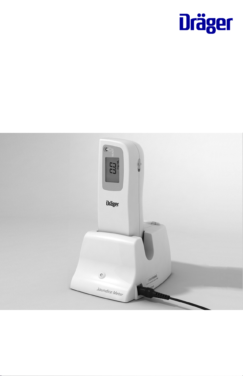
Instructions for Use
Dräger Jaundice Meter
WARNING
To properly use this medical
device, the user must obtain a
full understanding of the performance characteristics of
this medical device prior to
use by carefully reading these
Instructions for Use.
Model JM-103
Page 2

Page 3

PROPRIETARY AND CONFIDENTIAL DRAFT 9 Nov 04
Table of Contents
Section 1: Symbol Definition and Intended Use
Symbol Definition . . . . . . . . . . . . . . . . . . . . . . . . . . . . . . . . . . . 1 - 1
Intended Use . . . . . . . . . . . . . . . . . . . . . . . . . . . . . . . . . . . . . . . 1 - 4
Section 2: Introduction, Features, and Specifications
Introduction . . . . . . . . . . . . . . . . . . . . . . . . . . . . . . . . . . . . . . . .2 - 1
Measuring Point . . . . . . . . . . . . . . . . . . . . . . . . . . . . . . . . .2 - 1
Explanation of the Test . . . . . . . . . . . . . . . . . . . . . . . . . . . .2 - 2
Features. . . . . . . . . . . . . . . . . . . . . . . . . . . . . . . . . . . . . . . . . . . .2 - 6
Controls, Indicators, and Connections . . . . . . . . . . . . . . . .2 - 6
Display . . . . . . . . . . . . . . . . . . . . . . . . . . . . . . . . . . . . . . . .2 - 8
Standard Features . . . . . . . . . . . . . . . . . . . . . . . . . . . . . . . .2 - 9
Specifications . . . . . . . . . . . . . . . . . . . . . . . . . . . . . . . . . . . . . .2 - 10
Standard Features . . . . . . . . . . . . . . . . . . . . . . . . . . . . . . .2 - 10
Regulations, Standards, and Codes . . . . . . . . . . . . . . . . . .2 - 11
Device Classification. . . . . . . . . . . . . . . . . . . . . . . . . . . . .2 - 11
Electromagnetic Compatibility (EMC) Guidance and
Manufacturer’s Declarations . . . . . . . . . . . . . . . . . . . . . . .2 - 12
Section 3: Precautions and Safety Tips
Precautions . . . . . . . . . . . . . . . . . . . . . . . . . . . . . . . . . . . . . . . . .3 - 1
Electromagnetic Compatibility Precautions . . . . . . . . . . . .3 - 3
Safety Tips . . . . . . . . . . . . . . . . . . . . . . . . . . . . . . . . . . . . . . . . .3 - 4
Warning and Caution Labels . . . . . . . . . . . . . . . . . . . . . . . . . . .3 - 5
Section 4: Installation and Assembly
Installation . . . . . . . . . . . . . . . . . . . . . . . . . . . . . . . . . . . . . . . . .4 - 1
Charging the Battery . . . . . . . . . . . . . . . . . . . . . . . . . . . . . .4 - 1
Selecting the Unit of Measurement. . . . . . . . . . . . . . . . . . .4 - 3
Operational Checkout of the Jaundice Meter . . . . . . . . . . .4 - 4
Section 5: Instructions for Use
Instructions for Use . . . . . . . . . . . . . . . . . . . . . . . . . . . . . . . . . .5 - 1
Taking Measurements . . . . . . . . . . . . . . . . . . . . . . . . . . . . .5 - 1
Jaundice Meter Instructions for Use (MU01380) Page i
Page 4

Setting the Number of Average Measurements . . . . . . . . . 5 - 5
Taking Average Measurements . . . . . . . . . . . . . . . . . . . . . 5 - 6
Section 6: Cleaning, Maintenance, Replacement Parts, and Storage and
Handling
Cleaning . . . . . . . . . . . . . . . . . . . . . . . . . . . . . . . . . . . . . . . . . . 6 - 1
Steam Cleaning . . . . . . . . . . . . . . . . . . . . . . . . . . . . . . . . . 6 - 1
Cleaning Difficult to Access Areas . . . . . . . . . . . . . . . . . . 6 - 1
Disinfecting . . . . . . . . . . . . . . . . . . . . . . . . . . . . . . . . . . . . 6 - 2
Maintenance . . . . . . . . . . . . . . . . . . . . . . . . . . . . . . . . . . . . . . . 6 - 2
Calibration. . . . . . . . . . . . . . . . . . . . . . . . . . . . . . . . . . . . . .6 - 2
Replacement Parts . . . . . . . . . . . . . . . . . . . . . . . . . . . . . . . . . . . 6 - 3
Storage and Handling . . . . . . . . . . . . . . . . . . . . . . . . . . . . . . . . 6 - 4
Disposal. . . . . . . . . . . . . . . . . . . . . . . . . . . . . . . . . . . . . . . . . . . 6 - 5
Section 7: Troubleshooting
Service Calls . . . . . . . . . . . . . . . . . . . . . . . . . . . . . . . . . . . . . . . 7 - 1
Error Messages . . . . . . . . . . . . . . . . . . . . . . . . . . . . . . . . . . . . . 7 - 1
Troubleshooting . . . . . . . . . . . . . . . . . . . . . . . . . . . . . . . . . . . . 7 - 2
Appendix A: Clinical Performance Summary
Introduction . . . . . . . . . . . . . . . . . . . . . . . . . . . . . . . . . . . . . . . A - 1
Study Design . . . . . . . . . . . . . . . . . . . . . . . . . . . . . . . . . . . . . . A - 1
Performance Data. . . . . . . . . . . . . . . . . . . . . . . . . . . . . . . . . . . A - 3
Conclusion . . . . . . . . . . . . . . . . . . . . . . . . . . . . . . . . . . . . . . . A - 17
Appendix B: Doctors’ Office Data
Study Design . . . . . . . . . . . . . . . . . . . . . . . . . . . . . . . . . . . . . . B - 1
Performance Data. . . . . . . . . . . . . . . . . . . . . . . . . . . . . . . . . . . B - 3
Conclusion . . . . . . . . . . . . . . . . . . . . . . . . . . . . . . . . . . . . . . . . B - 8
Appendix C: Medical and Scientific References on Transcutaneous
Bilirubinometry
Page ii Jaundice Meter Instructions for Use (MU01380)
Page 5

DRAFT 18 May 2005
Section 1
Symbol Definition
and Intended Use
Symbol Definition
This manual contains different typefaces and icons designed to improve
readability and increase understanding of its content. Note the following
examples:
• Standard text—used for regular information.
• Boldface text—emphasizes a word or phrase.
• GMDN—Global Medical Device Nomenclature
• UMDNS—Universal Medical Device Nomenclature System
• NOTE:—sets apart special information or important instruction
clarification.
• The symbol below highlights a WARNING or CAUTION:
Warning and Caution
– A WARNING identifies situations or actions that may affect
patient or user safety. Disregarding a warning could result in
patient or user injury.
– A CAUTION points out special procedures or precautions that
personnel must follow to avoid equipment damage.
Jaundice Meter Instructions for Use (MU01380) Page 1 - 1
Page 6
DRAFT 18 May 2005
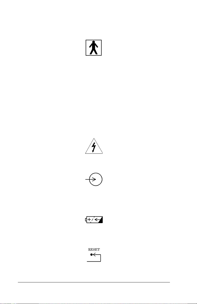
• The symbol below highlights a type BF applied part:
Type BF Applied Part
– The instrument provides a specified degree of protection
against electric shock, particularly the leakage current and
reliability of the protective ground connection with an F-type
applied part. An F-type applied part indicates an applied part
isolated from all other parts of the instrument to such a degree
that the patient leakage current allowable in a single-fault
condition is not exceeded when a voltage equal to 1.1 times the
highest-rated mains voltage is applied between the applied part
and ground.
• The symbol below highlights an ELECTRICAL SHOCK HAZARD
WARNING:
Electrical Shock Hazard Warning
• The symbol below indicates INPUT RATING:
Input Rating Symbol
• The symbol below indicates that the product uses a
RECHARGEABLE BATTERY:
Rechargeable Battery Symbol
• The symbol below indicates RESET:
RESET Button Symbol
Page 1 - 2 Jaundice Meter Instructions for Use (MU01380)
Page 7
DRAFT 18 May 2005
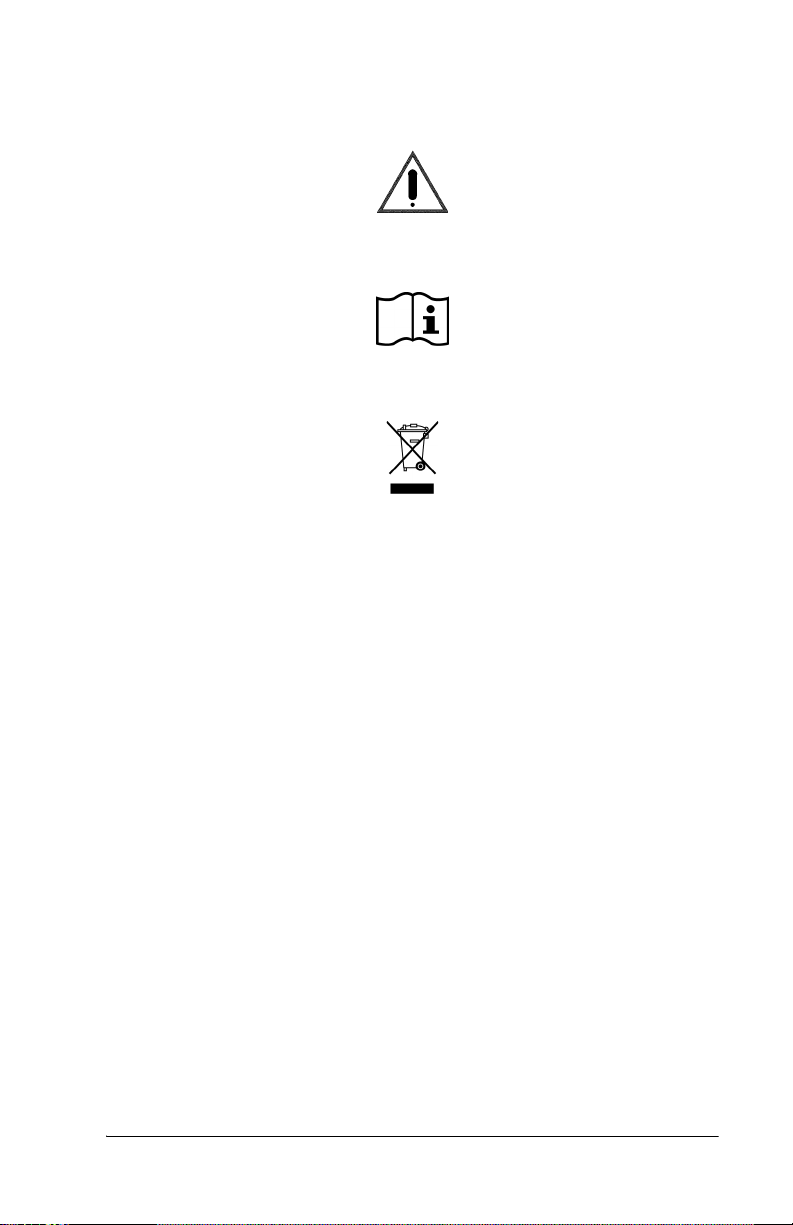
• The symbol below, when applied to the device, indicates:
ATTENTION: Consult Accompanying Documents
• The symbol below, when applied to the device, indicates:
ATTENTION: Consult Instructions for Use
• The symbol below, when applied to the device, indicates:
Do Not Throw Away
Jaundice Meter Instructions for Use (MU01380) Page 1 - 3
Page 8

DRAFT 18 May 2005
Intended Use
WARNING:
Magnetic Resonance Imaging (MRI) procedures interfere with
Jaundice Meter operation. Inaccurate readings could occur.
WARNING:
Do not use a mobile telephone when using the Jaundice Meter. A
measurement error could occur.
Intended Use of the Jaundice Meter
The Jaundice Meter is a non-invasive transcutaneous bilirubinometer. It
measures yellowness of subcutaneous tissue in newborn infants. The
unit provides a visual digital measurement that has been shown to
correlate with serum bilirubin in newborn infants.
The device is intended for use in hospitals or doctors’ offices under a
physician’s supervision or at their direction to assist clinicians in
monitoring of newborn infants. The device is not intended as a standalone screening device for diagnosis of hyperbilirubinemia. It is to be
used as a screening device in conjunction with other clinical signs and
laboratory measurements.
Newborn infants whose Jaundice Meter test results are indicative of
hyperbilirubinemia should be evaluated by their physician(s) for
appropriate patient management. Specific neonatal patient bilirubin
levels should be confirmed by other methods, such as serum bilirubin,
prior to treatment determinations.
The Jaundice Meter is not intended for home use.
Limitations (Doctors’ Office Use)
Use only on infants up to 14 days of age.
For doctors’ office application, use only the sternum location when
taking measurements.
Please be aware, performance in doctors’ offices may vary from
performance in hospitals.
Page 1 - 4 Jaundice Meter Instructions for Use (MU01380)
Page 9

DRAFT 18 May 2005
Precocious Jaundice
Do not use this device on infants with precocious jaundice. If there is a
possibility that the infant is suffering from precocious jaundice, as a
result of an incompatible blood type or hemolytic jaundice, it is
recommended that the total serum bilirubin be measured.
Intended Use of the User Manual
This manual provides instructions for installation, use, operator
maintenance, and troubleshooting of the Jaundice Meter. Draeger
Medical cannot be responsible for the performance of the Jaundice
Meter if the user does not operate the unit in accordance with the
instructions, fails to follow maintenance recommendations, or makes
any repairs with unauthorized components. Only qualified service
personnel should perform repair.
Jaundice Meter Instructions for Use (MU01380) Page 1 - 5
Page 10

DRAFT 18 May 2005
Page intentionally left blank.
Page 1 - 6 Jaundice Meter Instructions for Use (MU01380)
Page 11

DRAFT 20 June 2005
Section 2
Introduction, Features,
and Specifications
Introduction
To prevent kernicterus in newborn infants, it is very important to detect
jaundice in its early stages. The Jaundice Meter is a non-invasive
transcutaneous bilirubinometer. This hand-held device allows a quick,
non-invasive estimate of bilirubin concentration, to be used as an aid for
the management of jaundice in newborn infants. The measurements are
taken automatically when placing the instrument’s measuring probe
against the measuring site of the infant and pressing it gently; the
measured value is then displayed.
Measuring Point
Measurements must be taken only on the infant’s sternum (at hospital
sites or physicians’ offices) or forehead (at hospital sites only) where a
sufficient amount of blood is circulated. A possibility exists that the
bilirubin in the subcutaneous tissue may measure low for areas with
minimal blood flow or areas in which the subcutaneous tissue is subject
to keratinization.
Although correlation with serum bilirubin was observed for both
sternum and forehead measurements, the clinical studies performed with
the Jaundice Meter and referenced in Appendices A and B show
consistently better results with measurements taken at the sternum
versus the forehead. There is a possibility that this difference may be
more pronounced for infants that have been exposed to sunlight, such as
infants seen at doctors’ offices. Only sternum measurements were
evaluated during the studies conducted at doctors’ offices; correlation of
forehead measurements with serum bilirubin has not been evaluated,
and the device is not intended for forehead measurements at doctors’
offices.
NOTE:
Use the sternum location when taking measurements at doctors’ offices.
SPECIFICATIONS
Jaundice Meter Instructions for Use (MU01380) Page 2 - 1
Page 12
DRAFT 20 June 2005
Phototherapy
WARNING:
Do not use the Jaundice Meter after initiation of phototherapy or
after an exchange transfusion. Results may be inaccurate under
these conditions.
Explanation of the Test
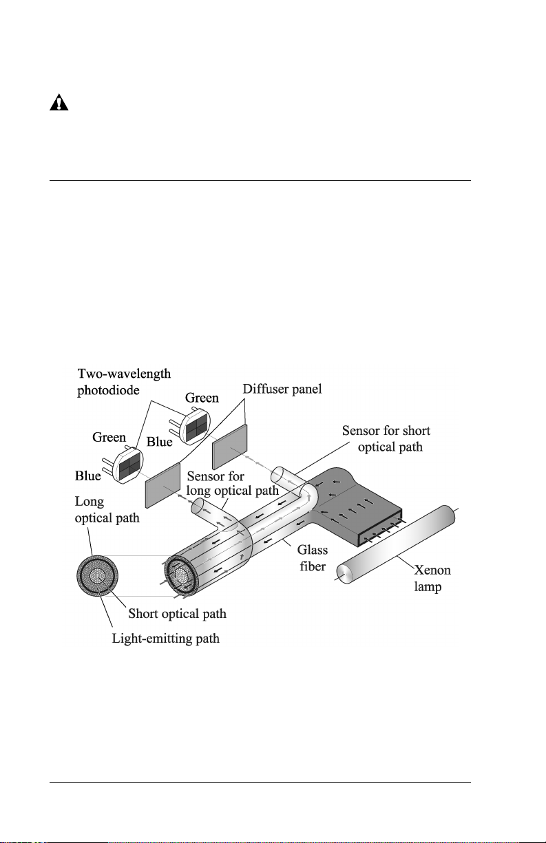
Measuring Principle
The Jaundice Meter determines the yellowness of an infant’s
subcutaneous tissue by measuring the difference in the optical densities
for light in the blue (450 nm) and green (550 nm) wavelength regions.
The measuring probe has two optical paths. This method allows for a
more precise measurement of yellowness in an infant’s subcutaneous
tissue by minimizing the influences of the melanin pigment and the skin
maturity.
When the measuring probe is pressed against the sternum or forehead of
the infant, the built-in xenon lamp flashes. The light from the xenon
lamp passes through the glass fiber and illuminates the skin. The light
scatters and is absorbed in the skin and subcutaneous tissue repeatedly,
and then finally returns to the sensor side of the glass fiber. Of the light
that returns, the part scattered from the shallow areas of the
Page 2 - 2 Jaundice Meter Instructions for Use (MU01380)
Page 13
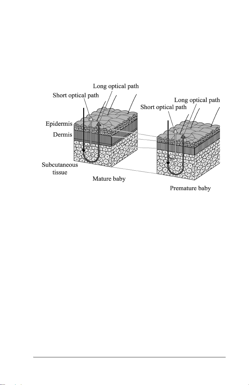
DRAFT 20 June 2005
subcutaneous tissue passes through the inner core, or short-optical path,
of the fiber. The part scattered from the deep areas of the subcutaneous
tissue passes through the outer core, or long-optical path, and then
reaches its corresponding photodiode.
SPECIFICATIONS
By calculating the difference in the optical densities, the parts that are
common to the epidermis and dermis are deducted, and as a result, the
difference in the optical densities between the two wavelength regions
can be obtained for the subcutaneous tissue only. Since the optical
density difference shows a linear correlation with the total serum
bilirubin concentration, it is converted to the estimated bilirubin
concentration and is indicated digitally.
The Jaundice Meter device software uses a correlation coefficient to
convert the measurement difference from the dual optical path to an
estimated bilirubin concentration. The calculation formula used includes
the correlation coefficients α and γ. These coefficients were determined
in pre-clinical testing. The equation used is as follows:
J
= α(L-S) + γ
sample
Where L and S are the long and short optical path measurements.
Jaundice Meter Instructions for Use (MU01380) Page 2 - 3
Page 14

DRAFT 20 June 2005
Use of the Device
Patient Population
The Jaundice Meter is indicated for use in neonatal patients born >35
weeks gestation who have not undergone transfusion or phototherapy
treatment.
Averaging of Measurements
Averaging measurements may allow for more precise results. Averaging
three or more readings, computed automatically by the Jaundice Meter
when the desired number of measurements is set (see “Setting the
Number of Average Measurements” on page 5-5), provides more
precise transcutaneous bilirubin measurements than using a single
measurement. Assess the advantages of using average measurements at
your facility. The mean of three measurements showed the highest
degree of correlation (r=0.965); however, the difference compared to a
single measurement was minimal with a single measurement (r=0.963).
Each facility should consider the advantages of averaging multiple
measurements versus using single measurements.
Averaging was not evaluated in the doctors’ office study.
Action Levels
Action levels are Jaundice Meter readings when the nurse must take
some type of action, as determined by individual facility policy, for
example: reporting results immediately to the physician, or obtaining a
serum total serum bilirubin. A facility’s action level may be determined
by the performance of the device in their unique population, which
depends on factors such as skin color, skin thickness, infant age, and
measuring site. The bias relative to serum bilirubin differs between
hospital versus physicians’ office sites (see Appendices A and B).
Different action levels may be appropriate for hospital versus
physicians’ offices.
NOTE:
Using proper action levels avoids false negatives - where an infant is
believed not to have significant jaundice but does, in fact, have
significant jaundice that might require treatment.
Calibration
The JM-103 does not require user calibration. The system includes a
checker that measures the intensity of light from the device to ensure the
light output is acceptable for proper use. Light intensity must be
checked daily.
Page 2 - 4 Jaundice Meter Instructions for Use (MU01380)
Page 15

DRAFT 20 June 2005
Processing of Measured Values
The Jaundice Meter determines the yellowness of the subcutaneous
tissue by measuring the difference in the optical densities for light in the
blue and green wavelength regions. The optical density difference has
been shown to have a linear correlation with serum bilirubin
concentration. The device computes an estimated bilirubin
concentration based on this linear correlation and provides the value on
the display.
SPECIFICATIONS
Jaundice Meter Instructions for Use (MU01380) Page 2 - 5
Page 16
DRAFT 20 June 2005
Features
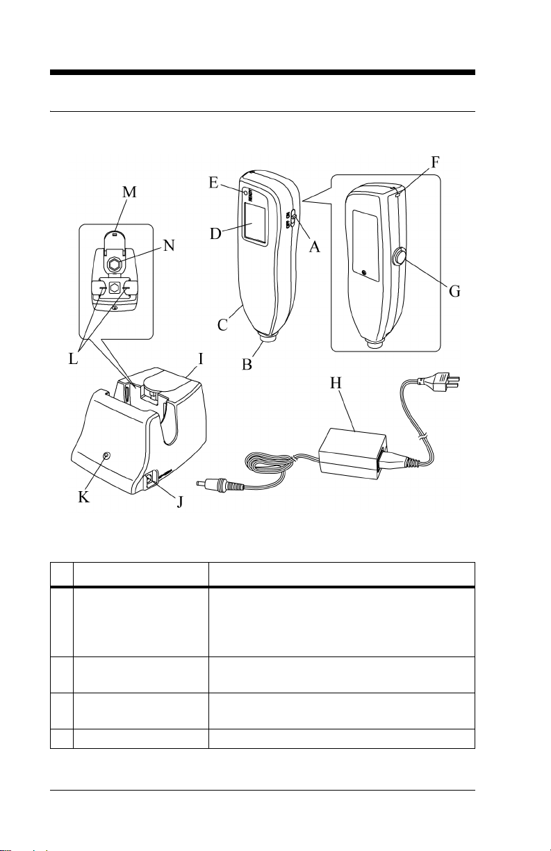
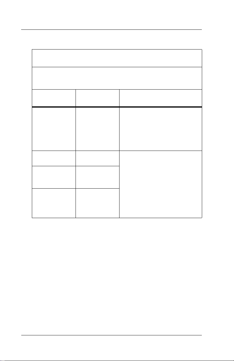
Controls, Indicators, and Connections
Controls, Indicators, and Connections
Name Function
A Power switch Turns the Jaundice Meter on and off.
When used with the Reset button, the device
switches to Check Mode and changes the unit
of measurement.
B Measuring probe Takes the measurement when pressed against
the measuring point.
C Charger section Connects the charger unit to the charger sec-
tion.
D Display Displays the measured value.
Page 2 - 6 Jaundice Meter Instructions for Use (MU01380)
Page 17
DRAFT 20 June 2005
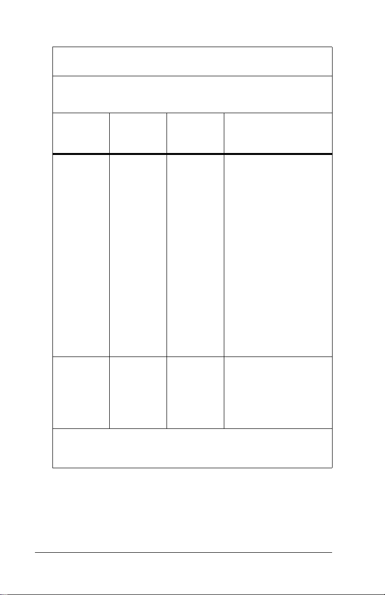
Name Function
E Ready lamp Illuminates to indicate that the Jaundice Meter
is ready for the next measurement.
F Strap attachment area Is where the strap attaches.
G Reset button Deletes the currently displayed measured
value and prepares for the next measurement.
When used with the Power switch, the device
switches to Check Mode and changes the unit
of measurement.
H DC plug Connects the charger’s DC jack to the unit.
NOTE:
Choose the appropriate power cord
adapter for country of use.
I Checker cover Covers the checker. Open this checker cover
to check the Jaundice Meter.
J DC jack Connects the AC adapter to the charger.
K Charger lamp Illuminates to indicate that the Jaundice Meter
is charging.
L Charger jack Connects the main body to the charger.
M Standard checker
values
N Checker Checks for the intensity of light output by tak-
For reference.
ing measurements in Check Mode.
SPECIFICATIONS
Jaundice Meter Instructions for Use (MU01380) Page 2 - 7
Page 18
DRAFT 20 June 2005
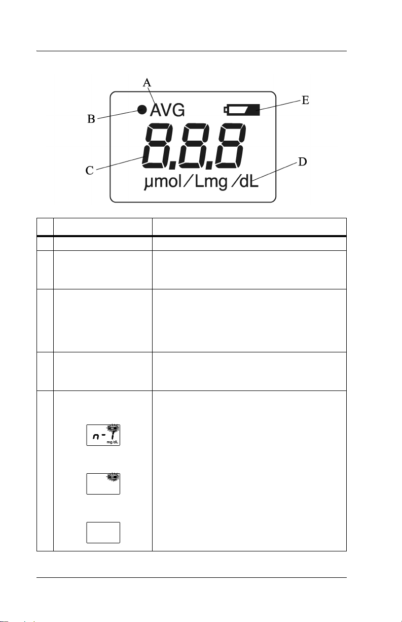
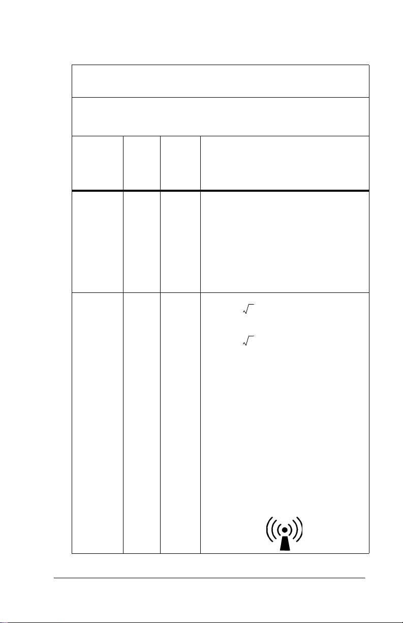
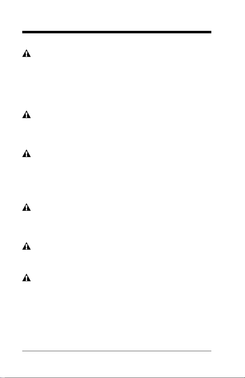
Display
Name Function
A AVG Illuminates during averaging measurement.
B Optical path indicator
(•)
C Value Displays the measured value.
D Unit of measurement Displays the unit of measurement in either
E Battery indicator When the battery power is low, the battery
When verifying light output with the checker,
(•)illuminates when the L-value appears and
extinguishes when the S-value appears.
NOTE: When the measured value is greater
than 20 mg/dl or 340 μmol/L, the display
shows “---” and the physician should be contacted.
milligrams per deciliter (mg/dL) or micromoles of solute per liter (μmol/L)
indicator blinks. Charge the battery as soon as
possible (see “Charging the Battery” on page
4-1).
If only the battery indicator illuminates, the
battery has run out. Go to “Charging the Battery” on page 4-1.
If the power is on and the display is blank, the
battery is completely exhausted. Go to
“Charging the Battery” on page 4-1.
Page 2 - 8 Jaundice Meter Instructions for Use (MU01380)
Page 19

Standard Features
• Jaundice Meter (JM-103)
DRAFT 20 June 2005
• Charger unit (Model JM-A30) with a checker
• AC adapter (Model JM-A32)
• Carrying case and wrist strap
• Power cable adapter set
SPECIFICATIONS
Jaundice Meter Instructions for Use (MU01380) Page 2 - 9
Page 20

DRAFT 20 June 2005
Specifications
Standard Features
Feature Dimension
Model name JM-103
Measuring method Determines the yellowness of the
subcutaneous tissue by using two
optical paths to measure the optical
density difference at two wavelengths
Measurement range 0.0 mg/dL to 20 mg/dL or 0 μmol/L
to 340 μmol/L
Clinical Data Standard Error of
Estimate (SEE) *
Light source Pulse xenon arc lamp
Light source life 150000 measurements
Detectors Silicon photodiodes
Power source 2.4 V, Special Ni-MH battery
Protection type and level Internally-powered instrument, BF-
Minimum number of
measurements when fully charged
Operating temperature range 10°C (50°F) to 40°C (104°F)
Operating relative humidity range 30% to 95% non-condensing
Storage temperature range -10°C (14°F) to 50°C (122°F)
Storage relative humidity range 30% to 95% non-condensing
Dimensions 4.8 cm (1.9") wide x 15.4 cm (6.0")
Weight, including Ni-MH battery 150 g (5.3 oz)
AC adapter input 100V - 240V 50/60Hz, 11-18VA
± 1.5 mg/dL or ± 25.5 μmol/L
type
400 single measurements
high x 3.2 cm (1.2") deep
*The standard deviation shown above is based on the average of the
clinical data available. On average, 66% of results fall within this range,
and the remainder fall outside this range. This value can be affected by
variables such as age, skin color, and preformance of the device in the
hands of the user. Refer to Appendixes A and B for a detailed
description of results by clinical site, measurement location, and patient
demographics. The SEE shown in the table are based on the clinical data
Page 2 - 10 Jaundice Meter Instructions for Use (MU01380)
Page 21

DRAFT 20 June 2005
available and can be affected by variables such as infant developmental
age, ethnicity, etc. Therefore, we recommend that the JM-103 be used in
conjunction with other clinical signs and laboratory measurements.
"Specific Bilirubin Measurement" should be confirmed by other
methods such as laboratory blood serum analysis.
Regulations, Standards, and Codes
In North America, with respect to electrical shock, fire, and mechanical
hazards only, this instrument complies with UL 60601-1 and CAN/CSA
C22.2 No. 601.1.
In Europe, this instrument complies with EN60601-1, EN60601-1-2,
and EN ISO13485, and EN ISO14971.
Directive 2002/96/EC of the European Parliament and of the Council of
2003-01-27 on Waste Electrical and Electronic Equipment (WEEE)
Annex IV, prEN 50419 applies.
Device Classification
The Jaundice Meter (JM-103) meets the requirements for the following
classifications:
• Protection against electrical shock: Internally powered
• Type of applied part: BF
• IPX0—ordinary equipment (Degree of protection against harmful
ingress of water: Not applicable.)
SPECIFICATIONS
• Not suitable for use in the presence of flammable anesthetic mixture
with air or oxygen or nitrous oxide.
• Mode of operation of equipment: Continuous while in use (IEC
60601-1)
• Classification in accordance with EU Directive 93/42/EEC: IIa
• UMDNS code/GMDN code: 16-166/35475
Jaundice Meter Instructions for Use (MU01380) Page 2 - 11
Page 22
DRAFT 20 June 2005
Electromagnetic Compatibility (EMC) Guidance and
Manufacturer’s Declarations
Guidance and Manufacturer’s Declaration—Electromagnetic
Emissions
The Jaundice Meter is intended for use in the electromagnetic environments specified below. The customer or user of the unit should
ensure that the unit is used in such environments.
Emissions Test Compliance
Radio frequency
(RF) emissions
—CISPR 11
RF emissions—
CISPR 11
Harmonic Emissions—IEC
61000-3-2
Voltage fluctuations/ flicker
emissions—IEC
61000-3-3
Group 1 The Jaundice Meter uses RF
Class B The Jaundice Meter is suitable
Class A
Complies
Electromagnetic
Environment—Guidance
energy only for its internal function. Therefore, its RF emissions are very low and are not
likely to cause interference with
nearby electronic equipment.
for use in all establishments,
including domestic and those
directly connected to the public
low-voltage power supply network that supplies buildings
used for domestic purposes.
Page 2 - 12 Jaundice Meter Instructions for Use (MU01380)
Page 23

DRAFT 20 June 2005
Guidance and Manufacturer’s Declaration—Electromagnetic
Immunity
The Jaundice Meter is intended for use in the electromagnetic environments specified below. The customer or user of the unit should
ensure that the unit is used in such environments.
Immunity
Test
Electrostatic
discharge
(ESD)—
IEC 610004-2
Electrical
fast transient/burst
—IEC
61000-4-4
Surge—IEC
61000-4-5
IEC 60601
Test Level
± 6 kV contact
± 8 kV air
± 2 kV for
power supply lines
± 1 kV
differential
mode
Compliance
Level
± 6 kV contact
± 8 kV air
± 2 kV for
power supply lines
± 1 kV
differential
mode
Electromagnetic
Environment—
Guidance
The floors should be
wood, concrete, or
ceramic tile. If floors are
covered with synthetic
material, the relative
humidity should be at
least 30%.
Mains power quality
should be that of a typical
commercial or hospital
environment.
Mains power quality
should be that of a typical
commercial or hospital
environment.
SPECIFICATIONS
Jaundice Meter Instructions for Use (MU01380) Page 2 - 13
Page 24
DRAFT 20 June 2005
Guidance and Manufacturer’s Declaration—Electromagnetic
Immunity
The Jaundice Meter is intended for use in the electromagnetic environments specified below. The customer or user of the unit should
ensure that the unit is used in such environments.
Immunity
Test
Voltage
dips, short
interruptions, and
voltage variations on
power supply input
lines—IEC
61000-4-11
Power frequency
(50/60 Hz)
magnetic
field—IEC
61000-4-8
IEC 60601
Test L e v e l
< 5% U
95% dip in
U
) for 0.5
T
cycles
40% U
(60% dip in
U
) for 5
T
cycles
70% U
(30% dip in
U
) for 25
T
cycles
< 5% U
95% dip in
) for 5
U
T
seconds
(>
T
T
T
(>
T
Compliance
Level
< 5% U
T
(>
95% dip in
U
) for 0.5
T
cycles
40% U
T
(60% dip in
U
) for 5
T
cycles
70% U
T
(30% dip in
U
) for 25
T
cycles
< 5% U
T
(>
95% dip in
) for 5
U
T
seconds
3 A/m 3 A/m The power frequency
Electromagnetic
Environment—
Guidance
Mains power quality
should be that of a typical
commercial or hospital
environment. If the user
of the unit requires continued operation during
power mains interruptions, it is recommended
that the unit be powered
from an uninterruptable
power supply or battery.
magnetic fields should be
at levels characteristic of
a typical location in a typical commercial or hospital environment.
NOTE:
U
is the AC mains voltage prior to the application of the test
T
level.
Page 2 - 14 Jaundice Meter Instructions for Use (MU01380)
Page 25
DRAFT 20 June 2005
Guidance and Manufacturer’s Declaration—Electromagnetic
Immunity
The Jaundice Meter is intended for use in the electromagnetic environments specified below. The customer or user of the unit should ensure
that the unit is used in such environments.
Immunity
Test
Conducted
RF—IEC
61000-4-6
Radiated
RF—IEC
61000-4-3
IEC
60601
Test
Level
3 Vrms
150
kHz to
80
MHz
3 V/m 3 V/m
80
MHz
to 2.5
GHz
Compli
ance
Level
Electromagnetic Environment—
Guidance
Recommended Separation Distance
3 Vrms Portable and mobile RF communica-
tion equipment should be used no
closer to any part of the Jaundice
Meter, including cables, than the recommended separation distance calculated from the equation applicable to
the frequency of the transmitter.
Recommended Separation Distance
d 1.2 P=
d 2.3 P=
80 MHz to 800 MHz
800 MHz to 2.5 GHz
where P is the maximum output power
rating of the transmitter in watts (W)
according to the transmitter manufacturer and d is the recommended separation distance in meters (m).
Field strengths from fixed RF transmitters, as determined by an electromag-
netic site survey
the compliance level in each frequency
b
range.
a
, should be less than
Interference may occur in the vicinity
of equipment marked with the following symbol:
SPECIFICATIONS
Jaundice Meter Instructions for Use (MU01380) Page 2 - 15
Page 26

DRAFT 20 June 2005
Guidance and Manufacturer’s Declaration—Electromagnetic
Immunity
The Jaundice Meter is intended for use in the electromagnetic environments specified below. The customer or user of the unit should ensure
that the unit is used in such environments.
IEC
Immunity
Test
60601
Test
Level
NOTE:
At 80 MHz and 800 MHz, the higher frequency range applies.
NOTE:
These guidelines may not apply in all situations. Electromagnetic
propagation is affected by absorption and reflection from
structures, objects, and people.
a. Field strengths from fixed transmitters, such as base stations for radio,
cellular/cordless telephones, land-mobile radios, amateur radio, AM and FM
radio broadcast, and TV broadcast cannot be predicted theoretically with
accuracy. To assess the electromagnetic environment due to fixed-RF
transmitters, an electromagnetic site survey should be considered. If the
measured field strength in the location in which the unit is used exceeds the
applicable RF compliance level, observe the unit to verify normal operation.
If abnormal performance is observed, additional measures may be necessary,
such as reorienting or relocating the unit.
b. Over the frequency range 150 kHz to 80 MHz, field strengths should be < 3
V/m.
Compli
ance
Level
Electromagnetic Environment—
Guidance
Recommended Separation Distance
Page 2 - 16 Jaundice Meter Instructions for Use (MU01380)
Page 27
DRAFT 18 May 2005
Section 3
Precautions and Safety Tips
Precautions
WARNING:
Do not use the instrument in areas where flammable or
combustible gases, such as anesthetic gases, are present. Doing
so could result in a fire. Personal injury or equipment damage
could occur.
WARNING:
If the instrument, the charger unit, or the AC adapter are
damaged, or if smoke or an odd smell occurs, do not use the
instrument, the charger unit, or the AC adapter. In such situations,
immediately turn off the instrument, unplug the AC adapter from
its power source, and contact the nearest authorized service
facility. Failure to do so could result in fire, personal injury, or
equipment damage.
WARNING:
Do not use the Jaundice Meter after initiation of phototherapy or
after an exchange transfusion, because results may be
inaccurate under these conditions. Patient injury could occur.
SHOCK HAZARD:
Always plug the instrument into an AC outlet of the correctly rated
voltage and frequency. Failure to do so could result in fire,
personal injury, or equipment damage.
SHOCK HAZARD:
Do not disassemble or modify the instrument, the charger unit, or
the AC adapter. Fire, personal injury, or equipment damage could
occur.
CAUTION:
Do not place the instrument on an unstable or sloping surface.
The instrument or charger unit could drop or overturn. Equipment
damage could occur.
Jaundice Meter Instructions for Use (MU01380) Page 3 - 1
Page 28
DRAFT 18 May 2005
CAUTION:
Do not use the instrument in direct sunlight. Equipment damage
could occur.
CAUTION:
The Jaundice Meter is a precision instrument. When using it, do
not drop it, expose it to shocks or strong vibrations, or place
heavy objects on it. Equipment damage could occur.
CAUTION:
Do not allow blood or other liquids to come in contact with the
instrument. Should blood or other liquids come in contact with the
instrument, immediately clean the instrument (see “Cleaning” on
page 6-1). Failure to do so could result in equipment damage.
CAUTION:
The instrument has a built-in, non-user-replaceable battery. Do
not disassemble the instrument to replace the battery. To replace
the battery, contact your dealer or authorized service center.
Failure to do so could result in equipment damage.
CAUTION:
Federal law restricts this device to sale by or on the order of a
physician.
Page 3 - 2 Jaundice Meter Instructions for Use (MU01380)
Page 29
DRAFT 18 May 2005
Electromagnetic Compatibility Precautions
General information on electromagnetic compatibility (EMC)
according to the international EMC standard IEC 60601-12: 2001
Pins of connectors identified with the ESD warning
symbol shall not be touched and not be connected
unless ESD precautionary procedures are used. Such
precautionary procedures may include antistatic
clothing and shoes, the touch of a ground stud before
and during connecting the pins or the use of electrically
isolating and antistatic gloves. All staff involved in the
above shall receive instruction in these procedures.
NOTE:
Portable and mobile RF communications equipment can affect medical
electrical equipment.
NOTE:
Medical electrical equipment needs special precautions regarding
electromagnetic compatibility (EMC) and needs to be installed and put
into service according to the EMC information provided in the technical
documentation available from Dräger Service upon request.
Jaundice Meter Instructions for Use (MU01380) Page 3 - 3
Page 30
DRAFT 18 May 2005
Safety Tips
WARNING:
This instrument emits intense light to take its measurements.
Take measurements only at the sterum (preferred) or forehead
(hospital only). Doctors’ office use should be performed at the
sternum only. Do not press the measuring probe when it is
directed toward the infant’s or caregiver’s eyes. Damage to the
eyes could occur.
WARNING:
Before use, clean the measuring probe by wiping it with an
alcohol swab. Failure to do so could result in the spread of
infection or infant injury.
WARNING:
The charger unit (JM-A30) and the AC adapter (JM-A32) are
solely designed for use with the Jaundice Meter (JM-103). Use
them only when charging the instrument. Using them to charge
other equipment could result in personal injury or equipment
damage.
WARNING:
Only properly trained personnel should troubleshoot the Jaundice
Meter. Troubleshooting by unauthorized personnel could result in
personal injury or equipment damage.
WARNING:
Follow the product manufacturer’s instructions. Failure to do so
could result in personal injury or equipment damage.
WARNING:
This product has been validated with the accessories and options
listed in this manual and found to comply with all relevant safety
and performance requirements applicable to the device. It is
therefore the responsibility of that person or organization who
makes an unauthorized modification, or incorporates an
unapproved attachment to the device, to ensure that the system
still complies with those requirements. [IHA036]
Page 3 - 4 Jaundice Meter Instructions for Use (MU01380)
Page 31

DRAFT 18 May 2005
SHOCK HAZARD:
Do not plug or unplug the AC power cord’s plug with wet hands.
Personal injury or equipment damage could occur.
SHOCK HAZARD:
Before cleaning, maintenance, or parts replacement, unplug the
charger unit from its power source. Failure to do so could result in
personal injury or equipment damage.
SHOCK HAZARD:
Do not expose the unit to excessive moisture that would allow for
liquid pooling. Personal injury or equipment damage could occur.
CAUTION:
Do not use harsh cleansers/detergents, such as scouring pads
and heavy duty grease removers, or solvents, such as toluene,
xylene, and acetone. Equipment damage could occur.
Warning and Caution Labels
Jaundice Meter Instructions for Use (MU01380) Page 3 - 5
Page 32

DRAFT 18 May 2005
Page intentionally left blank.
Page 3 - 6 Jaundice Meter Instructions for Use (MU01380)
Page 33

DRAFT 20 June 2005
Section 4
Installation and Assembly
Installation
Before using the instrument, charge and inspect the instrument.
Charging the Battery
When using the instrument for the first time, ensure that it is fully
charged. To maintain a full charge at all times, place the instrument on
the charger unit when it is not being used for measurements. When the
battery power is low, the Battery display blinks.
If the Jaundice Meter is left uncharged for a long period of time, the
power of the battery diminishes; ensure that it is charged prior to use. To
charge the Jaundice Meter, perform the following:
WARNING:
The charger unit (Model JM-A30) and the AC adapter (Model JMA32) are solely designed for use with the Jaundice Meter (JM-
103). Use them only when charging the instrument. Using them
to charge other equipment could result in personal injury or
equipment damage.
1. Plug the AC adapter into the DC jack
of the charger unit. Use only the
charger unit and AC adapter supplied
with the Jaundice Meter.
SHOCK HAZARD:
Do not plug or unplug the AC power
cord’s plug with wet hands. Personal
injury or equipment damage could
occur.
2. Choosing the appropriate power cord
adapter for the country of use, plug the
AC adapter’s plug into an AC outlet.
Never do so with wet hands.
Jaundice Meter Instructions for Use (MU01380) Page 4 - 1
Page 34

DRAFT 20 June 2005
CAUTION:
Unit must be placed in charger as shown, or damage to charging
contacts could occur.
3. Place the Jaundice Meter on the
charger unit so that its display faces
you. When the Jaundice Meter is set
on the charger unit properly, the
Charger lamp lights up.
NOTE:
With a fully charged battery, approximately
400 measurements can be taken.
4. Allow approximately 32 hours for
charging to complete.
CAUTION:
The instrument has a built-in, non-user-replaceable battery. Do
not disassemble the instrument to replace the battery. To replace
the battery, contact your dealer or authorized service center.
Failure to do so could result in equipment damage.
5. To replace the battery, contact your dealer or an authorized service
facility.
Page 4 - 2 Jaundice Meter Instructions for Use (MU01380)
Page 35

DRAFT 20 June 2005
Selecting the Unit of Measurement
1. Hold down the Reset button, and turn
on the Power switch. Do not release
the Reset button.
2. While continuing to press the Reset
button, allow approximately 15
seconds for the unit of measurement to
switch from mg/dL to μmol/L, or vice
versa.
3. Ensure that the unit’s display has
changed.
4. Release the Reset button when unit
displays an appropriate unit of
measurement. The Ready lamp
illuminates, indicating that the
instrument is ready to take a
measurement.
5. To change the unit of measurement
once more, turn off the Power switch,
and repeat step 1.
Jaundice Meter Instructions for Use (MU01380) Page 4 - 3
Page 36

DRAFT 20 June 2005
Operational Checkout of the Jaundice Meter
Do not touch the surface of the checker (located in the charging base)
with your fingers. If the checker gets dirty, wipe it with a soft cloth
dampened with alcohol, and then wipe it with a dry cloth. Although the
JM-103 device can be damaged as stated on pages 3-1 and 3-4, we
recommend the unit always be verified to be operating properly by
following the steps as stated in sections 4 and 5. Always remove the unit
from service if there are concerns regarding the unit’s performance, and
immediately contact your Dräger Medical representative.
For quality control purposes, periodically compare the JM-103 to serum
bilirubin results. This checks that the instrument maintains consistent
performance over time and that the operators are using the instrument
properly.
Using the checker supplied with the charger unit, check the instrument
to verify that the meter light output is within range for both long and
short wavelengths of light. The labeling on the inside cover of the
checker will state the acceptance ranges for both long and short
wavelengths. The procedure to verify is as follows:
1. Hold the Reset button down, and set
the Power switch to the On position.
NOTE:
If the Reset button is held down for longer
than 15 seconds, the unit of measurement
switches.
2. After CHE appears on the display
window, immediately release the
Reset button. If the Reset button is
held down for longer than 15 seconds,
switch the unit of measurement back to
its previous setting (see “Selecting the
Unit of Measurement” on page 4-3).
3. Visually confirm that CHE appears in
the display and that the Ready lamp
illuminates.
Page 4 - 4 Jaundice Meter Instructions for Use (MU01380)
Page 37

DRAFT 20 June 2005
4. Open the cover of the checker. Use
only the checker supplied with the
Jaundice Meter.
5. Place the measuring probe
perpendicular to the checker, and push
down gently until the unit clicks.
6. If the measuring probe contacts the
checker at an angle, place it
perpendicular, and take the
measurement again.
NOTE:
The display interchanges between the Lvalue, the measured value of the longoptical path, and the S-value, the measured
value of the short-optical path. When the Lvalue is displayed, “•” appears in the upper
left-hand corner of the display.
7. Confirm the measured value. If both
the L-value and the S-value are within
± 1.0 of the reference values indicated
on the checker cover, the unit is
acceptable for use.
8. If the measured value exceeds ± 1.0 of
the reference value, perform the
following:
Jaundice Meter Instructions for Use (MU01380) Page 4 - 5
Page 38

DRAFT 20 June 2005
a. Clean both the checker and the measuring probe.
b. Place the measuring probe perpendicular to the checker, and
push down gently until a click sounds.
c. If the measured value still exceeds ± 1.0 of the reference value,
contact the nearest authorized service facility, and take the unit
out of service.
9. Close the cover of the checker.
10. Set the Power switch to the Off position.
Page 4 - 6 Jaundice Meter Instructions for Use (MU01380)
Page 39

DRAFT 20 June 2005
Section 5
Instructions for Use
Instructions for Use
WARNING:
The JM-103 is a screening device for bilirubin in the tissues and is
not intended to be used as a stand-alone measurement. When
Jaundice Meter results meet or exceed action levels established
by the unit, department, or facility, or are excessive for the
newborn's age in hours, the user should follow the procedures
established by the user's facility.
WARNING:
If the caregiver has any concerns regarding the values presented
by the JM-103 for bilirubin concentration, the physician should be
notified immediately for a determination whether supportive
laboratory blood serum analysis is required or infant retest is
appropriate.
Taking Measurements
CAUTION:
Unit must be placed in charger as
shown, or damage to charging contacts
could occur.
1. Remove the Jaundice Meter from the
charger unit.
NOTE:
Check the light output of the device at least once each shift (refer to
“Operational Checkout of the Jaundice Meter” on page 4-4). Proper
light output is one factor that affects meter performance. Light output
must be within the range shown on the inside cover of the checker to
obtain reliable measurements.
Jaundice Meter Instructions for Use (MU01380) Page 5 - 1
Page 40

DRAFT 20 June 2005
WARNING:
Before use, clean the measuring probe
by wiping it with an alcohol swab. Failure
to do so could result in the spread of
infection or infant injury.
2. Using medicinal alcohol and a soft
cloth, clean the measuring probe.
3. Set the Power switch to the On
position. The measured value for a
single measurement, n-1, appears on the
display.
4. Ensure that the Ready lamp illuminates.
5. If the battery indicator blinks, charge the
battery (see “Charging the Battery” on
page 4-1).
Page 5 - 2 Jaundice Meter Instructions for Use (MU01380)
Page 41

DRAFT 20 June 2005
WARNING:
Do not press the measuring probe when it is directed toward the
infant’s or caregiver’s eyes. Damage to the eyes could occur.
WARNING:
Take measurements only on the infant’s sternum (at hospital sites
or physicians’ offices) or forehead (at hospital sites only).
Inaccurate readings could occur.
6. Perform the following:
a. Place the measuring probe
vertically against the infant’s
sternum (at hospital sites or
physicians’ offices) or forehead (at
hospital sites only). Avoid any
bruises or discolored areas of the
skin.
b. Push the measuring probe gently
until a click sounds. The
instrument’s xenon lamp flashes
momentarily, and the measured
value appears on the display.
Jaundice Meter Instructions for Use (MU01380) Page 5 - 3
Page 42
DRAFT 20 June 2005
c. If the measured value is outside the
measurement range of 20 mg/dL or
340 μmol/L, the display shows “---”
and the user should contact the
physician.
NOTE:
If the instrument is inactive for more than 60 seconds, the backlight on
the display goes out.
7. To take another measurement, press
the Reset button, and continue from step 4.
8. To stop measuring, perform the following:
a. Set the Power switch to the Off position.
b. Using medicinal alcohol, clean the measuring probe.
c. Place the Jaundice Meter on the charger unit. When the
Jaundice Meter is not in use, keep it in the charger unit with the
display facing forward.
Page 5 - 4 Jaundice Meter Instructions for Use (MU01380)
Page 43

DRAFT 20 June 2005
Setting the Number of Average Measurements
1. Set the Power switch to On or press
the Reset button to prepare the
instrument for measurement.
• n-1, n-2, and so on (up to n-5)
will appear.
2. Press the Reset button for 5 seconds. The number of average
measurements will switch as follows:
3. Release the Reset button when the required number of average
measurements is displayed.
•If n-2 through n-5 is selected,
AV G appears in the upper left
corner of the display.
• The selected number of average
measurements will be recorded.
Jaundice Meter Instructions for Use (MU01380) Page 5 - 5
Page 44

DRAFT 20 June 2005
Taking Average Measurements
1. Set the number of average measurements needed.
2. Ensure that the Ready lamp is
illuminated once n-5 appears.
NOTE:
n-5 is used in the steps below as an
example. The number of measurements
you require and set is the number that
should appear in the display.
NOTE:
Each measurement must be taken
individually by the user. The first measurement is complete when the
measuring probe is pressed against the patient and the unit clicks. The
probe must then be lifted from the patient and reapplied for the total
number of measurements selected (in this example, five measurements).
WARNING:
This instrument emits intense light to take its measurements.
Take measurements at the sternum or forehead in hospital
applications or at the sternum only in doctors’ office applications.
Do not press the measuring probe when it is directed toward the
infant’s or caregiver’s eyes. Damage to the eyes could occur.
NOTE:
It is recommended that all of the measurements taken for averaging be
taken from the same measuring point—sternum (at hospital sites or
physicians’ offices) or forehead (at hospital sites only).
3. Place the measuring probe vertically
on the measuring point, and then apply
gentle pressure until the probe clicks.
• The measurement will be taken,
and the number of remaining
measurements will be displayed.
Page 5 - 6 Jaundice Meter Instructions for Use (MU01380)
Page 45

DRAFT 20 June 2005
4. While ensuring that the Ready lamp is illuminated, repeat the
measuring until the number of remaining measurements is 0.
• When the remaining number of
measurements is completed, the
average of the measured values
appears in the display.
• If the instrument is left without
the preset number of
measurements taken, the setting
will be canceled without the
measurement value being
displayed. To set the average
measurements again, press the Reset button and reset the
number of average measurements needed.
• To change the number of average measurements, refer to
“Setting the Number of Average Measurements” on page 5-5.
Jaundice Meter Instructions for Use (MU01380) Page 5 - 7
Page 46

DRAFT 20 June 2005
Page intentionally left blank.
Page 5 - 8 Jaundice Meter Instructions for Use (MU01380)
Page 47

DRAFT 18 May 2005
Section 6
Cleaning, Maintenance,
Replacement Parts, and
Storage and Handling
Cleaning
SHOCK HAZARD:
Before cleaning, maintenance, or parts replacement, unplug the
charger unit from its power source. Failure to do so could result in
personal injury or equipment damage.
SHOCK HAZARD:
Do not expose the unit to excessive moisture that would allow for
liquid pooling. Personal injury or equipment damage could occur.
CAUTION:
Do not use harsh cleansers/detergents, such as scouring pads
and heavy duty grease removers, or solvents, such as toluene,
xylene, and acetone. Equipment damage could occur.
If there is no visible soilage with possible body fluids, clean the unit
with alcohol or a medical instrument detergent and warm wet cloth or
gauze sponge. If disinfection is desired, use a disinfectant as explained
in “Disinfecting” on page 6-2. Do not submerge unit in water or hold
under running water to rinse.
Steam Cleaning
Do not use any steam cleaning device on the unit. Do not autoclave the
unit. Excessive moisture can damage mechanisms or electronics in this
unit.
Cleaning Difficult to Access Areas
Do not attempt to disassemble the Jaundice Meter or base for cleaning.
Wipe exterior surfaces only. To remove difficult spots or stains, use a
soft bristle brush and alcohol or a medical instrument detergent. To
loosen heavy, dried-on soil, saturate the spot with a damp gauze sponge
or cloth. Disinfecting is preferable in cases of contamination (visible).
Jaundice Meter Instructions for Use (MU01380) Page 6 - 1
Page 48

DRAFT 18 May 2005
Disinfecting
When there is visible soilage, and between patients, disinfect the unit
with alcohol.
Maintenance
WARNING:
Only qualified service personnel should perform preventive
maintenance on the Jaundice Meter. Preventive maintenance
performed by unauthorized personnel could result in personal
injury or equipment damage.
Qualified service personnel should inspect the equipment at least
annually. Service is required only if the unit ceases to function as
intended or fails the checker reading (see “Operational Checkout of the
Jaundice Meter” on page 4-4).
NOTE:
For disposal of consumable materials, see “Disposal” on page 6-5.
Calibration
WARNING:
Only qualified service personnel should calibrate the Jaundice
Meter. Calibration performed by unauthorized personnel could
result in personal injury or equipment damage.
Qualified service personnel should calibrate the equipment at least
annually.
Page 6 - 2 Jaundice Meter Instructions for Use (MU01380)
Page 49

DRAFT 18 May 2005
Replacement Parts
CAUTION:
The instrument has a built-in, non-user-replaceable battery. Do
not disassemble the instrument to replace the battery. To replace
the battery, contact your dealer or authorized service center.
Failure to do so could result in equipment damage.
For a listing of replacement parts, single-use items, and accessories for
the operation of the Jaundice Meter, refer to Table 1 on page 6-3. Parts
other than those shown should be replaced only by qualified service
personnel.
Table 1: Replacement Parts
Part Number Description
MU20506 Dräger Jaundice Meter, model JM-103
MU00831 Battery
MU01704 Soft case
MU01705 Carrying strap
MU19527 Charger base, EN, UL
MU19528 Charger base, EN, CE
MU19625 Charger base, FR, CE
MU19627 Charger base, ES, CE
MU19628 Charger base, DE, CE
MU19629 Charger base, IT, CE
MU19630 Charger base, PT, CE
MU19631 Charger base, NL, CE
MU19632 Charger base, SV, CE
MU19633 Charger base, DA, CE
MU19634 Charger base, NO, CE
MU19635 Charger base, SK, CE
MU19636 Charger base, CS, CE
MU19637 Charger base, HU, CE
MU19638 Charger base, PL, CE
MU19791 AC adapter, 120 V, US
MU19792 AC adapter, 240 V, EU
1841793 Cable, North America, 3 m, 5-15P, 120 V
Jaundice Meter Instructions for Use (MU01380) Page 6 - 3
Page 50

DRAFT 18 May 2005
Part Number Description
1851691 Cable, CH, 3 m, SN SEV 1011
1851705 Cable, AU, 3 m, AS 3112
1851713 Cable, GB, 3 m, BS 1363
1868160 Cable, 3 m, N 5-15P 250 V
1868950 Cable, DK, 3 m
Storage and Handling
When storing the instrument, pay attention to the following conditions:
• Store the instrument at a temperature range of -10°C (14°F) to 50°C
(122°F), and at a non-condensing relative humidity range of 30% to
95%.
• Keep the instrument dry.
• Do not store the instrument in locations that may have an adverse
effect on its performance, such as:
– Direct sunlight—do not store near windows.
– Extreme dust—do not store in closets or bins where dust or lint
can gather.
– Air having salinity or sulphur content.
– Strong magnetic fields—do not store near MRI or other
imaging equipment, and do not store near operating rooms.
• Do not subject the instrument to severe vibration or impact.
• Do not store the instrument in locations where chemicals are stored
or where solvent gases may be emitted.
• To ensure no problems will exist the next time the main body and
charger are used, thoroughly clean the main body and charger with
alcohol, and store them together.
Page 6 - 4 Jaundice Meter Instructions for Use (MU01380)
Page 51

DRAFT 18 May 2005
Disposal
This device is subject to EU Directive 2002/96/EC (WEEE). It is not
registered for use in private households, and may not be disposed of at
municipal collection points for waste electrical and electronic
equipment.
Dräger Medical has authorized a firm to dispose of this device in the
proper manner. For more detailed information, please contact your local
Dräger Medical organization. (Alternatively: further information can be
obtained from our national Dräger Medical organization.)
Jaundice Meter Instructions for Use (MU01380) Page 6 - 5
Page 52

DRAFT 18 May 2005
Page intentionally left blank.
Page 6 - 6 Jaundice Meter Instructions for Use (MU01380)
Page 53

DRAFT 18 May 2005
Section 7
Troubleshooting
Service Calls
When calling technical support about your unit, be prepared to give the
serial number from the product identification label. When giving the
serial number, the technical support representative can identify your unit
and provide the information you need more quickly.
Error Messages
For warnings that may appear on the display window, refer to the table
below.
Error Messages
War ning Cause So lutio n
Er1 The measured value is
below the range of the
device. In the case of an averaging measurement, the measurement fluctuation is
excessively large.
The device is malfunctioning. Take the unit out of service,
Er2
through
Er6
A measurement error may
have occurred during an averaging measurement, or the
hardware is not functioning
properly.
Take the measurement again.
If Er1 still appears, use
another device to repeat the
measurement, or perform a
serum bilirubin test.
and contact the nearest authorized service facility.
Set the Power switch to the
Off position, and then return
it to the On position. If the
warning still appears, contact
the nearest authorized service
facility.
Jaundice Meter Instructions for Use (MU01380) Page 7 - 1
Page 54

DRAFT 18 May 2005
Troubleshooting
WARNING:
Only properly trained personnel should troubleshoot the Jaundice
Meter. Troubleshooting by unauthorized personnel could result in
personal injury or equipment damage.
If an abnormality occurs with the Jaundice Meter, perform the
following:
1. Refer to the table below, and take the necessary action given.
2. If the abnormality still appears, set the Power switch to the Off
position, and then return it to the On position.
3. If the abnormality still continues, contact the nearest authorized
service facility, and take the unit out of service.
Page 7 - 2 Jaundice Meter Instructions for Use (MU01380)
Page 55

DRAFT 18 May 2005
Troubleshooting
Symptom Possible Cause Action
The display is blank
when the Power switch
is in the On position.
The display suddenly
goes blank during a
measurement.
The Charger lamp
does not illuminate
when the Jaundice
Meter is placed on the
charger unit.
It is impossible to take
measurements.
The batteries are
exhausted.
The batteries are
exhausted.
The Jaundice Meter is
not placed in the
charger unit correctly.
The charger unit and
the AC adapter are not
plugged into an AC
outlet correctly.
The Ready lamp is not
illuminated.
The batteries are
exhausted.
Charge the battery (see
“Charging the Battery”
on page 4-1).
Charge the battery (see
“Charging the Battery”
on page 4-1).
Place the Jaundice
Meter in the charger
unit aligned perpendicular to the measuring
point with the display
facing forward.
Plug the charger unit
and the AC adapter into
an appropriate power
source correctly.
Before taking a
measurement, ensure
that the Ready lamp is
illuminated.
Charge the battery (see
“Charging the Battery”
on page 4-1).
Jaundice Meter Instructions for Use (MU01380) Page 7 - 3
Page 56

DRAFT 18 May 2005
Page intentionally left blank.
Page 7 - 4 Jaundice Meter Instructions for Use (MU01380)
Page 57

DRAFT 20 June 2005
Appendix A
Clinical Performance Summary
Introduction
The Jaundice Meter has been the subject of clinical studies in Japan and
the United States. The following is a summary review of two clinical
studies in the US and a later study in the doctors’ office setting.
Because this device performs measurement through the use of light, it is
non-invasive and painless for the infant. The objective of the clinical
studies was to confirm that the device measurement, displayed in units
of estimated bilirubin concentration, correlates with the serum bilirubin
concentration sufficiently to warrant its use as a screening tool.
The data in the following sections is provided to demonstrate results of
the JM-103 clinical studies, in comparison to total serum bilirubin. The
JM-103 reports values over a range of 0-20 mg/dL estimated bilirubin.
Appendix A pages A2 - A18 illustrate results of hospital site studies.
Appendix B pages B3 - B8 illustrate results of physicians’ office site
studies.
The following is a summary of the study protocols:
Study Design
Selection Criteria
The patient selection criteria used for the studies included infants less
than 30 days old and weighing greater than 1000 grams. Although the
selection criteria was established as “less than 30 days of age,” the
infants in the hospital studies were primarily NICU and newborn infants
unless their medical condition required a longer duration of care. The
test was performed on infants who were determined by their physician
to require a serum bilirubin test. A tabulation of weight distribution is
provided in graph 22 Infant Weight Distribution. Error plots by weight
are provided in graphs 23 Clinical Study Site A Birthweight Error Plot,
Forehead and 24 Clinical Study Site A Birthweight Error Plot, Sternum.
Jaundice Meter Instructions for Use (MU01380) Page A - 1
Page 58

DRAFT 20 June 2005
Demographics of Patient Population
All patients meeting the above criteria were included in the study. There
was significant effort to ensure sufficient representation of all skin
pigmentation to verify that the JM-103 could be used across all
populations with consistent results. The demographics of the patient
population included Caucasian, African-American, East-Asian, IndianPakistani, and Hispanic infants.
Sample Size
The total number of infants in the sample populations are shown on the
graphs of the trials presented on pages A-3 through A-15. The hospital
trials studied 613 patients. The data for the doctors’ office study is in
Appendix B and encompassed 201 infants.
Measurement Selection
At the Beaumont and Hutzel study sites, triplicate measurements were
taken, each measurement was recorded, and the three measurements
were averaged. At the Jefferson study site, only single measurements
were taken. Estimated bilirubin measurements taken during the studies
ranged from 1.1 to 20 mg/dL.
Body Sites Tested
In the hospital setting, the measurements were taken on the forehead
and sternum each time the measurements were taken for a particular
patient. In the doctors’ office setting all measurements were taken at the
sternum.
Number of Hospital Sites
Two hospital sites participated in the hospital study: hospital study site
A with 513 patients studied and clinical study site B with 100 patients
studied.
Page A - 2 Jaundice Meter Instructions for Use (MU01380)
Page 59

DRAFT 20 June 2005
Performance Data
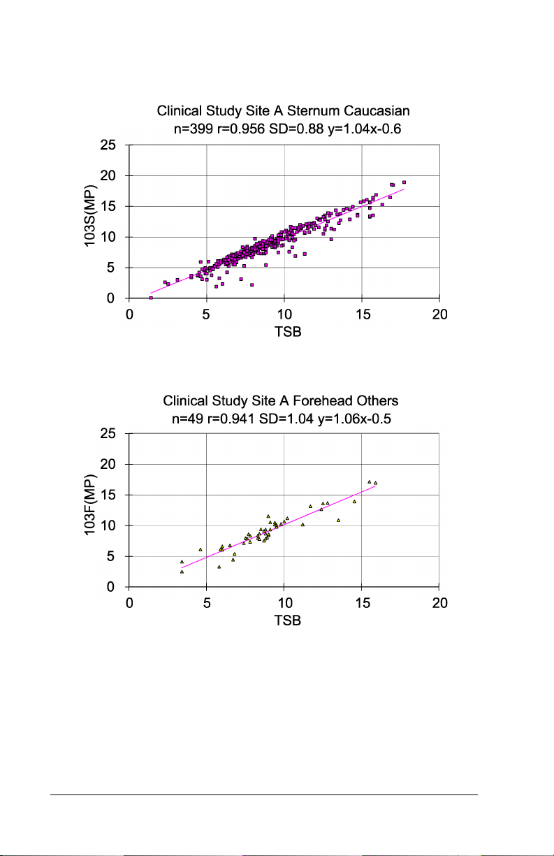
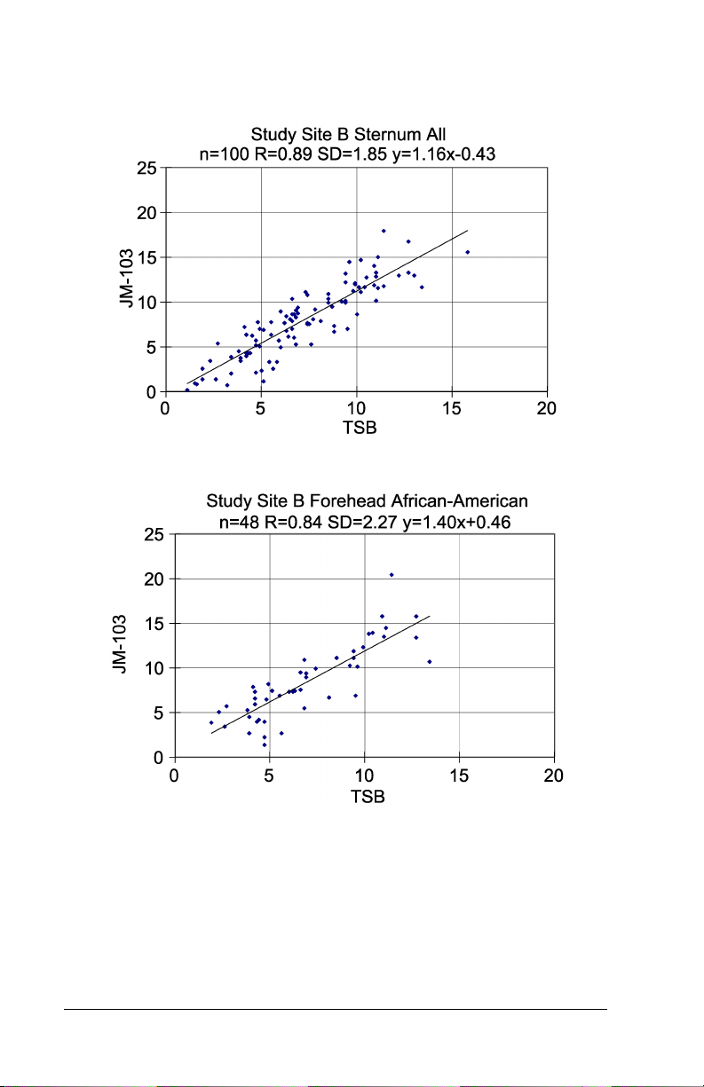
The data in the following sections, as well as Appendix B, is provided to
demonstrate the performance of the Jaundice Meter. This series of
graphs shows the correlation of the estimated bilirubin concentration
taken non-invasively with the JM-103 to the actual serum bilirubin
concentration measured from a blood sample taken from the patient
(TSB) as explained in Sections 4 and 5. The device operates over a
range of 0.0 – 20.0 mg/dL (0 – 340 μmol/L). The data include graphs in
the form of x-y plots where x is the total serum bilirubin concentration
measured and y is the JM-103 estimated bilirubin measurement. Refer
to the graphics results provided in this appendix for the results of studies
at hospital sites. To address device performance in doctors’ office
setting, a study of 201 infants was performed. Results showed similar
performance at doctors’ offices as shown in Appendix B. The data for
the doctors’ office setting contained no forehead measurements as all
measurements were taken at the sternum. This data correlated well with
prior sternum data (refer to page A-12). The serum bilirubin
measurements were taken using direct spectrophotometry in Clinical
Study A and specifically with the Beckman-Coulter Synchron LX-20 in
Hospital Study B. Both systems were used in the doctors’ office study as
well.
Graph 1 – Hospital Study Site A All Patients, Forehead
Jaundice Meter Instructions for Use (MU01380) Page A - 3
Page 60

DRAFT 20 June 2005
Graph 2 – Hospital Study Site A All Patients, Sternum
Graph 3 – Hospital Study Site A African-American Patients, Forehead
Page A - 4 Jaundice Meter Instructions for Use (MU01380)
Page 61

DRAFT 20 June 2005
Graph 4 – Hospital Study Site A African-American Patients, Sternum
Graph 5 – Hospital Study Site A Caucasian Patients, Forehead
Jaundice Meter Instructions for Use (MU01380) Page A - 5
Page 62
DRAFT 20 June 2005
Graph 6 – Hospital Study Site A Caucasian Patients, Sternum
Graph 7 – Hospital Study Site A Other Patients, Forehead
Page A - 6 Jaundice Meter Instructions for Use (MU01380)
Page 63

DRAFT 20 June 2005
Graph 8 – Hospital Study Site A Other Patients, Sternum
Graph 9 – Hospital Study Site B All Patients, Forehead
Jaundice Meter Instructions for Use (MU01380) Page A - 7
Page 64
DRAFT 20 June 2005
Graph 10 – Hospital Study Site B All Patients, Sternum
Graph 11– Hospital Study Site B African-American Patients, Forehead
Page A - 8 Jaundice Meter Instructions for Use (MU01380)
Page 65

DRAFT 20 June 2005
Graph 12 – Hospital Study Site B African-American Patients, Sternum
Graph 13 – Hospital Study Site B Caucasian Patients, Forehead
Jaundice Meter Instructions for Use (MU01380) Page A - 9
Page 66

DRAFT 20 June 2005
Graph 14 – Hospital Study Site B Causasian Patients, Sternum
Graph 15 – Hospital Study Site B Other Patients, Forehead
Page A - 10 Jaundice Meter Instructions for Use (MU01380)
Page 67

DRAFT 20 June 2005
Graph 16 – Hospital Study Site B Other Patients, Sternum
Jaundice Meter Instructions for Use (MU01380) Page A - 11
Page 68

DRAFT 20 June 2005
Table 1: Summary Table of Slope, Intercept, Standard
Deviation, and Correlation Coefficients for Each Graph
Study Site / Patient
Population
SITE A Forehead All
(n=513)
SITE A Sternum All
(n=513)
SITE A Forehead African-American (n=65)
SITE A Sternum African-American (n=65)
SITE A Forehead Caucasian (n=399)
SITE A Sternum Caucasian (n=399)
SITE A Forehead Other
(n=49)
SITE A Sternum Other
(n=49)
SITE B Forehead All
(n=100)
SITE B Sternum All
(n=100)
SITE B Forehead African-American (n=48)
SITE B Sternum African-American (n=48)
SITE B Forehead Caucasian (n=35)
SITE B Sternum Caucasian (n=35)
SITE B Forehead Other
(17)
SITE B Sternum Other
(17)
Correlation
Slope Intercept
1.05 -0.35 0.914 1.29
1.07 -0.74 0.946 1.02
1.15 -0.5 0.908 1.59
1.11 -0.4 0.908 1.55
1.01 -0.1 0.916 1.2
1.04 -0.6 0.956 0.88
1.06 -0.5 0.941 1.04
1.10 -1.0 0.977 0.65
1.07 -0.00 0.84 2.14
1.16 -0.43 0.89 1.85
1.40 +0.46 0.84 2.27
1.21 -0.17 0.89 1.9
1.10 -1.04 0.87 1.72
1.22 -1.69 0.88 1.81
1.03 -0.56 0.94 1.49
1.03 0.65 0.97 0.94
Coefficient
(r)
Standard
Deviation
(RMSE)
Page A - 12 Jaundice Meter Instructions for Use (MU01380)
Page 69

DRAFT 20 June 2005
Graph 17 – Hospital Study Site A Error Plot, Forehead
Graph 18 – Hospital Study Site A Error Plot, Sternum
Jaundice Meter Instructions for Use (MU01380) Page A - 13
Page 70

DRAFT 20 June 2005
Graph 19 – Hospital Study Site B Error Plot, Forehead
Graph 20 – Hospital Study Site B Error Plot, Sternum
Page A - 14 Jaundice Meter Instructions for Use (MU01380)
Page 71

DRAFT 20 June 2005
Graph 21 – Infant Weight Distribution
Infant Weight
(grams)
Hospital Study A Hospital Study B
Up to 999 6 2
1000 - 1499 15 0
1500 - 1999 23 13
2000 - 2499 37 23
2500 - 2999 68 19
3000 - and up 337 43
Unknown 27 0
Total 513 100
Graph 22 – Hospital Study Site A Birthweight Error Plot, Forehead
Jaundice Meter Instructions for Use (MU01380) Page A - 15
Page 72

DRAFT 20 June 2005
Graph 23 – Hospital Study Site A Birthweight Error Plot, Sternum
Reproducibility
Reproducibility of the light output of the device was tested daily using
the checker. The checker determines the intensity of the light output of
the device. The accuracy of the device is determined by how well the
detectors in the unit measure the returning light. The results of the
device testing using the checker show that the device produced output
within the required range over the course of both hospital studies.
Reproducibility testing in the patient population can be derived from the
data taken in Hospital study site A. The reproducibility data is based on
467 infants. Three independent measurements were taken at each site—
forehead and sternum. Each measurement was recorded, and the mean
and standard deviation were computed and recorded. The average
standard deviation for forehead and sternum measurements was 0.3 for
both.
Page A - 16 Jaundice Meter Instructions for Use (MU01380)
Page 73

DRAFT 20 June 2005
Table 2: Reproducibility Data
Mean
Estimated
Bilirubin
Measure
ment
Body Site
Deviation
Range
Deviation
Mean
Deviation
Median
Range
(mg/dL)
Sternum 0.0 - 2.2 0.3 0.3 0.8 - 18.5
Forehead 0.0 - 2.6 0.3 0.2 0.1 - 19.5
Conclusion
The data shows that the estimated bilirubin concentration measurement
from the Jaundice Meter correlates to the serum bilirubin measurements.
This data supports the use of this non-invasive device along with other
clinical indicators as an aid in the management of jaundice in the
neonatal patient population.
Jaundice Meter Instructions for Use (MU01380) Page A - 17
Page 74

DRAFT 20 June 2005
Page intentionally left blank.
Page A - 18 Jaundice Meter Instructions for Use (MU01380)
Page 75

DRAFT 20 June 2005
Appendix B
Doctors’ Office Data
Study Design
Studies were performed at two doctors’ office sites comparing JM-103
Total Calculated Bilirubin (TcB) to laboratory measured total serum
bilirubin (TSB).
Selection Criteria
The ages of the infants in the study ranged from approximately 24 hours
to 7-10 days, with a mean of 3 days (at site 1) and 5 days (at site 2). The
test was performed on infants who were determined by their physician
to require a serum bilirubin test.
Demographics of Patient Population
All patients meeting the above criteria were included in the study. The
majority of babies were Caucasian or no skin tone noted (n=167) with a
small number of reported ethnicity defined infants (n=34). The
demographics of the patient population included Caucasian, AfricanAmerican, and other.
Jaundice Meter Instructions for Use (MU01380) Page B - 1
Page 76

DRAFT 20 June 2005
The doctor's office study was composed of the following ethnic groups:
TcB Range Qty Age
Caucasian 2.3-19.5 167
AfricanAmerican
Mid-Eastern 8.8 - 16.0 5
Indian 6.6- 17 5
Hispanic 7.6 1
Asian 4.8-12.6 10
NOTE:
Doctor’s Office #1: 83.5% Caucasian and 16.5% darker skin tone
Doctor’s Office #2: 75% Caucasian and 25% darker skin tone
Exclusion Criteria
Infants requiring Exchange Transfusion or Phototherapy Initiated were
not allowed in the study.
Sample Size
The doctors’ office use trial studied 201 patients.
4.9-17.3 13
97
≤72 hrs & 70≥72hrs
6
≤72 hrs & 7≥72hrs
4
≤72 hrs & 1≥72hrs
4
≤72 hrs & 1≥72hrs
3
≤72 hrs & 7≥72hrs
Measurement Selection
Estimated bilirubin measurements taken during the studies ranged from
2.3 to 19.5 mg/dL. No "Averaging of Readings" was used with the JM-
103.
Body Sites Tested
All infants were measured at the sternum location ONLY.
Number of Doctors’ Office Sites
For the doctors’ office study, two sites were chosen for application of
the device. Sample size was 201 patients.
Page B - 2 Jaundice Meter Instructions for Use (MU01380)
Page 77

DRAFT 20 June 2005
Performance Data
The data in the following sections is provided to demonstrate results of
the JM-103 clinical studies, in comparison to total serum bilirubin. The
JM-103 reports values over a range of 0-20 mg/dL estimated bilirubin.
Although the doctor's office study showed correlation of JM-103 to the
TSB laboratory values, the relationship (bias) of the JM-103 to the TSB
values was somewhat different than previously reported for hospital
sites (as previously shown in Appendix A). This may be related to the
ages of the infants in the doctor's office study and the difference in
individual development. Therefore, please be aware that results at
doctors offices may differ from results at hospitals and may have more
variability.
The reported data shows that 27% of the JM-103 measurements were
higher than the Laboratory TSB and 71% were lower (2% were matched
sets). Of the readings falling below the TSB value, 87% were within 3
Mg/dL of the TSB value. Those readings that reported above the TSB
value 94% were within 3 Mg/dL of the reported TSB value. The largest
error was a single 5.2 Mg/dL reading. The serum bilirubin
measurements were taken using direct spectrophotometry and the
Beckman-Coulter Synchron LX-20.
See regression analysis and infant age graphs below for data at the
individual sites. A regression analysis is also provided on the total of
201 infants.
Jaundice Meter Instructions for Use (MU01380) Page B - 3
Page 78

DRAFT 20 June 2005
Graph 1 – Infant Age, Doctor’s Office #1
Graph 2 – Infant Age, Doctor’s Office #2
Page B - 4 Jaundice Meter Instructions for Use (MU01380)
Page 79

DRAFT 20 June 2005
Graph 3 – Regression Analysis, Doctors’ Office #1
JM-103 Regression Analysis
30
25
20
15
10
5
JM-103 Reading TcB Mg/dl
0
0 5 10 15 20 25 30
Doctor's office No.1
-5
Serum Bilirubin TSB (mg/dl)
Regression Line Upper Limit Low er Limit Data Points
Regression Analysis Statistics Sample Size (n) = 133.
Y = -0.636 + 0.977 X
Root Mean Square Error (MSE) = 1.572
R-Square = 0.804
95% Confidence Interval (CI) for the Intercept = (-1.526, 0.254)
95% CI for the Slope = (0.894, 1.061)
Jaundice Meter Instructions for Use (MU01380) Page B - 5
Page 80

DRAFT 20 June 2005
Graph 4 – Regression Analysis, Doctors’ Office #2
JM-103 Regression Analysis
25
20
15
10
5
JM-103 Reading TcB Mg/dl
0
0 5 10 15 20 25 30
-5
Doctor's Office No.2
Serum Bilirubin TSB (mg/dl)
Regression Line Upper Limit Low er Limit Data Points
Regression Analysis Statistics Sample Size = 68
Y = 0.646 +0.859 X
Root MSE = 1.475
R-Square = 0.769
95% CI for the Intercept = (-0.846, 2.138)
95% CI for the Slope = (0.743, 0.974)
Page B - 6 Jaundice Meter Instructions for Use (MU01380)
Page 81

DRAFT 20 June 2005
Graph 5 – Regression Analysis, Doctors’ Office Setting, 2 Locations
JM-103 Regression Analysis
30
25
20
15
10
5
JM-103 Measurement Mg/dl
0
0 5 10 15 20 25 30
Doctor's office setting - 2 locations
-5
Serum Bilirubin TSB (mg/dl)
Regression Line Upper Limit Low er Limit Data Points
Regression Analysis Statistics Sample Size = 201
Y = 0.233 +0.934 X
Root MSE = 1.54
R-Square = 0.899
95% CI for the Intercept = (-0.233, 0.37)
95% CI for the Slope = (0.934, 0.032)
Jaundice Meter Instructions for Use (MU01380) Page B - 7
Page 82

DRAFT 20 June 2005
Conclusion
The data show that the Jaundice Meter estimated bilirubin concentration
measurement correlates to the serum bilirubin measurements. This data
supports the use of this non-invasive device along with other clinical
indicators as an aid in the management of jaundice in the neonatal
patient population.
Page B - 8 Jaundice Meter Instructions for Use (MU01380)
Page 83

DRAFT 9 Nov 2004
Appendix C
Medical and Scientific References on
Transcutaneous Bilirubinometry
1. Amato M, Pasquier S, de Muralt G. Transcutaneous bilirubin determination: correlation in white premature infants weighing less than
1500 gm [in French]. Schweiz Med Wochenschr. 1985;115(27-
28):937-938.
2. Amato M, Huppi P, Markus D. Assessment of neonatal jaundice in
low birth weight infants comparing transcutaneous, capillary and
arterial bilirubin levels. Eur J Pediatr. 1990;150(1):59-61.
3. Amato M. Transcutaneous, capillary, and arterial bilirubin levels
[letter]. J. Pediatr. 1994;125(2):332.
4. Amit Y, Jabbour S, Arad ID. Effect of skinfold thickness on transcutaneous bilirubin measurements. Biol Neonate. 1993;63(4):209-
214.
5. Arimichi J, Tanaka N, Shibata R, Dei T, Kamihara K. Reliability
and future application of a transcutaneous bilirubinometer [in Japanese]. Josanpu Zasshi. 1984;38(4):316-321.
6. Berget M, Finne PH. Transcutaneous bilirubinometry in newborn
infants [in Norwegian]. Tidsskr Nor Laegeforen. 1984;104(14):984-
986.
7. Bhat V, Srinivasan S, Usha TS, Puri RK. Correlation of transcutaneous bilirubinometry with serum bilirubin in south Indian neonates. Indian J Med Res. 1987;86:49-52.
8. Bhutta ZA, Yusuf K. Transcutaneous bilirubinometry in Pakistani
newborns: a preliminary report. J Pak Med Assoc, 1991;41(7):155-
156.
9. Boo NY, Bakar AA. Transcutaneous bilirubinometry in Malay, Chinese and Indian term neonates. Med J Malaysia., 1984;39(1):35-37.
10. Bourchier D, Cull AB, Oettli PE. Transcutaneous bilirubinometry:
22 months experience at Waik a to Women' s H ospita l . N Z Med J.
1987;100(832):599-600.
11. Brown AK, Kim MH, Nuchpuckdee P, Boyle G. Transcutaneous
bilirubinometry in infants: influence of race and phototherapy.
Pediatr Res. 1981;15(4)(Supplement):653.
Jaundice Meter Instructions for Use (MU01380) Page C - 1
Page 84

DRAFT 9 Nov 2004
12. Brown LP, Arnold L, Allison D, Jacobsen B, Klein ME, Charsha D.
Transcutaneous bilirubinometer: intermeter reliability. J Perinatol.
1990;10(2):167-169.
13. Brown L, Arnold L, Charsha D, Allison D, Klein ME. Transcutaneous bilirubinometer: an instrument for clinical research. Nurs Res.
1990;39(4):241-243.
14. Brown LP, Arnold L, Allison D, Klein H, Jacobsen B. Incidence
and pattern of jaundice in healthy breast-fed infants during the first
month of life. Nurs Res. 1993;42(2):106-110.
15. Brucker MC, MacMullen NJ. Neonatal jaundice in the home:
assessment with a noninvasive device. J Obstet Gynecol Neonatal
Nurs. 1987;16(5):355-358.
16. Cassady G. Transcutaneous monitoring in the newborn infant. J
Pediatr. 1983;103(6):837-848.
17. Chen ZL, Liu AY. Clinical use of transcutaneous bilirubinometry
[in Chinese]. Zhonghua Y; Xue Za Zih. 1986;66(1):19-21.
18. Christo GG, Kamath S, Aroor AR, Venkatesh A. Transcutaneous
bilirubinometry in newborns. Indian Pediatr. 1988;25(11):1073-
1077.
19. Corchia C, Vetrano G. Comment on transcutaneous bilirubin device
of Yamanouchi [letter]. Pediatrics. 1981;67(3):442.
20. Dai J, Krahn J, Parry DM. Clinical impact of transcutaneous bilirubinometry as an adjunctive screen for hyperbilirubinemia. Clin Bio-
chem. 1996;29(6):581-586.
21. Dai J, Parry DM, Krahn J. Transcutaneous bilirubinometry: its role
in the assessment of neonatal jaundice. Clin Biochem.
1997;30(1):1-9.
22. Derksen-Samsom JF, Versluys C, Bezemer PD. The reliability of
transcutaneous bilirubin measurement: a clinical study with statistical data and literature review [in Dutch]. Tijdschr Kindergeneeskd.
1984;52(5):181-186.
23. Dominguez Ortega F, Ormazabal Ramos JC, Martin Zarza M,
Domenech Martinez E. Transcutaneous bilirubinometry: correlation of the reading site obtained with spectrophotometry and diazoreaction technique [in Spanish]. An Esp Pediatr. 1993;39(5):438-
440.
Page C - 2 Jaundice Meter Instructions for Use (MU01380)
Page 85

DRAFT 9 Nov 2004
24. Douville P, Masson M, Forest JC. Diagnostic value of sequential
readings with the Minolta transcutaneous bilirubinometer in normal
and low-birthweight infants [letter]. Clin Chem. 1983;29(4):740-
741.
25. Fabris C, Licata D, Roberi P, et al. Evaluation of transcutaneous
bilirubinometry in newborn infants [in Italian]. Minerva Pediatr.
1984;36(11):565-570.
26. Foged N, Kristensen GB, Kamper J. Transcutaneous bilirubinometry. A non-invasive method of measuring physiological jaundice [in
Danish]. Ugeskr Laeger. 1983;145(38):2935-2937.
27. Fok TF, Lau SP, Hui CW, Fung KP, Wan CW. Transcutaneous
bilirubinometer: its use in Chinese term infants and the effect of
haematocrit and phototherapy on the TcB index. Aust Paediatr J.
1986;22(2):107-109.
28. Galletto P, Vignolo Lutati C, Farina D, Gavinelli R. Supervision of
neonatal jaundice by use of the transcutaneous bilirubinometer [in
Italian]. Minerva Pediatr. 1983;35(1-2):51-55.
29. Goldman SL, Peñalver A, Perñaranda R. Jaundice meter: evaluation
of new guidelines. J Pediatr. 1982;101(2):253-256.
30. Grande R, Gutierrez E, Latorre E, Arguelles F. Physiological variations in the pigmentation of newborn infants. Hum Biol.
1994;66(3):495-507.
31. Hannemann RE, Dewitt DP, Hanley EJ, Schreiner RL, Bonderman
P. Determination of serum bilirubin by skin reflectance: effect of
pigmentation. Pediatr Res. 1979;13(12):1326-1329.
32. Hannemann RE, Schreiner RL, DeWitt DP, Norris SA, Glick MR.
Evaluation of the Minolta bilirubin meter as a screening device in
white and black infants. Pediatrics. 1982;69(1):107-109.
33. Hegyi T, Hiatt IM, Indyk L. Transcutaneous bilirubinometry. I. Correlations in term infants. J Pediatr. 1981;98(3):454-457.
34. Hegyi T, Hiatt IM, Gertner I, Indyk L. Transcutaneous bilirubinometry. The cephalocaudal progression of dermal icterus. Am J Dis
Child. 1981;135(6):547-549.
35. Hegyi T. Transcutaneous bilirubinometry: a new light on an old
subject. Pediatrics. 1982;69(1):124-125.
36. Hegyi T, Hiatt IM, Gertner IM, Zanni R, Tolentino T. Transcutaneous bilirubinometry II. Dermal bilirubin kinetics during phototherapy. Pediatr Res. 1983;17(11):888-891.
Jaundice Meter Instructions for Use (MU01380) Page C - 3
Page 86

DRAFT 9 Nov 2004
37. Hegyi T. Transcutaneous bilirubinometry in the newborn infant:
state of the art. J Clin Monit. 1986;2(1):53-59.
38. Hegyi T, Graff M, Zapanta V, Hiatt IM, Sisson TR. Transcutaneous
bilirubinometry. III. Dermal bilirubin kinetics under green and blue
light phototherapy. Am J Dis Child. 1986;140(10):994-997.
39. Heick C, Mieth D, Fallenstein F, Schubiger G, Nars PW, Amato M.
Transcutaneous bilirubin determination in the newborn infant. Recommendations of the Swiss Neonatology Group [in German]. Helv
Paediatr Acta. 1982;37(6):589-597.
40. Hodr R, Mandys F, Kepertova M. Transcutaneous measurement of
the severity of icterus and bilirubinemia in normal neonates [in
Czech]. Cesk Pediatr. 1990;45(11):655-658.
41. Hung WT, Su CT. Diagnosis of atretic prolonged obstructive jaundice; technetium 99m hepatolite excretion study. J Pediatr Surg.
1990;25(7):797-800.
42. Karrar Z, al Habib S, al Basit OB, Ashong F, Osundwa V. Transcutaneous bilirubin measurements in Saudi infants: the use of the
jaundice meter to identify significant jaundice. Ann Trop Paediatr.
1989;9(1):59-61.
43. Kenny M, Metzger G, Landicho D, Chow J. Transcutaneous bilirubin monitoring of newborns. Ann N Y Acad Sci. 1984;428:251-262.
44. Keshishjan ES, Antonov AG, Baybarina VS, Antonov VS, Davydov VM. Diagnostics and control of newborn hyperbilirubinemia
with use noninvasive transcutaneous photometric analyzer "Bilitest" of a type AHP-02. The methodical recommendations. Russia
ministry of public health. 1992.
45. Keshishjan ES, Antonov VS, Davydov VM, Prischepa MI. Transcutaneous bilirubinometry method at newborn jaundice diagnostics
and control. The Russian bulletin perinatology and pediatrics.
1993;38(5).
46. Keshishjan ES, Ovanesov EN, Prishchepa MI. Use of the method of
transcutaneous bilirubinometry in hyperbilirubinemia in the newborn [in Russian]. Klin Lab Diagn. 1994;(5):17-20.
47. Kivlahan C, James EJ. The natural history of neonatal jaundice.
Pediatrics. 1984;74(3):364-370.
48. Knudsen A. Prediction of the development of neonatal jaundice by
increased umbilical cord blood bilirubin. Acta Paediatr Scand.
1989;78(2):217-221.
Page C - 4 Jaundice Meter Instructions for Use (MU01380)
Page 87

DRAFT 9 Nov 2004
49. Knudsen A, Brodersen R. Skin colour and bilirubin in neonates.
Arch Dis Child. 1989;64(4):605-609.
50. Knudsen A, Lebech M. Maternal bilirubin, cord bilirubin, and placenta function at delivery and the development of jaundice in
mature newborns. Acta Obstet Gynecol Scand. 1989;68(8):719-724.
51. Knudsen A. The cephalocaudal progression of jaundice in newborns in relation to the transfer of bilirubin from plasma to skin.
Early Hum Dev. 1990;22(1):23-28.
52. Knudsen A. Measurement of the yellow colour of the skin as a test
of hyperbilirubinemia in mature newborns. Acta Paediatr Scand.
1990;79(12):1175-1181.
53. Knudsen A. Maternal smoking and the serum bilirubin concentration in the first three days of life. Eur J Obstet Gynecol Reprod Biol.
1991;40(2):123-127.
54. Knudsen A. The influence of the reserve albumin concentration and
pH on the cephalocaudal progression of jaundice in newborns.
Early Hum Dev. 1991;25(1):37-41.
55. Knudsen A. The influence of the basal yellow colour of the skin at
birth on later jaundice meter readings in mature newborn infants.
Acta Paediatr. 1992;81(6-7):494-497.
56. Knudsen A. Prediction of later hyperbilirubinemia by measurement
of skin colour on the first postnatal day and from cord blood bilirubin. Dan Med Bull. 1992;39(2):193-196.
57. Knudsen A. Predicting the need for phototherapy in healthy mature
neonates using transcutaneous bilirubinometry on the first postnatal
day. Biol Neonate. 1995;68(6):398-403.
58. Knudsen A, Ebbessen F. Transcutaneous evaluation of icterus in
healthy mature newborn infants. A substitution for blood tests [in
Danish]. Ugeskr Laeger. 1995;157(11):1509-1513.
59. Knudsen A, Ebbesen F. Transcutaneous bilirubinometry in neonatal
intensive care units. Arch Dis Child Fetal Neonatal Ed.
1996;75(1):F53-F56.
60. Kumar A. Micro-invasive management of neonatal bilirubinemia.
Indian Pediatr. 1992;29(9):1101-1106.
61. Kumar A, Faridi MM, Singh N, Ahmad SH. Transcutaneous bilirubinometry in the management of bilirubinemia in term neonates.
Indian J Med Res. 1994;99:227-230.
62. Laeeq A, Yasin M, Chaudhry AR. Transcutaneous bilirubinometry:
clinical application. J Pak Med Assoc. 1993;43(2):28-30.
Jaundice Meter Instructions for Use (MU01380) Page C - 5
Page 88

DRAFT 9 Nov 2004
63. Lebrun F, Sender A, Goujard J, Francoual C, Amiel-Tison C. Clinical evaluation of transcutaneous bilirubinometry [in French]. Ann
Pediatr (Paris). 1982;29(7):494-498.
64. Lin YJ, Ju SH, Lin CH. The clinical application of transcutaneous
bilirubinometry in full-term Chinese infants. Ahonghua Min Guo
Xiao Er Ke Yi Xue Hui Za Zhi. 1993;34(2):69-76.
65. Linder N, Regev A, Gazit G, et al. Noninvasive determination of
neonatal hyperbilirubinemia: standardization for variation in skin
color. Am J Perinatol. 1994;11(3):223-225.
66. Loong EP, Lao TT, Chin RK. Changes in neonatal transcutaneous
bilirubinometer index following intravenous fluid and oxytocin
infusion during labour. Asia Oceania J Obstet Gynaecol.
1988;14(4):411-414.
67. Maisels MJ, Baltz, RD, Bhutani VK, Newman TB, Palmer HP,
Rosenfeld W, Stevenson DK, Weinblatt HB. Management of hyperbilirubinemia in the newborn infant 35 or more weeks of gestation
[in English]. Pediatrics. 2004;114:297-316.
68. Maisels MJ, Conrad S. Transcutaneous bilirubin measurements in
full-term infants. Pediatrics. 1982;70(3):464-467.
69. Maisels MJ, Lee C. Transcutaneous bilirubin measurements: variation in meter response. Pediatrics. 1983;71(3):457-459.
70. Maisels MJ, Kring E. Transcutaneous bilirubin levels in the first 96
hours in a normal newborn population of ≥ 35 weeks’ gestation [in
English]. Pediatrics. 2006;117(4):1169-1175.
71. Maisels MJ, Kring E. Transcutaneous bilirubinometry decreases the
need for serum bilirubin measurements and saves money. Pediat-
rics. 1997;99(4):599-601.
72. Maisels MJ, Ostrea EM, Touch S, Clune SE, Cepeda E, Kring E,
Gracey K, Jackson C, Talbot D, Huang R. Evaluation of a new transcutaneous bilirubinometer [in English]. Pediatrics.
2004;113:1628-1635.
73. Melton K, Akinbi HT. Neonatal jaundice: strategies to reduce
bilirubin-induced complications [in English]. Postgraduate Medi-
cine online. 1999;106(6).
74. Moscicka A, Gadzinowski J, Moscicki A, Breborowicz CH, Opala
T. Usefulness of transcutaneous measurements of bilirubin in
infants with jaundice [in Polish]. Ginekol Pol. 1994;65(6):271-275.
Page C - 6 Jaundice Meter Instructions for Use (MU01380)
Page 89

DRAFT 9 Nov 2004
75. Myara A, Sender A, Valette V, et al. Early changes in cutaneous
bilirubin and serum bilirubin isomers during intensive phototherapy
of jaundiced neonates with blue and green light. Biol Neonate.
1997;71(2):75-82.
76. Onks D, Silverman L, Robertson A. Effect of melanin, oxyhemoglobin and bilirubin on transcutaneous bilirubinometry. Acta Paedi-
atr. 1993;82(1):19-21.
77. Pallas Alonso C, Martin Puerto MJ, Mendoza Soto A, Bustos Lozano G, Flores Anton B, Orbea Gallardo C. Transcutaneous bilirubin
measurement in neonates [in Spanish]. An Esp Pediatr.
1993;38(1):33-37.
78. Palmer DC, Zenner EM, Drew JH. Transcutaneous bilirubinometry:
use in Australia. Aust Paediatr J. 1982;18(4):273-276.
79. Palmer DC, Drew JH. Jaundice: A 10 year review of 41,000 live
born infants. Aust Paediatr J. 1983;19(2):86-89.
80. Peng DJ, Zhu YL, Qiao ZK, Xiong FK, Li YF. A study of the effect
of pathologic factors on the TcBM readings [in Chinese]. Hua Xi Yi
Ke Da Xue Xue Bao. 1989;20(1):70-73.
81. Petrova A, Mehta R, Birchwood G, Ostfeld B, Hegyi T. Management of neonatal hyperbilirubinemia: pediatricians’ practices and
educational needs [in English]. Neonatal Intensive Care.
2006;19(7):39-43.
82. Romo-Pinales J, Orozco-Gutierrez A, Udaeta-Mora E, GrahamPontones S. Preliminary study in Mexico on the use of the transcutaneous bilirubinometer [in Spanish]. Bol Med Hosp Infant Mex.
1984;41(10):536-538.
83. Ruchala PL, Seibold L, Stremsterfer K. Validating assessment of
neonatal jaundice with transcutaneous bilirubin measurement. Neo-
natal Netw. 1996;15(4):33-37.
84. Salmeron Escobar FJ. Differential diagnosis of jaundice [in Spanish]. Rev Esp Enferm Dig. 1991;79(1):37-42.
85. Schubiger G, Mullis P, Korber HR. Transcutaneous determination
of bilirubin in the neonatal department: an analysis of its uses [in
German]. Helv Paediatr Acta. 1986;41(3):183-186.
86. Schumacher RE, Thornbery JM, Gutcher GR. Transcutaneous
bilirubinometry: a comparison of old and new methods. Pediatrics.
1985;76(1):10-14.
87. Schumacher RE. Noninvasive measurements of bilirubin in the
newborn. Clin Perinatol. 1990;17(2):417-435.
Jaundice Meter Instructions for Use (MU01380) Page C - 7
Page 90

DRAFT 9 Nov 2004
88. Serrao PA, Modanlou HD. Significance of anti-A and anti-B isohemagglutinins in cord blood of ABO incompatible newborn infants:
correlation with hyperbilirubinemia. J Perinatol. 1989;9(2):154-
158.
89. Sharma JN, Singh RN, Lodha A, Singh J. Transcutaneous bilirubinometry in newborns. Indian Pediatr. 1988;25(8):757-760.
90. Sheridan-Pereira M, Gorman W. Transcutaneous bilirubinometry:
an evaluation. Arch Dis Child. 1982;57(9):708-710.
91. Smith DW, Inguillo D, Martin D, Vreman HJ, Cohen RS, Stevenson
DK. Use of noninvasive tests to predict significant jaundice in fullterm infants: preliminary studies. Pediatrics. 1985;75(2):278-280.
92. Strange M, Cassady G. Neonatal transcutaneous bilirubinometry.
Clin Perinatol. 1985;12(1):51-62.
93. Suckling RJ, Laing IA, Kirk JM. Transcutaneous bilirubinometry
as a screening tool for neonatal jaundice. Scott Med J.
1995;40(1):14-15.
94. Taha SA, Karrar ZA, Dost SM. Transcutaneous bilirubin measurement in evaluating neonatal jaundice among Saudi newborns. Ann
Trop Paediatr. 1984;4(4):229-231.
95. Tan KL. Transcutaneous bilirubinometry in Chinese and Malay
neonates. Ann Acad Med Singapore. 1985;14(4):591-594.
96. Tan KL, Mylvaganam A. Transcutaneous bilirubinometry in preterm very low birthweight infants. Acta Paediatr Scand.
1988;77(6):796-801.
97. Tan KL, Lim GC, Boey KW. Efficacy of phototherapy for hyperbilirubinaemia in infants with the respiratory distress syndrome. J
Paediatr Child Health. 1995;31(2):127-129.
98. Tan KL, Chia HP, Koh BC. Transcutaneous bilirubinometry in Chinese, Malay and Indian infants. Acta Paediatr. 1996;85(8):986-990.
99. Tsai LT, Lu CC. Clinical evaluation of transcutaneous jaundice
meter in full-term newborns. Zhonghua Min Guo Xiao Er Ke Yi Xue
Hui Za Zhi. 1988;29(6):376-382.
100. Tudehope DI, Chang A. Non-invasive method of measuring bilirubin levels in newborn infants. Med J Aust. 1982;1(4):165-168.
101. Tudehope DI, Chang A. Multiple site readings from a transcutaneous bilirubinometer. Aust Paediatr J. 1982;18(2):102-105.
Page C - 8 Jaundice Meter Instructions for Use (MU01380)
Page 91

DRAFT 9 Nov 2004
102. Uchida K, Kaneoka T, Ichihara J, Shirakawa K. Fundamental studies on transcutaneous bilirubinometry in newborn infants using an
organ scanning spectrophotometer [in Japanese]. Nippon Sanka
Fujinka Gakkai Zasshi. 1988;40(2):167-173.
103. Utchajkin VF, Baranova EB, Ovanesov EN, Setsko IV. Clinical
importance of noninvasive bilirubinemia monitoring by children
viral hepatitis. 2-nd Symposiums "Noninvasive Methods of Diag-
nostics". The thesis of the reports. Moscow. [in Russian]. 1995.
104. Vaisman S, Hinrichsen M. Clinical trial of a transcutaneous bilirubinometer [in Spanish]. Rev Chil Pediatr. 1983;54(2):83-86.
105. Veleminsky M. The significance of transcutaneous measurement of
"bilirubin" in neonates [in Czech]. Cesk Pediatr. 1992;47(11):683.
106. Vocel J, Mrastíková H, Reitschlägerová V. Transcutaneous bilirubinometry using the Minolta/Air-Shields in neonates [in Czech]. Cesk
Pediatr. 1985;40(11):649-651.
107. Vocel J, Jezková Z, Reitschlägerová V. Transcutaneous bilirubinometry using the Minolta/Air-Shields apparatus in neonates with a
low birthweight [in Czech]. Cesk Pediatr. 1987;42(1):20-22.
108. Vocel J, Petrová L, Concha Gonzales J, Paulová M, Reitschlägerová
V. Transcutaneous bilirubinometry in neonates with hyperbilirubinemia treated with phototherapy [in Czech]. Cesk Pediatr.
1988;43(12):742-743.
109. Weiss WJ, Rosenberg G, Snyder AJ, et al. A completely implanted
left ventricular assist device. Chronic in vivo testing. ASAIO J
1993;39(3):M427-M432.
110. Yamanouchi I, Yamauchi Y, Igarashi I. Transcutaneous bilirubinometry: preliminary studies of noninvasive transcutaneous bilirubin meter in the Okayama National Hospital. Pediatrics.
1980;65(2):195-202.
111. Yamauchi Y, Yamanouchi I. Transcutaneous bilirubinometry. Effect
of irradiation on the skin bilirubin index. Biol Neonate.
1988;54(6):314-319.
112. Yamauchi Y, Yamanouchi I. Transcutaneous bilirubinometry. Evaluation of accuracy and reliability in a large population. Acta Paedi-
atr Scand. 1988;77(6):791-795.
113. Yamauchi Y, Yamanouchi I. Transcutaneous bilirubinometry:
bilirubin kinetics of the skin and serum during and after phototherapy. Biol Neonate. 1989;56(5):263-269.
Jaundice Meter Instructions for Use (MU01380) Page C - 9
Page 92

DRAFT 9 Nov 2004
114. Yamauchi Y, Yamanouchi I. Transcutaneous bilirubinometry:
serum bilirubin measurement using transcutaneous bilirubinometer
(TcB). A preliminary study. Biol Neonate. 1989;56(5):257-262.
115. Yamauchi Y, Yamanouchi I. Transcutaneous bilirubinometry in normal Japanese infants. Acta Paediatr Jpn. 1989;31(1):65-72.
116. Yamauchi Y, Yamanouchi I. Transcutaneous bilirubinometry. Interinstrumental variability of TcB instruments. Acta Paediatr Scand.
1989;78(6):844-847.
117. Yamauchi Y, Yamanouchi I. Clinical application of transcutaneous
bilirubin measurement. Early prediction of hyperbilirubinemia.
Acta Paediatr Scand. 1990;79(4):385-390.
118. Yamauchi Y, Yamanouchi I. Transcutaneous bilirubinometry: effect
of postnatal age. Acta Paediatr Jpn. 1991;33(5):663-667.
119. Yamauchi Y, Yamanouchi I. Transcutaneous bilirubinometry: variability of TcB measurements on the forehead with crying. Acta
Paediatr Jpn. 1991;33(5):655-657.
120. Yamauchi Y, Yamanouchi I. Factors affecting transcutaneous bilirubin measurement: effect of daylight. Acta Paediatr Jpn.
1991;33(5):658-662.
121. Yip WC, Teo J, Tay JS. Transcutaneous bilirubinometry [letter].
Acta Paediatr Scand. 1983;72(2):289.
Page C - 10 Jaundice Meter Instructions for Use (MU01380)
Page 93

Page 94

These Instructions for Use only apply to
Jaundice Meter
Model JM-103 International
with the Serial No.:
If no Serial No. has been filled in by Dräger,
these Instructions for Use are provided for general information only and are not intended for
use with any specific machine or device.
This document is provided for customer information only, and will not be updated or exchanged
without customer request.
Directive 93/42/EEC
concerning Medical Device
Manufacturer:
Draeger Medical Systems, Inc.
3135 Quarry Road
Telford, PA 18969
U.S.A.
(215) 721-5400
(800) 4DRAGER
(800 437-2437)
FAX (215) 723-5935
http://www.draeger.com
In Europe, Canada, Middle East, Africa, Latin
America, Asia Pacific distributed by:
Dräger Medical GmbH
Moislinger Allee 53 – 55
D-23542 Lübeck
Germany
FAX +49 451 8 82-20 80
MU01380 RI04 – GA 6016.016 en
© Draeger Medical Systems, Inc.
Edition: 11 – 2010-09
(Edition: 1 – 2002-01)
Dräger reserves the right to make modifications
to the device without prior notice.
+49 451 8 82-0
http://www.draeger.com
Made in Japan
 Loading...