

Page 1
Technical manual
X-am® 3500/8000
HFG 000* / HFG 001*
Page 2

2 Technical manual | X-am® 3500/8000
This page has been left blank intentionally.
Page 3

Page 4
90%
12:02
ppmH S
2
5
90%
12:02
ppmH S
2
90%
11:07
ppmH S
2
10
90%
12:02
H S
2
90%
11:07
ppmH S
2
A
20
90%
12:02
H S
2
90%
11:07
ppmH S
2
A
0%
08:43
C
2
1
OK
2
4
3
6
5
1
OK
A
OK
J
1
2
F
5
OK
G
21 3 4
1
3
2
B
OK
231
D
E
1
2
Switching off...
Battery empty
0 %
2
1
4
5
M
3
4
5%
08:43
Warning
Battery low!
12
K
CAL
4
1
2
3
1
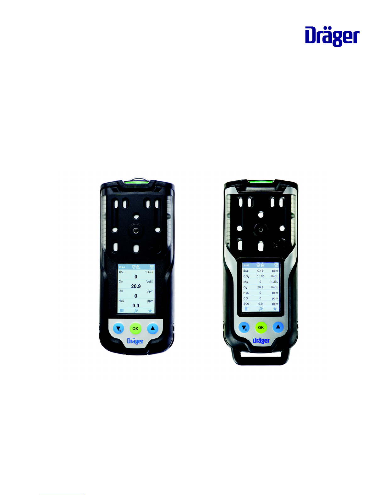
0.0
H S
2
ppm
20.9
Vol%O
2
0
%LELch
4
0
ppmCO
2
1
L
Page 5

Technical manual | X-am® 3500/8000 5
Contents
Contents
1 Safety-related information ......................................................................
8
1.1 Information on safety notes and warnings......................................
8
1.1.1 Safety notes......................................................................
8
1.1.2 Warnings ..........................................................................
8
1.2 Basic safety information..................................................................
8
1.3 Use in areas subject to explosion hazards .....................................
8
2 Conventions in this document ...............................................................
10
2.1 Meaning of the warning notes.........................................................
10
2.2 Trade marks....................................................................................
10
2.3 Typographical conventions.............................................................
10
2.4 Glossary..........................................................................................
10
2.5 Abbreviations ..................................................................................
11
3 Description ...............................................................................................
13
3.1 Product overview ............................................................................
13
3.2 Intended use...................................................................................
14
3.3 Limitations on use...........................................................................
14
3.4 Approvals........................................................................................
14
3.5 Label ...............................................................................................
14
3.6 Sensor slot positions X-am 3500....................................................
14
3.7 Sensor slot positions X-am 8000....................................................
15
3.8 Further device options for X-am 8000 ............................................
15
4 Operation ..................................................................................................
16
4.1 Op
erating concept ..........................................................................
16
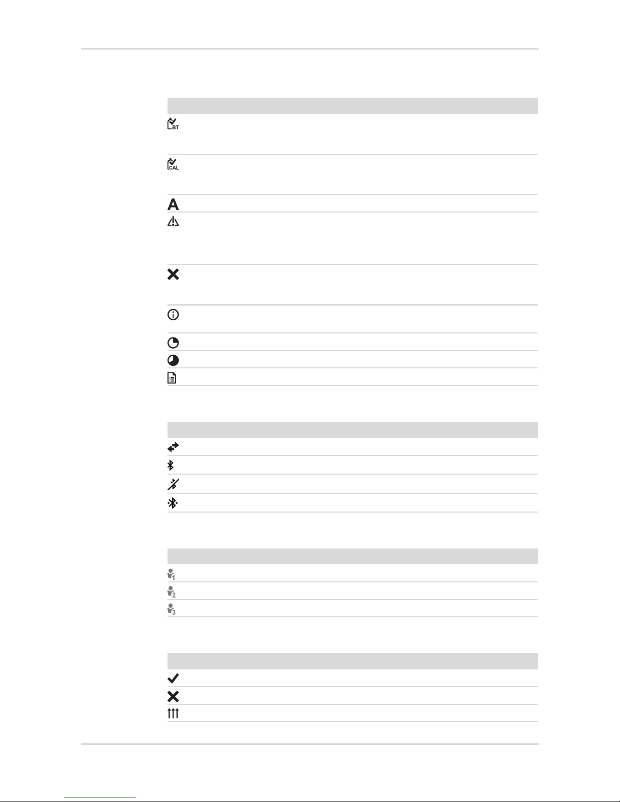
4.2 Symbol explanations.......................................................................
16
4.2.1 feature buttons..................................................................
16
4.2.2 Displays ............................................................................
16
4.2.3 Application ........................................................................
16
4.2.4 Device status ....................................................................
17
4.2.5 Connection .......................................................................
17
4.2.6 User level..........................................................................
17
4.2.7 Display in gas channel......................................................
17
4.3 Signalling concept...........................................................................
18
4.3.1 Acoustic operation signal..................................................
18
4.3.2 Visual operation signal .....................................................
18
4.3.3 Visual operation signal with activated D-Light..................
18
4.4 Switch the gas detector on or off ....................................................
18
4.4.1 Initial start-up ....................................................................
18
4.4.2 Switching on the gas detector ..........................................
19
4.4.3 Switching off the gas detector ..........................................
19
4.5 Logging a user in or out ..................................................................
20
4.6 Preparations for operation ..............................................................
21
4.7 During operation .............................................................................
21
4.7.1 Monitoring measuring mode.............................................
22
4.7.2 Alarms ..............................................................................
23
4.7.3 Special s
tate.....................................................................
23
Page 6

6 Technical manual | X-am® 3500/8000
Contents
4.7.4 Blocking alarm ..................................................................
23
4.7.5 Deleting (application) peaks .............................................
24
4.8 Calling the Quick Menu...................................................................
24
4.9 Opening information .......................................................................
24
4.10 Measuring .......................................................................................
25
4.10.1 Special features when measuring with the pump.............
25
4.10.2 Carrying out measuring with the pump.............................
26
4.11 Measurements with wizards ...........................................................
28
4.12 Carrying out confined space entry measurements with the wizard
28
4.13 Carrying out leak searches with the wizard ....................................
29
4.14 Carrying out a benzene/pre-tube measurement with the wizard ....
30
4.14.1 Mounting the pre-tube bracket..........................................
30
4.14.2 Making measurement .......................................................
32
4.15 Configuring the device settings.......................................................
33
4.15.1 Activating day or night mode ............................................
33
4.15.2 Changing the device language .........................................
33
4.15.3 Setting the date and time..................................................
33
4.15.4 Activating silent mode.......................................................
33
4.15.5 Activating or deactivating the capture range ....................
33
4.15.6 Activating or deactivating Bluetooth
®
(X-am 8000 only)...
34
4.16 Activating an automatic over range ................................................
34
4.17 Hydrogen (H
2) added signal (for IR Ex)..........................................
34
5 Troubleshooting.......................................................................................
36
5.1 Error................................................................................................
36
5.2 Warnings.........................................................................................
37
6 Maintenance .............................................................................................
39
6.1 Maintenance intervals.....................................................................
39
6.2 Calibration intervals ........................................................................
39
6.3 Perform bump test ..........................................................................
40
6.3.1 Carrying out bump tests with the wizard...........................
40
6.4 Calibrate the gas detector...............................................................
42
6.4.1 Carrying out a fresh air calibration....................................
42
6.4.2 Carrying out a single-gas calibration ................................
43
6.4.3 Carrying out a multi-gas calibration ..................................
45
6.4.4 Carrying out a cross calibration........................................
47
6.5 Carrying out a signal test................................................................
47
6.6 Charging the battery .......................................................................
47
6.7 Exchanging, adding or removing a sensor .....................................
48
6.8 Cleaning the PID lamp (X-am 8000 only) .......................................
52
6.9 Exchange the device components..................................................
53
6.9.1 Opening the gas detector .................................................
53
6.9.2 Blind bracket / strap retainer / labelling field/label for strap
55
6.9.3 Battery ..............................................................................
55
6.9.4 RFID transponder.............................................................
56
6.9.5 F
ront housing cradle with diaphragms..............................
56
6.9.6 Vibration motor .................................................................
56
6.9.7 Sensor sealing plate.........................................................
57
6.9.8 Sensor holders .................................................................
58
6.9.9 Pump block.......................................................................
58
6.9.10 Horn / resonator................................................................
60
Page 7

Technical manual | X-am® 3500/8000 7
Contents
6.10 Labelling field/label for strap ...........................................................
61
6.11 Mounting the clip.............................................................................
61
6.12 Radio-Frequency Identification (RFID) ...........................................
61
6.13 Cleaning..........................................................................................
62
7 Configuration ...........................................................................................
63
7.1 Standard gas configuration.............................................................
63
7.2 Configuring the gas detector...........................................................
65
7.2.1 Configuring the gas detector with the Dräger X-dock and
reading the data memory
65
7.2.2 Configuring the gas detector with the PC and reading the
data memory
66
8 Device settings.........................................................................................
67
8.1 Factory settings ..............................................................................
67
8.2 Device and sensor settings.............................................................
68
8.3 Alarm settings .................................................................................
69
9 Transport ..................................................................................................
70
10 Storage......................................................................................................
71
11 Disposal ....................................................................................................
72
12 Technical data ..........................................................................................
73
12.1 Gas detector ...................................................................................
73
Page 8

8 Technical manual | X-am® 3500/8000
Safety-related information
1 Safety-related information
1.1 Information on safety notes and warnings
Safety notes and warnings warn of dangers and provide instructions for the safe
use of the product. Failure to observe these safety notes and warnings may result
in personal injury or damage to property.
1.1.1 Safety notes
This document contains sections with safety notes which warn of dangers. The type
of danger and the consequences following failure to observe the safety note are
included in every safety note.
1.1.2 Warnings
Warnings refer to steps of a task and warn of dangers which may result while the
steps are executed. Warnings appear before the steps.
1.2 Basic safety information
– Before using this product, carefully read the associated instructions for use. This
document does not replace the instructions for use.
1.3 Use in areas subject to explosion hazards
To reduce the risk of ignition of a flammable or explosive atmosphere, strictly
observe the following safety notes:
Use in areas subject to explosion hazards
Devices or components for use in explosion-hazard areas which have been tested
and approved according to national, European or international explosion protection
regulations may only be used under the conditions specified in the approval and
with consideration of the relevant legal regulations. The devices or components
may not be modified in any manner. The use of faulty or incomplete parts is
forbidden. The appropriate regulations must be observed at all times when carrying
out repairs on these devices or components.
X-am 8000: Increased hydrogen concentrations within the measuring range of
the DrägerSensor XXS H
2 HC may result in false alarms due to the additive effect
on the DrägerSensors XXS H
2S and XXS CO, XXS H2S-LC and XXS CO-LC as
well as due to the negative effect on the DrägerSensor XXS O2.
Oxygen-enriched atmospheres
Explosion protection is not guaranteed in oxygen-enriched atmospheres
(>21 vol. % O
2).
► Remove the device from the potentially explosive atmosphere.
Page 9

Technical manual | X-am® 3500/8000 9
Safety-related information
Oxygen deficient atmospheres
Measurements in oxygen deficient atmospheres (<12 vol. % O
2) may return
incorrect displays on the CatEx sensor. In this case the CatEx sensor cannot
provide a reliable measurement.
► Remove the device from the area.
The CatEx sensor in oxygen deficient or oxygen enriched environments
Incorrect measured values may be displayed in an oxygen deficient or oxygen
enriched environment.
► The CatEx sensor is intended to measure flammable gasses and vapours mixed
with air (i.e. O
2 content ≈ 21 vol. %). If the O2 content falls below 12 vol. % and
am operational O
2 sensor is available, a channel error is triggered on the CatEx
channel due to oxygen deficiency.
Incorrect calibration
CAUTION: An incorrect calibration leads to incorrect measured values.
► CSA requirement (Canadian Standard Association): The sensitivity must be
checked daily before first using the device with a known concentration of the gas
to be measured that corresponds to 25 to 50 % of the final concentration. The
accuracy must amount to 0 to +20 % of the actual value. The accuracy can be
corrected by calibration.
RFID tag (optional)
► The RFID tag must not be read out in explosion-hazard areas.
NOTICE
Damage to the CatEx sensor!
Fractions of catalytic poisons in the measuring gas (e.g. volatile silicon, sulphur,
heavy metal compounds or halogenated hydrocarbon) can damage the Cat Ex
sensor.
► If the CatEx sensor can no longer be calibrated to the target concentration,
replace the sensor.
DrägerSensor CatEx 125 PR (6812950) and CatEx 125 PR Gas (6813080)
► For this gas detector, only use sensors with serial numbers > ARLB XXXX
(starting with date of manufacture in February 2018). These sensors are certified
for use in zone 0, T4.
Page 10
10 Technical manual | X-am® 3500/8000
Conventions in this document
2 Conventions in this document
2.1 Meaning of the warning notes
The following alert icons are used in this document to provide and highlight areas of
the associated text that require a greater awareness by the user. A definition of the
meaning of each icon is as follows:
2.2 Trade marks
The brands listed are only registered in certain countries and not necessarily in the
country in which this material is sold.
2.3 Typographical conventions
2.4 Glossary
Alert icon Signal word Consequences in case of nonob-
servance
WARNING Indicates a potentially hazardous situation
which, if not avoided, may result in death or
serious injury.
CAUTION Indicates a potentially hazardous situation
which, if not avoided, may result in injury. It
may also be used to alert against unsafe
practices.
NOTICE Indicates a potentially hazardous situation
which, if not avoided, could result in damage to the product or environment.
Brand Brand owner
X-am
®
Dräger
Bluetooth
®
Bluetooth SIG, Inc.
Tex t Text in bold identifies labels on the device and text on the display.
► This triangle in warnings identifies the options available for avoiding
the hazard.
> The greater-than symbol identifies a navigation path in a menu.
This symbol indicates information that may make the use of this
product easier.
Ter m Description
Operation signal A periodic optical (green LED) and/or acoustic signal.
Measurement mode Measurement in one of the applications (monitoring,
confined space entry, leak search, benzene/pre-tube
measurement) (X-am 8000 only).
Page 11

Technical manual | X-am® 3500/8000 11
Conventions in this document
2.5 Abbreviations
Monitoring Monitoring without pump (diffusion)
Monitoring with pump (with pump adapter)
Capture range The capture range refers to a measured value range
within which minor variations in measured values (such
as signal noise, variations in concentration) do not cause
variations in the display. Measured values outside the
capture range will be displayed with the actual measured
value.
Confined space entry
wizard
Measurement with pump and any accessories (e.g.
hose, probe) for clearance measurements of specific
areas (X-am 8000 only).
Leak search wizard Leak search measurement (X-am 8000 only)
Benzene/pre-tube wiz-
ard
Benzene/pre-tube measurement (X-am 8000 only)
Peak Peak value
Quick bump test Test for alarm triggering.
Extended bump test Test for accuracy and alarm triggering.
Special state If a special state is signalled, the user is not warned of
gas concentrations which may be dangerous.
The following device features are special states:
First set-up / configuration with the PC menu, prepara-
tion phase of the wizards, maintenance wizard bump test
and calibration, warm-up 1 of the sensors.
D-Light The D-Light feature allows the user to check and indicate
compliance with certain settings.
Physical sensors The CatEx, IR, and PID sensor types are designated as
physical sensors. There are also the electrochemical
sensors.
Ter m Description
Abbreviation Explanation
A1 Pre-alarm
A2 Main alarm
CSE Confined space entry, clearance measurement (before entering
confined spaces)
FKM Fluoroelastomer
IR Infrared
PID Photoionization detector
PTFE Polytetrafluoroethylene
PVC Polyvinyl chloride
STA Short time average, average value over a short period of time
(generally 15 minutes).
STEL Short time exposure limit, threshold of an exposition over a
short period of time (generally 15 minutes).
Page 12

12 Technical manual | X-am® 3500/8000
Conventions in this document
STEV Short time exposure value, average value of exposure over a
short period of time (generally 15 minutes).
TWA Time weighted average, average shift values are generally lim-
ited to eight hours exposure per day per workplace for 5 days a
week during a work lifetime. Observe the national definition of
the occupational exposure limit.
Abbreviation Explanation
Page 13

Technical manual | X-am® 3500/8000 13
Description
3 Description
3.1 Product overview
The graphics are displayed on the fold-out page.
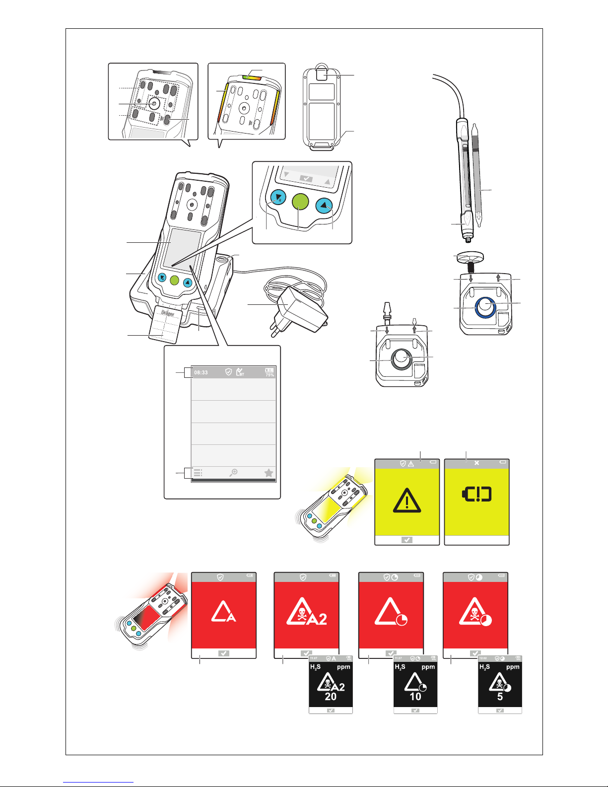
Graphic A
1 Display 4 Charge LED green/red
2 Locking screw for an additional
charging module
5 Labelling field (X-am 8000 only)
3 Power supply unit 6 Induction charger
Graphic B
1 Gas inlets 3 Horn
2 Thread port for pumps and calibra-
tion adapter
4 Pump outlet and inlet
Graphic C
1 LED green/yellow/red 2 LED yellow/red
Graphic D
1 feature button 1 3 feature button 3
2 feature button 2
Graphic E
1 Status information 2 Navigation bar
Graphic F
1 Clip (optional) 2 Socket for support belt for shoulder
version
(X-am 8000 only)
Graphic G
1 Alarm A1 3 STEL alarm
2Alarm A2 4TWA alarm
Graphic J
1 Battery pre-alarm 2 Battery main alarm
Graphic K
1 Calibration adapter (grey coloured
ring)
3 Exhaust
2 Gas inlet 4 Locking screw
Graphic L
1 Pre-tube bracket (X-am 8000 only) 2 Pre-tube (X-am 8000 only)
Graphic M
1 Pump adapter (blue coloured ring) 4 Exhaust
2 Gas inlet 5 Locking screw
3 Dust and water filter
Page 14

14 Technical manual | X-am® 3500/8000
Description
3.2 Intended use
Dräger X-am 3500/8000 is a portable gas detector for clearance measurements
and for the continuous monitoring of the concentration of several gases in ambient
air in the workplace and in explosion-hazard areas.
The X-am 3500 allows measuring up to 4 gases in accordance with the
DrägerSensors (XXS O
2, XXS H2S LC, XXS CO LC, XXS NO2, XXS SO2 and
CatEx 125 PR) which are installed. The gas detector can be operated in pump
mode or in diffusion mode.
X-am 8000 can measure up to 7 gasses in accordance with the installed
DrägerSensors (EC, IR, CatEx, PID). The gas detector can be operated in pump
mode (if it is equipped with a pump) or in diffusion mode.
3.3 Limitations on use
The gas detector is not suitable for measuring process gasses.
Operation of the gas detector in the charging cradle in a vehicle is only permitted
under the following conditions:
– Acoustic signalling must be deactivated (with the help of the PC software CC-
Vision).
3.4 Approvals
A copy of the rating plate and the declaration of conformity are provided in the
enclosed supplementary documentation (order no. 90 33 655).
CSA-specific information:
Only the combustible gas portion of this instrument has been tested for measuring
accuracy.
Radio approval (X-am 8000 only):
The information for radio approval can be viewed in the menu. For further
information, see the following chapter: "Opening information", page 24.
3.5 Label
The energy supply label has a mark for a service label. Here, a maximum of one
service label and one year-point label may be attached one on top of the other.
Further labels, conductive labels or labels with conductive material or parts can
have a negative effect on inductive charging.
The rating plate on the gas detector must not be concealed.
3.6 Sensor slot positions X-am 3500
Sensor slot Configuration
HPP 1 not assigned
HPP 2 CatEx sensor
EC 1-3 EC sensors
Page 15

Technical manual | X-am® 3500/8000 15
Description
3.7 Sensor slot positions X-am 8000
3.8 Further device options for X-am 8000
The following device options are available if needed:
–Pump
– RFID transponder
– Bluetooth
®
module
– Carrying clip
Sensor slot Configuration
HPP 1 PID or IR sensor
HPP 2 IR or CatEx sensor
EC 1-3 EC sensors
Page 16
16 Technical manual | X-am® 3500/8000
Operation
4 Operation
4.1 Operating concept
Navigation is done with the 3 multifeature buttons and the dynamic navigation bar
(see Graphic E on the fold-out page). The navigation bar changes dynamically
depending on the available interactions.
4.2 Symbol explanations
4.2.1 feature buttons
4.2.2 Displays
4.2.3 Application
Symbol Explanation
Confirm action/dialog / return to menu
Confirm all
Scroll up / through display
Scroll down / through display
Cancel action
Display quick menu
Display measuring channels individually
Display all measuring channels
Increase value
Decrease value
Repeat feature
Display menu
Symbol Explanation
Horn and vibration for gas alarm deactivated
Symbol Explanation
Messen
Clearance measurement (X-am 8000 only)
Leak search (X-am 8000 only)
Benzene/pre-tube measurement (X-am 8000 only)
Fresh air adjustment
Bump test or calibration
Page 17
Technical manual | X-am® 3500/8000 17
Operation
4.2.4 Device status
4.2.5 Connection
4.2.6 User level
4.2.7 Display in gas channel
Symbol Explanation
Overview of the bump test intervals activated (additional information for the D-Light feature).
There are no gas alarms or errors.
Monitoring of the calibration intervals activated, D-Light function
deactivated (additional information for the D-Light function).
There are no gas alarms or errors.
Alarm message
Warning message
The gas detector can be operated normally. If the warning message is still displayed after operation, the gas detector requires
maintenance. Menu Messages displays details.
Fault message
The gas detector or measuring channel is not ready to measure
and requires maintenance. Menu Messages displays details.
Information message
Menu Messages displays details.
STEL alarm message
TWA alarm message
Event report
Symbol Explanation
Maintenance mode (access to the device via PC or X-dock)
Bluetooth
®
activated
Bluetooth
®
deactivated
Bluetooth
®
connection established
Symbol Explanation
User level 1
User level 2
User level 3
Symbol Explanation
Bump test or calibration successful
Bump test or calibration failed
Measurement range exceeded
Page 18

18 Technical manual | X-am® 3500/8000
Operation
4.3 Signalling concept
4.3.1 Acoustic operation signal
A periodic acoustic signal indicates that the device is functional. The acoustic
operation signal can be deactivated. For further information, see the following
chapter: "Activating silent mode", page 33
4.3.2 Visual operation signal
A periodic pulse (increasing and decreasing intensity) of the green LED indicates:
– Monitoring, confined space entry, leak search or benzene/pre-tube
measurement application active
– There is no device or channel error, no gas alarm and no special state
4.3.3 Visual operation signal with activated D-Light
An activated D-Light feature allows the user to also check and indicate compliance
with certain settings:
– Evaluation of bump test intervals activated and complied with (factory setting) or
evaluation of the calibration intervals active and complied with
– Usage interval complied with
The D-Light feature can be activated using the Dräger CC-Vision PC software.
Signalling visually corresponds to the operating signal.
If one of the conditions listed is not fulfilled and the D-Light is activated, the greed
LED will switch on briefly at regular intervals (short flash approx. every 60 s) instead
of pulsing periodically.
4.4 Switch the gas detector on or off
4.4.1 Initial start-up
When the gas detector is switched on for the first time, a wizard starts. The wizard
guides the user through the set-up of the gas detector:
– Language selection, if applicable
– Data format and date
–Time
Readings below the measurement range
Channel error
Blocking alarm
##### Value too high to be displayed
Symbol Explanation
Page 19
Technical manual | X-am® 3500/8000 19
Operation
4.4.2 Switching on the gas detector
1. Hold down the OK button for approx. 3 s.
The display shows a countdown.
The switch-on sequence and the warm-up phase of the sensors start.
The following display appear one after the other:
–Start screen
– Software version
– Display test (the display alternates between black and white)
– Alarm element test (LEDs, alarm signal and vibration alarm)
– Customer-specific information screen (optional)
– Alarm thresholds, STEL, TWA (if configured) and LEL factor (if available)
– Any expired bump test or calibration interval as well as early warnings (if
configured)
– Measured value display
After the wizard is complete, a customer-specific information screen (optional and
configurable with the Dräger CC-Vision PC software) and the measured value
display appear. The remaining sensor warm-up time is displayed in the upper, lefthand corner in a yellow box.
WARNING
Incorrect device feature/settings!
Incorrect device features/settings may result in danger to life and/or risk of
explosion.
► Before every use, check whether the display elements, the alarm features and
information are displayed correctly. If one of the items listed above does not
feature correctly or is incorrect, do not use the gas detector and have it
inspected.
The following features are active during the sensor warm-up phase:
– The measured values flash
– The yellow LED is illuminated
– A warning notice is displayed
The gas detector is ready to measure when the measured values no longer flash
and the yellow LED is no longer illuminated. The warning notice may continue to
be displayed if there are warnings pending. To display the warnings, refer to the
technical manual.
No alarms are issued during the warm-up phase!
4.4.3 Switching off the gas detector
1. Hold down ▲ and ▼ simultaneously until the displayed countdown expires.
The visual, acoustic and vibration alarms activate briefly.
The gas detector is switched off.
Or
1. Select in measuring mode and confirm the dialog.
Page 20
20 Technical manual | X-am® 3500/8000
Operation
2. Select and confirm Switch off.
The gas detector may only be switched off without a prior sign-on if the Switch-
off allowed feature is activated using the Dräger CC-Vision PC software. Factory
setting: activated
When the gas detector is placed in the charging cradle, it switches off
automatically.
If the gas detector remains off for longer than 21 days and is not charged, deep
sleep mode is activated. In deep sleep mode, the gas detector can no longer be
switched on using the Dräger CC-Vision PC software or the Dräger X-dock. In this
case, the gas detector must be switched on manually.
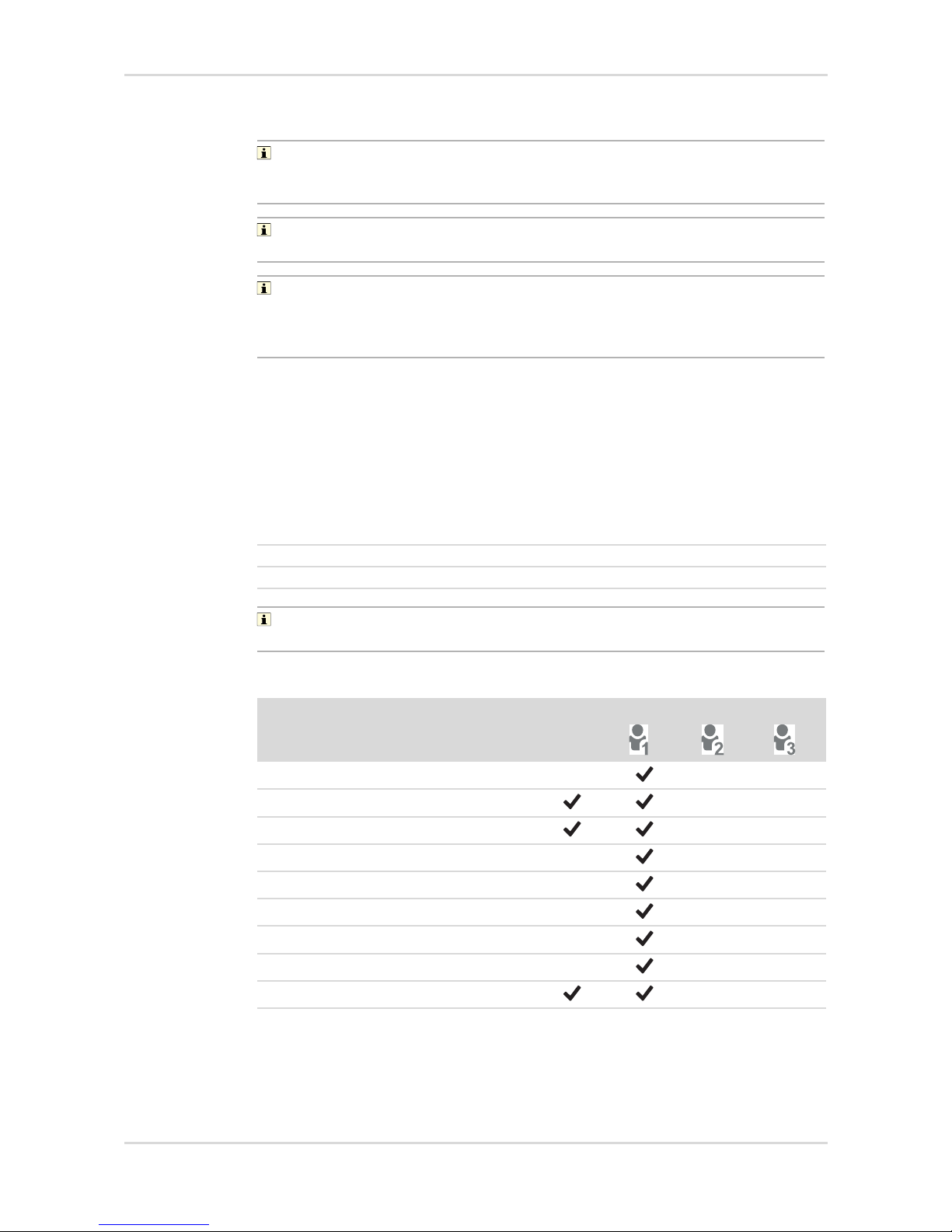
4.5 Logging a user in or out
The gas detector has four configurable user levels. The user levels can be set using
the Dräger CC-Vision PC software. User level 0 means that the user is not signed
on. User levels 1 to 3 require a password for sign-on.
The following passwords are created by default:
Dräger recommends changing the predefined passwords after initial
commissioning.
Default setting:
User level 1: 0001
User level 2: 0002
User level 3: 0003
Function User level
0
Bump test
---
Fresh air adjustment
--
Clearance measurement
1)
1) X-am 8000 only
--
Leak search
1)
---
Benzene/pre-tube measurement
1)
---
Settings menu
---
Maintenance menu
---
Change measurement gas
1)2)
2) The data stored in the statistics counters are lost when the measurement gas is changed. The
Dräger GasVision PC software can be used to manually view the data via the data logger at a
later point in time. Automatic notifications via the X-dock Manager may only be available to a
limited extent.
---
Bluetooth
®1)
--
Page 21
Technical manual | X-am® 3500/8000 21
Operation
To log in a user:
1. Select in measuring mode and confirm the dialog.
2. Select and confirm Login.
3. Enter the four-digit user level password and confirm each digit.
To sign out a user:
1. Select in measuring mode and confirm the dialog.
2. Select ‘Sign out’ and confirm the dialog.
4.6 Preparations for operation
WARNING
Serious damage to health!
An incorrect calibration can lead to incorrect measured values, which may result in
serious damage to health.
► Before performing safety measurements, check the calibration by way of a bump
test, adjust as necessary, and check all alarm elements. If national regulations
exist, the bump test must be performed in accordance with these regulations.
WARNING
Risk of explosion
Only applicable if using the Dräger CSE Connect app:
The use of an unsuitable smartphone or accessories may lead to ignition of
flammable or explosive atmospheres.
► The smartphone on which CSE Connect is installed must be suitable and
approved for use in areas subject to explosion hazards.
► A list of compatible smartphones is available from Dräger.
► Use only accessories that are suitable for use in areas subject to explosion
hazards.
1. Switch on the gas detector. The current measured values are shown in the
display.
2. Observe warnings, error messages and special states.
3. Verify that the gas inlet openings and membranes are clean, freely accessible,
dry and undamaged.
4. Check that the date and time are set correctly.
4.7 During operation
WARNING
Danger to life and/or risk of explosion!
The following alarms indicate a danger to life and/or risk of explosion:
– A2 alarm
– STEL or TWA alarm
– Device/channel error
► Immediately leave the hazard area.
Page 22
22 Technical manual | X-am® 3500/8000
Operation
WARNING
Incorrect measured values!
Only for diffusion mode: If water seals the gas inlets on the gas detector (e.g. in
heavy rain or if the gas detector is submerged in water), incorrect measured values
may be returned.
► With the display facing downward, shake the gas detector to remove the water.
CAUTION
High readings outside of the LEL display range or a blocking alarm may indicate an
explosive concentration.
If the concentrations of combustible materials are too high, this may be the result of
a lack of O
2.
4.7.1 Monitoring measuring mode
In normal measuring mode, the measured values are displayed for every
measurement gas (see Graphic E on the fold-out page). The operation signal
sounds at regular interval (configurable), and the green LED pulses (e.g. visual
operation signal or D-light feature).
If a measuring range is exceeded or not reached, the respective symbol is
displayed instead of the measured value. For further information, see the following
chapter: "Symbol explanations", page 16
If, in measuring mode, a event (e.g. an alarm) occurs, the respective symbol is
displayed in the status bar (after the event is acknowledged, if necessary).
4.7.1.1 Displaying the measuring channel
To display an individual measuring channel:
1. Select in measuring mode.
2. Use ▲ or ▼ to view the individual measuring channels.
3. Select to navigate to the measuring channel overview.
4.7.1.2 Opening the event report
The following events are counted and displayed: A1/A2, STEL, shocks, incorrect
password entries.
If the gas detector is switched off and then on again, the event report is deleted.
To open the event report:
1. Select > Info > Device information in measuring mode.
2. Use ▲ or ▼ to scroll through the individual pages until the event report.
The symbol indicates a failed sign-on only after 5 attempts.
Page 23

Technical manual | X-am® 3500/8000 23
Operation
4.7.1.3 Activating the pump
To activate the pump in (normal) measuring mode:
1. Place, align and tighten the pump adapter on the thread port on the top cover.
Check that the pump adapter is mounted correctly. Avoid bending the pump
adapter. The gas detector automatically switches to pump mode as soon as the
pump adapter is mounted.
The leak test starts automatically.
2. When the leak test is displayed, the suction inlet on the probe or hose closes
within 60 s and remains closed until the leak test is complete.
3. Release the inlet opening.
● Leak test successful: Measurement starts.
● Leak test failed: Inspect the accessories and the pump adapter and then
repeat the leak test.
4. Observe the flushing times. For further information, see the following chapter:
"Special features when measuring with the pump", page 25
4.7.2 Alarms
In the event of an alarm, corresponding displays, the optical alarm, vibration alarm
as well as, if necessary, the acoustic alarm are activated (configurable). For further
information, see the following chapter: "Alarm settings", page 69
To acknowledge an alarm:
1. Select .
4.7.3 Special state
The operation signal is deactivated during a special state. Special states are
displayed by the following visual signals:
– Yellow LED flashing – ‘warm-up 1’ special state
– Yellow LED continuously illuminated – general special state
No alarms are issued during a special state.
Exception: The calibration adapter is mounted in measuring mode. In this case,
alarms continued to be issued as long as the measurement gas can reach the
sensors.
WARNING
Incorrect measurement!
A mounted calibration adapter blocks free gas diffusion to the sensors. Correct
measured values and alarms can no longer be guaranteed.
► It is imperative to actively bump the sensors (e.g. test gas cylinder with pressure
reducer, flow 0.5 L/min).
4.7.4 Blocking alarm
The blocking alarm protects the CatEx sensor.
Page 24

24 Technical manual | X-am® 3500/8000
Operation
If the measuring range is exceeded significantly at the CatEx channel (very high
concentration of flammable materials), a blocking alarm is triggered. This CatEx
blocking alarm can be acknowledge by switching the gas detector off and then on
again in fresh air.
X-am 8000 only: This does not apply in the case of an activated over range for
methane.
4.7.5 Deleting (application) peaks
1. Select in measuring mode.
2. Select Clear app. peak and confirm the dialog.
The function must be activated in the quick menu. Alternatively, this function can
also be called via the menu.
4.8 Calling the Quick Menu
The Dräger CC-Vision software can be used to save up to 6 preferred features.
The following features are default settings:
– Device information
– Switch between day and night mode
– Display messages
– Display shift peaks
– Display application peaks
– Delete application peaks
To open the quick menu:
1. Select in measuring mode.
2. Select and confirm the desired feature.
4.9 Opening information
1. Select > Info in measuring mode.
The following options are available:
Option Description
Messages The pending warnings and errors are
displayed.
Device information Device information and information
about the Bluetooth® module (optional,
X-am 8000 only) is displayed (e.g. MAC
address, serial number, firmware version etc.).
Page 25

Technical manual | X-am® 3500/8000 25
Operation
4.10 Measuring
4.10.1 Special features when measuring with the pump
NOTICE
Magnetic media may be damaged!
The pump adapter and calibration adapter contain a magnet which may delete data
from a magnetic stripe.
► Do not bring magnetic media (e.g. credit cards) into close proximity to the pump
adapter or calibration adapter.
– Use the dust and water separators when taking measurements with the pump.
– Following a bump test with aggressive gases (such as biogas or chlorine), flush
the pump with clean air for several minutes to extend the service life of the
pump.
Gas statistics The following gas statistics are avail-
able:
–Select Shift peak to display the
exposure peaks for all gasses.
–Select Application peak to display
the application peaks for all gasses.
–Select TWA values to display the
available TWA values for all gasses.
–Select STEL values to display the
available STEL values for all gasses.
Intervals The following intervals are available:
– Select the bump test interval (Bump
test interval) to display the days
remaining until the next bump test for
all channels. For details, select and
confirm the respective channel.
–Select Calibration interval to dis-
play the days remaining until the next
calibration for all channels. For
details, select and confirm the
respective channel.
–Select Life time to display the
remaining life time.
Capture ranges Capture ranges are displayed.
Battery The battery state of charge is displayed
(large).
Approvals
(X-am 8000 only with the Bluetooth®
module)
Approval information is displayed (eLabel).
Option Description
Page 26

26 Technical manual | X-am® 3500/8000
Operation
The wizards are only available for X-am 8000.
For the DrägerSensors XXS CI2, COCI2, O3 as well as amine and odorants, there
are no wizards for confined spaces and leak searching, as these materials can not
be pumped (properly) through tubes. In addition to the materials listed above, there
may also be other materials for which there are no flushing times available in the
gas detector. There is no confined space entry wizard for these materials.
Flush the Dräger sampling hose or Dräger probes prior to each measurement with
the gas to be measured. The flushing phase is necessary to reduce negative effects
associated with the use of a sampling hose or a probe, e.g. gas transport time,
memory effects, dead volume. The duration of the flushing phase depends on
factors such as type and concentration of the gas or vapour to be measured as well
as material, length, diameter and age of the sampling hose or probe. In addition to
the flushing time, the sensor response time must be observed (refer to the
instructions for use for the DrägerSensors used).
Generally, when using a sampling hose (3 mm internal diameter, new, dry, clean)
with standard gasses, a typical flushing time of approx. 3 s/m is required.
Example:
The flushing time for oxygen with a 10 m hose is approx. 30 seconds. The assumed
sensor response time is approx. 10 seconds in addition. Thus, the overall time
before reading the gas detector is approx. 40 seconds.
A flow-rate alarm is delayed by 10 to 30 seconds depending on the length of the
hose.
X-am 8000: For benzene/pre-tube measurements, the maximum hose length is
10 m.
4.10.2 Carrying out measuring with the pump
Requirements:
– The gas detector is equipped with a pump and is switched on.
– All installed sensors are warmed up.
– The gas detector is ready to take measurements.
– The thread port for the pump adapter and calibration adapter must be clean.
1. Connect the hose (3 mm internal diameter) with the dust and water filter to the
inlet spout (see figure M on page 3) of the pump adapter.
Page 27

Technical manual | X-am® 3500/8000 27
Operation
2. Mount the pump adapter to the gas detector. Make sure that both guide pins are
in the correct grooves.
Check that the pump adapter is mounted correctly. If the pump adapter is
mounted correctly, the leak test starts automatically. If the leak test does not
start, the gas detector is not ready for use. Avoid bending the pump adapter.
The gas detector automatically switches to pump mode as soon as the pump
adapter is mounted.
The leak test starts automatically.
3. When the leak test is displayed, the suction inlet on the probe or hose closes
within 60 s and remains closed until the leak test is complete.
4. Open the suction inlet.
– Leak test successful: Measuring starts. Observe the purging times!
– Leak test failed: Inspect the probe, hose and adapter and repeat the leak
test.
5. Place the probe or the end of the hose on the sampling location.
The temperature at the measurement location may deviate from the temperature
in the gas detector, which may influence the measured value display. The correct
functioning of the temperature correction can only be guaranteed on the gas
detector.
To stop measuring with the pump:
1. Loosen the screw on the pump adapter.
34964
!
Page 28

28 Technical manual | X-am® 3500/8000
Operation
2. Remove the pump adapter.
✓ The pump is flushed and the gas detector automatically switches to diffusion
mode.
4.11 Measurements with wizards
The gas detector has wizards for easily preparing the measurements and for
measurement displays optimised for the measurement.
There are wizards for the following applications:
– Confined space entry: for measuring with a probe/hose, e.g. In a container
– Leak search: for detecting gas leaks
– Benzene/pre-tube measurement: for using pre-tubes as a filter for the PID
While the wizard loads, the gas detector is in a special state.
The wizards are not supported if the gas detector does not have the required
material-specific properties for the gas to be measured, or if the gas detector is not
within the permissible temperature range (typically 0 to 40 °C for confined spaces
and benzene/pre-tube measurements).
4.12 Carrying out confined space entry measurements with
the wizard
During confined space entry measurements, the duration of the measurement (in
mm:ss) is displayed for a maximum of one hour in place of the time. Afterwards, the
time is displayed again. The measurement duration is restarted after each flow
alarm.
Requirements:
– The gas detector is switched on.
– The user is signed in with the corresponding user level.
To carry out a confined space entry measurement:
1. Sign in with the required user level, if necessary.
2. Select > Confined Space in measuring mode (if configured using the Dräger
CC-Vision PC software). Follow the directions of the wizard.
The hose length or probe selection is displayed.
3. Select the hose length / probe.
The leak test starts.
4. Confirm the successful leak test.
The start dialog for the measurement is displayed.
5. Place the probe or the hose on the sampling location.
6. Confirm the dialog to start the measurement.
The hose is flushed, and the remaining flushing time is displayed. If, during the
flushing time, an alarm threshold is or the permissible temperature range is
exceeded, the countdown is stopped, the alarm or message is displayed and the
special state is exited.
Page 29

Technical manual | X-am® 3500/8000 29
Operation
The displayed flushing time shows the minimum wait time required for the
measurement gas to reach the sensor from the sampling location in an ideal
scenario. This applies to the use of a Dräger sampling hose (fluoroelastomer,
brand new, dry, clean) with an internal diameter of 3 mm. Other fixtures (e.g.
pre-tube) extend the minimum wait time and must also be taken into
consideration. The flushing time only applies to the configured measurement
gas.
The flushing times recommended by the gas detector are ascertained according
to the state of technology. Dräger is not liable for their use. The user is responsible
for evaluating the wait time for their application. After the wait time expires,
evaluation is required to determine if the measured value is stable or if the wait time
was possibly insufficient. The same applies if the countdown was stopped
unexpectedly.
The measurement of other gasses or vapours than the selected measurement
gas per measuring channel causes additional wait time which must also be
considered in addition to the minimum wait time.
The confined space entry measurement is displayed when after the flushing time
is complete.
To end the confined space entry measurement:
1. Select during the confined space entry measurement and confirm the dialog.
A dialog for performing another confined space entry measurement is
displayed.
2. Select to end the wizard.
3. Remove the pump adapter.
4. Return to normal measuring mode.
4.13 Carrying out leak searches with the wizard
During a leak search, the duration of the measurement (in mm:ss) is displayed for a
maximum of one hour in place of the time and the measured values can be
displayed in the form of a bar chart (configurable with the CC-Vision PC software).
Afterwards, the time is displayed again. The measurement duration is restarted
after each flow alarm.
During a leak search, the Clear app. peak feature should be stored in the quick
menu using the Dräger CC-Vision PC software. This feature can be used to delete
the application values in the bar chart.
Because of the physical flushing times, Dräger recommends carrying out
measurements with the leak search wizard without a hose/probe or with only a
short hose (max. 2 m).
Requirements:
– The gas detector is equipped with a pump and is switched on.
– All installed sensors are warmed up.
– The gas detector is ready to take measurements.
Page 30

30 Technical manual | X-am® 3500/8000
Operation
To carry out a leak search:
1. Sign in with the required user level.
2. Select > Leak Search in measuring mode.
3. Confirm the successful leak test to start the measurement.
The device emits tones in the “Individual measuring channel” display which
increase in frequency as the gas concentration increases. If the pre-alarm threshold
is reached, the gas alarm appears.
To end the leak search:
1. Select in leak search mode and confirm the dialog.
2. Remove the pump adapter.
3. Return to normal measuring mode.
4.14 Carrying out a benzene/pre-tube measurement with the
wizard
Observe the instructions for use of the respective tube!
The use of a pre-tube is only possible when using the wizard.
During the benzene/pre-tube measurement, the visual alarm, acoustic alarm,
vibration alarm and alarm evaluation are deactivated.
A benzene/pre-tube measurement (photoionisation detector) with a pre-tube (e.g.
benzene pre-tube) can only be done with the benzene/pre-tube wizard.
During the benzene/pre-tube measurement, the gas to be measured and the PEAK
values are visible on the display. All other sensors are not evaluated.
4.14.1 Mounting the pre-tube bracket
Fast temperature and humidity changes influence the measured signal. If
temperature and humidity jumps are anticipated, Dräger recommends using a
damp pre-tube for the measurement.
Page 31

Technical manual | X-am® 3500/8000 31
Operation
1. Mount the pump adapter to the gas detector. Make sure that both guide pins are
in the correct grooves.
2. Connect the dust and water filter (3) to the short hose piece (4) on the pump
adapter (5).
3. Mount the pre-tube bracket (2) to the dust and water filter (3).
4. Mount the hose or bar probe (1) to the pre-tube bracket (2) (max. hose length:
10 m).
5. As necessary: Use a floating probe.
3496434965
!
1
2
5
3
4
Page 32

32 Technical manual | X-am® 3500/8000
Operation
Use an adapter piece for varying hose diameters if necessary (minimum internal
diameter: 3 mm).
4.14.2 Making measurement
Use a new pre-tube for each individual measurement with a pre-tube.
Requirements:
– The gas detector is switched on.
– The user is signed in with the corresponding user level.
– Warm-up phase 1 of the PID is complete.
– The pre-tube bracket and the dust and water filter are mounted on the pump
adapter.
To carry out a benzene/pre-tube measurement:
1. Select > Benzene / Pre-tube in measuring mode (if configured using the
Dräger CC-Vision PC software).
A dialog for performing the fresh air calibration is displayed.
2. Carry out a fresh air calibration with an activated charcoal tube or skip this step
by pressing .
3. When selecting the fresh air calibration:
4. Follow the directions of the wizard.
5. After a successful fresh air calibration, remove the activated charcoal tube.
6. The pre-tube selection is displayed.
7. Select the pre-tube.
If a benzene pre-tube is selected, the PID automatically switches to benzene.
8. Open the pre-tube, insert it in the pre-tube bracket (arrow marking in the
direction of the gas detector; see figure L on page 3) and confirm the dialog.
The hose length selection is displayed.
9. Select the hose length or probe.
The leak test starts.
10.Confirm the successful leak test.
The start dialog for the measurement is displayed.
11. Place the probe or the end of the hose on the sampling location.
12.Select to start the measurement.
The hose is flushed, and the remaining flushing time is displayed.
The benzene/pre-tube measuring mode is displayed after the flushing time is
complete.
To end the benzene/pre-tube measurement:
1. Select in benzene/pre-tube measuring mode and confirm the dialog.
A dialog for removing the pre-tube appears.
2. Remove the pre-tube.
A dialog for a further benzene/pre-tube measurement appears.
3. Select to end the benzene/pre-tube measurement.
4. Remove the pump adapter with the pre-tube bracket if necessary.
Page 33

Technical manual | X-am® 3500/8000 33
Operation
4.15 Configuring the device settings
Briefly press and simultaneously to navigate to Monitoring.
To open the device settings:
1. Select in measuring mode and confirm the dialog.
2. Sign in with the required user level, if necessary.
3. Select and confirm Settings.
4.15.1 Activating day or night mode
1. Open the device settings.
2. Select and confirm Night mode / Day mode.
4.15.2 Changing the device language
1. Open the device settings.
2. Select Changing language....
3. Select and confirm the desired language.
4.15.3 Setting the date and time
1. Open the device settings.
2. Select Date & Time.
3. Select Set date format and then select and confirm the date format.
4. Select Set date and then set and confirm the date.
5. Select Set time and then set and confirm the time.
The user must manually switch between summer and winter time.
When using the X-dock maintenance station, automatic time synchronisation is
possible.
4.15.4 Activating silent mode
Silent mode can be activated for 15 minutes on the gas detector. When silent mode
is active, vibration and the horn are deactivated. Permanent deactivation is possible
using the Dräger CC-Vision PC software.
Silent mode may not be permanently activated for applications according to ATEX.
4.15.5 Activating or deactivating the capture range
1. Open the device settings.
2. Select Capture ranges.
3. Activate or deactivate the capture range.
Dräger recommends that you activate the capture ranges function.
Page 34

34 Technical manual | X-am® 3500/8000
Operation
4.15.6 Activating or deactivating Bluetooth® (X-am 8000 only)
1. Open the device settings.
2. Select Bluetooth.
3. Activate or deactivate Bluetooth
®
.
4.16 Activating an automatic over range
An automatic over range can only be activated for the sensors DrägerSensor CatEx
125 PR (order number 68 12 950) and CatEx 125 PR Gas (order number
68 13 080) with the measurement gas methane.
Prerequisite:
– The measuring ranges %LEL (heat of reaction) and vol. % (thermal
conductions) are calibrated.
1. The automatic over range can only be activated with the Dräger CC-Vision PC
software.
WARNING
Risk of explosion!
Only for CatEx sensors: The automatic over range only applies for methane in the
air. Any other gas composition has an impact on the measured signal, may cause
an incorrect display of the results and may cause permanent damage to the sensor.
► Only use the automatic over range to measure methane in the air.
When the automatic over range is activated, the device automatically switches to
the vol. % range if the 100 %LEL methane range is exceeded.
When the values return to the <100 %LEL methane range, the measured value
display alternates with the transitional phase indicator (circle arrow).
4.17 Hydrogen (H2) added signal (for IR Ex)
The H2 added signal can be adjusted using the Dräger CC-Vision PC software.
Requirements:
– At least one DrägerSensor XXS H
2 HC (68 12 025) is activated. H2 is set as the
measurement gas.
– An Ex channel on the DrägerSensor DUAL IR Ex/CO
2 (6811960) or
DrägerSensor IR Ex (68 12 180) is activated.
– Both channels are set to the unit %LEL/%LEL/%LIE.
–The H
2 added signal is only possible with a DrägerSensor XXS H2 HC and an
IR Ex channel.
When the H
2 added signal is activated, the LEL gas concentrations of both selected
sensors are added together and the result is shown in the display in the place of the
IR Ex display.
An activated H
2 added signal is displayed with a + next to the gas name of the
IR Ex sensor in the display.
Page 35

Technical manual | X-am® 3500/8000 35
Operation
Previously set alarm thresholds are maintained in order to ensure that in the
presence of hydrogen (H
2) the alarm of the IR Ex Channel is triggered earlier if
required.
Page 36

36 Technical manual | X-am® 3500/8000
Troubleshooting
5 Troubleshooting
If the following remedial measures are unsuccessful, contact DrägerService.
5.1 Error
Error Cause Remedy
Life time expired Life time of the gas detec-
tor expired
Reconfigure the life time
with the Dräger CC-Vision
PC software.
Device locked Gas detector locked by X-
dock
Unlock the gas detector
with X-dock or the X-dock
manger.
Bump test interval
expired
Bump test interval expired Carry out bump test.
Calibration expired Calibration interval expired Carry out the span calibra-
tion.
Hardware error An internal fault has been
detected.
Switch the instrument off
then on again, or remove
and reconnect the battery.
Pressure too low Ambient pressure below
the minimum range
Check the ambient pressure and restore the
device to a permissible
range.
Pressure too high Ambient pressure above
the maximum range
2 adapters identified More than one magnetic
sensor detected
Remove the faulty magnetic fields.
LED failure Failed alarm element test
with X-dock: Alarm lamp
Repeat the alarm element
test with X-dock.
Horn failure Failed alarm element test
with X-dock: Alarm horn
Repeat the alarm element
test with X-dock.
Vibrator failure Alarm element test result
with X-dock: Vibration
motor faulty
Repeat the alarm element
test with X-dock.
Alarm test failed Alarm test with X-dock
failed
Repeat the alarm test with
X-dock.
Battery com. error Data connection to battery
interrupted. (Screws may
not be tightened properly)
Re-mount the battery.
Bump test failed Bump test failed Carry out a bump test or a
span calibration
Zero calibration failed Zero-point calibration
failed
Carry out a zero-point
adjustment
Span calibration failed Span calibration failed Carry out a span calibra-
tion
Capturing is on Response time test with X-
dock failed
Repeat the response time
test with X-dock.
Page 37

Technical manual | X-am® 3500/8000 37
Troubleshooting
5.2 Warnings
Oxygen deficiency Insufficient oxygen for the
correct functionality of the
CatEx sensor
Operate the gas detector
in atmospheric conditions.
Value negative Measured value in nega-
tive range
Carry out a fresh air calibration / zero-point calibration
Sensor missing Sensor faulty or not con-
nected
Connect sensor or check
contacts
Span calibration compensation channel failed
Failed span calibration of
the horizontal electrode
Carry out a span calibration for the horizontal electrode
SDS parameter error
1)
IR sensor error detected. Switch the device off and
then on again; exchange
the IR sensor.
Sensor subsystem
error
1)
IR sensor error detected:
IR-sensor reports an error
IR sensor peak
1)
IR sensor error detected:
IR signal quality
Error acknowledges itself
automatically if the error
condition is no longer
present.
Overrange after warm-up 1Overgassing detected on
CatEx sensor immediately
after warm-up 1
Carry out a zero-point
adjustment
CatEx contaminated CatEx sensor poisoning Exchange the CatEx sen-
sor
Invalid part no. Sensor part number
invalid or not supported.
Check the sensor date
(inauguration code); use
the current sensor or
update the firmware.
No pump installed The pump adapter is con-
nected, but he pump is not
usable (or not available)
Remove the pump adapter
from the device
Pump flow range Contact Dräger service
Pump error Exchange the pump
Pump flow too low Inspect the pump adapter,
hose and hose connections
1) X-am 8000 only
Error Cause Remedy
Warnings Cause Remedy
Life time expires soon Life time of the device
expires soon
Reconfigure the life time
with the Dräger CC-Vision
PC software.
Bump test interval
expires soon
Bump test interval expires
soon
Perform bump test
Bump test interval
expired
Bump test interval expired Perform bump test
Page 38

38 Technical manual | X-am® 3500/8000
Troubleshooting
Calibration expires soon Calibration interval expires
soon
Carry out a span calibration
Calibration expired Calibration interval of the
(compensation)channel
expired
Carry out a span calibration
Logger almost full Data logger memory 90 %
full
Read out the data memory
(with the GasVision PC
software) and/or delete it.
Or switch to “overwrite”.
Logger full Data logger memory 100%
full
Temperature too high Ambient temperature too
high.
Reduce the ambient temperature; calibrate the
sensor.
Temperature too low Ambient temperature too
low.
Increase the ambient temperature; calibrate the
sensor.
Pressure too high Pressure above the maxi-
mum range
Lower the ambient pressure
Pressure too low Pressure below the mini-
mum range
Increase the ambient pressure
Battery too hot Battery sub-system too hot Reduce the ambient tem-
perature
Battery too cold Battery sub-system too
cold
Increase the ambient temperature
Battery com. error Data connection to battery
interrupted. (Screws may
not be tightened properly)
Re-mount the battery
Peak detected
1)
IR sensor error detected:
IR signal quality
Switch the device off and
then on again; exchange
the IR sensor.
Warm-up 1 Device not yet measure-
ment-ready
Wait until warm-up time 1
is complete
Warm-up 2 The warm-up time of the
sensors varies depending
on the ambient conditions.
Wait until warm-up time 2
is complete (e.g. required
before calibration can be
carried out)
CatEx protection CatEx sensor blocking
alarm caused by overgassing
Switch the device off and
then on in fresh air
Value negative Measured value in nega-
tive range
Carry out a fresh air calibration / zero-point calibration.
Pump error Replace the pump.
1) X-am 8000 only
Warnings Cause Remedy
Page 39

Technical manual | X-am® 3500/8000 39
Maintenance
6 Maintenance
WARNING
Risk of explosion!
To reduce the risk of ignition of a flammable or explosive atmosphere, observe the
following:
► Do not open the gas detector in explosion-hazard areas.
WARNING
Danger to health!
Test gas may damage health if inhaled.
► Do not inhale the test gas. Observe the hazard warnings of the relevant Safety
Data Sheets and the instructions for use of the gas detector! Observe the
national regulations when defining calibration intervals.
6.1 Maintenance intervals
For inspections and maintenance, see:
– EN 60079-29-2 – Guidelines for selection, installation, use and maintenance of
instruments for the detection and measurement of flammable gases and oxygen
– EN 45544-4 – Electrical apparatus used for the direct detection and direct
concentration measurement of toxic gases and vapours – Part 4: Guide for
selection, installation, use and maintenance
– National regulations
6.2 Calibration intervals
Observe the relevant specifications in the Sensor Handbook or in the instructions
for use/data sheets of the DrägerSensors installed.
Recommended calibration intervals for DrägerSensors:
Tes t Interval
Inspection and maintenance by specialists.
Every 12 months
DrägerSensor Calibration interval
CatEx, O
2, H2S, H2S LC, CO LC, SO2,
NO
2
Every 6 months
IR Ex/CO
2 Every 12 months
PID HC, PID LC ppb Depending on the application condi-
tions, daily calibration may be necessary. The interval can be extended littleby-little to 30 days if there are no calibration deviations on consecutive
inspections.
Other DrägerSensors See the special data sheets for the
respective sensors.
Page 40

40 Technical manual | X-am® 3500/8000
Maintenance
6.3 Perform bump test
The bump test can be performed as follows:
– Bump test with the wizard (quick bump test)
– Bump test with X-dock (quick or extended bump test)
Dräger recommends using the extended bump test for cross calibrations (Dräger
X-dock instructions for use).
X-am 8000: If the gas detection instrument is equipped with a PID sensor, Dräger
recommends not to use the Nonane tester (order no. 83 25 61) for the bump test
because of the long saturation time of the PID sensor.
6.3.1 Carrying out bump tests with the wizard
WARNING
Incorrect alarm behaviour!
A closed gas path causes incorrect measured values. This may cause alarms to be
triggered incorrectly.
► Never close the outlet of the calibration adapter.
Dräger recommends a test gas concentration of <60 %LEL for CatEx and IR
sensors and a measuring range of 0 % to 100 %LEL.
For bump tests with the wizard and the X-dock, the results are saved in the device
memory.
Requirements:
– A bump test can only be carried out if at least one sensor has been configured
for the bump test with the Dräger CC-Vision PC software.
– The gas detector is switched on and warm-up phase 1 is complete.
– The thread port for the pump adapter and calibration adapter must be clean.
– A suitable test gas cylinder is available, e.g. a test gas cylinder (order number
68 11 130) with the following mixed gas ratios: 50 ppm CO, 15 ppm H
2S,
2,5 vol. % CH4, 18 vol. % O
2
Other test gas cylinder can be added upon request.
Page 41

Technical manual | X-am® 3500/8000 41
Maintenance
To perform a bump test:
1. Mount the calibration adapter to the gas detector. Make sure that both guide
pins are in the correct grooves.
2. Connect the hose to the test gas cylinder and the inlet on the calibration adapter.
3. If needed, connect a second hose (max. length: 2 m) to the outlet on the
calibration adapter to direct the test gas to an exhaust or outside. Make sure that
these is sufficient ventilation in room or vehicles.
4. Open the bump test (depending on the configuration).
a. Select > Maintenance > Bump test (if configured using the Dräger CC-
Vision PC software).
b. > Login
Enter and confirm the password.
Select Maintenance > Bump test.
5. Open the valve on the test gas cylinder, the volume flow must be 0.5 /min and
the gas concentration must be higher (lower with oxygen) than the alarm
threshold concentration that is to be tested.
6. Select to start the bump test.
All measuring channels which are included in the bump test flash, and all
others are greyed out. When a measuring channel successfully passes the
test, appears.
7. The bump test is complete when all measuring channels included in the test
successfully passed or failed the test.
8. Close the valves on the test gas cylinder.
● Select and then confirm the dialog to discard the result.
● Select to confirm the result.
34964
!
Page 42

42 Technical manual | X-am® 3500/8000
Maintenance
9. Remove the calibration adapter.
If there was an error during the bump test:
1. An error is displayed for the measuring channel.
2. Repeat the bump test.
3. If necessary, replace the sensor.
6.4 Calibrate the gas detector
WARNING
Incorrect measured values!
An incorrect calibration may prevent alarms from triggering, or alarms may trigger
late.
► Do not close the outlet of the calibration adapter / exhaust gas hose.
► Always carry out the fresh air / zero adjustment before the span calibration.
NOTICE
Damage to the sensors!
When using the exhaust gas hose, the sensors may be damaged in the case of
direct suction on the exhaust gas hose.
► If necessary, lead the exhaust gas hose (max. length 2 m) to an exhaust of
outside.
Adjustment may not be possible due to instrument and channel errors.
6.4.1 Carrying out a fresh air calibration
To improve accuracy, a fresh air calibration must be carried out if there is a zero
deviation.
Observe the following notices for the calibration:
● For calibrating the XXS O
2 with fresh air, set the display to 20.9 Vol%.
● There may be deviations of >10 % of the measured value for temperatures
below –20 °C if the respective sensor is calibrated at room temperature. Dräger
recommends calibrating the sensor at the planned operating temperature if the
measurement is to be carried out at very low temperatures. This allows a
possible deviation to be reduced.
X-am 8000:
● An activated H
2 added signal is automatically deactivated duration of a bump
test or a calibration.
● During fresh air calibrations, the zero-point of all sensors (except the
DrägerSensors XXS O
2, DUAL IR CO2 and IR CO2, XXS O3) is set to 0.
● The DrägerSensors DUAL IR CO
2, IR CO2 and XXS O3 must be calibrated with
a suitable gas which is free of carbon dioxide / ozone (e.g. N
2).
● The DrägerSensor PID LC ppb can be calibrated with the zero gasses nitrogen
or synthetic air.
Page 43

Technical manual | X-am® 3500/8000 43
Maintenance
Requirements:
– Fresh air calibration can only be carried out if at least one sensor supports the
fresh air calibration.
– The fresh air must be free of measurement or interfering gasses.
– The gas detector is switched on and warm-up phases 1 and 2 are complete.
To carry out a fresh air calibration:
1. Switch on the gas detector.
2. Open the fresh air calibration (depending on the configuration):
If the fresh air calibration was released for user level 0 by the Dräger CC-Vision
PC software:
● Select > Maintenance > Fresh air cal..
If the fresh air calibration was not released for user level 0 by the Dräger CCVision PC software:
a. > Login
b. Enter and confirm the password.
c. Select Maintenance > Fresh air cal..
3. Select to start the fresh air calibration.
All measuring channels which are included in the fresh air calibration flash,
and all others are greyed out.
The result is displayed as follows for every measuring channel:
fresh air calibration successful.
fresh air calibration failed.
4. If necessary, press to overrule the stability control. In this case, a calibration
happens immediately.
Dräger recommends using the automatic stability control (wait until the gas
detector has automatically carried out the calibration).
The new measured value is displayed for confirmation.
The result is displayed as follows:
fresh air calibration successful.
fresh air calibration failed.
5. The fresh air calibration is complete when all measuring channels included in
the calibration have successfully passed or failed the calibration.
► Select and then confirm the dialog to discard the result.
► Select to confirm the result.
If there was an error during the fresh air calibration:
– Repeat the fresh air calibration.
– If necessary, replace the sensor.
6.4.2 Carrying out a single-gas calibration
For a single-gas calibration, you can choose either the zero-point calibration and
span calibration.
With a zero-point calibration, the zero-point of the selected sensor is set to zero.
With a span calibration, the sensitivity of the selected sensor is set to the defined
value of the test gas used.
Page 44

44 Technical manual | X-am® 3500/8000
Maintenance
X-am 8000 only: When implementing an active over range with the CatEx sensor
(measurement gas: methane), observe chapter 4.16.
Use a standard test gas.
Allowed test gas concentration:
Dräger recommends selecting a test concentration in the middle of the
respective measuring range or close to the expected measuring range.
To carry out a single-gas calibration:
1. Screw the calibration adapter onto the gas detector.
2. Connect the test gas cylinder to the calibration adapter.
3. Connect a second hose (max. length: 2 m) to the second connector on the
calibration adapter to direct the test gas to an exhaust or outside.
4. Switch on the gas detector.
5. Select > Login.
6. Enter and confirm the password.
7. Select Maintenance > Single gas cal..
A dialog for selecting the measuring channel to be calibrated appears.
8. Select the measuring channel.
A dialog for selecting the calibration appears.
9. Select either zero-point calibration or span calibration.
► For a span calibration: Enter and confirm the calibration concentration.
10.Open the valves on the test gas cylinder.
11. Select to start the single-gas calibration or to cancel the calibration.
The measuring channel appears, and the measured value flashes.
As soon as the stability check detects a stable measured value, a calibration
is carried out automatically.
DUAL IR Ex
IR Ex
20 to 100 %LEL
1)2)
/ 5 to 100 vol %
1)2)
1) Depending on the selected data set.
2) Depending on the measuring range and the measuring accuracy.
DUAL IR CO2
IR CO2
0.05 to 5 Vol%
2)
CatEx
40 to 100 %LEL
1)2)
20 to 100 vol %
1)2)
O2 10 to 25 vol.%
CO 20 to 999 ppm
H
2S 5 to 99 ppm
H
2 HC 0.5 to 4.0 vol.%
PID HC 100 ppm iBut
PID LC ppb 5 ppm iBut
Test gas concentration of other gasses:
Refer to the Dräger CC-Vision PC software
Page 45

Technical manual | X-am® 3500/8000 45
Maintenance
12.If necessary, press to overrule the stability control. In this case, a calibration
happens immediately.
The new measured value is displayed for confirmation.
The result is displayed as follows:
single-gas calibration successful.
single-gas calibration failed.
13.The single-gas calibration is complete when measuring channel successfully
passed or failed the single-gas calibration.
► Select and then confirm the dialog to discard the result.
► Select to confirm the result.
14.Close the valves on the test gas cylinder.
If there was an error during the single-gas calibration:
– Repeat the single-gas calibration.
– Inspect the sealing contours and surfaces on the calibration adapter as well as
the front cradle of the housing to make sure they are free of damage. Inspect the
thread port for the calibration adapter.
– If necessary, replace the sensor.For further information, see the following
chapter: "Exchanging, adding or removing a sensor", page 48
6.4.3 Carrying out a multi-gas calibration
All sensors which can be calibrated and are released by the Dräger CC-Vision PC
software are included in the multi-gas calibration.
If no sensors are released, the multi-gas calibration menu item is not available.
With a multi-gas calibration, the sensitivity of the sensors is set to the respective
concentration value of the test gas.
Requirements:
– The gas detector is switched on and warm-up phases 1 and 2 are complete. The
user is signed in with the corresponding user level.
– A suitable test gas cylinder is available.
– The concentration values of the test gas cylinder are sent in the gas detector
using the Dräger CC-Vision PC software.
To carry out a multi-gas calibration:
1. Select > Maintenance > Mixed gas cal..
Page 46

46 Technical manual | X-am® 3500/8000
Maintenance
2. Mount the calibration adapter to the gas detector. Make sure that both guide
pins are in the correct grooves.
3. Connect the test gas cylinder to the calibration adapter.
4. If needed, connect a second hose (max. length: 2 m) to the second outlet on the
calibration adapter to direct the test gas to an exhaust or outside.
5. Open the valves on the test gas cylinder.
6. Select to start the multi-gas calibration.
All measuring channels which are included in the multi-gas calibration flash,
and all others are greyed out.
7. If necessary, press to override the automatic stability check. In this case, a
calibration happens immediately.
The new measured value is displayed for confirmation.
The result is displayed as follows:
Multi-gas calibration successful.
multi-gas calibration failed.
8. The multi-gas calibration is complete when all measuring channels included in
the calibration successfully passed or failed the calibration.
► Select and then confirm the dialog to discard the result.
► Select to confirm the result.
9. Close the valves on the test gas cylinder and remove the calibration adapter.
10.Select to complete the calibration.
The measured values are displayed.
11. Select to return to the menu.
34964
!
Page 47

Technical manual | X-am® 3500/8000 47
Maintenance
If there was an error during the multi-gas calibration:
– Repeat the multi-gas calibration or carry out a single-gas calibration.
– Inspect the sealing contours and surfaces on the calibration adapter as well as
the front cradle of the housing to make sure they are free of damage.
– If necessary, replace the sensor.For further information, see the following
chapter: "Exchanging, adding or removing a sensor", page 48
6.4.4 Carrying out a cross calibration
If the respective gas combination and the sensor are released, an automatic cross
calibration and test can be set with the Dräger CC-Vision PC software.
With the gas-switch wizard in the Dräger CC-Vision PC software, a gas can be
selected for the bump test, the calibration and the measurement gas. This
automatically carries out conversions, omitting the need for these to be done
manually.
The settings are also used by the Dräger X-dock maintenance station.
6.5 Carrying out a signal test
In a signal test, all signalling elements are triggered for one second to test them.
To carry out a signal test:
1. Select in measuring mode and confirm the dialog.
2. Select Maintenance > Signaling test.
6.6 Charging the battery
WARNING
Risk of explosion!
To reduce the risk of ignition of a flammable or explosive atmosphere, observe the
following:
► Do not open the gas detector in explosion-hazard areas.
► Only use the LBT 02** (lithium-ion) battery type.
► Do not charge or exchange the battery in explosion-hazard areas.
► Only use the battery charger specified by Dräger. The use of a different charger
nullifies the explosion protection certification of the gas detector.
The battery is a part of the lower part of the casing. The battery can be charged with
or without the gas detector.
1. Place the gas detector or only the lower part of the casing with the battery in the
charging cradle.
The gas detector switches off automatically. The green LED on the power
pack flashes.
The typical charging time after a work shift of 8 – 10 h is approx. 4 h.
The typical charging time for an empty battery is approx. 10 h.
Page 48

48 Technical manual | X-am® 3500/8000
Maintenance
If the specified temperature range (5 to 35 °C) is not reached or is exceeded,
charging stops automatically. This extends the charging time. After a return to the
temperature range, charging continues automatically.
The gas detector can be switched on again in the charging cradle and is then
supplied with electrical current during operation.
WARNING
No measurement!
If there is an external power supply voltage drop > 1 s in the charging tray while the
gas detector is in operation, the gas detector switches off.
► Ensure uninterrupted power supply. If this cannot be insured, check at regular
intervals to make sure that the gas detector is switched on.
6.7 Exchanging, adding or removing a sensor
It is only possible to register sensors in the gas detection instruments X-am
3500/8000 if they are approved for the respective instrument. It is not possible to
change the predefined sensor configuration for the X-am 3500.
Designation and description Order no.
Inductive charging cradle for charging
1 gas detector
83 25 825
Adapter for the plug-in power supply
unit
1)
1) Contact Dräger for availability.
83 25 736
Plug-in power supply unit for charging
1 gas detector
83 16 997
Plug-in power supply unit for charging
5 gas detectors
83 16 994
Plug-in power supply unit 100240 V AC; 1.33 A for charging up to
5 gas detectors
(requires adapter 83 25 736)
83 21 849
Plug-in power supply unit 100240 V AC; 6.25 A for charging up to
20 gas detectors
(requires adapter 83 25 736)
83 21 850
Vehicle connection 12 V / 24 V for
charging 1 gas detector
45 30 057
Vehicle connection 12 V / 24 V for
charging up to 5 gas detectors
(requires adapter 83 25 736)
83 21 855
Vehicle mount
(requires adapter 83 25 736 and vehicle
connection cable 83 21 855)
83 27 636
Page 49

Technical manual | X-am® 3500/8000 49
Maintenance
To add a physical sensor, follow the same procedure used to exchanging a sensor.
However, instead of the a sensor, there is a sensor placeholder in sensor damper.
When the sensor type is exchanges, the sensor damper must also be exchanged
accordingly.
When a sensor is removed from the gas detector and not replaced, a corresponding
sensor placeholder (IR, CatEx, PID, EC) must be inserted in its place.
Equipment:
– Torx T8 screw driver
– Special tool for removing EC sensors
– New sensor
– Sensor damper, if required
– Sensor placeholder, if required
Exchange the sensors using the Dräger CC-Vision PC program (refer to the Dräger
CC-Vision online help). This tests the sensor compatibility and the respective
gasses.
Procedure:
1. Connect the gas detector to a PC. For further information, see the following
chapter: "Connect the gas detector to a PC.", page 66.
2. Start the sensor exchange wizard in the Dräger CC-Vision PC software and
follow the instructions.
3. Open the gas detector. For further information, see the following chapter:
"Opening the gas detector", page 53.
4. Remove the rear cradle of the housing with the battery.
5. Loosen 3 screws (Torx T8) on the options board.
Designation and description Order no.
Sensor damper set:
1x CatEx sensor damper
1x IR sensor damper
1x PID sensor damper
68 13 767
Sensor placeholder set:
1x CatEx sensor placeholder
1x IR sensor placeholder (also for PID)
1x EC sensor placeholder
83 26 818
35002
T 8
Page 50

50 Technical manual | X-am® 3500/8000
Maintenance
6. Rotate the gas detector and carefully lift it out of the upper cradle.
7. Exchanging the EC sensors:
a. Remove the sensor sealing plate from the EC sensors.
b. Place the special tool on the trough. Using the accompanying special tool (1),
carefully lift out the desired EC sensor (2). Do not bend the sensor pins.
c. Only if necessary: Exchange the white sensor holder.
d. Have the sensor type and code (marked on the new sensor) as well as the
sensor position at hand for the new sensor inauguration.
3500335004
1
2
Page 51

Technical manual | X-am® 3500/8000 51
Maintenance
e. WARNING
X-am 8000: Risk of incorrect measured values!
In pump mode and after calibration, incorrect measured values may be
returned if the following sensors are used on the sensor positions EC2 and
EC3.
► The DrägerSensors XXS O3, XXS Cl2 and XXS COCl2 may only be used
in sensor position EC1.
Carefully insert the new sensor evenly and not at an angle. Make sure that
the pins are inserted in the correct positions.
f. Place the sealing on the EC sensors.
8. Exchanging PID, CatEx and IR sensors:
a. Open the sensor damper.
b. Carefully remove the flexstrip from the options board and pull out the sensor
(manually or with a removal tool (IR, PID) or with a dull instrument, e.g.
Rounded side of a pair of tweezers (CatEx)).
c. Have the sensor type and code (marked on the new sensor) as well as the
sensor position at hand for the new sensor inauguration.
d. Carefully insert the new sensor.
e. Carefully plug the flexstrip into the bushing on the options board.
f. Close the sensor damper and make sure that it is positioned correctly.
9. Place the front cradle of the housing on the options board with the cover and
rotate (do not angle, seals must seal properly when closed).
10.Screw on the options board with 3 screws (60 ±5 Ncm).
11. Reattach the rear and front housing cradles and makes sure that the seals and
sensor dampers are in the correct positions.
12.Screw on the rear housing cradle with 6 screws (60 ±5 Ncm).
13.Follow the instructions in the sensor exchange wizard in the CC-Vision PC
software.
35005
Page 52

52 Technical manual | X-am® 3500/8000
Maintenance
Next steps:
► After every sensor exchange, the fresh air calibration / zero-point calibration
must first be carried out followed by the span calibration (multi-gas or singlegas).
► For the XXS O
2, Dräger recommends testing the alarm feature with a suitable
test gas after the fresh air calibration.
6.8 Cleaning the PID lamp (X-am 8000 only)
During calibration of the PID, the gas detector recognises a dirty lamp and triggers
a corresponding warning. If this warning is displayed, the lamp window must be
cleaned. To clean the lamp window, silicon-free single-use gloves and the
DrägerSensor PID cleaning set (order number 83 19 111) must be used. The
cleaning set can only be used once.
WARNING
Imprecise measured value (for PID)!
Contamination of the front lamp window (C) may negatively influence the measured
value.
► Do not scratch or soil the front lamp window.
To clean the PID lamp:
1. Remove the sensor. For further information, see the following chapter:
"Exchanging, adding or removing a sensor", page 48
2. Remove the stainless steel shielding cap, sensor cap and both filters (I).
3. Remove the plastic insert, e.g. by lifting it off of the edge of the sensor with
tweezers (II).
4. Lift out the ionisation cell by carefully hooking the tweezers under it on the side
with the contact pins and pulling it out (III). Do not bend the ionization cell.
35006
II. III.I.
IV. V. VI.
D
C
B
A
Page 53

Technical manual | X-am® 3500/8000 53
Maintenance
5. Use the tweezers to remove the UV lamp. Hook the tweezers under the UV lamp
and carefully angle it toward the edge of the housing to lift it out of the opening
(IV).
6. Hold the UV lamp by its cylindrical shaft and place the lamp window (C) flat on
the surface of the polishing paper. Polish the lamp window by applying gentle
pressure to the lamp window and moving it in small circles on the polishing
paper in small circles (approx. 5 to 10 seconds) (V).
7. Re-insert the UV lamp. The metal tabs (D) on the lamp must be aligned so that
they touch the spring contacts in the sensor housing (VI). Gently press the UV
lamp onto the lamp window in the opening. Be careful not to scratch or soil it.
8. To re-insert the ionisation cell, insert the contact pins in the opening on the
sensor options board and carefully press it into place until the cell is laying flat
on the lamp window. Do not bend the ionization cell.
9. Insert the plastic insert.
10.Insert a new cotton filter (B; from the PID cleaning set).
11. Insert a water protection film (A; from the PID cleaning set) with the glossy side
facing up.
12.Place the sensor cap on (with the opening over the ionisation cell). The sensor
cap must click into place.
13.Place the shielding cap on. The opening in the shielding cap must be over the
gas inlet on the sensor cap and rest securely on the shielding body. Use the
arrows markings on the shielding body for orientation.
14.Insert the sensor. For further information, see the following chapter:
"Exchanging, adding or removing a sensor", page 48
15.Carry out the zero-point adjustment.
16.Carry out the span calibration.
If the warning persists after the cleaning, and the sensor cannot be calibrated, the
PID must be exchanged (For further information, see the following chapter:
"Exchanging, adding or removing a sensor", page 48).
6.9 Exchange the device components
WARNING
Loss of explosion protection!
Incorrect assembly or disassembly may compromise IP or explosion protection.
► Make sure that all seals are in their correct positions.
► The seals and sealing surfaces may not be damaged and must be clean.
6.9.1 Opening the gas detector
NOTICE
Data loss and damage to the gas detector!
If the housing of the gas detector is opened while the gas detector is switched on,
data may be lost and the gas detector may be damaged.
► Switch off the gas detector before opening the housing.
Page 54

54 Technical manual | X-am® 3500/8000
Maintenance
NOTICE
Damage to components!
The gas detector contains components at risk of charging.
► Before opening the gas detector to exchange the sensor, make sure that the
operator is earthed in order to prevent damage to the gas detector. For example,
earthing may be ensured by an ESD workplace (electro static discharge).
1. Switch off the gas detector.
2. Loosen 6 screws (Torx T8) on the rear housing cradle.
3. Carefully pry apart the front and rear housing cradles (e.g. with a coin).
NOTICE
Damage to the sealing contours!
Tools with sharp edges may damage the sealing contours.
► Do not use tools with sharp edges to remove the rear housing cradle.
3514735148
T 8
Page 55

Technical manual | X-am® 3500/8000 55
Maintenance
6.9.2 Blind bracket / strap retainer / labelling field/label for strap
1. Remove both screws (1).
2. Pull out the bracket (2) and attach the new bracket or strap retainer.
3. Insert and tighten the screws (10 - 15 Ncm).
4. Apply labelling field if necessary.
6.9.3 Battery
The battery is exchanged together with the rear housing cradle.
Requirements:
– The gas detector is open.
1. Remove the rear cradle of the housing with the battery.
2. Insert a new rear housing cradle with battery.
3. Screw on the rear housing cradle with 6 screws.
4. Switch on the gas detector.
The wizard for setting the date and time appears automatically.
5. Set date and time.
3528835287
1
2
Page 56

56 Technical manual | X-am® 3500/8000
Maintenance
6.9.4 RFID transponder
Requirements:
– The gas detector is open.
1. Loosen 3 screws (Torx T8) on the options board.
2. Rotate the gas detector and carefully lift it out of the front housing cradle.
3. Remove the options board cover.
4. Detach the RFID transponder (1) from the bracket in the options board cover
(top end).
5. Insert the new RFID transponder in the mount.
6. Read the ID of the RFID transponder and save it to the device using the Dräger
CC-Vision PC software.
6.9.5 Front housing cradle with diaphragms
Requirements:
– The gas detector is open.
1. Loosen 3 screws (Torx T8) on the options board.
2. Rotate the gas detector and carefully lift it out of the front housing cradle.
3. Exchange the front housing cradle.
The sensor and pump diaphragms can only be exchange with the upper cradle.
6.9.6 Vibration motor
Requirements:
– The gas detector is open.
1. Loosen 3 screws (Torx T8) on the options board.
2. Rotate the gas detector and carefully lift it out of the front housing cradle.
36329
1
Page 57

Technical manual | X-am® 3500/8000 57
Maintenance
3. Remove the vibration motor (1) from the mount in the upper cradle.
4. Insert the new vibration motor in the upper cradle. Make sure that it is aligned
correctly. The imbalance faces down, and the contacts face the options board.
5. Apply a drop of contact grease (order number 83 24 826) to the contacts on the
vibration motor after exchanging it.
6.9.7 Sensor sealing plate
Requirements:
– The gas detector is open.
Use the correct sensor sealing plate. The sensor sealing plate which needs to be
used depends on the device configuration (with/without pump).
1. Loosen 3 screws (Torx T8) on the options board.
2. Rotate the gas detector and carefully lift it out of the front housing cradle.
3. Remove the sensor sealing plate from the EC sensors.
4. Insert a new sensor sealing plate of the same type (press it into the double tube
area (only with pump)).
36395
1
35003
Page 58

58 Technical manual | X-am® 3500/8000
Maintenance
6.9.8 Sensor holders
Requirements:
– The gas detector is open.
1. Loosen 3 screws (Torx T8) on the options board.
2. Rotate the gas detector and carefully lift it out of the front housing cradle.
3. Remove the sensor sealing plate from the EC sensors. For further information,
see the following chapter: "Sensor sealing plate", page 57.
4. Use the accompanying special tool to carefully lift out the EC sensors (make a
note of the sensor type and position for the re-assembly).
5. Exchange the sensor holder.
6. Plug the EC sensors into their original sensor slots.
7. Re-assemble the gas detector.
6.9.9 Pump block
Requirements:
– The gas detector is open.
If a gas detector without a pump shall be equipped with a pump, contact Dräger
service.
1. Loosen 3 screws (Torx T8) on the options board.
2. Rotate the gas detector and carefully lift it out of the front housing cradle.
3. Remove the sensor sealing plate from the EC sensors. For further information,
see the following chapter: "Sensor sealing plate", page 57.
Page 59

Technical manual | X-am® 3500/8000 59
Maintenance
4. Remove the 3 clips from the options board cover and remove the options board.
5. Carefully remove the flexstrip with the differential pressure sensor (1) from the
pump block.
6. Carefully remove the power connection plug (2) from the options board.
7. Remove the pump block holder (3) from the options board.
8. Pull the pump block off of the options board and pull off the double pipe.
353023530435303
3
1
2
Page 60

60 Technical manual | X-am® 3500/8000
Maintenance
9. Insert the new pump into the existing pump block and mount the entire
assembly.
10.Re-assemble the gas detector. Make sure that the connector cable of the pump
is running in the correct direction. The connecting cables must be routed within
the space between the pump and the pump block. Observe the cable routing in
figure (2).
When assembling the options board cover, make sure that the differential
pressure sensor is positioned correctly.
6.9.10 Horn / resonator
Requirements:
– The gas detector is open.
1. Loosen 3 screws (Torx T8) on the options board.
2. Rotate the gas detector and carefully lift it out of the front housing cradle.
3. Remove the 3 clips from the options board cover and remove the options board.
4. Remove the horn (1) from the options board.
5. Insert a new horn if necessary.
6. Exchange the resonator (2) if necessary.
3530236394
2.1.
Page 61

Technical manual | X-am® 3500/8000 61
Maintenance
6.10 Labelling field/label for strap
The label indicates things such as the installed sensors and other customer-specific
information on the gas detector.
The label can be applied to the labelling field provided or on the strap buckle.
The labels used by Dräger (e.g. standard label, colour: silver, order number:
83 27 645) fulfil explosion protection requirements.
Labelling field dimensions:
WARNING
Loss of explosion protection!
Surfaces/labels may compromise the explosion protection.
► Surfaces/labels larger than 4 cm
2
must fulfil special explosion protection
conditions (e.g. electrical conductivity).
6.11 Mounting the clip
1. Lift the rivet out of the thread on the rear housing cradle with a pointy instrument.
The rivet can be reused.
2. Place the clip on the rear housing cradle and tighten the screw.
If the clip is removed, stick the rivet in the thread for protection.
6.12 Radio-Frequency Identification (RFID)
Radio-Frequency Identification (RFID) uses an electronic marking mounted on a
component or a system to identify devices. Every ID has an electronic transponder
in a disc made of light, robust plastic. The transponder is read-only and has a
35301
38,5 mm ±0,3 mm
48,5 mm ±0,3 mm
R1
Designation and description Order no.
Rivet set (pack of 10) 83 27 696
Page 62

62 Technical manual | X-am® 3500/8000
Maintenance
unique hexadecimal ID number which can be read by a radio reading device. The
markings are passive (do not have a battery). A current source is required for signal
transmission.
Intended use
Devices can be found and administrated using RFID. A radio reading device is
required to read the markings (see the list of accessories). Since the type reading
device is dependent on the user-specific operating conditions and applications,
there is no general solution for the selection of the reading device. The markings
can generally also be read when they are not located in the direct line of sight. The
reading range depends on the reading device, radio interference and obstacles.
Most reading devices are connected to a database containing information on the
device with the marking.
WARNING
Risk of explosion!
The use of a transponder may compromise the explosion protection.
► The RFID marking may not be read in a potentially explosive atmosphere.
Technical data
Reading system: e.g. ASK Manchester or PSK (amplitude shift keying or phase
modulation)
Operating frequency: 125 kHz
Memory: 64 bit, read-only
Bit rate: 2/4/8 kBd
Microchip: EM4102
6.13 Cleaning
The gas detector does not require any special care.
If it is heavily soiled, wash the gas detector with cold water and use a sponge if
necessary. Use a cloth to dry the gas detector.
NOTICE
Damage to the gas detector!
Rough cleaning objects (e.g. brushes), cleaning agents and solvent may destroy
the dust and water filter.
► Only clean the gas detector with cold water and, if necessary, with a sponge.
Designation and description Order no.
Transponder reader (125 kHz) 65 59 283
Page 63

Technical manual | X-am® 3500/8000 63
Configuration
7 Configuration
7.1 Standard gas configuration
Different settings can be selected to meet customer requirements on delivery. The
current setting can be checked and changed with the Dräger CC-Vision PC
software.
The Dräger CC-Vision PC software can be downloaded at
www.draeger.com/software.
DrägerSensor Measuring
range
Alarm A1 Alarm A2
threshold -
ackno
wledg
eable
- latching
threshold -
acknow
ledgeable
- latching
DUAL IR Ex/CO
2:
DUAL IR Ex (e.g.
methane) [%LEL]
DUAL IR CO
2 [Vol%]
0 ... 100
0 ... 5
20
0.5
40
1.0
-
IR Ex (e.g. methane)
[%LEL]
0 ... 100 20 - 40 -
IR CO
2 [Vol%]
0 ... 5 0.5 - 1.0 -
XXS O
2 [Vol%]
1)
0 ... 25
↓19.5 | ↑22.
5
- ↓19 | ↑23 -
XXS O
2 100 [Vol%]
0 ... 100 ↓18.5 | ↑24 - ↓17.5 | ↑25 -
XXS O
2 / CO LC
[Vol%]/[ppm]
0 ... 25 O2
0 ... 2,000
CO
↓19 | ↑23
O2
30 CO
-
-
↓17 | ↑24
O
2
60 CO
-
-
XXS O
2 / H2SLC
[Vol%]/[ppm]
0 ... 25 O2
0 ... 100 H2S
19 O
2
5H2S
-
-
23 O
2
10 H2S
-
-
XXS O3 [ppm]
0 ... 10 0.1 - 0.2 -
XXS CO LC [ppm]
0 ... 2,000 30 - 60 -
XXS CO HC [ppm]
0...10,000 600 - 1,200 -
XXS CO H
2 CP [ppm]
0 ... 2,000 30 - 60 -
XXS H
2 [ppm]
0 ... 2,000 200 - 400 -
XXS H
2 HC [Vol%]
0 ... 4 0.8 - 1.6 -
XXS H
2S [ppm]
0 ... 200 5 - 10 -
XXS H
2S LC [ppm]
0 ... 100 5 - 10 -
XXS H
2S HC [ppm]
0 ... 1,000 10 - 20 -
XXS H
2S CO [ppm] 0 ...200 H2S
0 ... 2,000
CO
5 H
2S
30 CO
-
10 H
2S
60 CO
-
XXS H
2S LC / CO LC
[ppm]
0 ... 100 H2S
0 ... 2,000
CO
5 H
2S
30 CO
-
10 H
2S
60 CO
-
Page 64

64 Technical manual | X-am® 3500/8000
Configuration
Gas configuration for PID (X-am 8000 only)
XXS NO [ppm]
0 ... 200 25 - 50 -
XXS NO
2 [ppm]
0 ... 50 5 - 10 -
XXS NO
2 LC [ppm]
0 ... 50 0.5 - 1.0 -
XXS SO
2 [ppm]
0 ... 100 0.5 - 1 -
XXS PH3 [ppm]
0 ... 20 0.1 - 0.2 -
XXS PH3 HC [ppm]
0 ... 1,000 5 - 10 -
XXS HCN [ppm]
0 ... 50 1.9 - 3.8 -
XXS HCN PC [ppm]
0 ... 50 5 - 10 -
XXS NH3 [ppm]
0 ... 300 20 - 40 -
XXS CO
2 [Vol%]
0 ... 5 0.5 - 1 -
XXS CI2 [ppm]
0 ... 20 0.5 - 1 -
XXS OV [ppm]
0 ... 50 10 - 20 -
XXS OV A [ppm]
0 ... 50 10 - 20 -
XXS Odorant [ppm]
0...40 10 - 20 -
XXS Amine [ppm]
0 ...100 10 - 20 -
XXS COCI2 [ppm]
0 ... 10 0.1 - 0.2 -
CatEx 125 PR (e.g.
methane) [%LEL]
0 ...100 20 - 40 -
CatEx 125 PR Gas
(e.g. methane) [%LEL]
0 ...100 20 - 40 -
PID HC (isobutylene)
[ppm]
0.3 ... 2,000 50 - 100 -
PID LC ppb (iso) [ppm]
0.05 ... 10 4 - 8 -
1) There are 4 alarm thresholds for O2 2 ↑ (increasing) and 2 ↓ (decreasing).
DrägerSensor Measuring
range
Alarm A1 Alarm A2
threshold -
ackno
wledg
eable
- latching
threshold -
acknow
ledgeable
- latching
PID HC PID LC ppb
Substance CAS no.
RF
1)
A1 [ppm] A2 [ppm]
RF
1)
A1 [ppm] A2 [ppm]
Chloro benzene 108-90-7 ClBz 0.47 50 100 0.79 4 8
Acetone 67-64-1 Acet 1.04 50 100 1.17 4 8
Benzene 71-43-2 C6H6 0.5 50 100 0.56 2 4
Cyclohexane 110-82-7 Chex 1.4 50 100 1.6 4 8
Ethyl acetate 141-78-6 Etat 4.66 50 100 4.98 10 20
Ethyl benzene 100-41-4 EtBz 0.55 50 100 0.91 4 8
Isobutylene 115-11-7 iBut 1 50 100 1 4 8
Methyl bromide 74-83-9 MeBr 1.87 50 100 2.19 10 20
Methyl ethyl ketone 78-93-3 MEK 0.9 50 100 1.05 4 8
Page 65

Technical manual | X-am® 3500/8000 65
Configuration
7.2 Configuring the gas detector
When the capture range is deactivated, the data memory fills up with log files
significantly faster, making is necessary to read it out more frequently.
When a configuration is transmitted to the gas detector with the CC-Vision PC
software, existing TWA and STEL evaluations are reset.
7.2.1 Configuring the gas detector with the Dräger X-dock and reading
the data memory
To configure a gas detector with the X-dock maintenance station and read the data
memory, insert the gas detector in the X-am 8000 module of the maintenance
station.
Refer to the Data dongle X-dock Instruction for Use for information on how to
configure the gas detector or read the data memory with the maintenance stations.
Methyl tert-butyl
ether (MTBE)
1634-04-4MTBE 0.87 50 100 1.06 4 8
n-Nonane 111-84-2 Nona 1.55 50 100 2.1 10 20
n-octane 111-65-9 Octa 1.93 50 100 2.14 10 20
Alpha-pinene 2437-95-8aPin 0.38 50 100 0.48 2 4
Styrene 100-42-5 Styr 0.44 50 100 0.82 4 8
Toluene 108-88-3 Tolu 0.56 50 100 0.98 4 8
Trichloroethylene 79-01-6 TCE 0.53 50 100 0.95 4 8
Vinyl chloride 75-01-4 VC 1.97 50 100 2.18 10 20
o-xylene 95-47-6 Xyol 0.55 50 100 0.79 4 8
Diesel 68476-
34-6
Desl 1 50 100 1 4 8
Petrol 8006-61-9Gaso 1.21 50 100 1.21 4 8
Jet fuel 8008-20-6JetF 1 50 100 1 4 8
1.3-butadiene 106-99-0 BTD1 0.69 50 100 0.69 2 4
1-butanol 71-36-3 BuOH 4.93 50 100 5.27 10 20
Isooctane 540-84-1 iOct 1.19 50 100 1.45 4 8
1.1-dichloroethene 75-35-4 DCE 0.85 50 100 0.76 4 8
Tetrahydrofuran 109-99-9 THF 2 50 100 1.77 10 20
Dimethylformamide 68-12-2 DMF 0.95 50 100
---
2)
---
2)
---
2)
Cyclohexanone 108-94-1 CyHo 0.97 50 100 1.08 4 8
PID - PID 1 50 100 1 4 8
1) RF: Response factor at 20 °C relative to isobutylene (CAS no.: 115-11-7).
2) The measuring capability of the sensor type is not sufficient for this substance.
PID HC PID LC ppb
Substance CAS no.
RF
1)
A1 [ppm] A2 [ppm]
RF
1)
A1 [ppm] A2 [ppm]
Page 66

66 Technical manual | X-am® 3500/8000
Configuration
7.2.2 Configuring the gas detector with the PC and reading the data
memory
7.2.2.1 Connect the gas detector to a PC.
Equipment:
– DIRA USB cable (order number 83 17 409)
– DIRA dongle mount (order number 83 25 859)
Procedure:
1. Plug the DIRA dongle mount with the dongle into the gas detector.
2. Connect the DIRA USB cable to the PC.
7.2.2.2 Configuring the gas detector with the Dräger CC-Vision PC software and
reading the data memory
Requirements:
– The gas detector is connected to the PC.
To configure the gas detector using the Dräger CC-Vision PC program, refer to the
Dräger CC-Vision online help.
With the Dräger CC-Vision PC software, the data logger can be downloaded as a
text file.
7.2.2.3 Reading the data memory with Dräger GasVision
Requirements:
– The gas detector is connected to the PC.
The data memory is read ans visually represented with the Dräger GasVision PC
software (refer to the Dräger GasVision online help).
Page 67

Technical manual | X-am® 3500/8000 67
Device settings
8 Device settings
Only trained and qualified personnel may change the device settings.
8.1 Factory settings
Different settings can be selected to meet customer requirements on order. The
setting can be checked and changed with the X-dock maintenance station or the
Dräger CC-Vision PC software.
Function Setting
Fresh air calibration without password On
Bump test without password Off
Operation signal On
Switch off allowed On
Bluetooth
®
(X-am 8000 only, if installed)
Off
Capture range
1)
1) The set capture range can be read out on the gas detector and activated or deactivated. The
capture range is activated at the factory in measuring mode. The capture range is always
deactivated in calibration mode.
On
LEL factor
2)
ch4 (methane)
H
2 (hydrogen)
2) An LEL factor can be adapted to national regulations using the Dräger CC-Vision PC software.
4.4 Vol% (corresponds to 100 %LEL)
4.0 Vol% (corresponds to 100 %LEL)
STEL STEL feature – inactive; average dura-
tion = 15 minutes
TWA TWA feature – inactive; average dura-
tion = 8 hours
Alarm A1 Acknowledgeable; not latching, pre-
alarm, increasing measured value (for
O
2 sensor, decreasing measured value
as well)
Alarm A2 Not acknowledgeable; latching, main
alarm, increasing measured value (for
O
2 sensor, decreasing measured value
as well)
Symbol for type of danger On
Expired bump test interval Warning
Expired calibration interval Channel warning
Power-save mode display On (180 s)
Page 68

68 Technical manual | X-am® 3500/8000
Device settings
8.2 Device and sensor settings
Name: Area / setting
Device settings:
Password(s) Numerical range (4-digit)
Acoustic operation signal Yes / No
Switch-off mode “Switch off allowed” or
“Switch off forbidden” or
“Switch off forbidden in A2”
Short-term exposure limit (STEL)
1)2)
1) Evaluated only if the sensor is intended for this purpose.
2) Corresponds to the averaging time and is used to calculate the STEL exposure level.
0 - 60 (in minutes; setting for exposure
alarm)
Shift length (TWA)
3)
3) Corresponds to the averaging time and is used to calculate the TWA exposure level.
60 - 1440 (in minutes; setting for expo-
sure alarm)
Sensor settings:
Alarm threshold A1 increasing (in mea-
surement module)
0 to A2
Alarm threshold A2 increasing (in measurement module)
A1 to full scale deflection
Alarm threshold A1 decreasing
(in measurement module, only O
2 sen-
sor)
A2 decreasing to A1 increasing
Alarm threshold A2 decreasing
(in measurement module, only O
2 sen-
sor)
0 to A1 decreasing
Evaluation type
1)
Inactive TWA, STEL, TWA+STEL
Alarm threshold STEL (in measurement
module)
1)
0 – full scale deflection
Alarm threshold TWA (in measurement
module)
1)
0 – full scale deflection
Page 69

Technical manual | X-am® 3500/8000 69
Device settings
8.3 Alarm settings
Alarms Display Latching
Acknowl-
edgeable
LEDs Horn Vibration
A1 ↑ (increasing)
A1 -
A2 ↑ (increasing)
A2
()
1)
1) Acknowledgement only possible after the concentration has dropped below the alarm threshold.
A1 ↓ (decreasing)
A1 -
A2 ↓ (decreasing)
A2
()
1)
STEL
2)3)
2) The STEL alarm can be triggered with a delay of max. 1 minute.
3) After this alarm, the deployment of personnel is subject to the relevant national regulations.
STEL
()
TWA
TWA -
Errors
Battery pre-alarm
4)
4) The battery still lasts approx. 20 minutes after the battery pre-alarm triggers.
--
Battery main alarm
5)
5) The gas detector switches off automatically 20 s after a battery main alarm.
---
Device error
-
Channel error
----
Page 70

70 Technical manual | X-am® 3500/8000
Transport
9 Transport
The gas detector contains a lithium-ion battery. During transport, in particular air
transport, of the gas detector, adhere to the relevant safety regulations and
markings for lithium batteries.
Page 71

Technical manual | X-am® 3500/8000 71
Storage
10 Storage
Dräger recommends storing the gas detector in the charging cradle.
The sensors are supplied with power even when the gas detector is switched off to
ensure a faster warm-up time when switching on.
When storing the gas detector outside of the charging cradle, power supply to the
sensors is cut off automatically after 21 days. When the gas detector is switched on
again, there is an increased warm-up time.
Page 72

72 Technical manual | X-am® 3500/8000
Disposal
11 Disposal
This product must not be disposed of as household waste. This is indicated
by the adjacent symbol.
You can return this product to Dräger free of charge. For information please
contact the national marketing organizations or Dräger.
Batteries must not be disposed of as household waste. This is indicated by
the adjacent symbol. Dispose of batteries at battery collection centers as
specified by the applicable regulations.
Page 73

Technical manual | X-am® 3500/8000 73
Technical data
12 Technical data
12.1 Gas detector
In pump mode: If the gas detector is used permanently in pump mode, the
operating time is reduced by approx. 2 h.
Ambient conditions:
during operation and storage -20 to +50 °C
700 to 1300 hPa
10 to 90 % (briefly up to 95 %) rel. hum.
Degree of protection
IP 67
1)
1) Tested without the pump or calibration adapter.
Alarm volume Typically 100 dB (A) at a distance of
30 cm
Orientation Any
Battery Lithium-ion battery, rechargeable, 4.8 V,
6.0 Ah, 28.8 Wh, 250 g
Dimensions approx. 179 x 77 x 42 mm (H x W x D)
Weight (without pump) Typically 495 g depending on which
sensors are equipped, without transport
harness
Weight (with pump) Typically 550 g, depending on which
sensors are equipped, without transport
harness
Update interval for the display and signals
1s
Bluetooth
®
range
Bluetooth
®
range with rubber boot
Approx. 10 m (line of sight)
Approx. 5 m (line of sight)
Operating time in normal conditions (diffusion mode)
1)
:
1) The nominal operating time of the gas detector at an ambient temperature of 20 to 25 °C,
1013 mbar, alarms less than 1 % of the time, power-save mode display activated. The actual
operating time varies depending on the ambient temperature and pressure and battery and
alarm conditions.
X-am 3500/8000:
With CatEx and 3 EC sensors typically 24 h
With 3 EC sensors typically 120 h
X-am 8000 only:
With IR and 3 EC sensors typically 22 h
With CatEx, PID and 3 EC sensors typically 17 h
With CatEx, IR and 3 EC sensors typically 14 h
With IR, PID and 3 EC sensors typically 16 h
With PID typically 42 h
Page 74

74 Technical manual | X-am® 3500/8000
This page has been left blank intentionally.
Page 75

www.norrscope.com
Technical manual
|
X-am® 3500/8000 75
This page has been left blank intentionally.
 Loading...