

Page 1
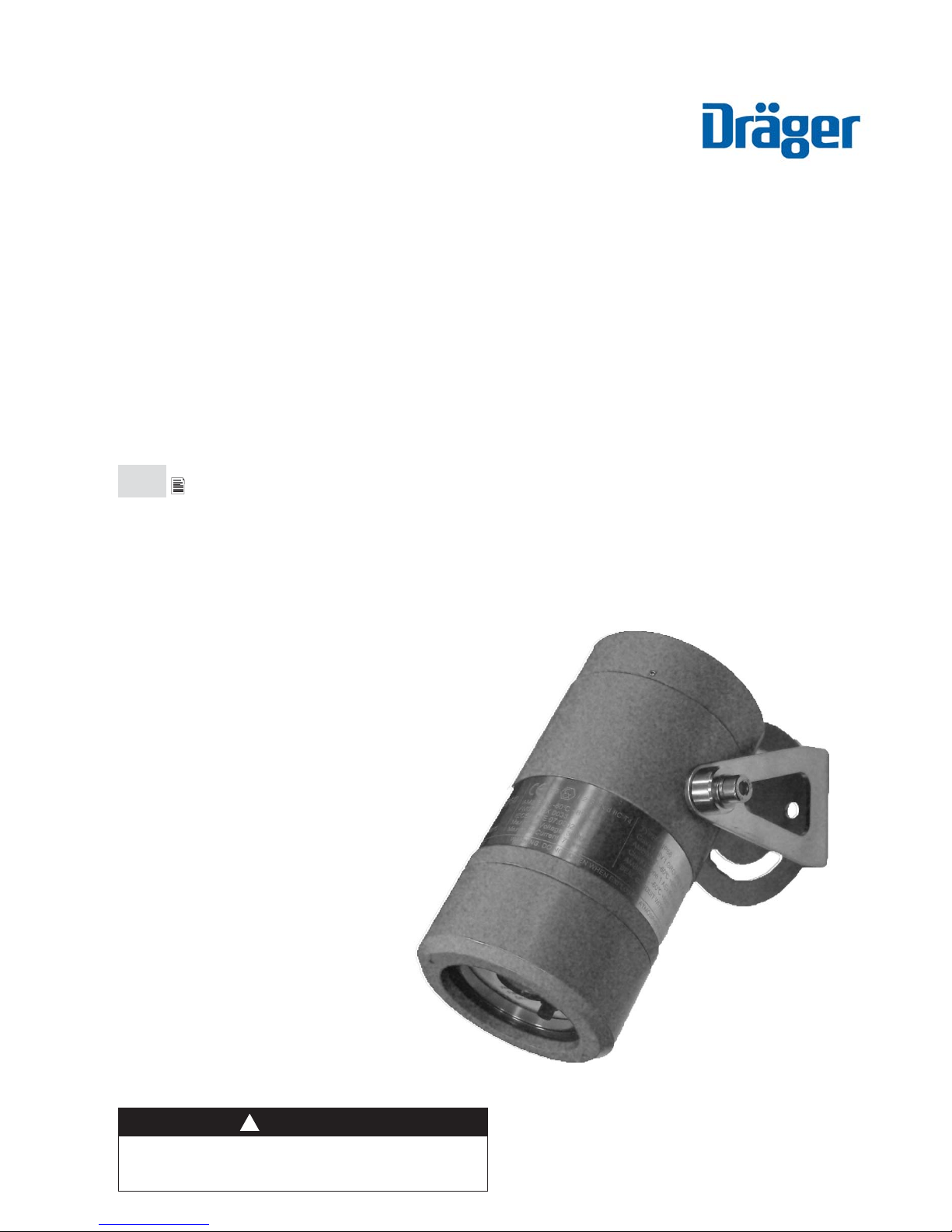
Dräger Flame 5000
Colour CCTV Flame Detector
Technical Manual
en
Technical Manual
2 - 34
WARNING
You must read, understand, and follow these instructions for use
before you use the flame detector in order to ensure the proper
operation and function of the flame detector.
!
Page 2

Contents
For Your Safety .................................................................................................................... 3
Intended Use .......................................................................................................................6
Operation .......................................................................................................................... 20
Maintenance ......................................................................................................................21
Fault Finding ..................................................................................................................... 23
Technical Specifi cations ................................................................................................... 24
Approvals ........................................................................................................................... 26
Accessories ....................................................................................................................... 27
Supplier’s Declaration of Conformity ............................................................................... 28
Approval Certifi cates ......................................................................................................... 29
Page 3

For Your Safety
3
For Your Safety
Strictly follow the Instructions for Use
Any use of the device requires full understanding and strict observation of these instructions. The device is only to be
used for the purposes specifi ed herein. This manual should be carefully read by any individuals who have or will have
responsibility for using or maintaining this product.
Maintenance
The Dräger Flame Detector 5000 must be inspected and serviced at regular intervals and a record kept. Repair and
general over-haul of the device may only be carried out by trained service personnel. We recommend that a service
contract be obtained with Dräger Safety UK Ltd and that all repairs also be carried out by them.
Under no circumstances should the detector housing be opened in a hazardous area. Detectors contain no user-
serviceable parts and should never be opened, other than for access to the terminal compartment. Under no
circumstances should any components be substituted. Failure to comply with this requirement may invalidate the
hazardous area certifi cation or disturb the critical parameters of the Dräger Flame Detector 5000 resulting in damage
to the device or failure to detect fi res. Observe the chapter ‘Maintenance’.
Use in areas subject to explosion hazards
The Dräger Flame Detector 5000 is certifi ed for and intended for use in potentially hazardous areas. Equipment and
components which are used in explosion-hazard areas and which have been inspected and approved in accordance
with international or European explosion-protection regulations may be used only under the specifi ed conditions. The
equipment or components may not be modifi ed in any manner. Do not drill holes in any housing, as this will invalidate
the explosion protection.
Check that the materials used in the construction of this detector are compatible with the environment in which they
will operate, and that they will not be aff ected by any anticipated contaminants. The detector should not be used in an
oxygen enriched atmosphere.
The purpose of the Dräger Flame Detector 5000 is to detect a fl ame or fi re. It may be installed in areas that contain
potentially explosive atmospheres, thus it is vital for your safety and that of others that its functions are understood and
that every aspect of installation, commissioning and maintenance are carried out correctly.
This manual is intended to inform you of all aspects of the Dräger Flame Detector 5000. However, if you are in any
doubt about any part of these instructions, any function of the equipment, or any operating procedure, please contact
Dräger Safety or your local distributor.
Page 4

4
For Your Safety
Attention
Information on power consumption and operating voltage of the detector can be found in the specifi cations section of
this manual. This should be read and taken into consideration when specifying cable core sizes to be used. In addition,
local regulations should be considered before wiring the system and installation should be completed by appopriately
trained personnel.
During system tests or maintenance, it is important that any control equipment is inhibited to avoid unwanted actuation
or alarms.
Dräger Safety UK Ltd.
Page 5
For Your Safety
5
Safety Symbols used in this Manual
While reading this Manual, you will come across a number of warnings concerning some of the risks and dangers you
may face while using the device. These warnings contain “signal” words that will alert you to the degree of hazard you
may encounter. These words, and the hazard they describe, are as follows:
DANGER
Indicates an imminently hazardous situation which,
if not avoided, will result in death or serious injury.
!
WARNING
Indicates a potentially hazardous situation which, if
not avoided, could result in death or serious injury.
!
CAUTION
Indicates a potentially hazardous situation which, if
not avoided, could result in physical injury.
!
NOTICE
Indicates a potentially hazardous situation which, if
not avoided, could result in damage to the product.
!
Page 6

6
Intended Use
Intended Use
Dräger Flame Detector 5000
For use in an area which may contain potentially explosive atmostphere. Used to monitor and trigger the necessary
control actions upon the detection of fi re or fl ame in a given environment
Understanding t he System
Principle of Operation
The Dräger Flame Detector 5000 can operate ‘stand alone’ or can be integrated with an approved control system.
Detectors are typically located throughout the installation in order to achieve specifi c detection coverage and ensure
that site performance requirements are met. All detectors are capable of providing live colour video images and fi re
alarm/fault signalling to the control equipment. Each detector incorporates within a single unit an imaging device,
digital signal processing hardware, and fi rmware algorithms to process live video images and recognise fl ame
features. The detectors are capable of operating independently: external control equipment is not required for normal
functions. However, if an external controller is installed then certain additional features become available, such as
remote confi guration and fi rmware management. A remote operator can interrogate the detector and, during an alarm
situation, visually verify the hazard. Each detector can be individually confi gured to operate seperately as a Flame
detector only, or Video Surveillance camera, or as a combined unit.
Detector Overview
The detector unit is comprised of two primary components, the detector enclosure, and the detector assembly. The
detector assembly should not be disassembled or tampered with in any way. The detector is shipped pre-assembled
and comes complete with all parts required for installation, including the bracket but excluding the client mounting
support, glands and cabling.
Optical Test
The camera implements an optical check for faulty or contaminated optics. The check measures the contrast in images
captured from the video sensor. If the contrast falls below a certain level, the detector will signal an optical fault. Optical
testing in the Visual Flame Detector can also be verifi ed manually using the Dräger FS-5000. Another manual method
is simply to view the video from the detector, if the video-out is connected.
Detector Sensitivity
The Dräger Flame Detector 5000’s response to a fi re depends on the fuel source and how it is released, fi re size and
distance, orientation to the detector and local ambient conditions. The typical parameters can be made available by
contacting Dräger Safety UK Ltd.
Explosion-Protection Approval
The explosion-protection approvals are valid fo use of the device in gas/vapour-air mixture of combustible gases and
vapours under atmospheric conditions. The explosion-protection approvals are not valid for use in oxygen eriched
atmostpheres. In the case of unauthorised opening of the enclosure, the explosion-protection approval is void.
Page 7
Intended Use
7
WARNING
Do not open the enclosure in the presence of an explosive
atmostphere.
!
WARNING
All permits and proper site procedure and practises must be
followed and the equipment must be isolated from the power
supply before opening the enclosure in the field.
!
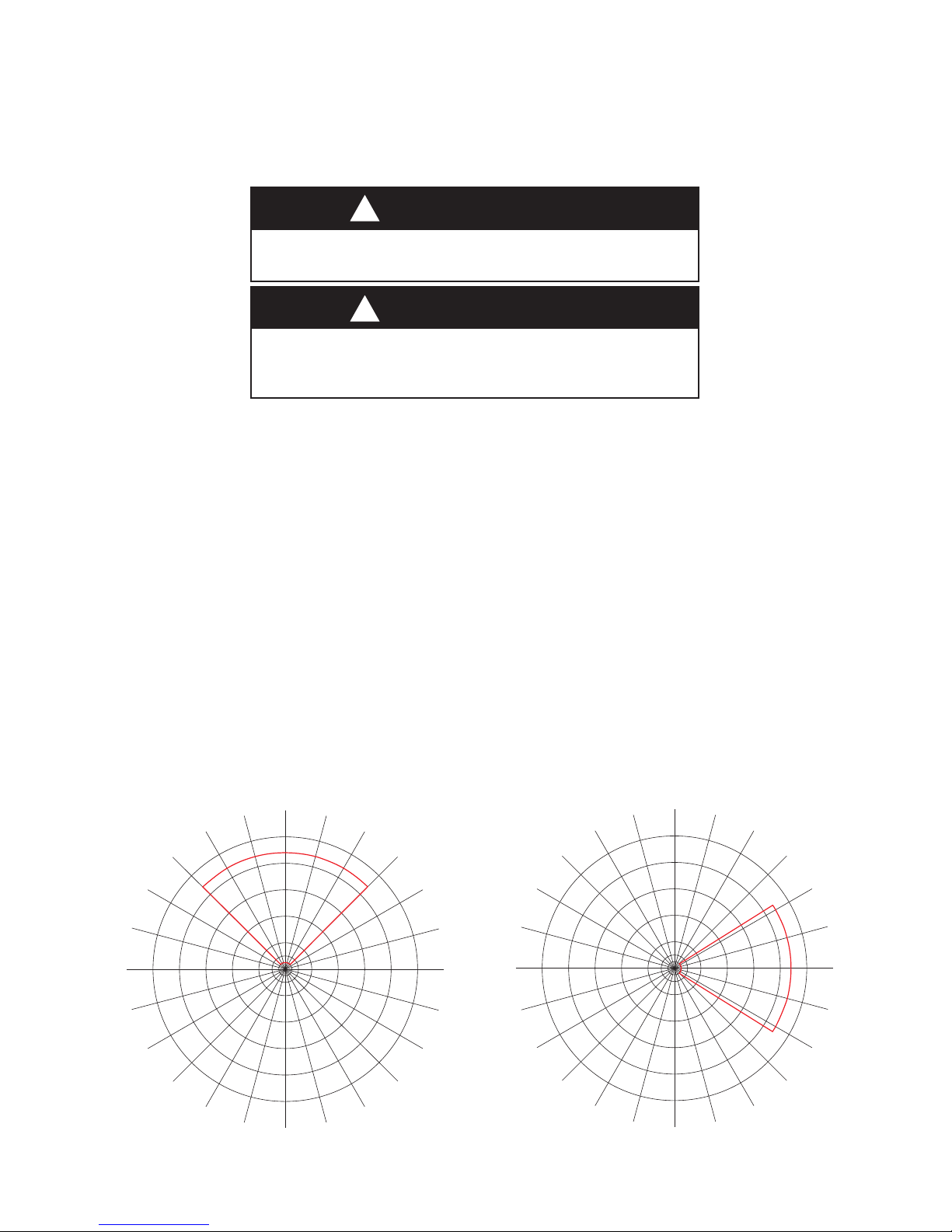
Field of View
The sensor can detect fi res of 0.1m2 or greater, at 44m within a 90° horizontal fi eld of view. The detector will only
respond to visible fl ames within the fi eld of view. Hence the detector will not to certain common sources of false alarms
such as refl ected fl are radiation. This also reduces the likelihood of cross-propagation of alarms caused by fi res or
combustion products of fi res burning out with the fi eld of view.
The detectors should be aligned to view the intended hazard taking into account any obstruction and congestion.
Software analysis of the actual detector coverage may be required to ensure adequate coverage of the hazards. This
analysis can also be used to optimise the number of detectors and the loop confi guration.
Visual Flame Detector does not have a traditional cone of vision like other IR fl ame detector’s. The detector’s fi eld of
view is a rectangular pyramidal shape and represents a radial projection of the detector’s rectangular sensing element.
The illustrations below show the Field of View and range for a fi re of 0.1m2.
5
0
m
3
0
m
4
0
m
2
0
m
1
0
m
5
m
0˚
15˚
30˚
45˚
-15˚
-30˚
-45˚
60˚
-60˚
-75˚
-90˚
-105˚
-120˚
-135˚
-150˚
-165˚
180˚
165˚
150˚
135˚
120˚
105˚
90˚
75˚
5
0
m
3
0
m
4
0
m
2
0
m
1
0
m
5
m
0˚
15˚
30˚
45˚
-15˚
-30˚
-45˚
60˚
-60˚
-75˚
-90˚
-105˚
-120˚
-135˚
-150˚
-165˚
180˚
165˚
150˚
135˚
120˚
105˚
90˚
75˚
Horizontal Field of View Vertical Field of View
Page 8

8
Installation of the Dräger Flame Detector 5000
Installation of the Dräger Flame Detector 5000
In considering the application of the Dräger Flame Detector 5000 it is important to know of any conditions that may
prevent the detector from responding. The detector provides reliable response to visible fl ames within its fi eld of view,
and insensitivity to common false alarm sources.
Solid obstructions or a direct view of intense light sources may interfere with the detector sensitivity. Scaff olding or
tarpaulins in the detector’s fi eld of view may reduce coverage. Contamination of the detector window may result in a
reduction in sensitivity.
The detector provides a live colour video image for surveillance of the protected area. As with conventional video
cameras the detector should not face directly towards the sun or a brightly lit scene. In such conditions the detector’s
automatic exposure control would darken the image in order to avoid overexposure; the resulting picture may be too
dark for surveillance purposes. To obtain the best possible picture the detector should be facing away from the sun.
In the case of an off shore vessel or platform, the detector should ideally be placed facing inwards towards the plant
and with minimal view of the horizon.
The detector has a horizontal fi eld of view of 90° and a vertical fi eld of view of 65°. The location and orientation of the
detector in relation to the protected area determines the actual footprint. Achieving the desired coverage depends on
congestion within the protected space, the location of the detector(s) and the distance of the detector from the hazard.
It may be necessary to install more than one detector within an area in order to achieve adequate coverage.
The detector sensitivity, expressed as fi re size at a distance, is determined visually by the apparent size of the fi re. This
is a function of the fuel source, how it is released and distance from the detector to the fi re. The detector response
time is relatively independent of fuel type and/or distance.
In common with other forms of fl ame detection, the detector’s sensitivity is reduced and potentially blinded by dense
obscurants such as smoke, fog and other airborne particulates. The detector is insensitive to arc welding, however
should not be conducted within 1m of the detector.
Mechanical Install.
Detector Enclosure
The Draeger Flame Detector 5000’s electronics are housed in an enclosure certifi ed for use in a hazardous areas. The
enclosure comprises of:
Front enclosure cover (including the faceplate window)•
Rear enclosure cover.•
Enclosure body (with certifi cation label). •
Mounting bracket. •
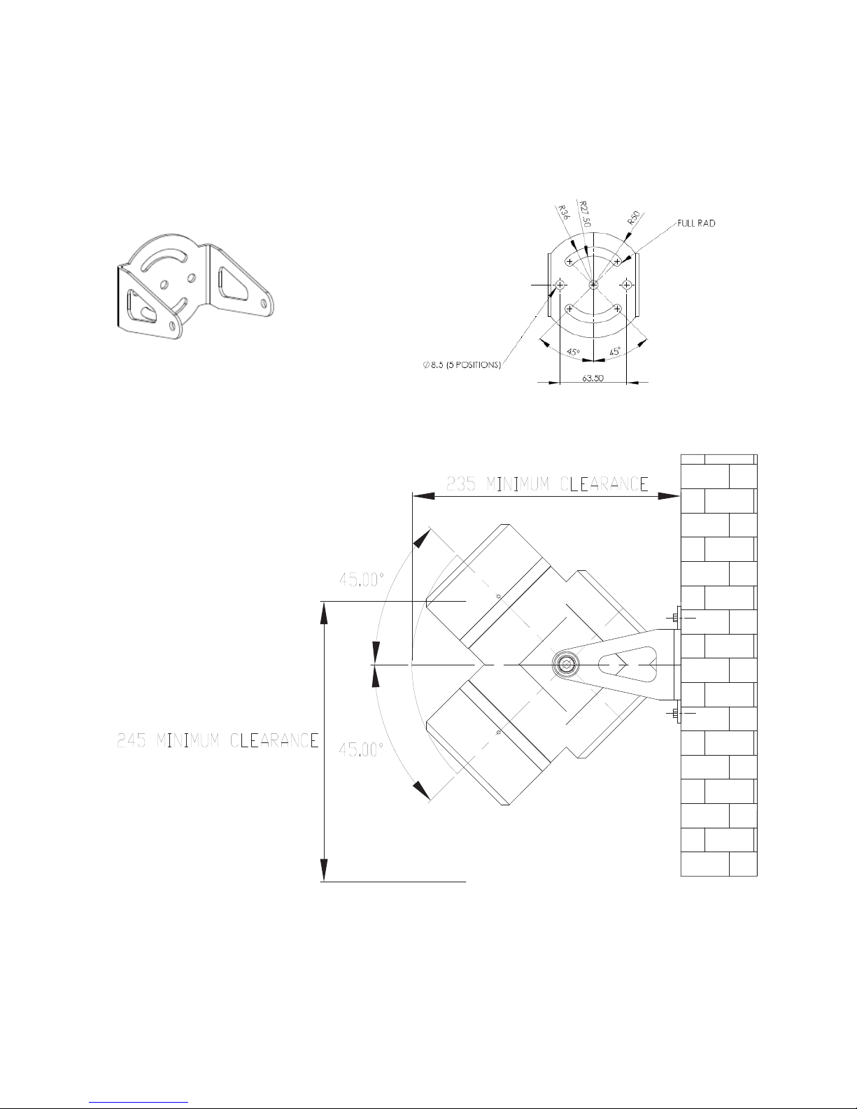
The mounting bracket allows the detector’s vertical orientation to be adjusted from 0-45°, and allows a horizontal
rotation of ±45 °.
Page 9
Installation of the Dräger Flame Detector 5000
9
Detector Enclosure with Bracket
Sighting requirements
Observe the following:
Ensure the mounting position is free from vibration or movement•
Prevent accidental knocking or forcing out of alignment •
Where snow or ice build-up is likely, the heater should be enabled•
To ensure the best possible video image the detector should be facing away from the sun•
Isolate as far as possible from local electrical interference sources•
Ensure suffi cient detection to achieve adequate coverage for all likely hazards•
Minimise exposure to contamination of the detector face plate•
Ensure ease of maintenance access to detector (i.e. direct, ladder or scaff old access)•
All these issues are of crucial importance to a successful installation, and they should be given great attention during
the detailed design, construction, and commissioning phases of the work.
WARNING
Do not drill any holes in the housing as t his will invalidate t he
explosion protection.
!
WARNING
Do not open the enclosure in the presence of an
explosive atmosphere.
!
Page 10

10
Installation of the Dräger Flame Detector 5000
Exposure to Flare Radiation
Flame detectors are frequently used where hydrocarbon fi re hazards are expected; these are quite often processing
plants where a fl are stack is in use nearby. The detector should not have a direct view of the fl are.
Flexibility of mounting location
The detector requires a clear unobstructed view of the potential hazard. In order to avoid local obstructions, such
as pipe-work and cable trays, a 2m helix should be provided in the detector cable to allow local repositioning of the
detector.
Mounting Arrangements
Firm, vibration free mountings are essential for the operation of optical systems and the detector should, wherever
possible, be fi xed to rigid mountings.
Thermal Disruption
Thermal convection plumes and exhaust gas plumes generally exhibit a visual ‘mirage’ eff ect. In most cases this does
not aff ect detector operation or sensitivity. The detector does not respond to black body radiation near the exhaust.
Optical Contamination
There are many sources of contamination such as oil, water (deluge water, rain and sea-spray), snow, ice, and internal
misting. The design of the detector incorporates an internal heater in order to resist condensation and ice build-up.
Excessive contamination of the detector faceplate may result in an increased maintenance requirement and potentially
reduce the detector’s sensitivity.
Where detectors are mounted at low level, care should be taken to avoid contamination (such as water and oil) from
equipment above the detector. Care should be taken in sighting the detector to minimise the likelihood of such
contamination.
Fog, smoke and other similar airborne contaminants aff ect the detector’s sensitivity by reducing the detector’s range.
Enclosed Areas
In enclosed areas, if dense smoke is expected to accumulate at the onset of the fi re, the detectors should be mounted
1-2m below the ceiling level.
The mounting bracket
The detector mounting bracket is designed to allow the detector to be mounted from a horizontal plane. The bracket
supplied with the detector and the dimensions of the fi xing holes are illustrated on the following page.
Page 11
Installation of the Dräger Flame Detector 5000
11
Detector mounting bracket Detector mounting bracket dimensions
Dimensions shown in Millimeters
Page 12

12
Installation of the Dräger Flame Detector 5000
Electrical Install
Detector Electronics Subassembly
The fi eld wiring is accessed by removing the rear enclosure cover and all terminations are accessible without the need
to access the electronics module mounted in the front portion of the enclosure.
WARNING
For European (ATEX) installations, IEC/EN60079-14 ‘Electrical
Installations in Hazardous Areas’ and ICE/EN60079-17
‘Inspection and Maintenance in Hazardous Areas’ should be
strictly observed.
!
WARNING
For installations all Local and International regulations should
be strictly observed.
!
Earthing & Screening Requirements
It is important to ensure that the system is correctly connected to earth. Incorrect or poor earthing can adversely aff ect
system operation and may result in intermittent RS485 communications and poor video image quality.
WARNING
The equipment must be properly earthed to protect against
electrical shock and to minimise electrical interference.
!
The system 0V should be connected to a clean earth at only one point; generally this should be at the panel power
supply (or 0V bus bar). Where PC equipment is connected to the RS485 and Video signals, care should be taken
to ensure that the PC’s and Panel’s power supply are at the same ground potential. Even small diff erences in earth
potentials can cause an earth fault current to fl ow resulting in video corruption. Where this is not possible either the
PC’s local supply should be isolated and the PC’s connected to the ‘system clean earth’, or alternatively, the Video and
RS485 signals should be isolated. The Dräger Safety UK Ltd twisted pair to BNC video converter (VTP4) and RS232
to RS485 converter (RS2485IF) can be used so long as the maximum potential diff erence between each earth does
not exceed ±5V, as identifi ed below.
In distributed systems with multiple DC-DC power supply units all 0V supplies must be connected together to a
common clean earth. Where this is not possible each system can either be connected to a local clean earth so long as
the maximum potential diff erence between each earth does not exceed +4 to -1Vdc, alternatively the Video and RS485
signals can be galvanically isolated from the central system. Where earth fault monitoring is used care should be taken
to ensure that the system 0V to earth potential is not exceeded.
The detector enclosure is to be connected to a local earth and the detector cable screens (shields) should be cut back
to the crotch and not terminated within the detector. If the detector enclosure cannot be connected to a local earth
Page 13

Installation of the Dräger Flame Detector 5000
13
then care should be taken to ensure the cable armour braid provides a suitable earth or that the enclosure earth stud
(external) is separately connected to a suitable earth point using a single core 4mm2 earth cable.
All detector cable screens should be connected to the local clean earth at the control panel. The screens (and twisted
pairs) should be maintained to within 1” (25.4mm) of the terminations at the detector, within all junction boxes and at
the control panel. Where unscreened cables are used for panel wiring, then all cables must be suitably twisted into
pairs and video cables should be segregated from other signal sources.
Power Supply
The detector requires an absolute minimum supply voltage of 18V, as measured at the detector terminals. The system
power supply voltage and power distribution should be arranged such that on the longest cable run the detector(s)
has a supply voltage of greater than 18V. All detectors must share a common 0V supply. In distributed systems with
multiple DC-DC power supply units all 0V supplies must be connected together. Where this is not possible the RS485
and Video signals may need to be galvanically isolated, such as with a fi bre optic transceiver.
To prevent RS485 communications or video corruption the maximum voltage drop on the 0V return must not exceed
+4V or -1V. Voltages greater than these will exceed the common mode input range of the RS485 and Video drivers.
Power supply cable selection is described in section: Detector Power Supply Cabling
Detector Wiring Terminals
The wiring terminals and confi guration links are mounted in the rear section of the enclosure and are accessible by
removal of the rear cover from the enclosure. The electronics and the fi eld terminals are separated so that there is no
reason to remove the electronics in order to access the fi eld terminals. This is to prevent damage to the electronics
when the unit is being connected to the fi eld cable.
The device is supplied in one of two options:
As a unit that provides relay contacts for the alarm and fault circuits across which alarm and end of line resistors 1.
are fi tted. When the unit is disconnected from the fi re panel, the output from terminals A and B switch to the
RS485 protocol; this allows a Dräger Engineer access to the detectors confi guration from the local equipment
room.
As a unit that provides 4-20mA output. When the unit is disconnected from the fi re panel, the output from terminals 2.
A and B switch to the RS485 protocol; again this allows a Dräger Engineer access to the detectors confi guration
from the local equipment room.
This may then be used to access the software revision within the detector via the ‘get settings’ menu as described in
the ‘RS485 Communications’ section.
The alarm relay and the 4-20mA output is factory selectable for latching and non-latching operation. If the latching
mode is selected then if an alarm is generated the detector will remain in alarm until the power supply to the unit
is interrupted. If the non-latching operation is selected then the detector will remain in alarm for a minimum of 15
seconds, the fi re panel to which the detector is connected must be capable of latching the alarm and there is no need
to interrupt the power supply to the detector to reset the alarm. Local authority having jurisdiction approval is required
for connection to FM Approved fi re alarm control units.
Page 14

14
Installation of the Dräger Flame Detector 5000
Detector Wiring Terminals (Rear Detector with cover removed)
1
8
7
14
Relay Mode Connections
The following table provides a function summary of each terminal if the detector is ordered in relay mode.
Terminal Terminal No. Description
+24v 1 +24V Supply A
0v 2 0V Supply A
A 3 Sense from fi re panel
B 4 Return signal to fi re panel
VID+ 5 Video +Ve
VID- 6 Video –Ve
485A 7 RS485 termination +Ve
+24v 8 +24V Supply B
0v 9 0V Supply B
C 10 EOL resistor
D 11 EOL resistor
ALRM 12 Alarm Resistor
ALRM 13 Alarm Resistor
485B 14 RS485 termination -Ve
If the detector is connected in the above manner and if a fi re alarm is signalled, with the alarm resistor connected
between terminals 12 & 13, then the alarm resistor will appear across terminals 3 & 4. The EOL resistor connected
between terminals 10 & 11 normally appears across terminals 3 & 4 and in the event of a fault the resistor appears open
circuit. If terminals 3 & 4 are disconnected from the fi re panel, these wires then provide a RS485 connection to the
detector. This connection may then be used to up load or down load information to the detector.
1
8
7
14
0 VDC
+24 VDC
To F ir e Pane l
VIDEO +VE
VIDEO -VE
1
2
3
4
5
6
From Fire Panel
Page 15

Installation of the Dräger Flame Detector 5000
15
4–20mA Connections
The following table provides a function summary of each terminal if the detector is ordered in 4-20mA mode.
Terminal Terminal No. Description
+24v 1 +24V Supply A
0v 2 0V Supply A
A 3 Tie to +24 Volts at panel
B 4 4-20 mA source
VID+ 5 Video +Ve
VID- 6 Video –Ve
485A 7 RS485 termination +Ve
+24v 8 +24V Supply B optional
0v 9 0V Supply B optional
C 10 Not used
D 11 Do not connect
ALRM 12 Do not connect
ALRM 13 Not used
485B 14 RS485 termination -Ve
If the detector is connected in the above manner if a fi re alarm is signalled then the 4-20mA outputs generate 18mA
if a fault develops the 4-20mA signal indicates 0 or 2 mA dependant on the fault see table for default current levels. If
terminals 3 & 4 are disconnected from their connections these wires then provide a RS485 connection to the detector.
This connection may then be used to up load or down load information to the detector.
Default 4-20mA settings
Event Output
Catastrophic Failure 0mA
Optical Fault 2mA
Healthy condition 4mA
Alarm 18mA
Over range 21mA
There is a tolerance on the mA outputs of ±5%, other values maybe selected at the point of order.
1
8
7
14
0 VDC
+24 VDC
4-20mA Source
VIDEO +VE
VIDEO -VE
1
2
4
5
6
Page 16

16
Installation of the Dräger Flame Detector 5000
RS485 Communications
The optional RS485 twisted pair cable is connected to the detector
RS485A +ve signal terminal and the RS485B -ve signal terminal. The
RS485 connection can be used to read the software revision within the
detector. In order to access this information connect the RS485 input of a
RS485 to RS232 to terminals 7 & 14. Connect the RS232 input of a RS485
to RS232 to a PC install DFG software on the PC. The DFG Software can
be used to interogate the Flame 5000 Detector, for any further assistance
contact Dräger Safety UK Ltd.
The software revision will be shown in the get settings box as indicated
adjacent.
Video (twisted pair)
The video twisted pair cable is connected to the detector +Video signal on
terminal 5 and the -Video signal on terminal 6.
Point to Point Connections
In a point to point connection a single detector is connected to the power, RS485 (or mA or Relays) and Video cables.
This arrangement has the best reliability and availability since any single failure in the fi eld equipment or cabling aff ects
only the one detector.
Cable Selection
The installation, local regulations, and standards determine the overall cable specifi cation. This section specifi es
suitable cable characteristics to ensure correct operation of the fl ame detector. There are several diff erent cabling
methods available, each with advantages and disadvantages:
Three twisted pair cable, one each for DC power, RS485 and video signals•
Two twisted pair cable for DC power and mA or Alarm relays, interchangeable with RS485•
Three twisted pair cable for DC power and mA, or Alarm relays, interchangeable with RS485 and one pair for •
video.
Three wire, DC power and mA (Current source output).•
NOTE: Table below shows absolute maximums for cable lengths; try not to approach these values.
Typical cable lengths (24V Supply)
Installation based on 24V
nominal supply
Number of Flame
Detectors
Maximum
Power (W)
Maximum Cable Length (m) with
1.5mm2 Conductors (12 ohms/km)
Maximum Cable Length (m) with
2.5mm2 Conductors (7.6 ohms/km)
Detector and Heater 1 18 333 506
Detector (no Heater) 1 6 1,000 1,578
NOTE: Increasing the supply voltage to 26V would increase the maximum cable lengths by +30%.
The overall performance and the transmission distance depends on the selected twisted pair cable. Individually
screened twisted pairs off er better electrical immunity.
Page 17

Installation of the Dräger Flame Detector 5000
17
It is not necessary for the DC power cable to be a twisted pair or individually screened, a 2-core stranded cable with
an overall screen is suffi cient. The minimum conductor size is determined by the cable length, the number of Flame
Detectors on each loop, and the maximum allowed voltage drop at the last detector.
To prevent RS485 and Video common mode problems this is limited to a maximum of four volts (4V) on the negative
supply (0V).
Equation 1 : DC Supply Conductor Resistance Calculation
2
VdVs
)V4(V
minmin
pd
d
¸
¸
¸
¸
¹
·
¨
¨
¨
¨
©
§
¸
¹
·
¨
©
§
u
y
km
min
pd
km
L
Vs
NPd
V
R
Vpd = Potential across each conductor (limited to 4V)
Vsmin = Minimum Supply Voltage
Vdmin = Minimum Detector Voltage (18V)
Pd = 18 watts per Flame Detector (inc. Heater) or 6
watts excluding Heater
N =Number of Detectors
Lkm = Cable Length in Kilometres
Rkm = Maximum Conductor Resistance per Kilometre
Use the value of Rkm calculated above to select a suitable gauge of conductor, alternatively, to calculate the maximum
cable length from a known conductor resistance swap Rkm and Lkm in the above equation. The supply voltage and cable
cross-sectional area (which equates to its resistance) limits the maximum cable length, increasing the supply voltage
(up-to a maximum of 32V) can dramatically increase cable length.
Prudence dictates that a cable is selected with a lower resistance than calculated above, with suffi cient allowance
for the eff ects of crimps, terminals and ageing which can increase overall resistance. Where a single cable cross
sectional area cannot be found to satisfy both the needs of the power and signal conductors consideration should be
given to using multiple paralleled conductors of a smaller cross section for the power.
Video (Twisted Pair)
The video cabling should be a twisted pair stranded cable with an overall screen. Where multi-core cables are used
then individual screened twisted pairs are recommended. The cable should have the following characteristics:
Video (Twisted Pair) Cable Characteristics
Cable
Characteristic
Characteristic
Impedance
Capacitance Conductor
Resistance
Attenuation @
1MHz
Inductance
Nominal 150Ω 50nf/Km - - - - - -
Absolute Limit 90Ω to 150Ω 100nf/Km 150R 6db 0.7mH/Km
The maximum cable length is dependent on the cable manufacturer’s attenuation specifi cation, which is approximately
proportional to conductor size.
The characteristic impedance of a transmission line is a function of the physical dimensions of the conductor and the
permittivity of the dielectric (the insulation), at high frequencies this is approximately equivalent to:
Page 18

18
Installation of the Dräger Flame Detector 5000
Equation 2: Characteristic Impedence Calculation
L = Cable Impedance (mH)
C = Cable Capacitance (F)
Zo = Characteristic Impedance (Ohms)
CL)(Zo y ȍ
The RS485 communications cabling should be a twisted pair stranded cable with an overall screen. Where multi-
core cables are used then individual screened twisted pairs are recommended. The cable should have the following
characteristics:
RS485 Communications Cable Characteristics
Cable
Characteristic
Characteristic
Impedance
Capacitance Conductor
Resistance
Attenuation @ 1MHz Inductance
Nominal 120Ω 50nf/Km - - - - - -
Absolute Limit 90Ω to 120Ω 100nf/Km 120Ω 12dB 0.7mH/Km
The maximum cable length is dependent on the cable manufacturer’s attenuation specifi cation, which is approximately
proportional to conductor size. The characteristic impedance of a transmission line is the same as for the video
above.
Installation Check-Points
Experience has shown that poor installation and commissioning practice may result in an unreliable fi re detection system
that is prone to malfunction, unwanted alarms, and at the same time fails to meet the site performance targets. Before
installing the detector it is important to take into account where it is to be located and how it is to be mounted.
Mechanical Installation
When locating the Dräger Flame Detector 5000 consideration should be given to maintenance access to the •
detector.
The detector mounting should be secure and vibration free.•
It is advisable to check the detection locations, prior to fabrication of the mounting supports, as changes are •
frequently made during construction at site which can aff ect detector coverage.
The installation should allow for easy detector removal for maintenance or repair.•
The detector should be fi xed to a stable supporting structure using the mounting bracket provided. The supporting 1.
structure must allow for horizontal adjustment of the detector orientation. The support structure should be in place
prior to detector installation.
The threaded fl ame path of the enclosure cover and body must be protected from damage during installation. Any 2.
such damage can destroy the validity of the enclosure.
The detector electronics shall be protected from mechanical damage and external sources of EMI such as X-rays, 3.
RFI and electrostatic discharge.
Fit the mounting bracket to the support structure using 8mm bolts (not provided). The detector (bracket) should 4.
be oriented to provide the desired coverage.
The hex head bolts should be fi tted to the enclosure body prior to mounting to the bracket. The detector enclosure 5.
Page 19

Installation of the Dräger Flame Detector 5000
19
body should then be fi tted to the mounting bracket. The bolts fi t into key slots in the bracket. Twist the enclosure
to locate the bolts; these are then tightened using a 6mm Allen key.
Electrical Installation
In order to maintain compliance with the EMC regulations it is essential the electrical installation be engineered
correctly.
It is advisable to check the detection locations, prior to fabrication of the mounting supports, as changes are •
frequently made during construction at site.
Detector cabling must be segregated from cables carrying high-speed data or high energy and/or high frequency •
signals and other forms electrical interference.
The detector requires a clear unobstructed view of the local hazard. In order to avoid local obstructions, such as •
pipe-work and cable trays, a 2m helix should be allowed in the detector cabling.
The detector should only be installed just prior to commissioning. Experience shows that the detector can be •
damaged due to cable testing operations (Insulation Tests, etc)
Isolate all associated power supplies. Ensure that they remain OFF until required for commissioning.1.
The threaded fl ame path of the enclosure cover and body must be protected from damage during installation. Any 2.
such damage can destroy the validity of the enclosure.
The electronics subassembly shall be protected from mechanical damage and external sources of EMI such as 3.
X-rays, RFI and electrostatic discharge.
The enclosure’s external earth stud should be connected to a local earth point.4.
Remove the blanking plug(s) from the enclosure body gland entries.5.
Fit approved cable glands using sealing washers to maintain ingress protection.6.
Prepare the cable tails. The cable screens should be cut back to the crotch at the detector and insulated from 7.
contact with the enclosure or any other local earth. The twist in each pairs should be maintained to within 1”
(25mm) of the termination. Cable tails should be 8” (200mm) long.
Where plastic junction boxes are used the cable screens (shields) should be maintained to within 1” (25mm) of 8.
the termination and fully insulated.
Where unscreened cables are used for panel wiring, then all cables must be suitably twisted into pairs and video 9.
cables should be segregated from other signal sources.
All cable screens (shields) should be connected to the local clean earth at the control panel. The screens and 10.
twisted pairs should be maintained to within 1” (25mm) of the terminations.
Page 20

20
Operation
Operation
Detector Start-up procedure
When the power is initially turned on there is a delay of approximately thirty seconds. The system performs an internal
test and system initialisation.
Detector Signals
The Flame detector generates a 0-20mA signal to indicate its status, or provides relay outputs. This should be checked
during the installation of the detector. Alternatively the status and operation of the device can be monitored by the
colour of the LED illuminated.
WARNING
Operators must be properly trained and aware of what actions
to take in the event of a fire being detected.
!
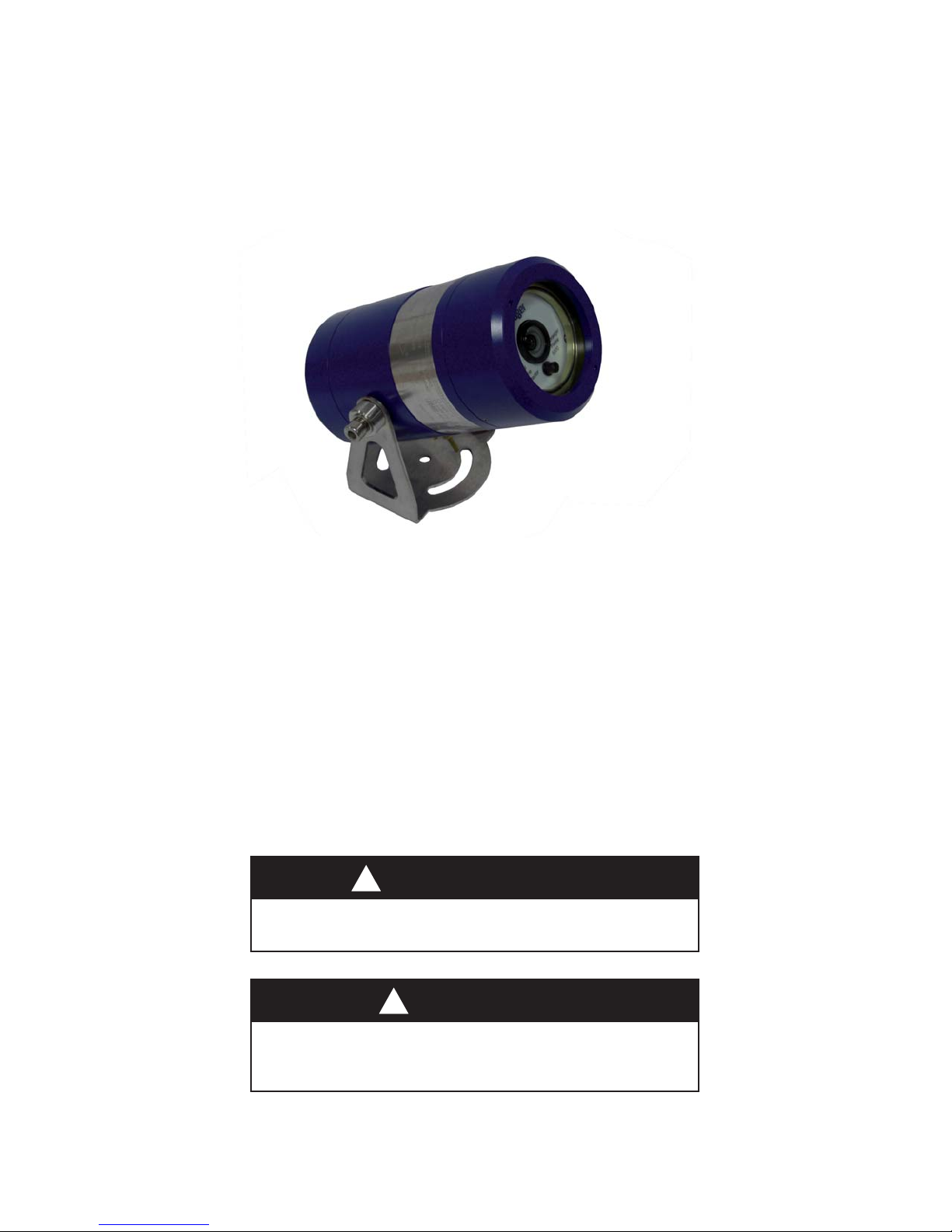
Status Indicators
The detector LED indicator is used to reveal the Dräger Flame Detector 5000’s current state, as shown below:
LED Status Diagnostic Chart
LED Colour Status Indicator
Steady OFF No Power
Green Healthy
Steady Yellow Fault
Flashing Yellow/Green 24V/0V terminals polarity
reversed.
Red Alarm
Current (Source) isolated signal output
Event Output
Catastrophic Failure 0mA
Optical Fault 2mA
Healthy condition 4mA
Alarm 18mA
Over range 21mA
The LED Status indicator is located on the face of the detector underneath the camera lens, as illustrated in the graphic
below.
Draeger
Flame
5000
Detector
Flame
Visual
Draeger
Flame
5000
Detector
Flame
Visual
Page 21

Maintenance
21
Maintenance
Detector Maintenance
WARNING
Repair of all equipment should be only performed in a safe area
and by trained personnel.
!
Once installed there are no user serviceable parts within the detector. The only servicing requirements are to ensure
that the detector is fully functional and to ensure that the lenses are clean.
The terminal compartment cover and front cover threads must be lightly lubricated with non-setting grease prior to
re-assembly.
This maintenance schedule is intended for guidance only. The actual level of maintenance required will depend on
the severity of the operating environment and the likelihood of damage or the rate of contamination from oil, sea spray,
deluge system etc. It is advisable to regularly review maintenance reports and adapt the maintenance period to the
operating environment. A function test of the detectors using the Dräger FS-5000 (See Accessories, page 26) should
be carried out regularly.
Maintenance Intervals
Periodic maintenance checks may be performed in accordance with appropriate codes of practice or local regulations
e.g. in Europe EN 60079-17 applies.
These fi rst fi ve points relate to the general inspection and maintenance of the detector and faceplate, this should be
carried out at least every 6 months.
Detectors that require maintenance should be taken off line and inhibited. Detectors which require to be opened •
up will need to be isolated electrically. Ensure that panel wiring and terminations associated with all units under
test are in good order.
Ensure that detector mounting arrangements are secure and undamaged.•
Ensure that the detector enclosure is intact and undamaged.•
Ensure that all associated cables and glands are correctly made up, secure and undamaged.•
Clean the enclosure faceplate (outside) with a mild detergent solution and a soft cloth until the window is clear •
of all contamination. Wash the window thoroughly with clean water and dry with a clean lint free cloth or tissue.
Assess requirement for opening the enclosure, for maintenance or cleaning.
The nine points below are for more specifi c inspection and maintenace of the detector enclosure, which should be
performed at least once a year. These points focus as a close external visual inspection and internal inspection if
required.
Open the detector enclosure, if required, by removing the enclosure cover. This exposes the enclosure fl ame path •
and detector electronics. Avoid damage to the fl ame path and faceplate.
Clean the enclosure cover and body fl ame paths with a dry clean cloth to remove any contamination. If the fl ame •
path or threads are badly pitted the component should be replaced.
Page 22

22
Fault Finding
Check the ‘O’ ring seal on the enclosure cover to ensure that it is not damaged or perished; replace as required. •
NOTE: That the ingress protection is compromised if the seal is not correct.
Clean the enclosure faceplate (inside) with a mild detergent solution and a soft cloth until the window is clear of •
all contamination. Wash the window thoroughly with clean water and dry with a clean lint free cloth or tissue.
No-setting waterproof grease should be evenly applied to the fl ame path on both the enclosure cover and body.•
Clean the detector lens. This should be done with a soft, dry and clean cloth. Avoid touching the electronics.•
Clean the detector enclosure faceplate. Use a degreasing agent on the outside in order to remove deposits.•
Visually inspect detector electronics and inside the enclosure body for any sign of damage or moisture, replace •
or rectify as required.
The enclosure cover must be screwed on to a minimum of 5 full turns or until fully tight and secured using the •
locking screw provided.
The remaining points cover detector function testing, this should be done on a continuous basis or every 6 months
depending on the environment.
Reinstate the detector back into service.•
Ensure that ‘inhibits’ are applied, then, using the Dräger FS-5000, function test the detector. Note the detector •
LED indicator, within the detector housing, changes colour to RED. Check the complete display system for
correct function and indication.
Functional Testing
The detector can be function tested using the Dräger FS-5000, which has been specifi cally designed to provide a
convenient means of fi eld testing the detector.
CAUTION
Use only Draeger approved parts and accessories wit h t his
equipment.
!
CAUTION
Do not attempt to replace the window as the glass and the
front cover are individually matched pairs to me the stringent
requirements of the hazardous area certification.
!
CAUTION
To maintain safety standards, commissioning and regular
maintenance should be performed by qualified personel.
!
Page 23

Fault Finding
23
Fault Finding
Removal of the Electronics
There are no user replaceable parts within the electronic module, any attempt to repair or dismantle the electronic sub-
assemblies will void the warranty. If any fault is suspected within the electronics module the module is to be returned
to Dräger Safety UK Ltd for investigation and repair if required.
Diagnostics
It is impossible to provide fault diagnostics for every possible detector fault. In all cases it is advised that the following
best practises are followed:
Only make one change at a time (changing more than one part at a time makes diagnosis very diffi cult)•
Check the most obvious possible causes fi rst•
Work systematically through the problem•
Keep good notes on the original problem, each step taken and the results observed•
Power Supply
If the detector LED indicator is OFF then there may be a power supply fault. When investigating power supply faults
it is important to check that all voltages are within the detectors operating range (18V - 32V) under full load conditions
as the voltages measured under no load conditions can be misleading.
Live Video Images
The live video signal is susceptible to more potential problems than the alarm signals. The signal is an analogue
transmission and available for operator scrutiny. The cabling is critical to video image quality. Due to the nature of the
video signal, video corruption can appear diff erently on each detector/installation.
Page 24

24
Technical Specifi cations
Technical Specifi cations
Mechanical
Enclosure
Enclosure Material: Aluminium Alloy Grade LM25, Stainless Steel 316
Enclosure Finish: Epoxy Coated Finish, Dräger Blue
Weight: 2.5 kg, 5.5 lbs (2.8 kg, 6.2 lbs Stainless Steel ver)
Dimensions (L x D): 220 x 100 mm, (9” x 4” inches)
Cable Entries: M20, M25 or 3/4” NPT
Terminal Wire Size: 2.5mm
2
Ingress Protection: IP 66, NEMA 4X
Temperature & Humidity
Operating T
amb
: -60°C to +85°C T4
Storage T
amb
: -60°C to +85°C
Humidity: 5-95% Relative Humidity Non-condensing
Mounting
Support Fixings: M8 x2
Vertical Adjustment: 0-45°
Axial (Horizontal) Adjustment: ±45°
Page 25

Approvals
25
Electrical
Operating Voltage: 18-32VDC (24VDC Nominal) inc ripple, (Max 30VDC in Canada)
Supply Ripple: 1V pk-pk
Power Consumption: 6W (max. 15W with Heater)
Heater Power Consumption: 12W
Detector Shutdown Voltage:
(low supply)
<17VDC
Power-On Delay: No more than 30 seconds, during in which System Testing and System
Initialisation occurs.
RS 485 Transceiver
Line Termination Resistor: 120 Ω
Driver Diff erential: 1.5 VDC
Driver Fan Out: 0-3 UL
Receiver Common Mode
Input Range:
-7 to +12 VDC
Receiver Input Threshold: -0.2 VDC (LO) to +0.2 VDC (HI)
Receiver Input Resistance: >12 kΩ
Receiver Unit Load: 1
Video Driver (Twisted Pair)
Line Termination Resistor: 150 Ω
Driver Output Resistance: 150 Ω
Driver Diff erential Output
Voltage:
4 VDC
Driver Diff erential Output
Voltage (loaded):
2 VDC
Driver Shutdown Resistance
(TR I-STATE):
4.8 kΩ
Driver Fan Out: 0-1 UL
Page 26

26
Approvals
Approvals
ATE X
Certifi cate Number: FM07ATEX 0033
II 2 G Exd IIC
IECEx
Certifi cate Number: FME 07.0002
FM
Class I Div 1 Groups B, C, D, T4
Ambient: -60°C to +85°C
Class I Zone 1 AEx/Ex d IIC T4
Ambient: -60°C to +85°C
CE
GEC: EN55022 & 082
Electromagnetic
Compatibility:
Emissions:
Immunity:
Conducted Emissions:
Radiated Emissions:
ESD:
RF Field (Amplitude):
Transient:
Surge:
RF Field (Common Mode):
EN61000-6-3:2001
EN50130-4:1995 +A1:1998 +A2:2003
EN55022:1998 Class/Level B
EN55022:1988 Class/Level B
EN61000-4-2:1995 ±6kV (Contact) ±8kV (Air)
EN61000-4-3:2002 +A1:2002 10V/m 100% & 80% modulation
EN61000-4-4:1995 +A1:2001 +A2:2002 ±1kV
EN61000-4-6:1995 +A1:2001 Line - Line , Line - Earth ±1kV
EN61000-4-6:1996 +A1:2001 10V rms 100% & 80% modulation
Response Time: min. 4 seconds (upto 30 seconds max.)
Operating Distance: 2-44 m
Hazardous Area Label
This label shows the certifi cation and conditions of the Dräger Flame Detector 5000.
TYPE: FLAME 5000
SERIAL No:
YEAR:
AMBIENT: -60ºC +85ºC
AMBIENT: -60ºC +85ºC
FM07ATEX 0033
IECEx FME 07.0002
Maximum Voltage: 30VDC
Maximum Current: 700mA
TYPE 4, IP66
Class I DIV 1 GROUPS B,C,D,T4
AMBIENT: -60ºC +85ºC
Class I Zone 1 AEx/Ex d IIC T4
AMBIENT: -60ºC +85ºC
SEAL CONDUIT WITHIN 18" OF ENCLOSURE ENTRANCE
1725 II 2 G Ex d IIC T4
3260
ENTRY:
½" NPT
¾" NPT
Single
Dual
M25
M20
WARNING: DO NOT OPEN WHEN EXPLOSIVE ATMOSPHERE MAY BE PRESENT WARNING: REFER TO FLAME 5000 TECHNICAL MANUAL BEFORE INSTALLING OR MAINTAINING THIS UNIT
Draeger Safety U.K. Limited, Blyth,
Northumberland, NE24 4RJ
, U.K.
Manufactured by: Micropack Engineering
Aberdeen, Scotland, AB12 4RR
Page 27

Accessories
27
Accessories
Description Part Number
Dräger FS-5000 420 93 07
Dräger CCTV Balanced Line to BNC Video Converter 420 93 27
Dräger Flame 5000, M20, 4-20mA, PAL video mode, Aluminium 420 93 08
Dräger Flame 5000, M20, Relay, NTSC video mode, Aluminium 420 93 09
Dräger Flame 5000, 3/4 NPT, Relay, NTSC video mode, Aluminium 420 93 10
Dräger Flame 5000, 3/4 NPT, 4-20mA, PAL video mode, Aluminium 420 93 11
Dräger Flame 5000, M25, 4-20mA, PAL video mode, Aluminium 420 93 33
Dräger Flame 5000, M25, Relay, NTSC video mode, Aluminium 420 93 34
Dräger Flame 5000, M20, 4-20mA, PAL video mode, Stainless Steel 420 93 20
Dräger Flame 5000, M20, Relay, NTSC video mode, Stainless Steel 420 93 21
Dräger Flame 5000, 3/4 NPT, Relay, NTSC video mode, Stainless Steel 420 93 22
Dräger Flame 5000, 3/4 NPT, 4-20mA, PAL video mode, Stainless Steel 420 93 23
Dräger Flame 5000, M25, 4-20mA, PAL video mode, Stainless Steel 420 93 35
Dräger Flame 5000, M25, Relay, NTSC video mode, Stainless Steel 420 93 36
Dräger Flame 5000, M20, 4-20mA, NTSC video mode, Aluminium 420 93 48
Dräger Flame 5000, M20, Relay, PAL video mode, Aluminium 420 93 49
Dräger Flame 5000, ¾ NPT, 4-20mA, NTSC video mode, Aluminium 420 93 50
Dräger Flame 5000, ¾ NPT, Relay, PAL video mode, Aluminium 420 93 51
Dräger Flame 5000, M25, 4-20mA, NTSC video mode, Aluminium 420 93 52
Dräger Flame 5000, M25, Relay, PAL video mode, Aluminium 420 93 53
Dräger Flame 5000, M20, 4-20mA, NTSC video mode, Stainless Steel 420 93 54
Dräger Flame 5000, M20, Relay, PAL video mode, Stainless Steel 420 93 55
Dräger Flame 5000, ¾ NPT, 4-20mA, NTSC video mode, Stainless Steel 420 93 56
Dräger Flame 5000, ¾ NPT, Relay, PAL video mode, Stainless Steel 420 93 57
Dräger Flame 5000, M25, 4-20mA, NTSC video mode, Stainless Steel 420 93 58
Dräger Flame 5000, M20, Relay, PAL video mode, Stainless Steel 420 93 59
Page 28

Supplier’s Declaration of Conformity
Page 29

Approval Certifi cates
Page 30

Page 31

Page 32

Page 33

Page 34

Page 35

Draeger Safety UK Ltd
Ullswater Close
Blyth Riverside Business Park
Blyth, Northumberland
NE24 4RG, United Kingdom
Tel: +44 (0)1670 352 891
Fax: +44 (0)1670 540 033
www.draeger.com
4209319_01_2008_en
© Draeger Safety UK Ltd
3rd Edition - February 2008
Subject to alteration
Distributed in the US by:
Draeger Safety, Inc
101 Technology Drive
Pittsburgh, PA 15275
USA
Tel: +1 412 787 83 83
Fax: +1 412 787 22 07
Telex: 0230866704
 Loading...