

Page 1
Dräger X-dock 5300
Dräger X-dock 6300/6600
Gebrauchsanweisung
de
4
Instructions for Use
en
16
Notice d’utilisation
fr
27
Instrucciones de uso
es
39
Instruções de uso
pt
51
Istruzioni per l'uso
it
63
Gebruiksaanwijzing
nl
75
Brugsanvisning
da
87
Käyttöohjeet
fi
98
Bruksanvisning
no
109
Bruksanvisning
sv
120
Instrukcja obsługi
pl
131
Руководство по зксплуатации
ru
143
Upute za uporabu
hr
156
Navodilo za uporabo
sl
167
Návod na použitie
sk
179
Návod k použití
cs
191
Инструкция за употреба
bg
203
Instrucţuni de utilizare
ro
215
Használati útmutató
hu
227
Οδηγίες Χρήσης
el
239
Kullanma talimatları
tr
251
使用说明
zh
262
Page 2

Page 3
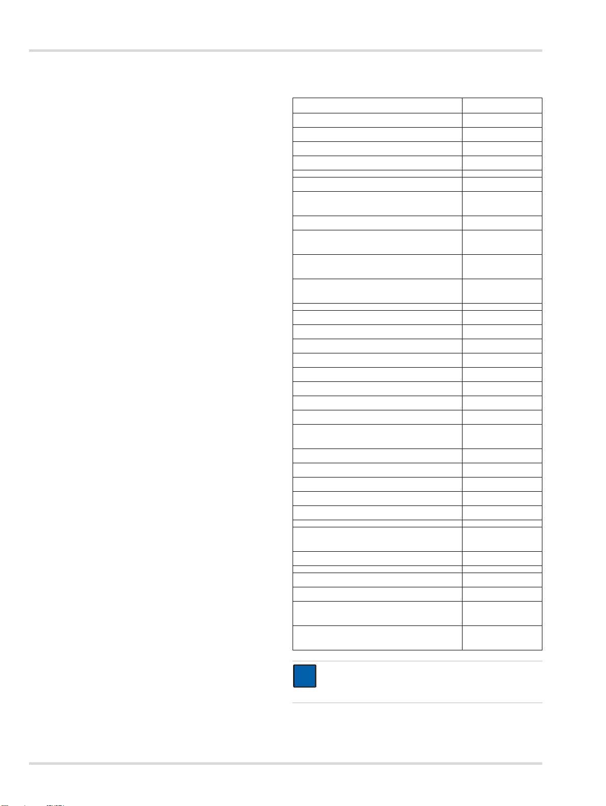
0
X-dock 5300 (X-am)
X-dock 6300/6600
X-dock 5300 (Pac) X-dock 6300/6600
X-dock 5300/6300 X-dock 6600
max. 10
00133286.eps
1 2
3
4
5
8
6
7
13
16
17
1918
15
14
12
11
9
10
13
Page 4
Zu Ihrer Sicherheit
!
!
i
i
1 Zu Ihrer Sicherheit
1.1 Allgemeine Sicherheitshinweise
Vor Gebrauch des Produkts die Gebrauchsanweisung auf-
merksam lesen.
Gebrauchsanweisung genau beachten. Der Anwender
muss die Anweisungen vollständig verstehen und den Anweisungen genau Folge leisten. Das Produkt darf nur entsprechend dem Verwendungszweck verwendet werden.
Gebrauchsanweisung nicht entsorgen. Aufbewahrung und
ordnungsgemäße Verwendung durch die Nutzer sicherstellen.
Nur entsprechend geschultes und fachkundiges Personal
darf dieses Produkt verwenden.
Lokale und nationale Richtlinien, die dieses Produkt betref-
fen, befolgen.
Nur entsprechend geschultes und fachkundiges Personal
darf das Produkt überprüfen, reparieren und instand halten. Dräger empfiehlt, einen Service-Vertrag mit Dräger abzuschließen und alle Instandhaltungsarbeiten durch
Dräger durchführen zu lassen.
Ausreichend geschultes Servicepersonal muss das Pro-
dukt entsprechend den Anweisungen in diesem Dokument
prüfen und instandhalten.
Für Instandhaltungsarbeiten nur Original-Dräger-Teile und
-Zubehör verwenden. Sonst könnte die korrekte Funktion
des Produkts beeinträchtigt werden.
Fehlerhafte oder unvollständige Produkte nicht verwen-
den. Keine Änderungen am Produkt vornehmen.
Dräger bei Fehlern oder Ausfällen vom/von Produkt(teilen)
informieren.
1.2 Bedeutung der Warnzeichen
Die folgenden Warnzeichen werden in diesem Dokument verwendet, um die zugehörigen Warntexte zu kennzeichnen und
hervorzuheben, die eine erhöhte Aufmerksamkeit seitens des
Anwenders erfordern. Die Bedeutungen der Warnzeichen sind
wie folgt definiert:
WARNUNG
Hinweis auf eine potenzielle Gefahrensituation.
Wenn diese nicht vermieden wird, können Tod oder
schwere Verletzungen eintreten.
VORSICHT
Hinweis auf eine potenzielle Gefahrensituation. Wenn
diese nicht vermieden wird, können Verletzungen oder
Schädigungen am Produkt oder der Umwelt eintreten.
Kann auch als Warnung vor unsachgemäßem Gebrauch verwendet werden.
HINWEIS
Zusätzliche Information zum Einsatz des Produkts.
2 Beschreibung
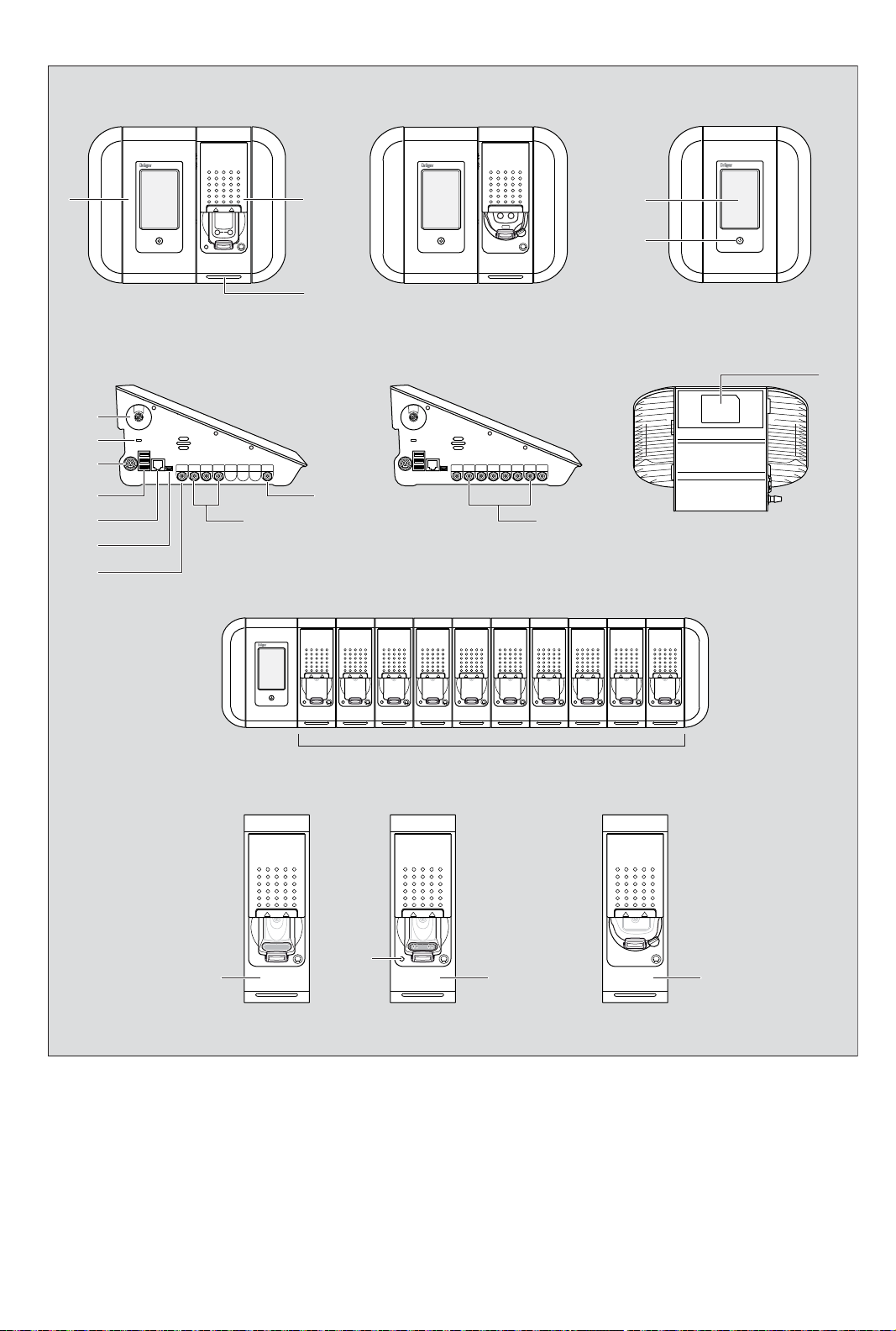
2.1 Produktübersicht (siehe Ausklapper)
1Master
2 Modul
3 Status-LED
4 Touchscreen-Display
5 Funktionstaste
6 Frischlufteinlass mit Frischluftfilter
7 Diebstahlsicherungs-Slot
8 Stromversorgung
9 USB-Anschlüsse
10 Ethernet-Anschluss
11 Mini-USB-Anschluss
12 Gasauslass
13 Gaseinlässe
14 Drucklufteinlass
15 Typenschild
16 X-am 125 Modul
17 Ladezustand-LED
18 X-am 125+ Modul (mit Ladefunktion)
19 Pac-Modul
2.2 Funktionsbeschreibung
2.2.1 Master
Der Master übernimmt für die Wartungsstation die Ablaufsteuerung zum Funktionstesten, Kalibrieren, Justieren sowie Funktionen zur Benutzerverwaltung, Geräteverwaltung, zum
Drucken von Standardberichten und Standardzertifikaten (nur
mit PostScript-Druckern) sowie die Schnittstelle zum Nutzer.
2.2.2 Module
In die Module sind die gerätspezifischen Schnittstellen, wie
z. B. IR-Kommunikation, Begasungseinheit und Ladekontakt
integriert. Zusätzlich beinhalten die Module Sensorik für die
Detektion des optischen, akustischen Alarms und des Vibrationsalarms der Geräte.
2.3 Verwendungszweck
Dräger X-dock 5300/6300/6600 ist eine modular aufgebaute
Wartungsstation. Mit der X-dock können automatisierte Kalibrierungen, Justierungen und Begasungstests von tragbaren
Gasmessgeräten parallel und unabhängig voneinander durchgeführt werden. Ein System besteht aus einem Master für 3
(X-dock 5300/6300) oder 6 (X-dock 6600) Prüfgase. Die
X-dock 5300 umfasst einen Master inklusive einem Modul und
ist nicht erweiterbar. An den Master der X-dock 6300 und 6600
können bis zu 10 Module angeschlossen werden. Die Module
erkennen automatisch wann ein Gerät eingelegt wurde und regeln die Gaszufuhr, so dass jederzeit eine entsprechende
Gasversorgung des Geräts gewährleistet ist.
4 Dräger X-dock 5300/6300/6600
Page 5
Installation
i
i
i
i
i
i
Folgende Gasmessgeräte können mit der X-dock und den entsprechenden Modulen verwendet werden:
X-dock 5300/6300/6600
mit Pac-Modul: mit X-am 125 (+) Modul:
Dräger Pac 3500
Dräger Pac 5500
Dräger Pac 7000
Dräger X-am 1700
Dräger X-am 2000
Dräger X-am 2500
Dräger X-am 5000
Dräger X-am 5600
2.4 GPL (General Public License)
Teile der Gerätesoftware nutzen Open-Source Software, die
unter GPL, LGPL oder einer anderen Open Source Lizenz veröffentlicht wurden. Es handelt sich im Einzelnen um GPL
GPLv2, LGPL, MIT, PostgreSQL, Apache, Apache 2, zlib. Die
Quelltexte der verwendeten Software können für einen Zeitraum von mindestens drei Jahren nach Erwerb des die Software beinhaltenden Produkts auf Datenträger CD unter
Angabe der Materialnummer 83 21 874 über Dräger bezogen
werden. Die jeweiligen Lizenzbestimmungen der benannten
Software liegen auf CD bei.
3 Installation
HINWEIS
Auf ausreichenden Platz für den Gesamtaufbau
achten.
Der Master und alle Module müssen die gleiche Firmware-Version haben. Wenn dies nicht der Fall ist,
muss ein Firmware-Update durchgeführt werden (siehe Kapitel 6.2 auf Seite 12).
1. Ggf. Module entsprechend der dazugehörigen Montageanweisung an den Master montieren (nur bei X-dock 6300/
6600).
Maximal 10 Module können an einen Master montiert
werden.
Die verfügbaren Module können beliebig kombiniert
werden.
2. Ggf. Wand- oder Flaschenhalterung entsprechend der dazugehörigen Montageanweisung montieren.
3. Tüllen von den vorgesehenen Gaseinlässen und vom
Gasauslass entfernen.
HINWEIS
Wenn die Tülle vom Gasauslass nicht entfernt wird,
kann die Station den Selbsttest nicht fehlerfrei durchführen.
4. Gaszufuhrschläuche auf die Gaseinlässe des Master stecken und mit dem Druckregelventil der Prüfgasflasche verbinden.
HINWEIS
Dräger empfiehlt, eine Schlauchlänge von 10 m für die
Gaszufuhrschläuche nicht zu überschreiten.
5. Ggf. Abgasschlauch (max. 10 m Länge) an Gasauslass
anschließen.
6. Druckluft- oder Frischluftzufuhr sicherstellen:
Druckluftschlauch an Druckluftanschluss anschließen
(Ausgangsdruck des Druckregelventils 0,5 bar, Volumenstrom >3 L/min).
ODER
Ggf. Frischluftschlauch an Frischluftfilter anschließen.
7. Netzteil anschließen.
Station mit bis zu 3 Modulen: Netzteil 24 V / 1,33 A
Station mit 4 bis 10 Modulen: Netzteil 24 V / 6,25 A
Das gesamte System wird über den Master mit Strom versorgt.
HINWEIS
i
i
Dräger empfiehlt Dräger-Prüfgasflaschen und DrägerDruckregelventile (siehe Bestellliste) zu verwenden.
Alternativ besteht die Möglichkeit ein passendes
Druckregelventil mit 0,5 bar Ausgangsdruck und
>3 L/min Volumenstrom zu verwenden.
Dräger empfiehlt einen Abgasschlauch (max. 10 m
Länge) an den Gasauslass anzuschließen und mit diesem das Prüfgas ins Freie zu leiten.
4 Grundlagen
4.1 Station ein- oder ausschalten
HINWEIS
i
i
Wenn für 10 Minuten keine Aktion erfolgt, wechselt die
Station automatisch in den Standby-Modus.
Um die Station einzuschalten:
Taste am Master für ca. 1 Sekunde gedrückt halten.
Während des Einschaltprozesses werden folgende Informationen angezeigt:
Software-Versionsnummer
Um die Station auszuschalten:
Taste am Master für ca. 3 Sekunden gedrückt halten.
Die Station schaltet aus.
Standby-Modus:
Der Standby-Modus wird nach ca. 10 Minuten ohne Aktivi-
täten an der Station (Eingabe über Touchscreen-Bildschirm
oder Öffnen/Schließen einer Modulklappe) aktiviert.
Wenn die Station in den Standby-Modus wechselt, wird ein
ggf. angemeldeter Benutzer automatisch abgemeldet. Bei
Wechsel in den Betriebsmodus muss sich der Benutzer
neu anmelden.
Der Touchscreen-Bildschirm wird während des Standby-
Modus ausgeschaltet.
Das Ladeverhalten der X-am 125+ Module mit Ladefunkti-
on wird durch den Standby-Modus nicht betroffen. Ladungen werden weiter durchgeführt.
Um in den Betriebsmodus zu wechseln:
Funktionstaste kurz betätigen oder
Touchscreen berühren oder
Dräger X-dock 5300/6300/6600 5
Page 6
Grundlagen
i
i
eine Modulklappe öffnen oder schließen.
4.2 Ersteinrichtung der Station
1. Station einschalten, siehe Kapitel 4.1 auf Seite 5.
2. Mit dem vorkonfigurierten Benutzer “admin” anmelden
(Benutzername: admin, Kennwort: 123456), siehe
Kapitel 4.5 auf Seite 6.
3. Prüfgaseinlass konfigurieren, siehe Kapitel 4.6 auf Seite 7.
4. Ggf. Sprache ändern:
a. > Systemkonfiguration > Sprache wählen.
b. Gewünschte Sprache auswählen.
c. Auswahl mit OK bestätigen.
5. Ggf. Datum und Uhrzeit einstellen:
a. > Systemkonfiguration > Datum & Uhrzeit wäh-
len.
b. Gewünschte Einstellungen vornehmen.
c. Einstellungen mit OK bestätigen.
4.3 Touchscreen-Bildschirm
Die Schaltflächen des Touchscreen-Bildschirms verändern
sich dynamisch abhängig von der gerade ausgeführten Aufgabe. Zum Ausführen einer Aktion das entsprechende Symbol
auf dem Display wählen.
Es kann jederzeit die Taste am Master gedrückt werden, um
zum Startbildschirm zu gelangen.
4.4 Start- und Testbildschirme
4.5 Benutzer an- oder abmelden
HINWEIS
i
i
Zum Anmelden wird eine Benutzer-ID benötigt. Diese
muss durch den Administrator vorher angelegt
werden.
Standardmäßig ist ein Benutzer mit Administratorrechten angelegt:
Benutzername: admin
Kennwort: 123456
HINWEIS
Dräger empfiehlt nach der Erstinbetriebnahme das
Kennwort des voreingestellten Benutzers “admin” zu
ändern.
Um einen Benutzer anzumelden:
1. wählen.
a. auswählen.
b. Gewünschten Benutzernamen aus der Liste auswäh-
len.
oder
a. Benutzer wählen auswählen.
b. Namen des gewünschten Benutzers eingeben.
2. Kennwort eingeben und mit bestätigen.
Die Schaltflächen der Start- und Testbildschirme verändern
sich dynamisch abhängig vom Anmelde-, Einzelmodus-Zustand und der Anzahl der verwendeten Module. Für weitere Informationen siehe Technisches Handbuch X-dock 5300/6300/
6600.
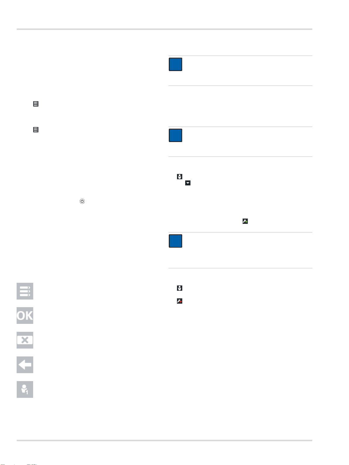
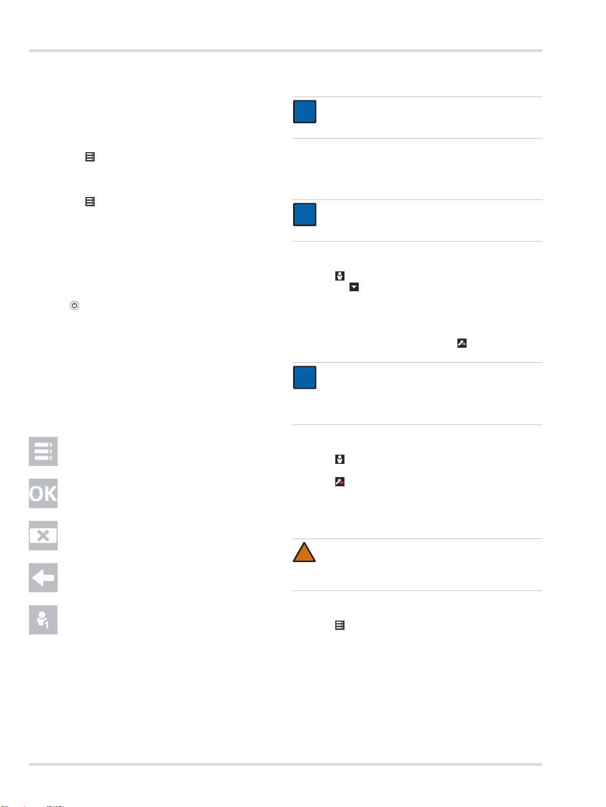
4.4.1 Symbole
Menü Diese Schaltfläche wählen, um
Bestätigen Diese Schaltfläche wählen, um
Abbrechen Diese Schaltfläche wählen, um
Zurück Diese Schaltfläche wählen, um
Benutzer an- oder
abmelden
in das Menü zu gelangen.
eine Eingabe oder Funktion zu
bestätigen.
eine Eingabe oder Funktion
abzubrechen.
zum vorherigen Bildschirm zu
gelangen.
Diese Schaltfläche wählen, um
Benutzer an- oder abzumelden.
Die Zahl im Symbol gibt die
jeweilige Berechtigungsstufe an
(siehe Kapitel 6 auf Seite 11).
HINWEIS
i
i
Während der Eingabe des Benutzernamens werden
automatisch 3 Suchvorschläge von gespeicherten
Benutzernamen angezeigt. Zur Schnellauswahl den
gewünschten Benutzernamen auswählen.
Um den aktuellen Benutzer abzumelden:
1. wählen.
Informationen zum aktuellen Benutzer werden angezeigt.
2. wählen.
Der aktuelle Benutzer wird abgemeldet.
6 Dräger X-dock 5300/6300/6600
Page 7
Grundlagen
!
i
i
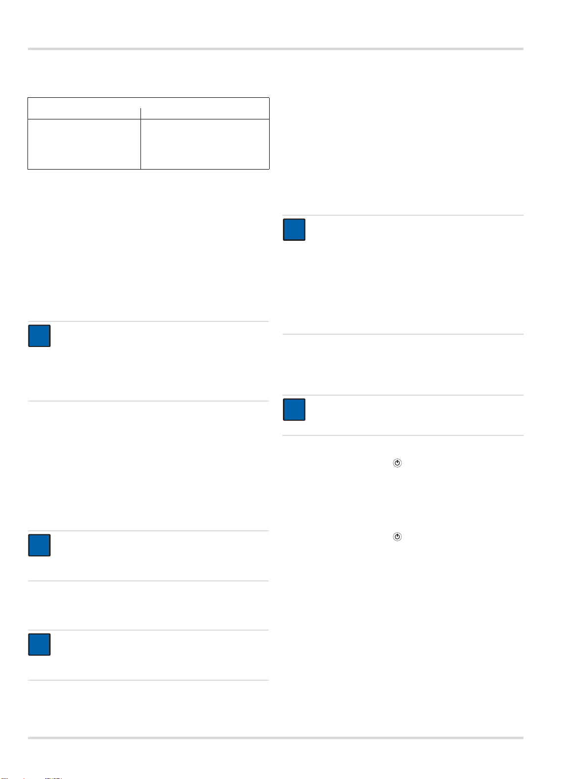
4.6 Prüfgaseinlass konfigurieren
WARNUNG
Die eingetragenen Prüfgaskonzentrationen müssen
identisch mit den Angaben auf der verwendeten Prüfgasflasche sein. Bei falschen Angaben kommt es zu
fehlerhaften Messergebnissen.
Um einen Prüfgaseinlass zu konfigurieren:
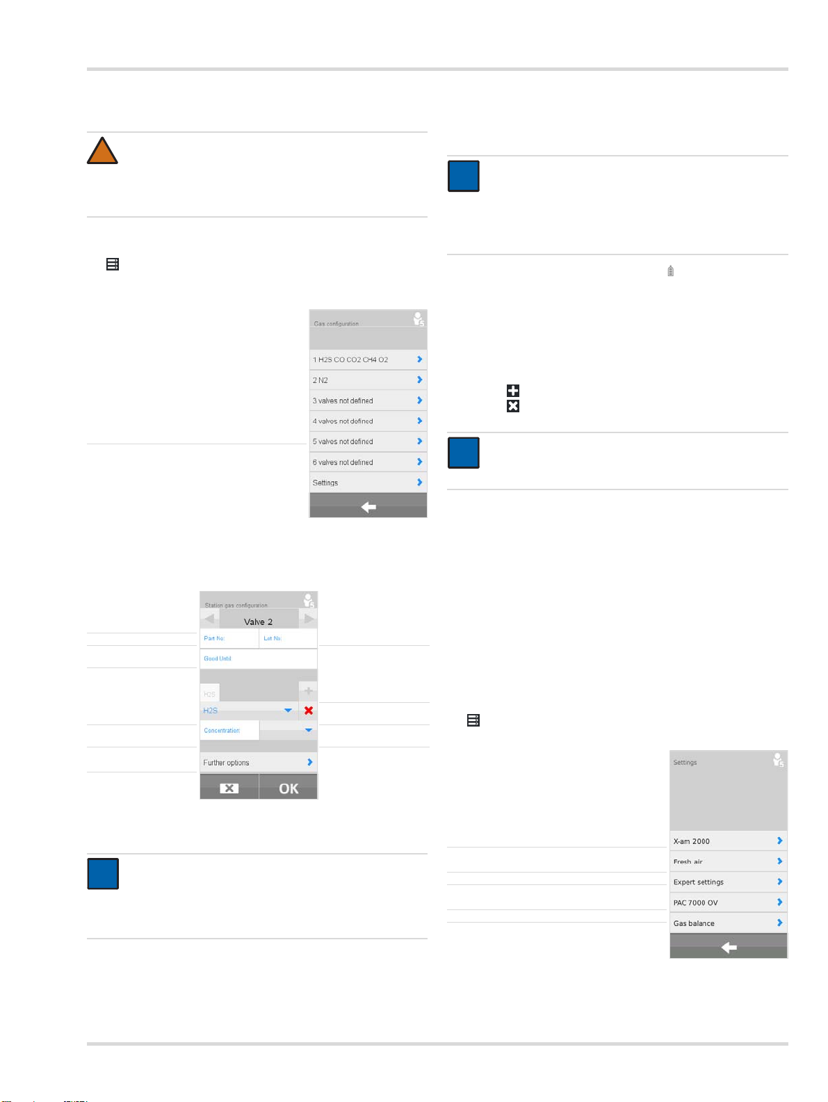
1. > Prüfgaskonfig. d. Station wählen.
Die Übersicht der Prüfgasanschlüsse wird angezeigt.
Prüfgaseinlass auswählen ►
Alle notwendigen Angaben für die Konfiguration werden
automatisch ausgefüllt. Die Losnummer und das Verfallsdatum können zusätzlich manuell eingetragen werden.
HINWEIS
i
i
Die automatisch eingetragenen Werte müssen mit den
Angaben auf der Prüfgasflasche abgeglichen werden.
Wenn sich die Werte unterscheiden, gelten die Angaben auf der Prüfgasflasche und die Werte müssen manuell korrigiert werden.
2. Ggf. Weitere Optionen wählen und wählen, um die Fla-
schenfüllstandskontrolle zurückzusetzen.
3. Ggf. weitere Prüfgaseinlässe auf gleiche Weise konfigurieren.
Bei Verwendung einer Prüfgasflasche eines anderen Herstellers:
1. Prüfgaskomponente anlegen oder löschen.
Mit eine neue Prüfgaskomponente anlegen.
Mit die aktuelle Prüfgaskomponente löschen.
HINWEIS
i
i
Durch Löschung aller Prüfgaskomponenten werden
alle Angaben des Prüfgaseinlasses gelöscht.
2. Gewünschten Prüfgaseinlass auswählen.
Das Konfigurationsmenü erscheint.
Prüfgaseinlass
auswählen
Sachnr. eingeben ►◄Losnr. eingeben
Verfallsdatum
eingeben
Prüfgas
auswählen
Konzentration
eingeben
Weitere Optionen ►
►
►
Prüfgaskomponente
◄
►◄Konfiguration
►◄Einheit
anlegen
löschen
auswählen
Bei Verwendung einer Dräger-Prüfgasflasche:
HINWEIS
Bei Eingabe einer Sachnummer einer Dräger-Prüfgasflasche wird automatisch die Flaschenfüllstandskontrolle angezeigt, sofern diese nicht deaktiviert wurde
(siehe Kapitel 4.6.1 auf Seite 7).
2. Prüfgas auswählen.
3. Prüfgaskonzentration eingeben.
4. Prüfgaseinheit auswählen.
5. Ggf. weitere Prüfgaskomponenten anlegen.
6. Folgende Informationen können optional angegeben werden:
Sachnummer der Prüfgasflasche
Losnummer der Prüfgasflasche
Verfallsdatum der Prüfgasflasche
7. Ggf. Weitere Optionen angeben.
8. Für weitere Informationen siehe Technisches Handbuch
X-dock 5300/6300/6600.
4.6.1 Einstellungen
1. > Prüfgaskonfig. d. Station > Einstellungen wählen.
Prüfgas für X-am 2000 auswählen ►
Einstellung des Frischlufteingangs ►
Experten-Einstellungen ►
Prüfgas für Pac 7000 OV auswählen ►
Flaschenfüllstandskontrolle ►
1. Sachnummer der Dräger-Prüfgasflasche eingeben.
Dräger X-dock 5300/6300/6600 7
Page 8
Grundlagen
i
i
Für das Pac 7000 OV kann für den OV-Sensor zwischen 2 verschiedenen Prüfgasen gewählt werden, die auch für die Justierung und den Test eingesetzt werden. Es stehen
Kohlenstoffmonoxid (CO) und Ethylenoxyde (EO) zur Auswahl.
Für das X-am 2000 kann zwischen 3 verschiedenen Prüfgasen gewählt werden, die auch für die Justierung und den Test
eingesetzt werden. Es stehen Methan (CH
und Pentan (C
ist der Sensor unterschiedlich empfindlich justiert. Nähere Informationen hierzu sind den jeweiligen Sensordatenblättern zu
entnehmen.
HINWEIS
Das entsprechende Gas muss an einem der Gaseinlässe angeschlossen und in der Gaskonfiguration
eingestellt sein.
Zusätzlich besteht die Möglichkeit bei Propan und Pentan eine
Option für „erhöhte Empfindlichkeit“ zu setzen. Durch diese
Option wird künstlich die Empfindlichkeit erhöht, um Sensoren
so zu justieren, dass diese ungefähr eine Nonan-Empfindlichkeit besitzen (also eine Empfindlichkeit als wären sie mit Nonan justiert worden). Nähere Informationen zum Thema
Querempfindlichkeitsjustierung sind den jeweiligen Sensordatenblättern zu entnehmen.
Um das Prüfgas für X-am 2000 auszuwählen:
1. X-am 2000 wählen.
2. Gewünschtes Prüfgas aus der Liste auswählen.
Zur Auswahl stehen:
Methan - CH
Propan - C
Pentan - PENT
Bei Propan und Pentan kann zusätzlich die Option “Erhöhte Empfindlichkeit” (Dampfempfindlichkeit) aktiviert werden.
3. Auswahl mit OK bestätigen.
) zur Auswahl. Je nach ausgewähltem Gas
5H12
(Standardeinstellung)
4
3H8
), Propan (C3H8)
4
WARNUNG
!
Diese Funktion darf nur durch geschultes und fachkundiges Personal aktiviert werden, da eine falsch gewählte Prüfgaskonzentration zu einem positiven
Testergebnis führen kann, obwohl das Gasmessgerät
zu spät alarmiert.
Um das Testverhalten bei fehlenden Prüfgasen einzustellen:
1. Fehlendes Gas wählen.
2. Checkbox aktivieren (Standardeinstellung: aktiviert).
3. Auswahl mit OK bestätigen.
Mit dieser Funktion kann eingestellt werden, ob ein Test oder
eine Justierung auch dann durchgeführt werden soll, wenn ein
benötigtes Prüfgas nicht angeschlossen ist.
WARNUNG
!
Wenn diese Funktion deaktiviert ist, wird der entsprechende Kanal nicht geprüft bzw. justiert.
Um das Prüfgas für Pac 7000 OV auszuwählen:
1. Pac 7000 OV wählen.
2. Gewünschtes Prüfgas aus der Liste auswählen.
Zur Auswahl stehen:
Ethylenoxid - EO (Standardeinstellung)
Kohlenstoffmonoxid - CO
3. Auswahl mit OK bestätigen.
Um die Flaschenfüllstandskontrolle einzustellen:
HINWEIS
i
i
Die Flaschenfüllstandskontrolle steht nur für Flaschen,
die über eine Dräger Sachnummer konfiguriert werden
zur Verfügung.
Um den Frischlufteingang einzustellen:
1. Frischluft wählen.
2. Pumpe (Frischlufteinlass; Standardeinstellung) oder
Drucklufteinlass wählen.
3. Auswahl mit OK bestätigen.
In den Experten-Einstellung können folgende Einstellungen
vorgenommen werden:
Max. Konzentration für schnellen Begasungstest ignorie-
ren
Testverhalten bei fehlenden Prüfgasen einstellen
Um die von Dräger empfohlene max. zulässige Konzentration
für den schnellen Begasungstest zu ignorieren:
1. Max. Konz. für BTQ ignorieren wählen.
2. Checkbox aktivieren (Standardeinstellung: deaktiviert).
3. Auswahl mit OK bestätigen.
Wird diese Funktion aktiviert, können für den schnellen Begasungstest höhere Prüfgaskonzentrationen als von Dräger
empfohlen verwendet werden.
8 Dräger X-dock 5300/6300/6600
1. Gasfüllstandsüberwachung wählen.
2. Kontrollkästchen Gasfüllstandsüberwachung ein akti-
vieren oder deaktivieren.
3. Auswahl mit OK bestätigen.
Um die Flaschenfüllstandskontrolle für eine neue Prüfgasflasche zurückzusetzen:
1. Neue Prüfgasflasche an Prüfgasanschluss anschließen.
2. > Prüfgaskonfig. d. Station wählen.
3. Gewünschten Prüfgaseinlass auswählen.
4. Weitere Optionen wählen und wählen, um die Fla-
schenfüllstandskontrolle zurück zu setzen.
Page 9
Gebrauch
!
i
i
i
i
00233286.eps
1
2
!
5Gebrauch
WARNUNG
Ein defekter Druckminderer an der Prüfgasflasche
kann zu einem erhöhten Druck in der Station führen.
Dadurch können sich die Prüfgasschläuche lösen und
Prüfgas austreten.
Gesundheitsgefahr! Prüfgas nicht einatmen. Gefahrenhinweise der entsprechenden Sicherheits-Datenblätter beachten. Für Abführung in einen Abzug oder
nach außen sorgen.
HINWEIS
Dräger empfiehlt um Prüfgasverlust zu vermeiden, die
Prüfgasflaschen zu schließen, wenn die Station
längere Zeit unbeaufsichtigt ist.
Geräte- und Kanalfehler können dazu führen, dass eine Justierung nicht möglich ist.
5.1 Sichtprüfung durchführen
Eine Sichtprüfung der Gasmessgeräte vor jedem Einsetzen in
die Station durchführen.
1. Unversehrtheit des Gehäuses, der äußeren Filter und der
Typenschilder prüfen.
2. Batteriekontakte und Sensoreingänge auf Verschmutzungen prüfen.
HINWEIS
Geräte, die die Sichtprüfung nicht bestanden haben,
dürfen nicht in die Station eingelegt werden. Die
Gesamtbewertung des Tests kann sonst nicht korrekt
durchgeführt werden.
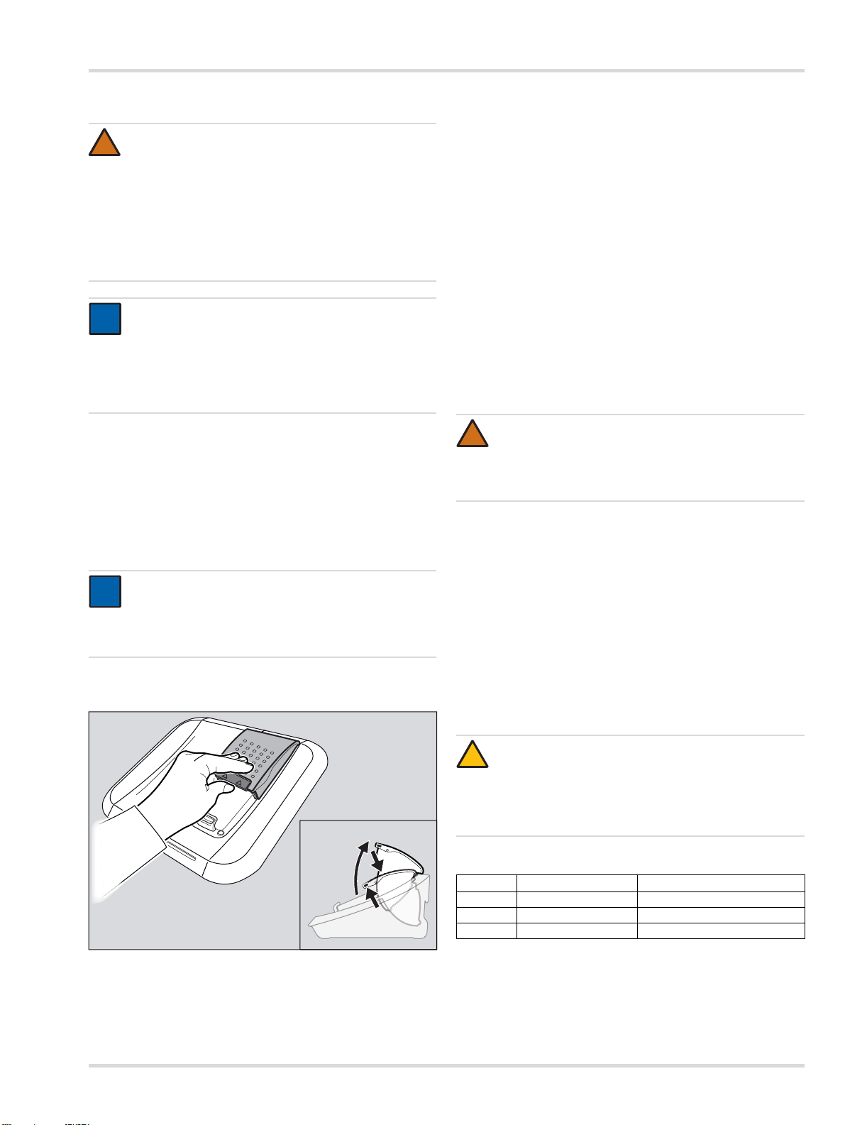
5.2 Gasmessgerät in Modul einsetzen oder
herausnehmen
1. Ggf. Verriegelung leicht nach oben drücken und Modulklappe nach oben öffnen.
2. Gasmessgerät in das entsprechende Modul legen.
3. Modulklappe schließen.
Das Gasmessgerät wird automatisch erkannt.
Nur bei X-am-125+ Modulen mit Ladefunktion:
Nach dem Einlegen des Gasmessgeräts wird der Lade-
zustand für ca. 5 Sekunden durch die LadezustandLED angezeigt.
Die Ladefunktion startet automatisch ca. 15 Minuten
nach dem letzten Test.
Um das Gasmessgerät aus dem Modul herauszunehmen:
1. Verriegelung leicht nach oben drücken und Modulklappe
nach oben öffnen.
2. Gasmessgerät herausnehmen.
5.3 X-am 125+ Modul mit Ladefunktion
(optional)
WARNUNG
Explosionsgefahr! Nicht unter Tage oder in explosionsgefährdeten Bereichen laden. Die X-am 125+ Module mit Ladefunktion sind nicht nach den Richtlinien
für Schlagwetter und Explosionsschutz gebaut.
Ein Laden der Akkus der Gasmessgeräte ist nur mit dem
X-am 125+ Modul mit Ladefunktion möglich.
Die Ladezeit beträgt bei vollständig entladenem Akku ca. 4
Stunden.
Eine neue NiMH-Versorgungseinheit erreicht nach 3 vollen
Lade-/Entladezyklen seine volle Kapazität. Gerät nie lange
(max. 2 Monate) ohne Energieversorgung lagern, da sich
die interne Pufferbatterie verbraucht.
Wenn eine Störung vorliegt:
Gerät aus dem Modul herausnehmen und wieder einlegen.
Wenn die Störung dann nicht behoben ist, Modul reparie-
ren lassen.
VORSICHT
!
Ein Kurzschließen der Ladekontakte in den Modulen,
z. B. durch hineingefallene metallische Gegenstände,
führt nicht zu Schäden an der Station, sollte jedoch
wegen möglicher Erhitzungsgefahr und Fehlanzeigen
am Modul vermieden werden.
Übersicht Ladezustand-LED
Farbe Zustand Bedeutung
grün dauerhaft leuchtend Ladezustand 100 %
grün blinkend Akku wird geladen.
rot blinkend Ladefehler
Um das Gasmessgerät in das Modul einzusetzen:
Dräger X-dock 5300/6300/6600 9
Page 10
Gebrauch
!
i
i
X-am 5000
X-dock 5300
0
0
01033286.eps
5.4 Selbsttest der Station
Ein Selbsttest wird durchgeführt:
Beim Start der Station.
Wenn der letzte erfolgreiche Selbsttest länger als 24 Stun-
den her ist und ein Test durchgeführt wird.
Getestet wird die Dichtigkeit der Station, Funktion der Pumpe,
SW-Version der einzelnen Module und des Masters.
5.5 Test durchführen
WARNUNG
Bei Begasung mit Methan, Propan oder Butan im Bereich >100 %UEG muss ein Abgasschlauch (max.
10 m Länge) an dem Gasauslass angeschlossen sein,
um die Absaugung von überschüssigen explosionsfähigem Gas zu gewährleisten.
HINWEIS
Standardmäßig ist der Einzelmodus aktiviert.
Mehrere Tests können parallel im Einzelmodus gestartet und ausgeführt werden.
Ein Fehlschlagen eines LED-, Hupen- oder Vibrationstests führt zu einer negativen Bewertung des Gesamttests und somit zu einer Sperrung des entsprechenden
Gasmessgeräts.
Wenn der Favoritenmodus aktiviert ist:
Gewünschten Test aus der Favoritenleiste wählen.
Der Test wird automatisch gestartet.
Die Status-LED blinkt blau.
Die einzelnen Testphasen werden angezeigt.
Wenn der Testplaner-Modus aktiviert ist:
Ggf. Benutzer an der Station abmelden (siehe Kapitel 4.5
auf Seite 6).
Der voreingestellte Test wird nach dem konfigurierten Zeit-
plan durchgeführt.
Wenn der Log-In Modus aktiviert ist:
Benutzer an der Station anmelden (siehe Kapitel 4.5 auf
Seite 6).
Gewünschten Test aus der Favoritenleiste wählen.
Der Test wird automatisch gestartet.
Die Status-LED blinkt blau.
Die einzelnen Testphasen werden angezeigt.
Test bestanden:
Eine Überprüfung der Sensor-Reserve wird nur bei
Sensoren durchgeführt, die diese Funktion unterstützen. Das Ergebnis wird bei den Testdetails angezeigt
und gibt eine Information über den Zustand des Sensors.
Folgende Tests sind vorkonfiguriert:
Test 1: QUI
Test 2: EXT
Test 3: CAL
Schneller Begasungstest inkl.
Alarmüberprüfung.
Erweiterter Begasungstest inkl.
Nullpunktprüfung und Alarmüberprüfung.
Justierung, Alarmtest, Frischluftspülung und
Zertifikat.
1. Ggf. Prüfgasflaschen öffnen.
2. Ggf. X-dock einschalten.
3. Sichtprüfung der Gasmessgeräte durchführen (siehe
Kapitel 5.1 auf Seite 9).
4. Gasmessgeräte in Module einsetzen (siehe Kapitel 5.2 auf
Seite 9).
Wenn der Einzelmodus aktiviert ist:
Der voreingestellte Test wird durch das Schließen der Mo-
dulklappe automatisch gestartet.
Die Status-LED blinkt blau.
Die einzelnen Testphasen werden angezeigt.
Eine Bestätigung wird auf dem Display angezeigt.
Die Status-LED blinkt grün.
Ggf. gewünschtes Gerätefeld wählen, um weitere Informa-
tionen zu erhalten.
Gasmessgerät aus dem Modul herausnehmen.
10 Dräger X-dock 5300/6300/6600
Page 11
Wartung
X-am 5000
X-dock 5300
0
0
01133286.eps
X-am 5000
X-dock 5300
0
0
01133286.eps
Test bestanden, mit Einschränkungen:
Der Zustand bedeutet, dass Teiltests des Favoriten aufgrund
von speziellen Einstellungen nicht durchgeführt werden konnten.
Eine Bestätigung wird auf dem Display angezeigt.
Die Status-LED blinkt gelb.
Ggf. gewünschtes Gerätefeld wählen, um weitere Informa-
tionen zu erhalten.
Gasmessgerät aus dem Modul herausnehmen.
Test nicht bestanden:
5.6 Nach dem Gebrauch
1. Ggf. Gasmessgeräte aus Modulen herausnehmen.
2. Prüfgasflaschen schließen.
HINWEIS
i
i
Um den Energieverbrauch niedrig zu halten, empfiehlt
Dräger das Gerät nach Gebrauch entsprechend der
Gebrauchsanweisung auszuschalten.
6 Wartung
6.1 Instandhaltungsintervalle
HINWEIS
i
i
Je nach sicherheitstechnischen Erwägungen,
verfahrenstechnischen Gegebenheiten und
gerätetechnischen Erfordernissen ist die Länge der
Instandhaltungsintervalle auf den Einzelfall
abzustimmen und ggf. zu verkürzen. Dräger empfiehlt
für den Abschluss eines Service-Vertrags sowie für
Instandsetzungen den DrägerService.
6.1.1 Vor jeder Inbetriebnahme
Folgende Arbeiten sind vor jeder Inbetriebnahme des Geräts
durchzuführen:
Verschlauchung auf Verschmutzung, Versprödung und Be-
schädigung prüfen und ggf. auswechseln.
Festen Sitz der Schläuche prüfen, um Gasaustritt zu ver-
meiden.
Anschlüsse aller Kabel auf festen Sitz prüfen.
Sichtkontrolle der Module und Sensorabdichtungen. Bei
starker Verschmutzung oder sichtbaren Defekten muss die
Sensorabdichtung ausgetauscht werden.
6.1.2 Jährlich
Inspektion der gesamten X-dock-Station durch fachkundiges
Personal.
Eine Fehlermeldung wird auf dem Display angezeigt.
Die Status-LED blinkt rot.
Ggf. gewünschtes Gerätefeld wählen, um weitere Informa-
tionen zu erhalten.
Fehler identifizieren und beheben.
Ggf. Test wiederholen.
Übersicht Status-LED
Farbe Zustand Bedeutung
blau blinkend Prozess in Bearbeitung
grün blinkend Test erfolgreich bestanden
gelb blinkend
rot blinkend
Test bestanden,
mit Einschränkungen
Test nicht bestanden/
abgebrochen
Dräger X-dock 5300/6300/6600 11
Page 12
Wartung
!
i
i
!
6.2 Firmware-Update durchführen
VORSICHT
Während des Installationsvorgangs darf die Spannungsversorgung der Station nicht getrennt werden.
Die Station kann sonst beschädigt werden.
HINWEIS
Die Station unterstützt keine USB-Datenspeicher mit
NTFS-Dateisystem.
1. Firmware-Update aus dem Netz herunterladen:
a. www.draeger.com aufrufen.
b. X-dock Produktseite aufrufen und das Firmware-Up-
date auf einen leeren USB-Datenspeicher in das Wurzelverzeichnis (Root-Verzeichnis) entpacken.
VORSICHT
Auf dem USB-Datenspeicher dürfen keine älteren
Firmware-Dateien vorhanden sein!
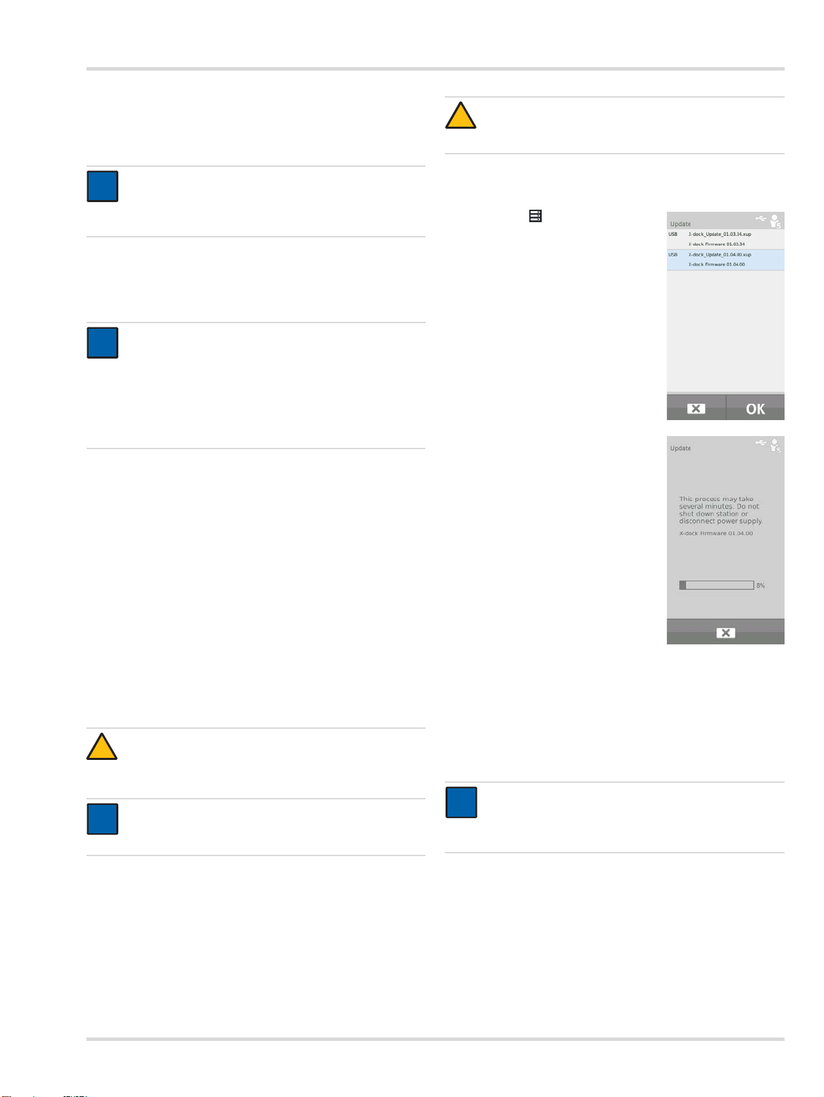
2. USB-Datenspeicher mit Firmware-Update an den USB-Anschluss der Station anschließen.
Das USB-Symbol erscheint in der Statuszeile.
3. > Systemkonfiguration > Up-
date wählen.
Eine Liste mit allen auf dem USBDatenspeicher verfügbaren Firmware-Updates wird angezeigt.
4. Aus der Liste das gewünschte
Firmware-Update auswählen. Das
ausgewählte Firmware-Update
wird blau markiert.
6. Nach erfolgreicher Übertragung auf die Station wird automatisch ein Neustart der Station mit anschließender Installation des Firmware-Updates durchgeführt. Während des
Installationsvorgangs leuchten die Status-LEDs der Module weiß.
7. Nach erfolgreicher Installation wechselt die Station in den
Betriebsmodus. Die Station ist betriebsbereit.
5. Firmware-Update mit OK starten.
Der Fortschritt der Installation wird
angezeigt..
12 Dräger X-dock 5300/6300/6600
Page 13
Entsorgung
i
i
00633286.eps
00733286.eps
6.3 Dichtungseinsatz wechseln
HINWEIS
Die Dichtungseinsätze müssen in regelmäßigen
Abständen (z. B. bei jeder Inspektion) gewechselt
werden oder je nach Bedarf früher.
6.4 Frischluftfilter wechseln
HINWEIS
i
i
Der Frischluftfilter muss bei regelmäßiger Nutzung und
abhängig von den Einsatzbedingungen typisch alle
2 Monate gewechselt werden.
1. Alten Frischluftfilter abschrauben.
2. Neuen Frischluftfilter aufschrauben.
6.5 Touchscreen kalibrieren
1. Beim Starten der Anlage die Funktionstaste gedrückt halten bis die Kalibrieranzeige angezeigt wird.
2. Jeweils auf die 5 nacheinander angezeigten Positionsmarkierungen drücken.
6.6 Reinigung
VORSICHT
!
Raue Reinigungsgegenstände (Bürsten usw.), Reinigungsmittel und Lösungsmittel können den Frischluftfilter zerstören.
Das Gerät bedarf keiner besonderen Pflege.
Bei starker Verschmutzung kann das Gerät vorsichtig mit
einem feuchten Tuch abgewischt werden.
Gerät mit einem Tuch abtrocknen.
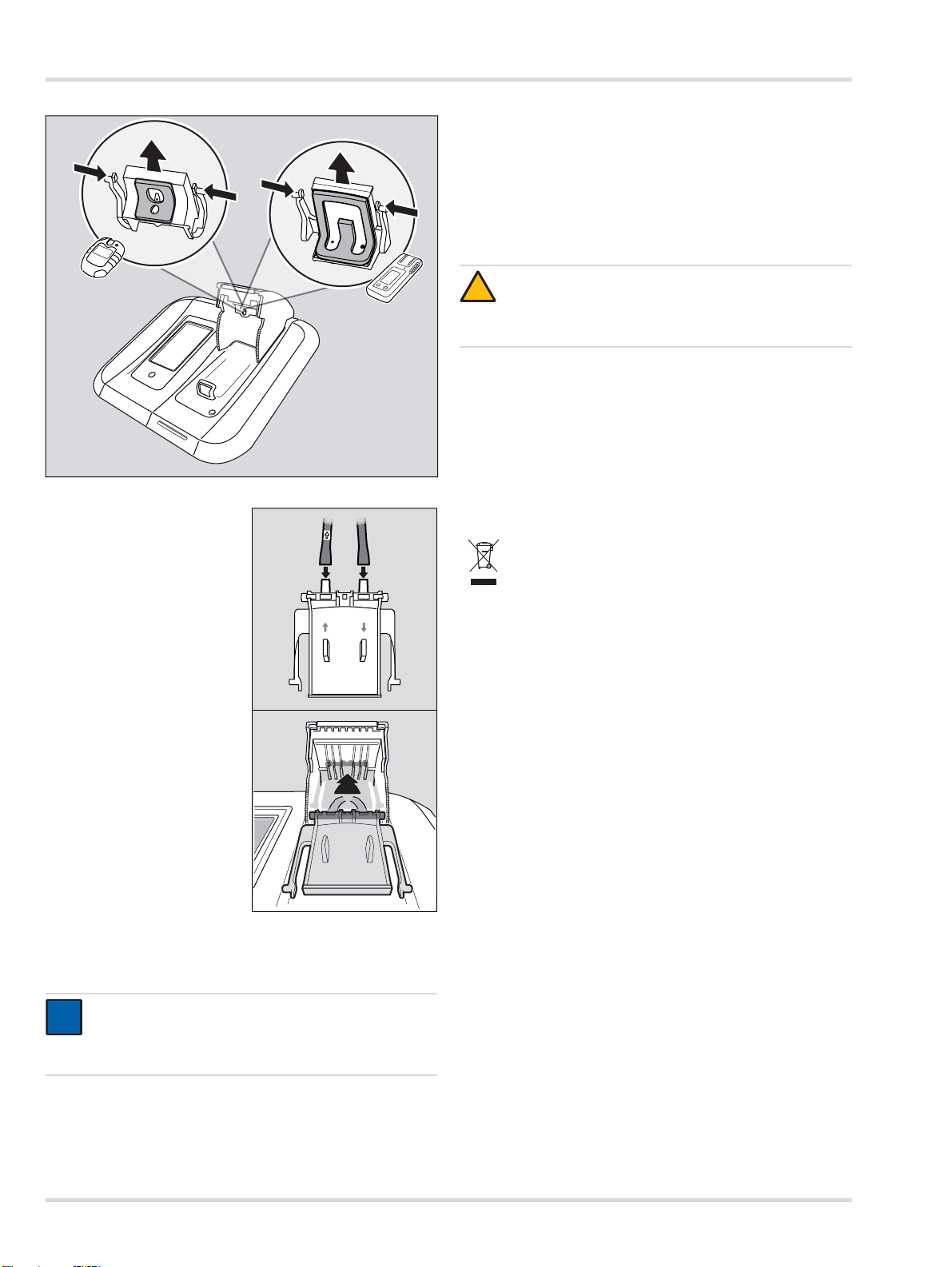
1. Modulklappe öffnen.
2. Beide äußeren Verriegelungsnasen nach innen
drücken und Dichtungseinsatz nach unten herausziehen.
3. Schläuche vom Dichtungseinsatz lösen.
4. Dichtungseinsatz austauschen.
5. Schläuche an neuen Dichtungseinsatz stecken
(Pfeile auf Dichtungseinsatz und Schlauch beachten).
6. Äußere Verriegelungsnasen nach innen drücken
und Dichtungseinsatz so in
die Modulklappe einsetzten, bis die Verriegelungsnasen einrasten.
7. Dichtungseinsatz auf korrekten Sitz in der Modulklappe prüfen.
7Entsorgung
Produkt gemäß den geltenden Vorschriften entsorgen.
Entsorgung von Elektro- und Elektronikgeräten:
Gemäß Richtlinie 2002/96/EG darf dieses Produkt
nicht als Siedlungsabfall entsorgt werden. Es ist
daher mit dem nebenstehenden Symbol
gekennzeichnet.
Dräger nimmt dieses Produkt kostenlos zurück. Informationen dazu geben die nationalen Vertriebsorganisationen und Dräger.
Dräger X-dock 5300/6300/6600 13
Page 14
Technische Daten
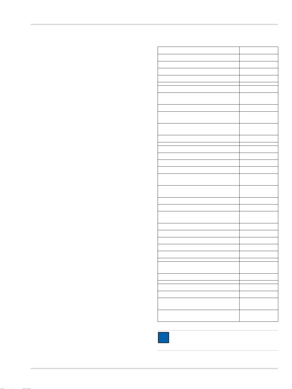
8 Technische Daten 9 Bestellliste
Maße (H x B x T):
Master ca. 120 x 130 x 250 mm
Modul ca. 90 x 145 x 250 mm
Gewicht:
Master ca. 1500 g
Modul ca. 960 g
Umweltbedingungen:
bei Betrieb
bei Lagerung
Gasanschlüsse: 1x Frischluftanschluss
X-dock 5300/6300 3x Gaseinlass
X-dock 6600 6x Gaseinlass
Eingangsdruck:
für Messgas 0,5 bar ±20 %
für Druckluft 0,5 bar ±20 %
Stromversorgung: 11 V - 28 V Gleichspannung,
Anschlüsse: 3x USB 2.0 Standard-A-
Serien-Nr. (Baujahr): Das Baujahr ergibt sich aus dem
CE Kennzeichnung: Elektromagnetische
0°C bis +40°C
-20 °C bis +50 °C
700 bis 1300 hPa
max. 95% relative Feuchtigkeit
1x Drucklufteinlass
1x Gasauslass
6,25 A
Anschluss, (Host, Kabel <3 m)
1x USB 2.0 Mini-B-Anschluss,
(Device, Kabel <3 m)
1x Ethernet-Anschluss RJ45
Datenübertragungsrate
10/100 Mbit
3. Buchstaben der auf dem
Typenschild befindlichen
Fabriknummer: B=2010, C=2011,
D=2012, E=2013, F=2014,
G=2015, H=2016, usw.
Beispiel: Seriennummer ARFH0054, der 3. Buchstabe ist F, also
Baujahr 2014.
Verträglichkeit (Richtlinie 2004/
108/EG)
Benennung und Beschreibung
Dräger X-dock 5300 X-am 125 83 21 880
Dräger X-dock 5300 Pac 83 21 881
Dräger X-dock 6300 Master 83 21 900
Dräger X-dock 6600 Master 83 21 901
Dräger X-dock Modul X-am 125 83 21 890
Dräger X-dock Modul X-am 125+
(mit Ladefunktion)
Dräger X-dock Modul Pac 83 21 892
Dräger X-dock Modul X-am 125,
AA-Version
Dräger X-dock Modul X-am 125+,
AA-Version (mit Ladefunktion)
Dräger X-dock Modul Pac,
AA-Version
Wandhalterung einfach 83 21 922
Wandhalterung komfort 83 21 910
Flaschenhalterung (Tischvariante) 83 21 918
Flaschenhalterung für Hutschiene 83 21 928
Netzteil 24 V / 1,33 A (bis zu 3 Module) 83 21 849
Netzteil 24 V / 6,25 A (bis zu 10 Module) 83 21 850
KFZ-Adapter X-dock 83 21 855
Druckregelventil 0,5 bar 83 24 250
Set Pumpenfilter (besteht aus Filter und
einer Schlauchanschlusstülle)
Fluorkautschukschlauch 12 03 150
Dichtungseinsatz (X-am) 83 21 986
Dichtungseinsatz (Pac) 83 21 987
Displayschutzfolie X-dock Master 83 21 804
Aufkleber für Modulnummerierung 83 21 839
Barcode-Etikette außen
(22 x 8 mm, 500 Stk.)
Barcode-Scanner 83 18 792
Dräger X-dock Manager Basic 83 21 860
Dräger X-dock Manager Professional 83 21 870
Dräger X-dock Manager Lizenz
(1x, beide Versionen)
Dräger X-dock Manager Lizenz
(5x, beide Versionen)
HINWEIS
i
i
Dräger empfiehlt Dräger-Prüfgasflaschen zu
verwenden.
Bestellnr.
83 21 891
83 24 260
83 24 261
83 24 262
83 19 364
AG02551
83 21 857
83 21 858
14 Dräger X-dock 5300/6300/6600
Page 15

10 Glossar
Abkürzung Erklärung
ALARM Alarmelementetest
BTQ Schneller Begasungstest
BTX Erweiterter Begasungstest
CAL Justierung
DB Datenbank
DBMS Datenbankmanagementsystem
DL Datenlogger
FAV Favorit
HORN Hupe
LED Leuchtdiode
LEL Untere Explosionsgrenze
MSD Massenspeichergerät
MST Master
SPAN Empfindlichkeitsjustierung
SW Software
T90 Ansprechzeitentest
TWA Schichtmittelwert
UNDEF Unbekannt
UNK Unbekannte Angabe
VIB Vibration
ZCHECK Nullpunktprüfung
ZERO Nullpunktjustierung
Glossar
Dräger X-dock 5300/6300/6600 15
Page 16
For your safety
!
!
i
i
1 For your safety
1.1 General safety notes
Before using this product, carefully read the Instructions for
Use.
Strictly follow the Instructions for Use. The user must fully
understand and strictly observe the instructions. Use the
product only for the purposes specified in the Intended use
section of this document.
Do not dispose of the Instructions for Use. Ensure that they
are retained and appropriately used by the product user.
Only trained and competent users are permitted to use this
product.
Comply with all local and national rules and regulations
associated with this product.
Only trained and competent personnel are permitted to
inspect, repair and service the product. Dräger recommend
a Dräger service contract for all maintenance activities and
that all repairs are carried out by Dräger.
Only trained and competent personnel are permitted to
inspect, repair and service the product as detailed in these
Instructions for Use.
Use only genuine Dräger spare parts and accessories, or
the proper functioning of the product may be impaired.
Do not use a faulty or incomplete product. Do not modify
the product.
Notify Dräger in the event of any component fault or failure.
1.2 Definitions of alert icons
The following alert icons are used in this document to provide
and highlight areas of the associated text that require a greater
awareness by the user. A definition of the meaning of each
icon is as follows:
WARNING
Indicates a potentially hazardous situation which, if not
avoided, could result in death or serious injury.
CAUTION
Indicates a potentially hazardous situation which, if not
avoided, could result in physical injury, or damage to
the product or environment. It may also be used to
alert against unsafe practices.
NOTICE
Indicates additional information on how to use the
product.
2 Description
2.1 Product overview (see fold-out section)
1Master
2 Module
3 Status LED
4 Touchscreen display
5 Function key
6 Fresh air inlet with filter
7 Antitheft slot
8 Power supply
9USB ports
10 Ethernet port
11 Mini USB port
12 Exhaust
13 Gas inlets
14 Compressed air inlet
15 Type plate
16 X-am 125 module
17 Charge status LED
18 X-am 125+ module (with charging function)
19 Pac module
2.2 Feature description
2.2.1 Master
The master assumes control of the sequencing of the
maintenance station for functional testing, calibration and
adjustment, as well as functions for user management,
instrument management, printing of standard reports and
standard certificates (using PostScript printers only), and also
the user interface.
2.2.2 Modules
The instrument-specific interfaces such as, e. g., IR
communication, gas exposure unit and charging contact are
integrated into the modules. In addition, the modules contain
sensors for detecting the visual, audible and vibration alarms
on the instruments.
2.3 Intended use
The Dräger X-dock 5300/6300/6600 is a maintenance station
of modular construction. The X-dock can be used to perform
automated calibrations, adjustments and bump tests on
portable gas monitors in parallel and independently from one
another. A system consists of one master for 3 (X-dock 5300/
6300) or 6 (X-dock 6600) test gases. The X-dock 5300
consists of a master station with one module and cannot be
expanded. Up to 10 modules can be connected to the X-dock
6300 and 6600 master. The modules automatically detect
when an instrument has been inserted and control the gas
supply so that an appropriate supply to the instrument is
ensured at all times.
16 Dräger X-dock 5300/6300/6600
Page 17
Installation
i
i
i
i
i
i
The following gas measuring devices can be used with the
X-dock and its modules:
X-dock 5300/6300/6600
with Pac module: with X-am 125 (+) module:
Dräger Pac 3500
Dräger Pac 5500
Dräger Pac 7000
Dräger X-am 1700
Dräger X-am 2000
Dräger X-am 2500
Dräger X-am 5000
Dräger X-am 5600
2.4 GPL (General Public Licence)
Some of the device software includes open-source software,
which has been published under GPL, LGPL or another opensource licence. They include GPL GPLv2, LGPL, MIT,
PostgreSQL, Apache, Apache 2, zlib. The source texts of the
software can be obtained from Dräger on a CD under material
number 83 21 874 for at least three years after purchase of the
software. The licence terms and conditions of the software are
included on CD.
3 Installation
NOTICE
Ensure adequate space for the entire assembly.
The master and all modules must have the same
firmware version. If this is not the case, a firmware
update needs to be carried out (see chapter 6.2 on
page 23).
Connect the compressed air hose to the compressed
air port (outlet pressure of pressure regulator valve
0.5 bar, flow rate >3 l/min).
OR
If required, connect the fresh air hose to the fresh air
filter.
7. Connect the power pack.
Station with up to 3 modules: Power pack 24 V / 1.33 A
Station with 4 to 10 modules: Power pack 24 V / 6.25 A
The entire system is supplied with power via the master.
NOTICE
i
i
Dräger recommends the use of Dräger gas cylinders
and Dräger pressure regulator valves (see order list).
Alternatively there is the option of using a suitable
pressure regulator valve with 0.5 bar outlet pressure
and >3 l/min flow rate.
Dräger recommends connecting an exhaust hose
(max. 10 m long) to the exhaust outlet to discharge the
test gas into the open air.
4Basics
4.1 Switching the station on or off
NOTICE
i
i
If no action has occurred for 10 minutes, the station
switches automatically to standby mode.
1. If applicable, install modules on the master station in
accordance with the assembly instructions (X-dock 6300/
6600 only).
A maximum of 10 modules can be installed on one
master station.
The available modules can be combined in any way
desired.
2. If applicable, install wall mount or cylinder holder in
accordance with the assembly instructions.
3. Remove the sleeves from the intended gas inlets and from
the gas outlet.
NOTICE
If the sleeve is not removed from the gas outlet, the
station will be unable to conduct the self-test without
errors.
4. Fit the gas feed hoses to the gas inlets on the master and
connect them to the regulator valve on the test gas
cylinder.
NOTICE
Dräger recommends not exceeding a hose length of
10 m for the gas feed hoses.
5. If required, connect an exhaust hose (max. 10 m long) to
the exhaust outlet.
6. Ensure a supply of compressed air or fresh air:
To switch the station on:
Press and hold the key on the master for approx.
1 second.
The following information is displayed during the switch-on
process:
Software version number
To switch the station off:
Press and hold the key on the master for approx.
3 seconds.
The station switches off.
Standby mode:
Standby mode is activated after approx. 10 minutes with no
activity on the station (input via touchscreen or opening/
closing of a module cover).
When the station switches over to standby mode, any user
logged in will be logged off automatically. The user will need
to log back in again when switching back to operating mode.
The touchscreen is switched off in standby mode.
The charging function of X-am 125+ modules with charging
function is not affected by standby mode. The charging
process is not interrupted.
To switch to operating mode:
Tap the function key or
touch the touchscreen or
open or close a module flap.
Dräger X-dock 5300/6300/6600 17
Page 18
Basics
4.2 Initial setup of station
1. Switch on the station, see chapter 4.1 on page 17.
2. Log in with the preconfigured "admin" user
(user name: admin, password: 123456), see chapter 4.5
on page 18.
3. Configure the test gas inlet, see chapter 4.6 on page 18.
4. Change language if necessary:
a. Select > System configuration > Language.
b. Selected the required language.
c. Confirm selection with OK.
5. Set date and time where necessary:
a. Select > System configuration > Date & time.
b. Make the desired settings.
c. Confirm settings with OK.
4.3 Touchscreen display
The buttons on the touchscreen display change dynamically
depending on the task being executed. To execute an action,
select the corresponding icon on the display.
Press the key on the master at any time to access the start
screen.
4.4 Start and test screens
The keys on the start and test screen change dynamically
depending on the log-in status, single-mode status and the
number of modules in use. For more information see the Xdock 5300/6300/6600 Technical Manual.
4.4.1 Symbols
4.5 Log user in or out
NOTICE
i
i
A User-ID is required to log in. This must be created
beforehand by the Administrator.
A user with administrator rights is created by default:
User name: admin
Password: 123456
NOTICE
i
i
Dräger recommends changing the admin password
after initial start-up.
To log in a user:
1. Select .
a. Select .
b. Select the desired user name from the list.
or
a. Select Select user.
b. Enter desired user name.
2. Enter the password and confirm with .
NOTICE
i
i
When entering the user name, 3 already saved user
names will automatically be suggested and displayed.
For quick selection, please select the desired user
name.
Menu Select this button to access the
menu.
Confirm Select this button to confirm an
input or function.
Cancel Select this button to cancel an
input or function.
Back Select this button to access the
previous screen.
Log user in or out Select this button to log users in
or out. The number in the
symbol indicates the permission
level (see chapter 6 on
page 23).
To log out the current user:
1. Select .
Information about the current user will be displayed.
2. Select .
The current user will be logged out
4.6 Configuring the test gas inlet
WARNING
!
The gas concentrations entered must be identical to
the specifications on the gas cylinder used. Incorrect
details will result in faulty measurement results.
To configure a gas inlet:
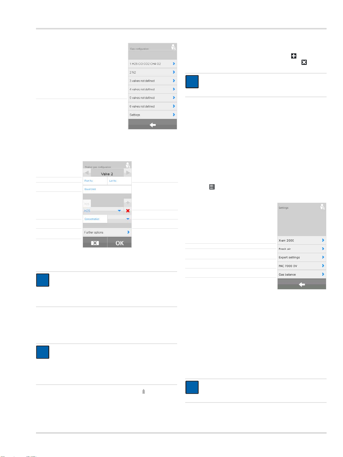
1. Select > Station gas configuration.
An overview of the test gas connections is displayed.
18 Dräger X-dock 5300/6300/6600
Page 19
Select the gas inlet ►
i
i
i
i
2. Select desired gas inlet.
The configuration menu will appear.
Select Test gas inlet
Enter part no. ►◄Enter batch no.
Enter Expiry date
►
►
Basics
When using a gas cylinder from another manufacturer:
1. Create or delete test gas component.
Create a new test gas component with .
Delete the current test gas component with .
NOTICE
i
i
Deleting all test gas components deletes all
information of the test gas inlet.
2. Select gas.
3. Enter the gas concentration.
4. Select gas units.
5. If required, create additional test gas components.
6. The following information can optionally be given:
Part No. of the gas cylinder
Lot number of test gas cylinder
Use-by date of the gas cylinder
7. If required, enter Further options.
8. For more information see the X-dock 5300/6300/6600
Technical Manual.
4.6.1 Settings
1. Select > Station gas configuration > Settings.
Create Test gas
◄
component
Select Test gas
Enter concentration ►◄Select unit
Further options ►
►◄Delete configuration
When using a Dräger gas cylinder:
NOTICE
Upon entering the part no. of a Dräger gas cylinder, a
gas cylinder level indicator is displayed automatically,
unless this function was deactivated before (see
chapter 4.6.1 on page 19).
1. Enter the Part No. of the Dräger gas cylinder.
All the necessary details for the configuration will be
automatically filled in. The batch number and the expiry
date can be entered manually in addition.
NOTICE
The values entered automatically must be matched
with those indicated on the test gas cylinder. If these
values are not identical, the value indicated on the gas
cylinder is to be considered and a manual correction of
the values must be made.
2. If necessary select Further options and , to reset the
gas cylinder level indicator.
3. If required, configure other gas inlets in the same way.
Select test gas for X-am 2000
Fresh air inlet setting ►
Expert settings ►
Select test gas for PAC 7000 OV ►
Gas cylinder level indicator ►
►
The OV sensor of the PAC 7000 OV allows to choose between
two different test gases that are also used for calibration and
testing. These test gases are carbon monoxide (CO) and
ethylene oxide (EO).
For the X-am 2000, it is possible to choose between 3 different
test gases that are also used for calibration and testing. The
three options are methane (CH
pentane (C
sensitivity levels depending on the gas selected. More
). The sensor is calibrated with different
5H12
), propane (C3H8) and
4
information on this can be found in the relevant sensor data
sheets.
NOTICE
i
i
The corresponding gas must be connected to one of
the gas inlets and set in the gas configuration.
Dräger X-dock 5300/6300/6600 19
Page 20
Use
!
There is also the option of setting an "increased sensitivity"
option for propane and pentane. This option artificially
increases the sensitivity to calibrate the sensors so that these
have approximately a nonane sensitivity level (in other words,
a sensitivity level as if they were calibrated for nonane). More
information on the subject of cross-sensitivity calibration can
be found in the relevant sensor data sheets.
To select the test gas for X-am 2000:
1. Select X-am 2000.
2. Select the required test gas from the list.
The following selection is available:
Methane - CH
Propane - C
Pentane - PENT
For propane and pentane, the "Increased sensitivity"
(vapour sensitivity) option can also be activated.
3. Confirm selection with OK .
To set the fresh air input:
1. Select Fresh air.
2. Select pump (fresh air inlet; default setting) or compressed
air inlet.
3. Confirm selection with OK .
The following settings can be made in Expert settings:
Ignore maximum concentration for quick bump test
Set test behaviour for missing test gases
To ignore the max. allowable concentration for the quick bump
test recommended by Dräger:
1. Select Ignore max. conc. for BTQ.
2. Activate checkbox (default setting: deactivated).
3. Confirm selection with OK.
If this function is activated, higher test gas concentrations can
be used for the quick bump test than those recommended by
Dräger.
WARNING
Only trained and experienced personnel are permitted
to activate this function, because an incorrectly
selected test gas concentration may result in a positive
test result even though the instrument alarmed too
late.
To set the test behaviour with missing test gases:
1. Select Missing gas.
2. Activate checkbox (default setting: activated).
3. Confirm selection with OK.
This function can be used to set whether or not a test or
calibration is carried out when a required test gas is not
connected.
(default setting)
4
3H8
WARNING
!
If this function is deactivated, the corresponding
channel is not tested or calibrated.
To select the test gas for PAC 7000 OV:
1. Select Pac 7000 OV.
2. Select the required test gas from the list.
The following selection is available:
Ethylene oxide - EO (default setting)
Carbon monoxide - CO
3. Confirm selection with OK.
To set the gas cylinder level indicator:
NOTICE
i
i
The gas cylinder level indicator is only available for
cylinders that are configured via a Dräger part no.
1. Select Gas level monitoring.
2. Activate or deactivate check box Gas level monitoring
on.
3. Confirm selection with OK.
To reset the gas cylinder level indicator for a new test gas
cylinder:
1. Connect a new test gas cylinder to a test gas connection.
2. > Select Station gas configuration.
3. Select desired gas inlet.
Select Further options and select , to reset the gas cylinder
level indicator.
5Use
WARNING
!
A defective pressure reducer on the gas cylinder can
lead to increased pressure in the station. The gas
hoses may loosen as a result and gas may escape.
Health hazard! Test gas must not be inhaled. Observe
the hazard warnings in the relevant Safety Data
Sheets. Provide venting into a fume cupboard
or outside the building.
NOTICE
i
i
To prevent loss of gas, Dräger recommends closing
the gas cylinders when the station is left unattended for
long periods.
Adjustment may not be possible due to instrument and
channel errors.
5.1 Conducting a visual inspection
A visual inspection of the gas measurement systems should be
conducted every time before being inserted into the station.
1. Check that the housing, external filters and the nameplates
are intact.
20 Dräger X-dock 5300/6300/6600
Page 21
Use
i
i
00233286.eps
1
2
!
2. Check the battery contacts and sensor inputs for dirt.
NOTICE
Devices that have not passed the visual inspection
must not be inserted into the station. Otherwise the
test cannot be fully evaluated correctly.
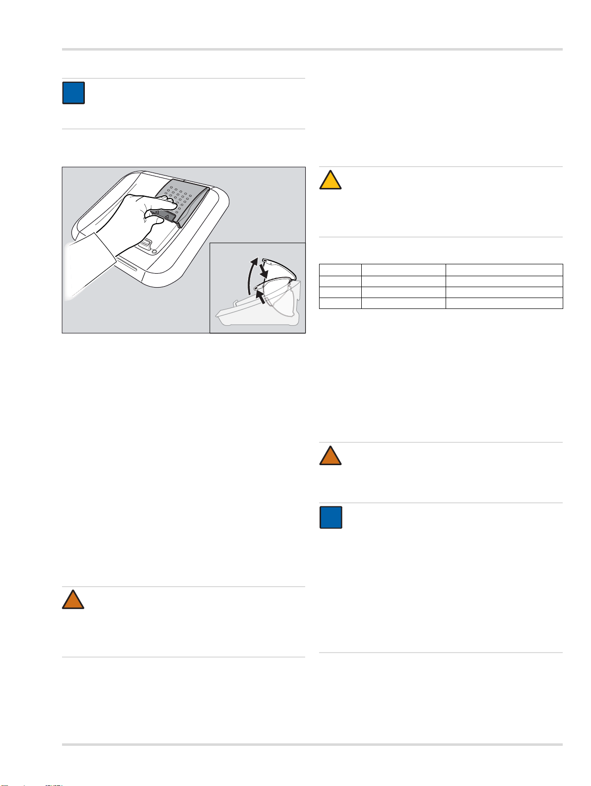
5.2 Inserting or removing the gas measuring device into or from a module
To insert the instrument in the module:
1. If necessary, push the lock up slightly and open the module
cover upwards.
2. Place the instrument in the corresponding module.
3. Close the module cover.
The instrument will be detected automatically.
X-am-125+ module with charging function only:
After the instrument is inserted, the charging status is
displayed for approx. 5 seconds via the charging status
LED.
The charging function starts automatically approx. 15
mintues after the last test.
To remove the instrument from the module:
1. Push the lock up slightly and open the module cover
upwards.
2. Remove the instrument.
5.3 X-am 125+ module with charging function (optional)
WARNING
Risk of explosion! Do not charge underground or in
explosion hazard areas. The X-am 125+ modules with
charging function are constructed in compliance with
regulations for fire-damp weather and explosion
protection.
A new NiMH supply unit reaches its full capacity after 3 full
charge/discharge cycles. Never store the device for
extended periods (max. 2 months) without a power supply
as the internal buffer battery will run down.
If an error occurs:
Remove from the module and re-insert.
If this does not correct the error, have the module repaired.
CAUTION
!
A short-circuit in the charging contacts in the modules,
e. g. due to metal objects falling into the device, will not
damage the station but should be avoided due to a
potential risk of overheating and error displays on the
module.
Overview of charge status LEDs
Colour Status Meaning
green on continuously Charge status 100 %
green flashing Battery charging.
red flashing Charging error
5.4 Station self-test
A self-test is carried out:
When the station is started up.
When the last successful self-test was more than 24 hours
ago and a test is being carried out.
The station is tested for leaks, pump function, and the software
version of the individual modules and the master.
5.5 Conducting a test
WARNING
!
When using methane, propane or butane in the range
>100 %LEL, an exhaust hose (max. 10 m long) must
be connected to the exhaust outlet to ensure the
extraction of excess explosive gas.
NOTICE
i
i
Single mode is activated by default.
Several tests can be started and executed in parallel in
the Single mode.
A failure of a LED, horn or vibration test results in a
negative evaluation of the overall test, and thus in the
locking of the respective gas measurement system.
A testing of the sensor reserve is only performed with
sensors that support this function. The results are
displayed under test details and give information about
the state of the sensor.
It is only possible to charge the instrument batteries using
the X-am 125+ module with charging function.
The charging time is approx. 4 hours for a completely
empty battery.
Dräger X-dock 5300/6300/6600 21
Page 22
Use
X-am 5000
X-dock 5300
0
0
01033286.eps
X-am 5000
X-dock 5300
0
0
01133286.eps
X-am 5000
X-dock 5300
0
0
01133286.eps
The following tests are preconfigured:
Test 1: QT Fast bump test including alarm testing
Test 2: EXT
Test 3: CAL
Extended bump test incl. zero-point check and
alarm testing.
Calibration, alarm test, fresh air flushing and
certificate.
1. If necessary, open the test gas cylinders.
2. If necessary, switch on the X-dock.
3. Perform a visual inspection of the gas measurement
systems (see chapter 5.1 on page 20).
4. Insert the instruments into the modules (see chapter 5.2 on
page 21).
If Single mode is activated:
The preset test is started automatically by closing the
module cover.
The Status LED flashes blue.
The individual test phases are displayed.
If Favorites mode is activated:
Select required test from favourites bar.
The test will be started automatically.
The Status LED flashes blue.
The individual test phases are displayed.
If Test scheduler mode is activated:
If necessary, log user out on the station (see chapter 4.5 on
page 18).
The preset test is performed according to the configured
time schedule.
If required, select the desired instrument field for additional
information.
Remove the instrument from the module.
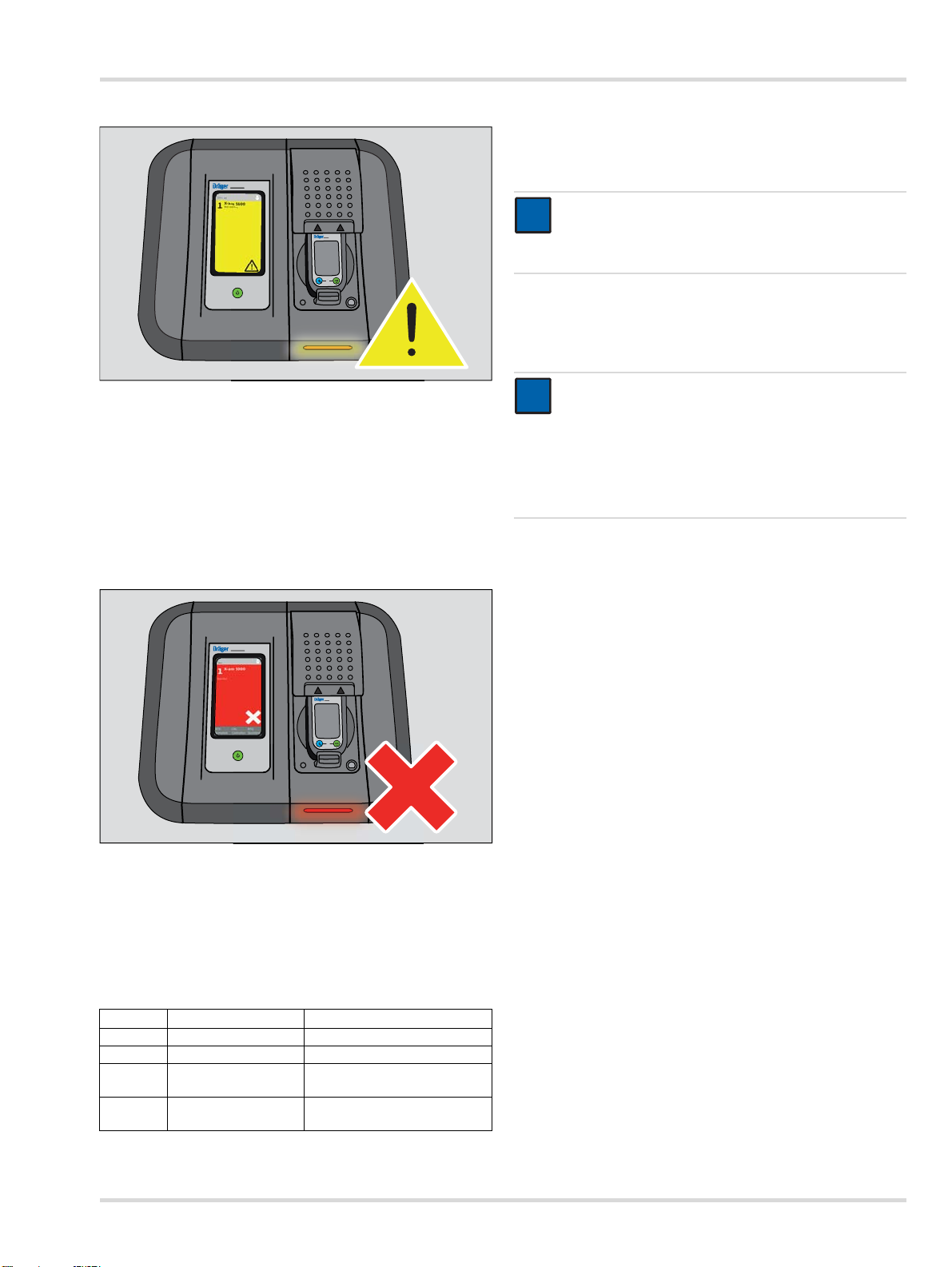
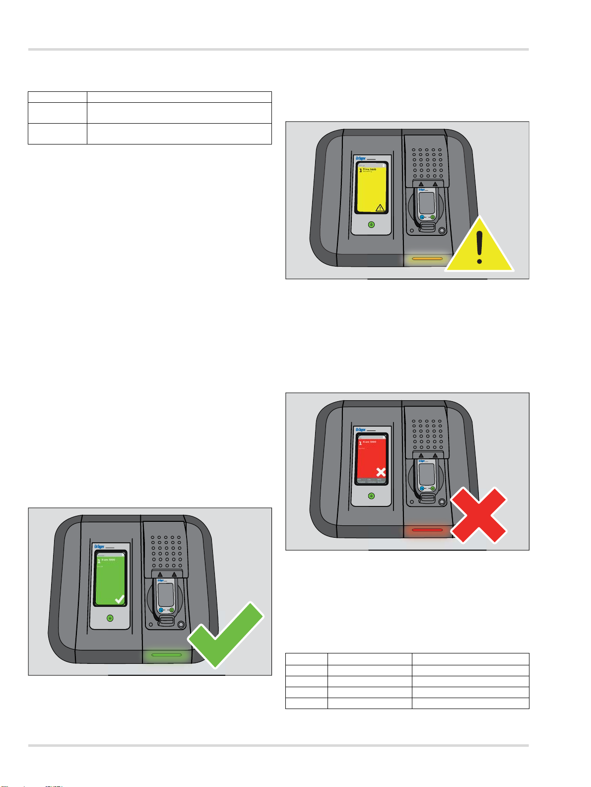
Test passed, with restrictions:
The status means that partial tests of the favourite could not be
performed because of special settings.
Confirmation is shown on the display.
The Status LED flashes yellow.
If required, select the desired instrument field for additional
information.
Remove the instrument from the module.
Test not passed:
If Log-in mode is activated:
Log user in on the station (see chapter 4.5 on page 18).
Select the desired test from favourites bar.
Test will be started automatically.
The status LED flashes blue.
The individual test phases are displayed.
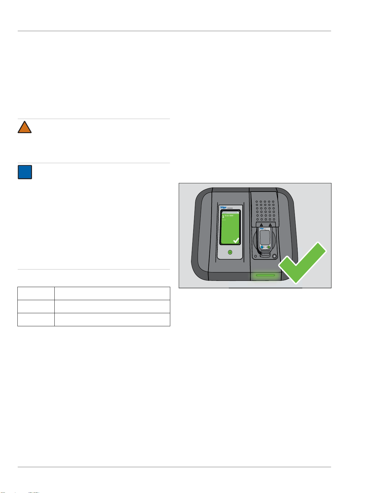
Test passed:
Confirmation is shown on the display.
The Status LED flashes green.
An error message is shown on the display.
The Status LED flashes red.
If required, select the desired instrument field for additional
information.
Identify and rectify the error.
Repeat the test if necessary.
Overview of status LEDs
Colour Status Meaning
blue flashing Process in progress
green flashing Test passed
yellow flashing Test passed, with restrictions
red flashing Test failed/cancelled
22 Dräger X-dock 5300/6300/6600
Page 23
Maintenance
i
i
i
i
!
i
i
5.6 After use
1. If required, remove instruments from modules.
2. Close the test gas cylinders.
NOTICE
To keep energy consumption low, Dräger
recommends switching off the equipment after use
according to the Instructions for Use.
6 Maintenance
6.1 Maintenance intervals
NOTICE
The maintenance intervals must be established in
each individual case and shortened if necessary,
depending on safety considerations, process
conditions, and the technical requirements of the
equipment. Dräger recommend a Dräger service
contract for all maintenance activities and that all
repairs are carried out by Dräger.
6.1.1 Before every start-up
The following work must be carried out before every start-up of
the equipment:
Check the hoses for dirt, brittleness and damage and
replace if necessary.
Check the hoses are secure, to prevent escapes of gas.
Check that all cable connections are secure.
Visual inspection of the modules and sensor seals. If very
dirty or if there are visible defects, the sensor seal must be
replaced.
CAUTION
!
There must not be any older firmware files on the USB
data storage device.
2. Connect the USB data storage device with firmware update
to the USB port on the station.
The USB icon will appear in the status bar.
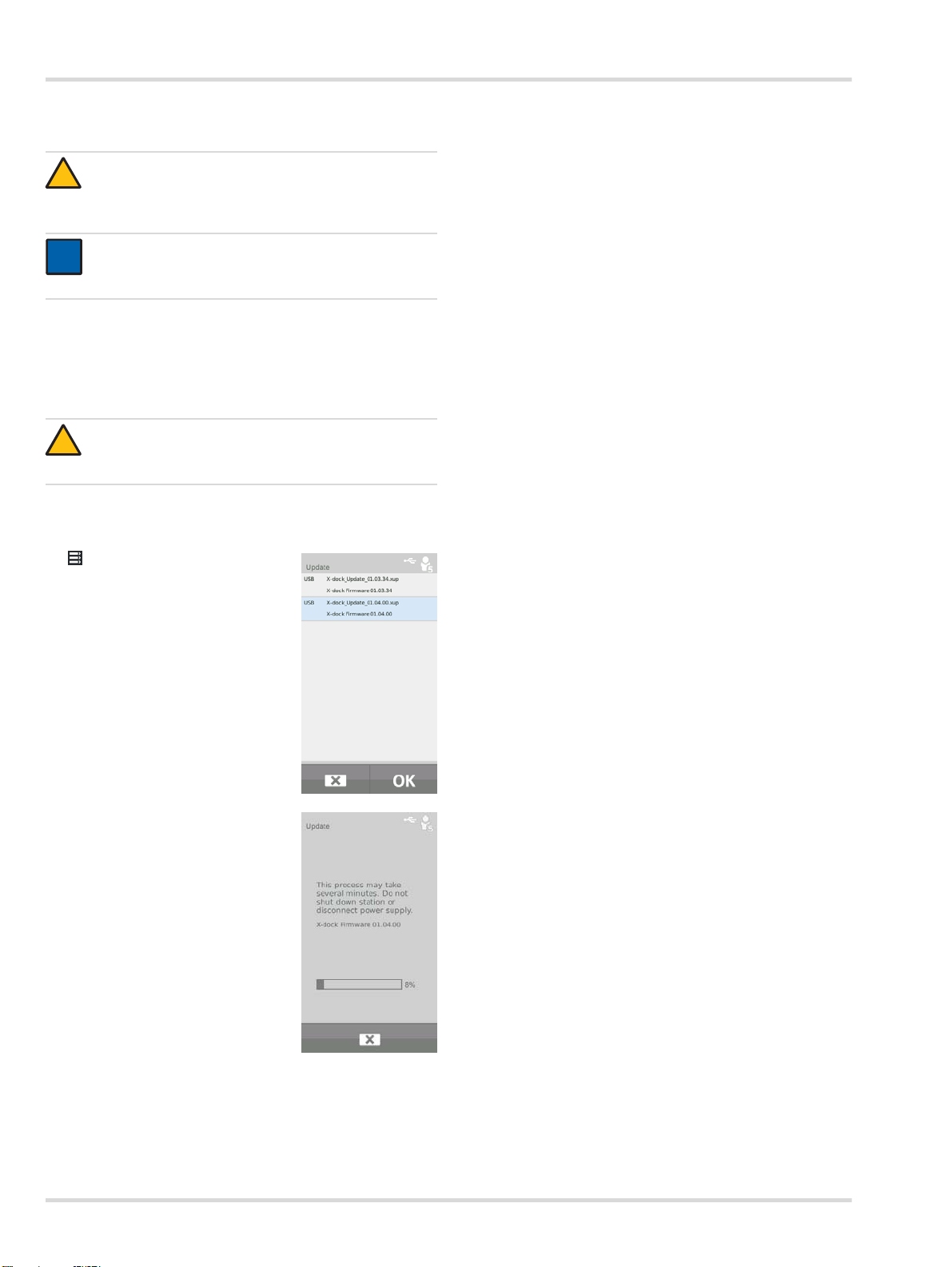
3. Select > System
configuration > Update.
A list of all firmware updates
available on the USB storage
device will be displayed.
4. Select the desired firmware
update from the list. The selected
firmware update is marked in blue.
5. Start the firmware update with OK.
The progress of the installation is
displayed:
6.1.2 Annually
Inspection of the entire X-dock station by competent personnel.
6.2 Perform a firmware update
CAUTION
The station power supply must not be disconnected
during the installation process. The station may be
damaged if this is not observed.
NOTICE
The station does not support any USB data storage
device with an NTFS file system.
1. Download the firmware update from the internet:
a. Go to www.draeger.com.
b. Go to the X-dock product page and unzip the firmware
update to the root directory of an empty USB data
storage device.
6. Following successful transfer to the station, the start is restarted automatically and the firmware update is installed
immediately afterwards. During the installation process,
the status LEDs on the modules will be white.
7. After the installation is complete, the station changes to
operating mode. The station is ready for operation.
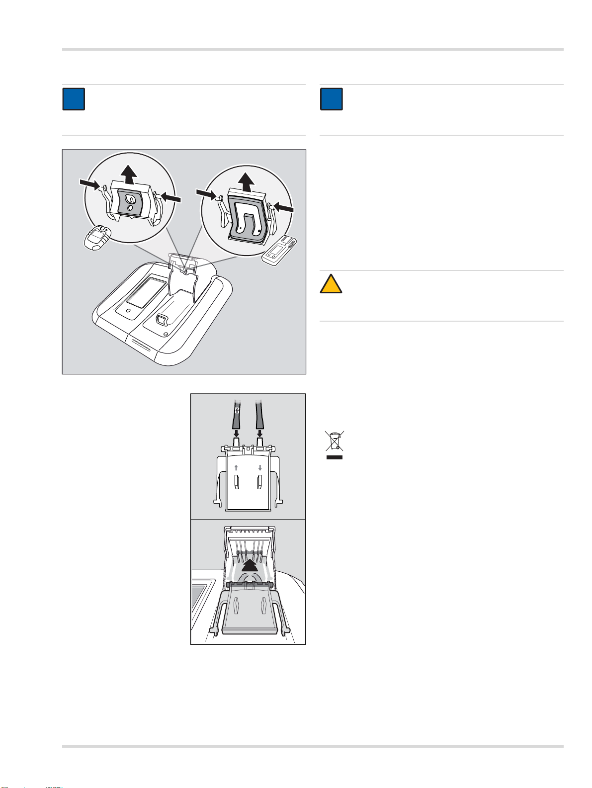
6.3 Changing the sealing insert
NOTICE
i
i
The sealing inserts must be changed at regular
intervals (e. g. at each inspection) or sooner as
required.
Dräger X-dock 5300/6300/6600 23
Page 24
Disposal
00633286.eps
00733286.eps
i
i
1. Open the module cover.
2. Squeeze the two external
locking lugs in and
withdraw the sealing insert
downwards.
3. Release the hoses from
the sealing insert.
4. Replace the sealing insert.
5. Fit the hoses to the new
sealing insert (note the
arrows on the sealing
insert and the hose).
6. Squeeze the external
locking lugs in and insert
the sealing insert into the
module cover until the
locking lugs engage.
7. Check that the sealing
insert is fitted correctly in
the module cover.
6.5 Calibrate touchscreen
1. While starting the system, press and hold the function key
until the calibration display appears.
2. Press the five consecutively displayed position markers as
they appear.
6.6 Cleaning
CAUTION
!
Abrasive cleaning implements (brushes etc.), cleaning
agents and cleaning solvents can destroy the fresh-air
filter.
The device does not need any special care.
If very dirty, the equipment can be carefully wiped down
with a damp cloth.
Carefully dry the device using a cloth.
7 Disposal
Dispose of the product in accordance with the applicable rules
and regulations.
Disposing of electric and electronic equipment:
In accordance with EU Directive 2002/96/EC this
product must not be disposed of as household waste.
This is indicated by the adjacent icon.
You can return this product to Dräger free of charge.
For information please contact the national
marketing organisations and Dräger.
6.4 Changing the fresh air filter
NOTICE
With regular use and depending on the conditions of
use, the fresh air filter should be changed typically
every 2 months.
1. Unscrew the old fresh air filter.
2. Screw in the new fresh air filter.
24 Dräger X-dock 5300/6300/6600
Page 25
8 Technical data 9 Order list
i
i
Technical data
Dimensions (H x W x D):
Master approx. 3.54 x 5.70 x 9.84 inches
(120 x 130 x 250 mm)
Module approx. 3.54 x 5.70 x 9.84 inches
Weight:
Master
Module
Ambient conditions:
During operation
During storage
Gas connections: 1x fresh air connection
X-dock 5300/6300 3x gas inlets
X-dock 6600 6x gas inlets
Inlet pressure:
for the measured gas 0,5 bar ±20 %
for compressed air 0,5 bar ±20 %
Power supply: 11 V - 28 V DC, 6.25 A
Connections: 3x USB 2.0 standard A
Serial no. (year of
manufacture):
CE mark: Electromagnetic compatibility
(90x145x250mm)
approx. 4.02 pounds
(48.23 ounces; 1500 g)
approx. 2.57 pounds
(30.86 ounces; 960 g)
032 °F to +104 °F (0 °C to +40 °C)
-20-4 °F to +122 °F (-20 °C
to +50 °C)
700 to 1300 hPa
max. 95% relative humidity
1x compressed air inlet
1x exhaust outlet
connection, (host, cable <3 m)
1x USB 2.0 mini B connection,
(device, cable <3 m)
1x Ethernet port RJ45
Data transmission rate
10/100 Mbit
The year of construction is given
by the 3rd letter in the factory
number located on the nameplate:
B=2010, C=2011, D=2012,
E=2013, F=2014, G=2015,
H=2016, etc.
Example: Serial number ARFH0054, the 3rd letter is F, so the
year of construction is 2014.
(Directive 2004/108/EC)
Name and description
Dräger X-dock 5300 X-am 125 83 21 880
Dräger X-dock 5300 Pac 83 21 881
Dräger X-dock 6300 Master 83 21 900
Dräger X-dock 6600 Master 83 21 901
Dräger X-dock Module X-am 125 83 21 890
Dräger X-dock Module X-am 125+
(with charging function)
Dräger X-dock Module Pac 83 21 892
Dräger X-dock Module X-am 125,
AA version
Dräger X-dock Module X-am 125+,
AA version (with charging function)
Dräger X-dock Module Pac, AA version 83 24 262
Single wall mount 83 21 922
Comfort wall mount 83 21 910
Cylinder holder (table-top version) 83 21 918
Cylinder holder for top-hat rail 83 21 928
Power pack 24 V / 1.33 A (up to 3
modules)
Power pack 24 V / 6.25 A (up to 10
modules)
X-dock car adapter 83 21 855
Pressure regulator valve 0.5 bar 83 24 250
Pump filter set (includes filter and hose
connector)
Fluoroelastomer hose 12 03 150
Sealing insert (X-am) 83 21 986
Sealing insert (Pac) 83 21 987
X-dock Master display protector film 83 21 804
Stickers for module numbering 83 21 839
Barcode label, exterior
(22 x 8 mm, 500 labels)
Barcode scanner 83 18 792
Dräger X-dock Manager Basic 83 21 860
Dräger X-dock Manager Professional 83 21 870
Dräger X-dock Manager Licence
(1x, both versions)
Dräger X-dock Manager Licence
(5x, both versions)
NOTICE
Dräger recommends the use of Dräger test gas
cylinders.
Order No.
83 21 891
83 24 260
83 24 261
83 21 849
83 21 850
83 19 364
AG02551
83 21 857
83 21 858
Dräger X-dock 5300/6300/6600 25
Page 26

Glossary
10 Glossary
Abbreviation Description
ALARM Alarm element test
BTQ Quick bump test
BTX Extended bump test
CAL Calibration
DB Database
DBMS Database Management System
DL Data logger
FAV Favorite
HORN Horn
LED Light-emitting diode
LEL Lower Explosive Limit
MSD Mass Storage Device
MST Master
SPAN Span calibration
SW Software
T90 Response time test
TWA Time-weighted average
UNDEF Unknown
UNK Unknown info
VIB Vibration
ZCHECK Zero-point check
ZERO Zero-point calibration
26 Dräger X-dock 5300/6300/6600
Page 27
Pour votre sécurité
!
!
i
i
1 Pour votre sécurité
1.1 Consignes générales de sécurité
Veuillez lire attentivement la notice d'utilisation du produit
avant de l'utiliser.
Respecter rigoureusement la notice d'utilisation.
L'utilisateur doit comprendre entièrement les instructions et
les suivre scrupuleusement. Respecter rigoureusement le
domaine d'application indiqué.
Ne pas jeter la notice d'utilisation. Veillez à ce que les
utilisateurs conservent et utilisent ce produit de manière
adéquate.
Seul un personnel suffisamment formé et expérimenté
peut utiliser ce produit.
Respecter les directives locales et nationales relatives à ce
produit.
Seul le personnel compétent et possédant la formation
adéquate est autorisé à contrôler, réparer et entretenir le
produit. Dräger recommande de conclure un contrat de
service qui pourra se charger de tous les travaux de
maintenance.
Le personnel de service suffisamment formé doit contrôler
et maintenir en état le produit selon les indications de ce
document.
Pour les travaux d'entretien, n'utiliser que des pièces et
des accessoires orignaux Dräger. Sans quoi, le
fonctionnement correct du produit pourrait être compromis.
Ne pas utiliser des produits défectueux ou incomplets. Ne
pas effectuer de modifications sur le produit.
Informer Dräger en cas d'erreurs ou de panne du produit
et/ou des pièces du produit.
2 Description
2.1 Aperçu du produit (voir dépliant)
1 Maître
2 Module
3 LED d'état
4 Écran tactile
5 Touche de fonction
6 Entrée d'air frais avec filtre air frais
7 Logement antivol
8 Alimentation électrique
9Ports USB
10 Port Ethernet
11 P o r t m i n i U S B
12 Sortie de gaz
13 Entrées de gaz
14 Entrée d'air comprimé
15 Plaque signalétique
16 Module X-am 125
17 Etat de charge de la LED
18 Module X-am 125+ (avec fonction de charge)
19 Module Pac
2.2 Description du fonctionnement
2.2.1 Maître
Pour la station de maintenance, la station maître gère les tests
de fonctionnement, le calibrage, l'ajustage et les fonctions de
gestion des utilisateurs, de gestion des appareils, d'impression
des comptes-rendus et certificats standard (uniquement avec
imprimantes PostScript) ainsi que l'interface vers l'utilisateur.
1.2 Définition des symboles d'avertissement
Les symboles d'avertissement suivants ont pour fonction de
caractériser et souligner les textes d'avertissement qui
requièrent l'attention accrue de l'utilisateur. Les symboles
d'avertissement sont définis comme suit :
AVERTISSEMENT
Signale une situation potentiellement dangereuse
qui, si elle n'est pas évitée, peut constituer un danger
de mort ou d'accident grave.
ATT ENTION
Signale une situation potentiellement dangereuse qui,
si elle n'est pas évitée, peut constituer des dommages
physiques ou matériels sur le produit ou
l'environnement. Peut également servir
d'avertissement en cas d'utilisation non conforme.
REMARQUE
Informations complémentaires sur l'utilisation du
produit.
2.2.2 Modules
Les modules intègrent les interfaces spécifiques aux
appareils, notamment la communication IR, l'unité de test au
gaz et le contact de charge. Par ailleurs, les modules
comprennent les capteurs de détection des alarmes visuelle,
sonore et vibratoire des appareils.
2.3 Domaine d'application
Dräger X-dock 5300/6300/6600 est une station de
maintenance modulaire. La X-dock permet de réaliser des
calibrages, des ajustages et des tests de gaz automatiques
des détecteurs de gaz portables, simultanément et de manière
indépendante. Un système se compose d'une station maître
pour 3 (X-dock 5300/6300) ou 6 (X-dock 6600) gaz étalon. La
X-dock 5300 comprend une station maître, y compris un
module, et n'est pas extensible. Jusqu'à 10 modules peuvent
être raccordés à la station maître de X-dock 6300 et 6600. Les
modules détectent automatiquement l'insertion d'un appareil
et régulent l'alimentation en gaz afin de garantir à tout moment
l'alimentation adéquate de l'appareil en gaz.
Dräger X-dock 5300/6300/6600 27
Page 28
Installation
i
i
i
i
i
i
i
i
Les détecteurs de gaz suivants peuvent être utilisés avec Xdock et les modules correspondants :
X-dock 5300/6300/6600
avec module Pac : avec module X-am 125 (+) :
Dräger Pac 3500
Dräger Pac 5500
Dräger Pac 7000
Dräger X-am 1700
Dräger X-am 2000
Dräger X-am 2500
Dräger X-am 5000
Dräger X-am 5600
2.4 GPL (General Public License)
Certaines parties du logiciel des appareils utilisent des
logiciels open source publiés sous GPL, LGPL ou une autre
licence Open Source. Il s'agit dans le détail de GPL GPLv2,
LGPL, MIT, PostgreSQL, Apache, Apache 2, zlib. Le texte
source des logiciels utilisés peut être obtenu auprès de Dräger
pendant au moins trois ans à compter de la date d'achat du
produit contenant le logiciel sur CD, en indiquant la référence
83 21 874. Les conditions posées à l'utilisation de la licence
figurent sur le CD du logiciel.
3 Installation
REMARQUE
S'assurer que l'espace de montage est suffisant.
6. Établir l'alimentation en air comprimé ou en air frais :
raccorder le tuyau d'air comprimé au raccord d'air
comprimé (pression de sortie de la vanne de régulation
de la pression 0,5 bar, débit volumétrique >3 l/min).
OU
Au besoin, raccorder le tuyau d'air frais au filtre air frais.
7. Raccorder l'alimentation électrique.
Station comprenant jusqu'à 3 modules : alimentation
électrique 24 V / 1,33 A
Station comprenant de 4 à 10 modules : alimentation
électrique 24 V / 6,25 A
Le système est alimenté électriquement par la station
maître.
REMARQUE
Dräger recommande d'utiliser des bouteilles de gaz
étalon Dräger et des vannes de régulation de la
pression Dräger (voir la liste de commande). Il est
également possible d'utiliser une vanne de régulation
de la pression adéquate avec une pression de sortie
de 0,5 bar et un débit de >3 L/min.
Dräger recommande de raccorder un tuyau
d'échappement de gaz (longueur max. 10 m) à la
sortie du gaz, ce qui permettra d'évacuer le gaz étalon.
La station maître et les modules doivent avoir la même
version de firmware. Dans le cas contraire, effectuer
une mise à jour du firmware (voir la section 6.2 à la
page 34).
1. Au besoin, monter les modules sur la station maître en
suivant les instructions (uniquement pour X-dock 6300/
6600).
10 modules maximum peuvent être installés sur une
station maître.
Les modules disponibles peuvent être combinés selon
besoin.
2. Au besoin, installer le support mural ou de bouteille selon
les instructions.
3. Retirer les raccords d'extrémité sur les entrées et la sortie
de gaz prévues.
REMARQUE
Si le raccord d'extrémité n'est pas retiré de la sortie de
gaz, la station ne pourra pas effectuer proprement
l'auto-test.
4. Brancher les tuyaux d'alimentation en gaz aux entrées de
gaz de la station maître et les relier à la vanne de régulation
de la pression de la bouteille de gaz étalon.
REMARQUE
Dräger recommande de ne pas dépasser une
longueur de 10 m pour les tuyaux d'alimentation en
gaz.
5. Au besoin, raccorder le tuyau d'échappement du gaz
(longueur max. 10 m) à la sortie du gaz.
4 Fonctions de base
4.1 Mise en marche et arrêt de la station
REMARQUE
i
i
En cas d'inactivité pendant 10 minutes, la station
bascule automatiquement en mode Veille.
Pour mettre en marche la station :
Appuyer sur la touche de la station maître pendant
1 seconde.
Les informations suivantes s'affichent pendant la mise en
marche :
Version du logiciel
Pour arrêter la station :
Appuyer sur la touche de la station maître pendant
3 secondes.
La station s'arrête.
Mode Veille :
Le mode Veille est activé s'il n'y a pas d'activité enregistrée
sur la station pendant 10 minutes (entrée sur l'écran tactile
ou ouverture/fermeture d'un volet du module).
Lorsque la station passe en mode Veille, un utilisateur
éventuellement connecté sera déconnecté
automatiquement. Lors du passage au mode
d'exploitation, l'utilisateur doit tout d'abord se reconnecter.
L'écran tactile est désactivé pendant le mode Veille.
Le comportement en charge des modules X-am 125+ avec
fonction de charge n'est pas concerné par le mode Veille.
Les charges sont poursuivies.
28 Dräger X-dock 5300/6300/6600
Page 29
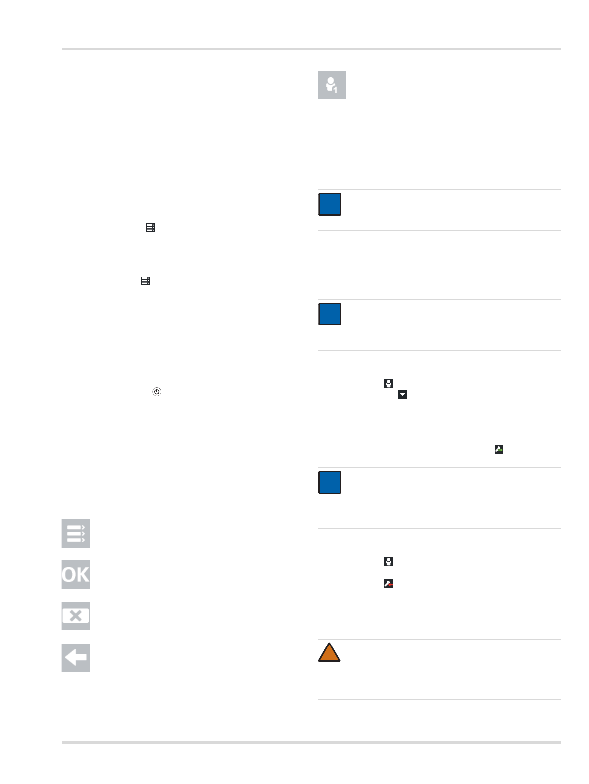
Fonctions de base
i
i
i
i
Pour passer dans le mode d'exploitation :
Actionner brièvement la touche de fonction ou
toucher l'écran tactile ou
ouvrir ou fermer un volet du module.
4.2 Configuration initiale de la station
1. Mettre en marche la station, voir la section 4.1 à la
page 28.
2. Se connecter avec le nom d'utilisateur prédéfini « admin»
(Nom d'utilisateur : admin, mot de passe : 123456), voir la
section 4.5 à la page 29.
3. Configurer l'entrée du gaz étalon, voir la section 4.6 à la
page 29.
4. Modifier évent. la langue :
a. Sélectionner > Configuration du système >
Langue.
b. Sélectionner la langue souhaitée.
c. Confirmer la sélection avec OK.
5. Régler éventuellement l'heure et la date :
a. Sélectionner > Configuration du système > Date &
Heure.
b. Modifier les paramètres souhaités.
c. Confirmer les réglages avec OK.
4.3 Écran tactile
Les touches de l'écran tactile changent dynamiquement en
fonction de la tâche exécutée. Pour exécuter une action,
sélectionner le symbole correspondant sur l'écran.
Appuyer sur la touche de la station maître pour accéder à
l'écran d'accueil.
4.4 Écrans d'accueil et de test
Les touches des écrans d'accueil et de test changent
dynamiquement en fonction de l'état de connexion, du mode
individuel et du nombre de modules utilisés. Pour en savoir
plus, voir le manuel technique X-dock 5300/6300/6600.
4.4.1 Symboles
Menu Appuyer sur ce symbole pour
accéder au menu .
Confirmer Appuyer sur ce symbole pour
confirmer une saisie ou une
fonction.
Annuler Appuyer sur ce symbole pour
annuler une saisie ou une
fonction.
Connexion ou
déconnexion d'un
utilisateur
Appuyer sur ce symbole pour
connecter ou déconnecter un
utilisateur. Le numéro qui
s'affiche dans le symbole
correspond au niveau
d'autorisation (voir la section 6 à
la page 34).
4.5 Connexion ou déconnexion d'un utilisateur
REMARQUE
Utiliser l'ID d'utilisateur pour la connexion.
L'administrateur le crée au préalable.
Un utilisateur possédant les droits d'administrateur est créé
par défaut :
Nom d'utilisateur : admin
Mot de passe : 123456
REMARQUE
Après la première mise en service, Dräger
recommande de modifier le mot de passe « admin »
prédéfini.
Pour connecter un utilisateur :
1. Sélectionner .
a. Sélectionner .
b. Sélectionner le nom d'utilisateur voulu dans la liste.
ou
a. Sélectionner Sélectionner l'utilisateur .
b. Entrer le nom de l'utilisateur voulu.
2. Entrer le mot de passe et confirmer avec .
REMARQUE
i
i
Lors de l'entrée du nom d'utilisateur, 3 suggestions de
recherche correspondant à des noms d'utilisateur
enregistrés s'affichent. Sélectionner le nom
d'utilisateur voulu.
Pour déconnecter l'utilisateur actif :
1. Sélectionner .
Les informations sur l'utilisateur actif s'affichent.
2. Sélectionner .
L'utilisateur actif est déconnecté.
4.6 Configuration de l'entrée du gaz étalon
Retour Appuyer sur ce symbole pour
revenir dans l'écran précédent.
Dräger X-dock 5300/6300/6600 29
AVERTISSEMENT
!
Les concentrations en gaz étalon entrées doivent être
identiques aux informations fournies sur la bouteille de
gaz étalon utilisée. En cas d'erreur, les résultats de la
mesure seront incorrects.
Page 30
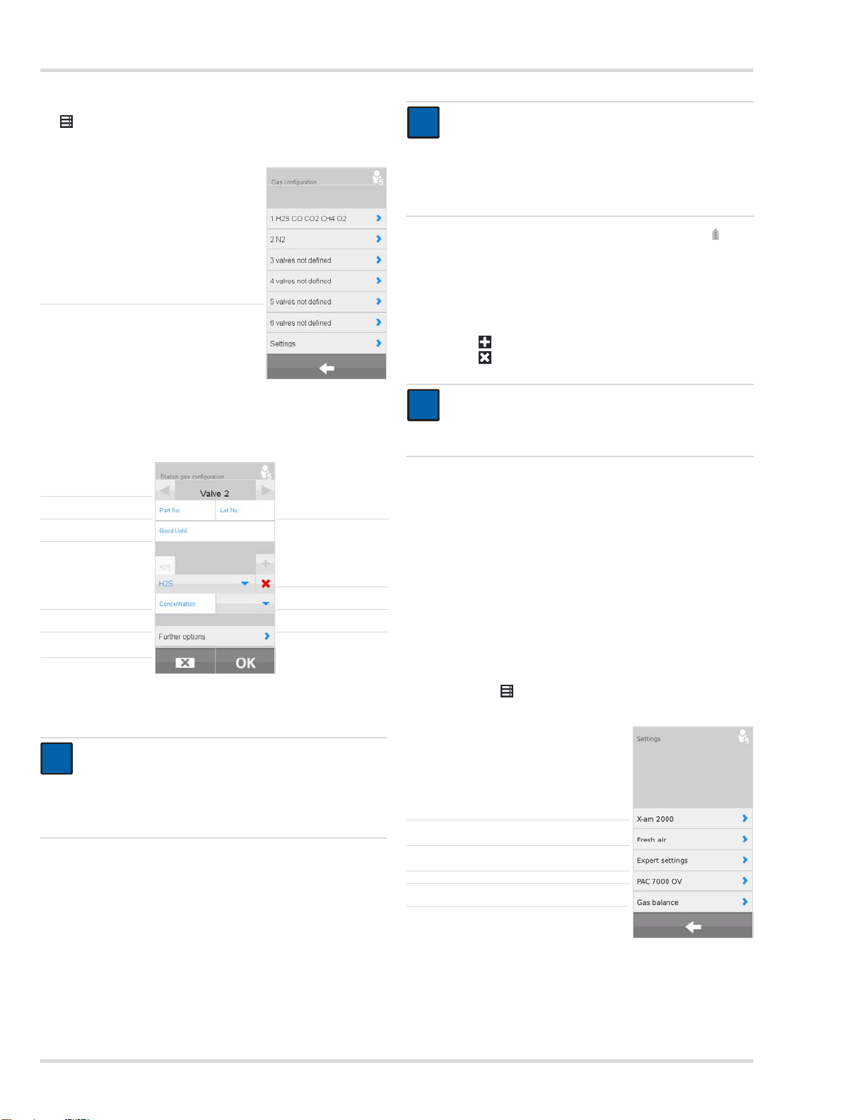
Fonctions de base
i
i
Pour configurer une entrée de gaz étalon :
1. > Sélectionner Config. du gaz (station).
L'aperçu des raccords de gaz étalon s'affiche.
Sélectionner l'entrée de gaz étalon ►
2. Sélectionner l'entrée de gaz étalon souhaitée.
Le menu de configuration s'affiche.
Sélectionner l'entrée
de gaz étalon
Entrer le code article ►◄
Entrer la date
de péremption
Sélectionner
le gaz étalon
Entrer la
concentration
Autres options ►
►
Entrer le numéro de
lot
►
Créer les
◄
composants
►◄Supprimer la
►◄Sélectionner
du gaz étalon
configuration
l'unité
Si une bouteille de gaz étalon Dräger est utilisée :
REMARQUE
i
i
Les valeurs entrées automatiquement doivent être
comparées avec les données figurant sur la bouteille
de gaz étalon. Si les valeurs diffèrent, ce sont celles
figurant sur la bouteille de gaz étalon qui sont valables
et celles entrées automatiquement doivent être
corrigées manuellement.
2. Le cas échéant, sélectionner Autres options et pour
restaurer le contrôle du niveau de remplissage.
3. Au besoin, configurer les autres entrées de gaz étalon de
la même manière.
Si une bouteille de gaz étalon d'un autre fabricant est utilisée :
1. Créer ou supprimer les composants du gaz étalon.
Avec , créer un nouveau composant du gaz étalon.
Avec , supprimer le composant actuel du gaz étalon.
REMARQUE
i
i
La suppression de tous les composants du gaz étalon
efface toutes les informations de l'entrée de gaz
étalon.
2. Sélectionner le gaz étalon.
3. Entrer la concentration du gaz étalon.
4. Sélectionner l'unité du gaz étalon.
5. Au besoin, créer d'autres composants de gaz étalon.
6. Les informations suivantes peuvent être fournies en
option :
Code article de la bouteille de gaz étalon
Numéro de lot de la bouteille de gaz étalon
Date de péremption de la bouteille de gaz étalon
7. Au besoin, indiquer les Autres options.
8. Pour en savoir plus, voir le manuel technique X-dock 5300/
6300/6600.
4.6.1 Paramètres
1. Sélectionner > Config. du gaz (station) > Paramètres.
REMARQUE
Lorsque vous entrez le numéro de référence d'une
bouteille de gaz étalon Dräger, le contrôle du niveau
de remplissage de la bouteille s'affiche
automatiquement dès lors qu'il n'a pas été désactivé
Sélectionner le gaz étalon pour X-am 2000 ►
(voir la section 4.6.1 à la page 30).
Réglage de l'entrée d'air frais ►
1. Entrer le code article de la bouteille de gaz étalon Dräger.
Les informations nécessaires à la configuration sont
enregistrées automatiquement. Elles peuvent être
complétées manuellement par le numéro de lot et la date
Réglages expert ►
Sélectionner le gaz étalon pour Pac 7000 OV ►
Contrôle du niveau de remplissage de la
bouteille
►
de péremption.
Pour le Pac 7000 OV, il est possible pour le capteur OV de
choisir entre deux gaz étalons différents qui peuvent aussi
30 Dräger X-dock 5300/6300/6600
Page 31

Fonctions de base
i
i
servir pour le calibrage et le test. Vous avez le choix entre le
monoxyde de carbone (CO) et l'oxyde d'éthylène (EO).
Trois différents gaz étalons sont proposés pour le X-am 2000.
Ils conviennent également à l'ajustage et au test. Ces gaz sont
le méthane (CH
Suivant le gaz sélectionné, le capteur est ajusté de différente
manière. Pour de plus amples informations à ce sujet,
consulter les fiches techniques des capteurs.
REMARQUE
Le gaz adéquat doit être connecté sur l'une des
entrées de gaz et paramétré au niveau de la
configuration du gaz.
Il est également possible de définir une option de « sensibilité
accrue » pour le propane et le pentane. Cette option augmente
artificiellement la sensibilité pour ajuster les capteurs de
manière à ce qu'ils réagissent approximativement au nonane
(la sensibilité obtenue est comparable à celle qu'ils auraient
s'ils avaient été ajustés avec du nonane). Pour de plus amples
informations sur l'ajustage de la sensibilité croisée, consulter
les fiches techniques des capteurs.
Pour sélectionner le gaz étalon pour X-am 2000 :
1. Sélectionner X-am 2000.
2. Sélectionner le gaz étalon adéquat dans la liste.
Sont proposés :
le méthane - CH
le propane - C
le pentane - PENT
Pour le propane et le pentane, l'option « Sensibilité accrue
» (sensibilité à la vapeur) peut également être activée.
3. Confirmer la sélection avec OK.
), le propane (C3H8) et le pentane (C5H12).
4
(réglage par défaut)
4
3H8
AVERTISSEMENT
!
Seul le personnel spécialisé et ayant suivi une
formation adéquate est autorisé à activer cette
fonction, une concentration incorrecte du gaz étalon
pouvant donner un résultat positif bien que le
détecteur de gaz déclenche trop tard une alarme.
Pour régler le test en cas d'absence de gaz étalon :
1. Sélectionner Gaz absent.
2. Activer la case à cocher (réglage par défaut : activée).
3. Confirmer la sélection avec OK.
Cette fonction permet de déterminer si le test ou un ajustage
doit être réalisé dans le cas où un gaz étalon nécessaire ne
serait pas connecté.
AVERTISSEMENT
!
Si cette fonction est désactivée, le canal
correspondant ne sera pas contrôlé ou ajusté.
Pour sélectionner le gaz étalon pour le Pac 7000 OV :
1. Sélectionner Pac 7000 OV .
2. Sélectionner le gaz étalon adéquat dans la liste.
Sont proposés :
Oxyde d'éthylène - EO (Réglage standard)
Monoxyde de carbone - CO
3. Confirmer la sélection avec OK.
Pour définir le contrôle du niveau de remplissage de la
bouteille :
Pour définir l'entrée d'air frais :
1. Sélectionner Air frais.
2. Sélectionner la pompe (entrée d'air frais ; réglage par
défaut) ou l'entrée d'air comprimé.
3. Confirmer la sélection avec OK.
Les réglages suivants peuvent être réalisés dans la section
Réglages expert :
Ignorer la concentration maximum pour le test au gaz
rapide
Régler les modes de test en cas d'absence de gaz étalon
Pour ignorer la concentration max. admissible recommandée
par Dräger pour le test au gaz rapide :
1. Sélectionner Ignorer conc. max. pr BTQ.
2. Activer la case à cocher (réglage par défaut : désactivée).
3. Confirmer la sélection avec OK.
Si cette fonction est activée, des concentrations de gaz étalon
supérieures à celles recommandées par Dräger peuvent être
utilisées pour le test au gaz rapide.
REMARQUE
i
i
Le contrôle du niveau de remplissage de la bouteille
n'est possible que pour les bouteilles configurées avec
un numéro de référence Dräger.
1. Sélectionner Surv. du niveau.
2. Activer ou désactiver la case de contrôle Surv. du niveau.
3. Confirmer la sélection avec OK.
Pour restaurer le contrôle du niveau de remplissage pour une
nouvelle bouteille de gaz étalon :
1. Raccorder une nouvelle bouteille de gaz étalon au raccord
de gaz étalon.
2. > Sélectionner Config. du gaz (station).
3. Sélectionner l'entrée de gaz étalon souhaitée.
4. Sélectionner Autres options et pour restaurer le
contrôle du niveau de remplissage de la bouteille.
Dräger X-dock 5300/6300/6600 31
Page 32

Utilisation
!
i
i
i
i
00233286.eps
1
2
5 Utilisation
AVERTISSEMENT
Un détendeur défectueux sur la bouteille de gaz étalon
peut accroître la pression dans la station. Les tuyaux
du gaz étalon risquent de se détacher et le gaz étalon
de s'échapper.
Risque pour la santé ! Ne jamais inhaler le gaz étalon.
Respecter les consignes de sécurité des fiches
techniques de sécurité correspondantes. Pour
l'évacuation, mettre à disposition une hotte
d'aspiration ou une sortie vers l'extérieur.
REMARQUE
Pour éviter la fuite de gaz étalon, Dräger recommande
de fermer les bouteilles de gaz étalon lorsque la
station reste sans surveillance pendant une durée
prolongée.
Les erreurs d'appareils et de canaux peuvent
empêcher l'exécution du calibrage.
5.1 Réalisation d'un contrôle visuel
Il est recommandé d'effectuer un contrôle visuel des
détecteurs de gaz avant chaque mise en place dans la station.
1. Vérifier que le boîtier, les filtres extérieurs et les plaques
signalétiques sont en bon état.
2. Contrôler la présence de salissure sur les contacts de
batterie et les entrées du détecteur.
REMARQUE
Les appareils dont le contrôle visuel n'a pas donné les
résultats voulus, ne sont pas posés dans la station.
Dans le cas contraire, l'évaluation globale du test ne
pourra pas être effectuée correctement.
5.2 Installation ou retrait du détecteur de gaz
dans le module
2. Insérer le détecteur de gaz dans le module correspondant.
3. Fermer le volet du module.
Le détecteur de gaz est automatiquement reconnu.
Uniquement pour les modules X-am-125+ avec fonction de
charge :
Après l'insertion du détecteur de gaz, l'état de charge
est affiché pendant env. 5 secondes par la LED d'état
de charge.
La fonction de charge est lancée automatiquement
dans les 15 minutes suivant le dernier test.
Pour retirer le détecteur de gaz du module :
1. Pousser légèrement le verrouillage vers le haut et ouvrir le
volet du module par le haut.
2. Retirer le détecteur de gaz.
5.3 Module X-am 125+ avec fonction de charge
(en option)
AVERTISSEMENT
!
Risque d'explosion ! Ne pas charger l'appareil sous
terre ou dans les environnants à risque d'explosion.
Les modules X-am 125+ avec fonction de charge ne
sont pas construits d'après les directives sur la
protection antidéflagrante et les mélanges grisouteux.
Les accumulateurs des détecteurs de gaz ne peuvent être
chargés qu'avec le module X-am 125+ avec fonction de
charge.
Sur un accumulateur entièrement déchargé, le temps de
charge est d'env. 4 heures.
Un nouveau module d'alimentation NiMH atteint sa
capacité maximum après 3 cycles complets de charge/
décharge. Ne jamais stocker l'appareil pendant une durée
prolongée (max. 2 mois) sans alimentation énergétique,
car la batterie tampon interne se décharge.
En cas de dérangement :
Retirer l'appareil du module et le réinsérer.
Si le dérangement n'est toujours pas éliminé, faire réparer
le module.
ATTE NTION
!
L'apparition d'un court-circuit sur les contacts de
charge des modules, par ex. suite à une chute
d'objets métalliques, n'endommage pas la station.
Néanmoins, ceci devrait être évité en raison des
risques de surchauffe et d'affichage erroné sur le
module.
Sommaire des états de charge de la LED
Couleur Etat Signification
vert affichage continu état de charge 100 %
Pour installer le détecteur de gaz dans le module :
1. Au besoin, pousser légèrement le verrouillage vers le haut
et ouvrir le volet du module par le haut.
32 Dräger X-dock 5300/6300/6600
vert clignotement l'accu est chargé.
rouge clignotement erreur de charge
Page 33

Utilisation
!
i
i
X-am 5000
X-dock 5300
0
0
01033286.eps
X-am 5000
X-dock 5300
0
0
01133286.eps
5.4 Autotest de la station
Un auto-test est réalisé :
Au démarrage de la station.
Si le dernier autotest réussi remonte à plus de 24 heures et
si un test est réalisé.
L'appareil teste l'étanchéité de la station, le fonctionnement de
la pompe, la version logicielle des différents modules et du
maître.
5.5 Exécution du test
AVERTISSEMENT
En cas de test au gaz au méthane, propane ou butane
dans la plage >100 % LIE, raccorder un tuyau
d'échappement de gaz (longueur max. 10 m) à la
sortie de gaz pour assurer l'aspiration de l'excs de gaz
explosible.
REMARQUE
Le mode individuel est activé par défaut.
Plusieurs tests peuvent être démarrés et exécutés
parallèlement en mode individuel.
L'échec d'un test de LED, d'avertissement sonore ou
de vibreur entraîne une évaluation négative du test
complet et verrouille le détecteur de gaz
correspondant.
Si le Mode Plan. test est activé :
Le cas échéant, déconnecter l'utilisateur sur la station (voir
la section 4.5 à la page 29).
Le test préréglé est effectué selon le calendrier configuré.
Si le Mode connex. est activé :
Le cas échéant, connecter l'utilisateur sur la station (voir la
section 4.5 à la page 29).
Sélectionner le test voulu dans la barre des favoris.
Le test démarre automatiquement.
La LED d'état s'allume en bleu.
Chaque phase du test est affichée.
Réussite du test :
On n'effectue de contrôle de la réserve de capteur que
sur les capteurs possédant cette fonction. Le résultat
est affiché dans les détails du test et informe sur l'état
du capteur.
Les tests suivants sont préconfigurés :
Tes t 1 : QUI
Tes t 2 : EXT
Tes t 3 : CAL
Test au gaz rapide, y compris contrôle
d'alarme.
Test au gaz avancé avec contrôle du point zéro
et contrôle d'alarme.
Ajustage, test d'alarme, purge d'air frais et
certificat.
1. Au besoin, ouvrir les bouteilles de gaz étalon.
2. Au besoin, activer la X-dock.
3. Effectuer un contrôle visuel des détecteurs de gaz (voir la
section 5.1 à la page 32).
4. Installer les détecteurs de gaz dans les modules (voir la
section 5.2 à la page 32).
Si le Mode individuel est activé :
Le test prédéfini démarre automatiquement en fermant le
volet de module.
La LED d'état clignote en bleu.
Les phases du test s'affichent.
Si le Mode favoris est activé :
Sélectionner le test souhaité dans la barre des favoris.
Le test démarre automatiquement.
La LED d'état clignote en bleu.
Les phases du test s'affichent.
Une confirmation s'affiche à l'écran.
La LED d'état clignote en vert.
Au besoin, sélectionner la zone de l'appareil pour obtenir
de plus amples informations.
Retirer le détecteur de gaz du module.
Réussite du test, avec des restrictions :
L'état signifie que des tests partiels du favori n'ont pas pu être
réalisés en raison de réglages spéciaux.
Une confirmation s'affiche à l'écran.
La LED d'état clignote en jaune.
Dräger X-dock 5300/6300/6600 33
Page 34

Maintenance
X-am 5000
X-dock 5300
0
0
01133286.eps
i
i
!
Au besoin, sélectionner la zone de l'appareil pour obtenir
de plus amples informations.
Retirer le détecteur de gaz du module.
Échec du test :
Un message d'erreur s'affiche à l'écran.
La LED d'état clignote en rouge.
Au besoin, sélectionner la zone de l'appareil pour obtenir
de plus amples informations.
Identifier et résoudre l'erreur.
Au besoin, répéter le test.
Sommaire de la LED d'état
Couleur Etat Signification
bleu clignotement
vert clignotement Test réussi
jaune clignotement
rouge clignotement Test non réussi/annulé
Processus en cours de
réalisation
Test réussi, avec des
restrictions
5.6 Après l'utilisation
1. Au besoin, retirer les détecteurs de gaz des modules.
2. Fermer les bouteilles de gaz étalon.
6 Maintenance
6.1 Intervalles de maintenance
REMARQUE
i
i
La durée des intervalles d'entretien est à déterminer
au cas par cas et éventuellement à adapter en fonction
des considérations techniques en matière de sécurité,
des conditions techniques du procédé et des
contraintes techniques des appareils. Il est
recommandé de contacter le Dräger Service pour
souscrire à un contrat d'entretien et effectuer les
réparations.
6.1.1 Avant la mise en service
Exécuter les opérations suivantes avant de mettre en service
l'appareil :
Vérifier si les tuyaux sont encrassés, effrités ou
endommagés, les remplacer le cas échéant.
Vérifier la fixation des tuyaux pour éviter la fuite de gaz.
Vérifier la fixation de tous les câbles.
Effectuer un contrôle visuel des modules et des joints des
capteurs. En cas de fort encrassement ou de dommages
visibles, remplacer les joints de capteur.
6.1.2 1 fois/an
Confier le contrôle de l'ensemble de la station X-dock au
personnel qualifié.
6.2 Effectuer une mise à jour du firmware
ATTE NTION
Pendant l'installation, l'alimentation électrique de la
station ne doit pas être coupée. Dans le cas contraire,
la station risque d'être endommagée.
REMARQUE
i
i
La station n'est pas compatible avec les clés USB au
format NFTS.
REMARQUE
Pour réduire la consommation d'énergie, Dräger
recommande d'arrêter l'appareil après utilisation
conformément au manuel.
34 Dräger X-dock 5300/6300/6600
1. Télécharger la mise à jour du firmware sur Internet :
a. Faire www.draeger.com.
b. Appeler la page du produit X-dock et décompacter la
mise à jour du firmware sur une clé USB vide, dans le
répertoire racine.
ATTE NTION
!
La clé USB ne doit pas contenir de fichiers firmware
antérieurs.
2. Connecter la clé USB avec la mise à jour du firmware dans
la prise USB de la station.
Le symbole USB apparaît dans la barre d'état.
Page 35

Maintenance
00733286.eps
3. Sélectionner > Configuration
du système > Mise à jour.
Le système affiche une liste de
toutes les mises à jour du firmware
disponibles sur la clé USB.
4. Sélectionner la mise à jour du
micrologiciel voulue. La mise à
jour du micrologiciel sélectionné
est marquée en bleu.
5. Démarrer la mise à jour du
firmware avec OK. La progression
de l'installation apparaît à l'écran.
6.3 Remplacement des joints d'étanchéité
REMARQUE
i
i
Les joints d'étanchéité doivent être régulièrement
remplacés (par ex. à chaque contrôle) ou plus tôt
selon les besoins.
6. Après la transmission des données sur la station, celle-ci
est redémarrée automatiquement, suivi de l'installation des
mises à jour du firmware. Pendant l'installation, les LED
d'état des modules affichent un signal blanc.
7. Après l'installation, la station passe au mode d'exploitation.
La station est prête.
00633286.eps
1. Ouvrir le volet du module.
2. Presser les deux nez de
verrouillage extérieurs
vers l'intérieur et retirer les
joints d'étanchéité par le
bas.
3. Dégager les tuyaux des
joints d'étanchéité.
4. Remplacer les joints
d'étanchéité.
5. Insérer les tuyaux dans les
supports pour joints
d'étanchéité (observer les
flèches présentes sur
l'élément d'étanchéité et le
tuyau).
6. Presser les deux nez de
verrouillage extérieurs
vers l'intérieur et insérer
les joints d'étanchéité dans
le volet du module jusqu'à
ce que les nez de
verrouillage s'enclenchent.
7. Vérifier si les joints
d'étanchéité sont
correctement fixé dans le
volet du module.
Dräger X-dock 5300/6300/6600 35
Page 36

Elimination
i
i
!
6.4 Remplacement du filtre air frais
REMARQUE
Tous les 2 mois, remplacer le filtre air frais s'il est
utilisé régulièrement et selon les conditions
d'utilisation.
1. Dévisser l'ancien filtre air frais.
2. Visser le nouveau filtre air frais.
6.5 Calibrer l'écran tactile
1. Au démarrage de l'installation, maintenir la touche de
fonction enfoncée jusqu'à ce que l'écran de calibrage
apparaisse.
2. Presser alors les 5 repères de position affichés
successivement.
6.6 Nettoyage
ATTE NTION
Les outils de nettoyage rugueux (brosses, etc.), les
nettoyants et les solvants peuvent détruire le filtre air
frais.
L'appareil ne requiert pas d'entretien particulier.
En cas d'encrassement important, essuyer l'appareil avec
un chiffon humide.
Sécher l'appareil avec un chiffon.
8 Caractéristiques techniques
Dimensions (H x L x P) :
Maître env. 120 x 130 x 250 mm
Module env. 90 x 145 x 250 mm
Poids :
Maître env. 1 500 g
Module env. 960 g
Conditions ambiantes :
En service
En stockage
Raccords de gaz : 1x raccord d'air frais
X-dock 5300/6300 3x entrées de gaz
X-dock 6600 6x entrées de gaz
Pression d'entrée :
pour gaz de mesure 0,5 bar ±20 %
pour l'air comprimé 0,5 bar ±20 %
0°C à +40°C
-20°C à+50°C
700 à 1 300 hPa
Humidité relative max. 95 %
1x entrée d'air comprimé
1x sortie de gaz
7 Elimination
Eliminer le produit en respectant les prescriptions en vigueur.
Elimination des produits électriques et
électroniques :
Conformément à la directive 2002/96/CEE, il est
interdit d'éliminer ce produit avec les déchets
ménagers. C'est pourquoi, il est caractérisé par le
symbole suivant.
Dräger reprend gratuitement ce produit. Pour de plus
amples informations, veuillez consulter les filiales
locales et Dräger.
Alimentation électrique : 11 V - 28 V tension continue,
Connexions : 3x connexion type A standard
N° de série (année de
fabrication) :
Marquage CE : Compatibilité électromagnétique
6,25 A
USB 2.0 (hôte, câble de <3 m)
1x connexion Mini-B, USB 2.0,
(appareil, câble de <3 m)
1x port Ethernet RJ45
Taux de transfert des données
10/100 mbits
L'année de fabrication est
indiquée par la 3e lettre du numéro
de série qui figure sur la plaque
signalétique : B=2010, C=2011,
D=2012, E=2013, F=2014,
G=2015, H=2016, etc.
Exemple : numéro de série ARFH0054, la 3e lettre est un F, l'année
de fabrication est donc 2014.
(directive 2004/108/CE)
36 Dräger X-dock 5300/6300/6600
Page 37

9 Liste de commande
i
i
Liste de commande
Désignation et description
Dräger X-dock 5300 X-am 125 83 21 880
Dräger X-dock 5300 Pac 83 21 881
Dräger X-dock 6300 Station maître 83 21 900
Dräger X-dock 6600 Station maître 83 21 901
Dräger X-dock Module X-am 125 83 21 890
Dräger X-dock Module X-am 125+
(avec fonction de charge)
Dräger X-dock Module Pac 83 21 892
Dräger X-dock Module X-am 125,
version AA
Dräger X-dock Module X-am 125+,
version AA (avec fonction de charge)
Dräger X-dock Module Pac, version AA 83 24 262
Support mural simple 83 21 922
Support mural confort 83 21 910
Support de bouteille (variante sur table) 83 21 918
Support de bouteille pour rail 83 21 928
Alimentation électrique 24 V / 1,33 A
(jusqu'à 3 modules)
Alimentation électrique 24 V / 6,25 A
(jusqu'à 10 modules)
Adaptateur véhicule X-dock 83 21 855
Vanne de régulation de la pression 0,5 bar
Kit de filtres à pompe (comprend un filtre
et un embout de connexion de tuyau)
Tuyaux flexible en fluorélastomère 12 03 150
Joint d'étanchéité (X-am) 83 21 986
Joint d'étanchéité (Pac) 83 21 987
Film de protection d'écran X-dock Master 83 21 804
Autocollant, numérotation du module 83 21 839
N° de référence
83 21 891
83 24 260
83 24 261
83 21 849
83 21 850
83 24 250
83 19 364
Étiquette de code-barres extérieure
(22 x 8 mm, 500 pc.)
Lecteur de code-barres 83 18 792
Logiciel Dräger X-dock Manager Basic 83 21 860
Logiciel Dräger X-dock Manager
Professional
Licence logiciel Dräger X-dock Manager
(1x, deux versions)
Licence logiciel Dräger X-dock Manager
(5x, deux versions)
REMARQUE
Dräger recommande d'utiliser des bouteilles de gaz
étalon Dräger.
Dräger X-dock 5300/6300/6600 37
AG02551
83 21 870
83 21 857
83 21 858
Page 38

Glossaire
10 Glossaire
Abréviation Explication
ALARME Test de l'élément d'alarme
BTQ Test au gaz rapide
BTX Test au gaz avancé
CAL Ajustage
BD Base de données
DBMS Système de gestion de base de données
DL Enregistreur de données
FAV Favori
HORN Avertissement sonore
LED Diode électroluminescente
LIE Limite inférieure d'explosivité
UMS Mémoire de masse
MST Maître
SPAN Ajustage de la sensibilité
SW Logiciel
T90 Test du temps de réponse
TWA Moyenne pondérée dans le temps
UNDEF Inconnu
UNK Entrée inconnue
VIB Vibration
ZCHECK Ctrl pnt zéro
ZERO Ajustage du point zéro
38 Dräger X-dock 5300/6300/6600
Page 39

Para su seguridad
!
!
i
i
1 Para su seguridad
1.1 Indicaciones generales de seguridad
Antes de utilizar el producto, leer atentamente las
instrucciones de uso.
Observar estrictamente las instrucciones de uso. El
usuario debe comprender íntegramente y cumplir
estrictamente las instrucciones. El producto debe utilizarse
exclusivamente según su uso previsto.
No eliminar las instrucciones de uso. Garantizar su
conservación y su uso correcto por parte de los usuarios.
Solo personal especializado y con la formación pertinente
debe utilizar este producto.
Observar las directrices locales y nacionales aplicables a
este producto.
Solo personal especializado y debidamente formado debe
comprobar, reparar y mantener el producto. Dräger
recomienda un contrato de mantenimiento con Dräger y
que todos los trabajos de reparación se realicen por
Dräger.
El personal de mantenimiento debidamente formado debe
comprobar y mantener el producto según las instrucciones
incluidas en este documento.
Utilizar únicamente piezas y accesorios originales de
Dräger para los trabajos de mantenimiento. De lo
contrario, el funcionamiento correcto del producto podría
verse mermado.
No utilizar productos incompletos ni defectuosos. No
realizar modificaciones en el producto.
Informar a Dräger en caso de errores o fallos del producto
o componentes del mismo.
1.2 Significado de las señales de advertencia
Las siguientes señales de advertencia se utilizan en este
documento para identificar y resaltar los textos de advertencia
que requieren mayor atención por parte del usuario. El
significado de las señales de advertencia se define a
continuación:
ADVERTENCIA
Advertencia de una situación potencialmente
peligrosa.
En caso de no evitarse, pueden producirse lesiones
graves e incluso letales.
ATE NCIÓN
Advertencia de una situación potencialmente
peligrosa. En caso de no evitarse, pueden producirse
lesiones o daños en el producto o en el medio
ambiente. Puede utilizarse también para advertir
acerca de un uso incorrecto.
NOTA
Información adicional sobre el uso del producto.
2 Descripción
2.1 Vista general del producto (véase desplegable)
1Master
2 Módulo
3 LED de estado
4 Pantalla táctil
5 Tecla de función
6 Entrada de aire fresco con filtro
7 Ranura de protección contra robo
8 Alimentación eléctrica
9 Conexiones USB
10 Conexión Ethernet
11 Conexión mini-USB
12 Salida de gas
13 Entradas de gas
14 Entrada de aire comprimido
15 Placa de características
16 Módulo X-am 125
17 LED de estado de carga
18 Módulo X-am-125+ (con función de carga)
19 Módulo Pac
2.2 Descripción del funcionamiento
2.2.1 Master
La estación maestra se encarga, para la estación de
mantenimiento, del control del desarrollo de la comprobación
de funciones, la calibración y el ajuste, así como de funciones
para la gestin de usuarios y de aparatos, la impresión de
informes y de certificados estándar (sólo con impresoras
PostScript), actuando también de interfaz con el usuario.
2.2.2 Módulos
En los módulos están integradas las interfaces específicas del
aparato como, p. ej., la comunicación IR, la unidad de
exposición al gas y el contacto de carga. De forma adicional,
los módulos contienen los sensores para la detección de la
alarma óptica y acústica y de la alarma vibratoria de los
aparatos.
Dräger X-dock 5300/6300/6600 39
Page 40

Instalación
i
i
2.3 Uso previsto
La Dräger X-dock 5300/6300/6600 es una estación de
mantenimiento con estructura modular. Con la estación Xdock pueden realizarse calibraciones, ajustes y pruebas de
exposición al gas automatizados de aparatos de medición de
gases portátiles, de forma paralela e independiente entre sí.
Un sistema está compuesto por una estación maestra para 3
gases de prueba (X-dock 5300/6300) o 6 gases de prueba (Xdock 6600). La X-dock 5300 abarca una estación maestra
incluido un módulo y no puede ampliarse. En la estación
maestra de la X-dock 6300 y 6600 pueden conectarse hasta
10 mdulos. Los módulos detectan automáticamente la
inserción de un aparato y regulan la alimentación de gas, de
forma que quede garantizado en todo momento el suministro
de gas correspondiente al aparato.
Es posible utilizar los siguientes equipos de medición de gas
con la X-dock y los módulos correspondientes:
X-dock 5300/6300/6600
con módulo Pac: con módulo X-am 125 (+):
Dräger Pac 3500
Dräger Pac 5500
Dräger Pac 7000
Dräger X-am 1700
Dräger X-am 2000
Dräger X-am 2500
Dräger X-am 5000
Dräger X-am 5600
2.4 GPL (Licencia pública general)
Algunas partes del software del equipo utilizan software de
código abierto publicado bajo GPL, LGPL u otra licencia de
código abierto. Se trata, en concreto, de GPL GPLv2, LGPL,
MIT, PostgreSQL, Apache, Apache 2 y zlib. Durante un
período de al menos tres años tras la compra del producto que
contiene el software es posible adquirir en CD y a través de
Dräger los textos fuente del software utilizado indicando el
número de referencia 83 21 874. Las disposiciones
pertinentes de la licencia del software mencionado se
adjuntan en un CD.
3 Instalación
NOTA
i
i
Si no se quita la boquilla de la salida de gas, la estación
no podrá ejecutar el auto chequeo correctamente.
4. Acoplar los tubos flexibles de alimentación de gas a las
entradas de gas de la estación maestra y conectarlos a la
válvula reguladora de presión de la botella de gas de prueba.
NOTA
i
i
Dräger recomienda no superar una longitud de tubo
flexible de 10 m para los tubos flexibles de
alimentación de gas.
5. Dado el caso, conectar el tubo flexible de gas de escape
(máx. 10 m de longitud) a la salida de gas.
6. Asegurar la alimentación de aire comprimido o de aire fresco:
Conectar el tubo flexible a la conexión de aire
comprimido (presión de salida de la válvula reguladora
de presión de 0,5 bar, caudal >3 L/min).
O
Conectar el tubo flexible al filtro de aire fresco.
7. Conectar la fuente de alimentación.
Estación con hasta 3 módulos: fuente de alimentación
de 24 V / 1,33 A
Estación con 4 a 10 módulos: fuente de alimentación
de 24 V / 6,25 A
El sistema completo se alimenta a través de la estación
maestra.
NOTA
i
i
Dräger recomienda utilizar botellas de gas de prueba
Dräger y válvulas reguladoras de presión Dräger (véase
la lista de referencias). De forma alternativa existe la
posibilidad de utilizar una válvula reguladora de presión
adecuada con una presión de salida de 0,5 bar y un
caudal de >3 L/min.
NOTA
Comprobar que se disponga de espacio suficiente
para la estructura completa.
La estación maestra y todos los módulos deben tener
la misma versión de firmware. Si este no fuera el caso,
se deberá llevar a cabo una actualización de firmware
(véase el capítulo 6.2 en la página 47).
1. Dado el caso, montar en la estación maestra los módulos
según las instrucciones de montaje correspondientes (solo
con X-dock 6300/6600).
Es posible montar un máximo de 10 módulos en una
estación maestra.
Los módulos disponibles pueden combinarse según se
desee.
2. Si fuera necesario, montar el soporte de pared o de botella
conforme a las instrucciones de montaje correspondientes.
3. Retirar las boquillas de las entradas de gas previstas y de
la salida de gas.
40 Dräger X-dock 5300/6300/6600
Dräger recomienda conectar un tubo flexible de gas de
escape (máx. 10 m de longitud) a la salida de gas con el
fin de conducir al exterior a través del mismo el gas de
prueba.
Page 41

Fundamentos
i
i
4 Fundamentos
4.1 Conectar y desconectar la estación
NOTA
Si no se produce ninguna acción durante 10 minutos,
la estación cambia automáticamente al modo de
reposo (standby).
Para conectar la estación:
Pulsar la tecla de la estación maestra durante aprox.
1 segundo.
Durante el proceso de conexión se muestra la siguiente
información:
Número de versión de software
Para desconectar la estación:
Pulsar la tecla de la estación maestra durante aprox.
3 segundos.
La estación se desconecta.
Modo de reposo (standby):
El modo de reposo se activa una vez transcurridos aprox.
10 minutos sin que se realice ninguna actividad en la
estación (entrada de datos a través de la pantalla táctil o
apertura/cierre de una tapa de módulo).
Cuando la estación cambia al modo de reposo, finaliza
automáticamente la sesión de los usuarios que pudieran
estar registrados. Al cambiar al modo operativo, el usuario
deberá registrarse de nuevo.
La pantalla táctil se desconecta durante el modo de
reposo.
El comportamiento de carga de los módulos X-am 125+
con función de carga no se ve afectado por el modo de
reposo. Las cargas se siguen llevando a cabo.
Para cambiar al modo operativo:
Accionar brevemente la tecla de función o
tocar la pantalla táctil o
abrir o cerrar una tapa de módulo.
4.2 Primera configuración de la estación
1. Conectar la estación, véase el capítulo 4.1 en la página 41.
2. Registrarse con el usuario preconfigurado "admin"
(nombre de usuario: admin, contraseña: 123456), véase el
capítulo 4.5 en la página 41.
3. Configurar la entrada de gas de prueba, véase el
capítulo 4.6 en la página 42.
4. Dado el caso, cambiar de idioma:
a. Seleccionar > Configuración de sistema > Idioma.
b. Seleccionar el idioma deseado.
c. Confirmar la selección con OK.
5. Dado el caso, ajustar la fecha y la hora:
a. Seleccionar > Configuración de sistema > Fecha;
hora.
b. Realizar los ajustes deseados.
c. Confirmar los ajustes con OK.
4.3 Pantalla táctil
Los botones de la pantalla táctil cambian de forma dinámica,
en función de la tarea que se está realizando. Para llevar a
cabo una acción, seleccionar el símbolo correspondiente en la
pantalla.
Es posible pulsar en todo momento la tecla de la estación
maestra para regresar a la pantalla de inicio.
4.4 Pantallas de inicio y de prueba
Los botones de las pantallas de inicio y de prueba cambian de
forma dinámica, en función del estado de registro y del modo
individual y del número de módulos utilizados. Para obtener
más información, véase el manual técnico de la X-dock 5300/
6300/6600.
4.4.1 Símbolos
Menú Seleccionar este botón para
Confirmar Seleccionar este botón para
Cancelar Seleccionar este botón para
Atrás Seleccionar este botón para
Iniciar o finalizar
sesión de usuario
acceder al menú.
confirmar una entrada o una
función.
cancelar una entrada o una
función.
regresar a la pantalla anterior.
Seleccionar este botón para
iniciar o finalizar la sesión de
usuario. El número en el
símbolo indica el nivel de
autorización correspondiente
(véase el capítulo 6 en la
página 46).
4.5 Iniciar o finalizar sesión de usuario
NOTA
i
i
Para iniciar una sesión se necesita una ID de usuario.
El administrador debe crearlo previamente.
El aparato se suministra con un usuario con derechos de
administración configurado:
Nombre de usuario: admin
Contraseña: 123456
Dräger X-dock 5300/6300/6600 41
Page 42

Fundamentos
i
i
i
i
!
NOTA
Dräger recomienda cambiar la contraseña del usuario
preconfigurado "admin" después de la primera puesta
en marcha.
Para iniciar la sesión de usuario:
1. Seleccionar .
a. Seleccionar .
b. Seleccionar el nombre de usuario deseado de la lista.
o
a. Seleccionar Seleccionar usuario.
b. Introducir el nombre de usuario deseado.
2. Introducir la contraseña y confirmar con .
NOTA
Al introducir el nombre de usuario se mostrarán de
manera automática 3 sugerencias de búsqueda de
nombres de usuario almacenados. Para una selección
rápida, elija el nombre de usuario deseado.
Para finalizar la sesión de usuario:
1. Seleccionar .
Se muestra información sobre el usuario actual.
2. Seleccionar .
Finaliza la sesión del usuario actual.
4.6 Configurar la entrada de gas de prueba
ADVERTENCIA
Las concentraciones de gas de prueba introducidas
deben ser idénticas a los datos indicados en la botella
de gas de prueba utilizada. En caso de datos
incorrectos pueden obtenerse resultados de medición
erróneos.
Para configurar una entrada de gas de prueba:
1. Seleccionar > Config. gas prueba de estación.
Se muestra una relación de las conexiones de gas de
prueba.
2. Seleccionar la entrada de gas de prueba deseada.
Se abre el menú de configuración.
Seleccionar la
entrada de gas de
prueba
Introducir el n.º de
referencia
Introducir la fecha de
caducidad
Seleccionar
el gas de prueba
Introducir la
concentración
Otras opciones ►
En caso de utilizar una botella de gas de prueba Dräger:
NOTA
i
i
Al introducir un número de referencia de una botella de
gas de prueba Dräger, se mostrará automáticamente
el control del nivel de llenado de la botella siempre y
cuando este no haya sido desactivado (véase el
capítulo 4.6.1 en la página 43).
1. Introducir el número de referencia de la botella de gas de
prueba Dräger.
Todos los datos necesarios para la configuración se
cumplimentan automáticamente. El número de lote y la
fecha de caducidad se pueden introducir adicionalmente a
mano.
NOTA
i
i
Los valores introducidos de forma automática deberán
ser comparados con los datos de la botella de gas de
prueba. Si los valores no difieren, los datos válidos
serán los de la botella de gas, y los valores se deberán
corregir de forma manual.
2. En caso necesario, seleccionar Otras opciones y para
restablecer el control del nivel de llenado de la botella.
3. Dado el caso, configurar de igual forma más entradas de
gas de prueba.
►
►◄
►
►◄Borrar la
►◄Seleccionar
Introducir el n.º de
lote
Crear el componente
◄
de gas de prueba
configuración
la unidad
En caso de utilizar una botella de gas de prueba de otro
fabricante:
1. Crear o eliminar el componente de gas de prueba.
Crear con un nuevo componente de gas de prueba.
Eliminar con el componente de gas de prueba
actual.
Seleccionar la entrada de gas de prueba ►
42 Dräger X-dock 5300/6300/6600
NOTA
i
i
Al eliminar todos los componentes de gas de prueba
se eliminan todos los datos de la entrada de gas de
prueba.
Page 43

Fundamentos
i
i
2. Seleccionar el gas de prueba.
3. Introducir la concentración de gas de prueba.
4. Seleccionar la unidad del gas de prueba.
5. Dado el caso, crear más componentes de gas de prueba.
6. La siguiente información puede introducirse
opcionalmente:
Número de referencia de la botella de gas de prueba
Número de lote de la botella de gas de prueba
Fecha de caducidad de la botella de gas de prueba
7. Dado el caso, introducir Otras opciones.
8. Para obtener más información, véase el manual técnico de
la X-dock 5300/6300/6600.
4.6.1 Ajustes
1. Seleccionar > Config. gas prueba de estación >
Ajustes.
Seleccionar el gas de prueba para X-am 2000 ►
Ajuste de la entrada de aire fresco ►
Ajustes avanzados ►
Seleccionar el gas de prueba para Pac 7000 OV
Control del nivel de llenado de la botella ►
►
1. Seleccionar X-am 2000.
2. Seleccionar el gas de prueba deseado de la lista.
Puede seleccionarse:
Metano - CH
Propano - C
Pentano - PENT
(ajuste estándar)
4
3H8
En el caso del propano y pentano existe adicionalmente la
posibilidad de activar la opción "Sensibilidad aumentada"
(sensibilidad al vapor).
3. Confirmar la selección con OK.
Para ajustar la entrada de aire fresco:
1. Seleccionar
Aire fresco
.
2. Seleccionar la bomba (entrada de aire fresco; ajuste
estándar) o la entrada de aire comprimido.
3. Confirmar la selección con OK.
En Ajustes avanzados pueden efectuarse los siguientes
ajustes:
Ignorar la concentración máxima para prueba de
exposición al gas rápida
Ajustar el procedimiento de prueba en caso de faltar gases
de prueba
Para ignorar la concentración máx. permitida recomendada
por Dräger para la prueba de exposición al gas rápida:
1. Seleccionar Ignorar conc. máx. para BTQ.
2. Activar la casilla de selección (ajuste estándar:
desactivada).
3. Confirmar la selección con OK.
Para el Pac 7000 OV se puede elegir entre 2 gases de prueba
diferentes para el sensor OV que también se usan para el
ajuste y la prueba. Se puede elegir entre monóxido de carbono
(CO) y óxido de etileno (EO).
Para el X-am 2000 se puede elegir entre 3 gases de prueba
diferentes, que también se utilizan para el ajuste y la prueba.
Puede seleccionarse metano (CH
pentano (C5H12). En función del gas seleccionado, la
), propano (C3H8) y
4
sensibilidad del sensor se ajusta de forma diferente. Puede
encontrarse más información al respecto en las
correspondientes hojas de datos del sensor.
NOTA
El gas correspondiente debe estar conectado a una de
las entradas de gas y ajustado en la configuración de
gas.
En el caso del propano y del pentano existe adicionalmente la
posibilidad de activar una opción para "Sensibilidad
aumentada". A través de esta opción se incrementa
artificialmente la sensibilidad para ajustar los sensores, de
modo que estos posean aproximadamente una sensibilidad al
nonano (es decir, una sensibilidad propia de un ajuste para
nonano). Puede encontrarse más información sobre el tema
de la sensibilidad transversal en las correspondientes hojas de
datos del sensor.
Si se activa esta función, pueden utilizarse para la prueba de
exposición al gas rápida concentraciones de gas de prueba
superiores a las recomendadas por Dräger.
ADVERTENCIA
!
Esta función debe activarse exclusivamente por
personal especializado formado ya que una
concentración de gas de prueba seleccionada
incorrectamente puede conducir a un resultado de
prueba positivo, a pesar de que el aparato de medición
de gas active las alarmas demasiado tarde.
Para ajustar el procedimiento de prueba en caso de faltar
gases de prueba:
1. Seleccionar Falta de gas.
2. Activar la casilla de selección (ajuste estándar: activada).
3. Confirmar la selección con OK.
Con esta función puede ajustarse si debe realizarse una
prueba o ajuste incluso si no está conectado un gas de prueba
necesario.
ADVERTENCIA
!
Si se desactiva esta función, el canal correspondiente
no se comprueba o ajusta.
Para seleccionar el gas de prueba para X-am 2000:
Dräger X-dock 5300/6300/6600 43
Page 44

Uso
i
i
!
i
i
00233286.eps
1
2
Para seleccionar el gas de prueba para el Pac 7000 OV:
1. Seleccionar Pac 7000 OV .
2. Seleccionar el gas de prueba deseado de la lista.
Puede seleccionarse:
Óxido de etileno - EO (ajuste estándar)
Monóxido de carbono - CO
3. Confirmar la selección con OK.
Para ajustar el control del nivel de llenado de la botella:
NOTA
El control del nivel de llenado de la botella está
disponible únicamente para botellas configuradas con
un número de referencia Dräger.
1. Seleccionar Ctrl nivel llenado.
2. Activar o desactivar la casilla de control Ctrl nivel llenado.
3. Confirmar la selección con OK.
Para restablecer el control del nivel de llenado de la botella
para una botella de gas de prueba nueva:
1. Conectar la botella de gas de prueba nueva a la conexión
de gas de prueba.
2. > Seleccionar Config. gas prueba de estación.
3. Seleccionar la entrada de gas de prueba deseada.
4. Seleccionar Otras opciones y para restablecer el
control del nivel de llenado de la botella encendido.
5Uso
ADVERTENCIA
Un reductor de presión defectuoso en la botella de gas
de prueba puede originar un incremento de la presión
en la estación. Esto puede hacer que los tubos
flexibles del gas de prueba se suelten, provocando un
escape de gas de prueba.
¡Peligro para la salud! No inhalar el gas de prueba.
Consultar las advertencias de peligro de las hojas de
datos de seguridad correspondientes. Garantizar una
derivación a una salida o hacia el exterior.
NOTA
Para evitar las pérdidas de gas de prueba, Dräger
recomienda cerrar las botellas de gas de prueba
cuando la estación permanezca sin supervisión
durante un período prolongado.
NOTA
i
i
Los aparatos que no hayan superado la inspección
visual no deben insertarse en la estación. En caso
contrario no será posible efectuar correctamente la
valoración total de la prueba.
5.2 Insertar o extraer el aparato de medición de gas del módulo
Para insertar el aparato de medición de gas en el módulo:
1. Dado el caso, presionar levemente hacia arriba el bloqueo
y abrir la tapa del módulo hacia arriba.
2. Insertar el aparato de medición de gas en el módulo
correspondiente.
3. Cerrar la tapa del módulo.
El aparato de medición de gas se detecta
automáticamente.
Solo con módulos X-am-125+ con función de carga:
Una vez insertado el aparato de medición de gas se
muestra el estado de carga durante aprox. 5 segundos
mediante el LED de estado de carga.
La función de carga comienza automáticamente unos
15 minutos después de la última prueba.
Para extraer el aparato de medición de gas del módulo:
1. Presionar levemente hacia arriba el bloqueo y abrir la tapa
del módulo hacia arriba.
2. Extraer el aparato de medición de gas.
Los fallos del equipo o del canal pueden hacer que no
sea posible realizar un ajuste.
5.1 Realizar una inspección visual
Realizar una inspección visual de los aparatos de medición de
gas cada vez que se vayan a utilizar en la estación.
1. Comprobar la integridad de la carcasa, el filtro exterior y la
placa de características.
2. Comprobar si hay suciedad en los contactos de la batería
y en las entradas de los sensores.
44 Dräger X-dock 5300/6300/6600
5.3 Módulo X-am-125+ con función de carga (opcional)
ADVERTENCIA
!
¡Riesgo de explosión! No cargar en subterráneos ni en
zonas potencialmente explosivas. Los módulos X-am
125+ con función de carga no han sido fabricados
conforme a las directrices relativas al grisú y la
protección contra explosiones.
Page 45

Uso
!
Solo es posible cargar las baterías de los aparatos de
medición de gas con el módulo X-am 125+ con función de
carga.
Si la batería está completamente descargada, el tiempo de
carga de la misma es de unas 4 horas.
Una unidad de alimentación NiMH nueva alcanza su
capacidad plena tras 3 ciclos completos de carga y
descarga. No almacenar el aparato durante mucho tiempo
(máx. 2 meses) sin suministro de energa, ya que se agota
la batería de respaldo interna.
En caso de fallo:
Extraer el aparato del módulo y volver a insertarlo.
Si el fallo persiste, encargar la reparación del módulo.
ATE NCIÓN
Un cortocircuito de los contactos de carga en los
módulos, p. ej. si caen dentro objetos metálicos, no
provoca daños en la estación, aunque debería
evitarse por el potencial riesgo de calentamiento y la
indicación de anomalías en el módulo.
Descripción general del LED de estado de carga
Color Estado Significado
verde
verde parpadeante La batería se está cargando.
rojo parpadeante Fallo de carga
encendido
permanentemente
estado de carga 100 %
5.4 Auto chequeo de la estación
Se lleva a cabo un auto chequeo de la estación:
Al poner en marcha la estación.
Si el último auto chequeo correcto se llevó a cabo hace
más de 24 horas y se está realizando una prueba.
Se comprueba la estanqueidad de la estación, el
funcionamiento de la bomba, la versión de software de los
diferentes módulos y la estación maestra.
5.5 Realizar la prueba
ADVERTENCIA
!
En el caso de aplicar gas metano, propano o butano dentro
de un rango >100 %L.I.E., debe haberse conectado un
tubo flexible de gas de escape (máx. 10 m de longitud) a
la salida de gas para garantizar la salida de un posible
exceso de gas con riesgo de explosión.
NOTA
i
i
El aparato se suministra con el modo individual activado.
Es posible iniciar y realizar varias pruebas en paralelo en
el modo individual.
Un fracaso en una de las pruebas de los LED, de las
bocinas o de la vibración produciría una evaluación
negativa de la prueba general y, con ello, un bloqueo
del aparato de medición de gas correspondiente.
La comprobación de la reserva de sensores solo se
realizará en sensores compatibles con esta función. El
resultado se muestra en los detalles de la prueba y
proporciona información sobre el estado del sensor.
Están preconfiguradas las siguientes pruebas:
Prueba 1: QUI
Prueba 2: EXT
Prueba 3: CAL
1. Dado el caso, abrir las botellas de gas de prueba.
2. Conectar la X-dock.
Realizar una inspección visual de los aparatos de medición
3.
de gas
4. Introducir los aparatos de medición de gas en los módulos
(véase el capítulo 5.2 en la página 44).
Si el Modo indiv. está activado:
La prueba preajustada se inicia automáticamente cerrando la
tapa del módulo.
El LED de estado parpadea de color azul.
Se muestra cada una de las fases de la prueba.
Prueba de exposición al gas rápida incluida
comprobación de alarma.
Prueba de exposición al gas ampliada incluida
comprobación del punto cero y de alarma.
Ajuste, prueba de alarma, barrido de aire fresco y
certificado.
(véase el capítulo 5.1 en la página 44).
Si el Modo favoritos está activado:
Seleccionar la prueba deseada en la barra de favoritos.
La prueba se inicia automáticamente.
El LED de estado parpadea de color azul.
Se muestra cada una de las fases de la prueba.
Si el modo Planificador de prueba está activado:
En caso necesario, cerrar la sesión del usuario en la
estación (véase el capítulo 4.5 en la página 41).
La prueba preconfigurada se realiza según el horario
configurado.
Dräger X-dock 5300/6300/6600 45
Page 46

Mantenimiento
X-am 5000
X-dock 5300
0
0
01033286.eps
X-am 5000
X-dock 5300
0
0
01133286.eps
X-am 5000
X-dock 5300
0
0
01133286.eps
Si el Modo de registro está activado:
Iniciar sesión de usuario en la estación (véase el
capítulo 4.5 en la página 41).
Seleccionar las pruebas deseadas de la barra de favoritos.
La prueba se inicia automáticamente.
El LED de estado parpadea en azul.
Se muestra cada una de las fases de la prueba.
Prueba superada:
En la pantalla se muestra una confirmación.
El LED de estado parpadea en color verde.
Dado el caso, seleccionar el campo deseado del aparato
para obtener más información.
Extraer el aparato de medición de gas del módulo.
Prueba superada, con limitaciones:
Prueba no superada:
En la pantalla se muestra un mensaje de error.
El LED de estado parpadea en color rojo.
Dado el caso, seleccionar el campo deseado del aparato
para obtener más información.
Identificar y subsanar el error.
Si fuera necesario, repetir la prueba.
Descripción general del LED de estado
Color Estado Significado
azul parpadeante Proceso en curso
verde parpadeante
amarillo parpadeante
rojo parpadeante
Prueba superada
correctamente
Prueba superada, con
limitaciones
Prueba no superada/
cancelada
El estado significa que no han podido llevarse a cabo pruebas
parciales del favorito debido a ajustes especiales.
En la pantalla se muestra una confirmación.
El LED de estado parpadea en color amarillo.
Dado el caso, seleccionar el campo deseado del aparato
para obtener más información.
Extraer el aparato de medición de gas del módulo.
5.6 Después del uso
1. Extraer los aparatos de medición de gas de los módulos.
2. Cerrar las botellas de gas de prueba.
NOTA
i
i
Para mantener el consumo energético lo más bajo
posible, Dräger recomienda desconectar el aparato
después del uso según las instrucciones.
6 Mantenimiento
6.1 Intervalos de mantenimiento
NOTA
i
i
Determinar los intervalos de mantenimiento según las
indicaciones propias de seguridad, las
particularidades técnicas del proceso y los requisitos
técnicos del aparato y, en caso necesario, reducirlos.
Dräger recomienda el Servicio Técnico Dräger para
cerrar un contrato de servicio de asistencia técnica,
así como para las reparaciones.
46 Dräger X-dock 5300/6300/6600
Page 47

Mantenimiento
!
i
i
!
i
i
6.1.1 Antes de cada puesta en marcha
Realizar los siguientes trabajos antes de cada puesta en
marcha del aparato:
Comprobar si los tubos flexibles presentan suciedad,
fragilidad y daños y, dado el caso, sustituirlos.
Comprobar el acople correcto de los tubos flexibles para
evitar el escape de gas.
Comprobar el acople correcto de las conexiones de todos
los cables.
Realizar un control visual de los módulos y de las juntas de
los sensores. En caso de suciedad intensa o de defectos
visibles, sustituir las juntas de los sensores.
6.1.2 Anualmente
Inspección de la estación X-dock completa por parte de
personal especializado cada 12 meses.
6.2 Realizar la actualización del firmware
ATE NCIÓN
Durante el proceso de instalación no se debe
desconectar la estación del suministro de tensión. De
hacerlo, la estación podría resultar dañada.
NOTA
La estación no es compatible con ninguna memoria de
datos USB con sistema de archivos NTFS.
1. Descargar la actualización del firmware de la red:
a. Abrir www.draeger.com.
b. Abrir la página de productos de X-dock y descomprimir
la actualización del firmware en el directorio de raíz
(root) de una memoria de datos USB vacía.
5. Iniciar la actualización del
firmware OK. Se muestra el
progreso de la instalación.
6. Una vez finalizada correctamente la transferencia a la
estación, se lleva a cabo automáticamente un reinicio de la
misma con la instalación a continuación de la actualización
del firmware. Durante el proceso de instalación se
encienden de color blanco los LED de estado de los
módulos.
7. Tras finalizar la instalación correctamente, la estación
cambia al modo operativo. La estación está operativa.
6.3 Sustituir las juntas
NOTA
Las juntas deben sustituirse en intervalos regulares
(p. ej., en cada inspección anual) o antes si fuera
necesario.
ATE NCIÓN
¡En la memoria de datos USB no debe haber ningún
archivo de firmware más antiguo!
2. Conectar la memoria de datos USB con la actualización
del firmware a la conexión USB de la estación.
El símbolo USB aparece en la barra de estado.
3. Seleccionar > Configuración
de sistema > Actualización.
Se muestra una lista con todas las
actualizaciones de firmware
disponibles en la memoria de
datos USB.
4. Seleccionar de la lista la
actualizacón de firmware
deseada. La actualización de
firmware seleccionada se marca
en azul.
00633286.eps
Dräger X-dock 5300/6300/6600 47
Page 48

Eliminación
00733286.eps
i
i
!
1. Abrir la tapa del módulo.
2. Presionar hacia dentro las
dos lengüetas de bloqueo
exteriores y extraer la junta
hacia abajo.
3. Soltar los tubos flexibles
de la junta.
4. Sustituir la junta.
5. Acoplar los tubos flexibles
a la nueva junta (observar
las flechas de la junta y del
tubo flexible).
6. Presionar hacia dentro las
lengüetas de bloqueo
exteriores e introducir la
junta en la tapa del módulo
hasta que las lengüetas de
bloqueo queden
encajadas.
7. Comprobar que la junta
esté asentada
correctamente en la tapa
del módulo.
6.4 Sustituir el filtro de aire fresco
NOTA
En caso de uso regular y en función de las condiciones
de uso, el filtro de aire fresco debe sustituirse,
generalmente, cada 2 meses.
7 Eliminación
Eliminar el producto según las normativas en vigor.
Eliminación de equipos eléctricos y electrónicos:
Según la directiva 2002/96/CE, este producto no
debe eliminarse como residuo doméstico. Por este
motivo está identificado con el símbolo contiguo.
Dräger recoge el producto de forma totalmente
gratuita. La información a este respecto está
disponible en las delegaciones nacionales y en
Dräger.
1. Desenroscar el filtro de aire fresco usado.
2. Enroscar el filtro de aire fresco nuevo.
6.5 Calibrar la pantalla táctil
1. Al arrancar la instalación, mantener pulsada la tecla de
función hasta que se muestre la indicación de calibración.
2. Pulsar en las 5 marcas de posicionamiento indicadas
consecutivamente.
6.6 Limpieza
ATEN CIÓN
Los objetos de limpieza ásperos (cepillos, etc.),
detergentes y disolventes pueden dañar el filtro de aire
fresco.
El aparato no necesita cuidados especiales.
En caso de suciedad intensa, el aparato puede limpiarse
con cuidado utilizando un paño húmedo.
Secar el aparato con un paño.
48 Dräger X-dock 5300/6300/6600
Page 49

8 Características técnicas 9 Lista de referencias
i
i
Características técnicas
Dimensiones (Al x An x F):
Estación maestra (Master) Aprox. 120 x 130 x 250 mm
Módulo Aprox. 90 x 145 x 250 mm
Peso:
Estación maestra (Master) Aprox. 1.500 g
Módulo Aprox. 960 g
Condiciones ambientales:
Durante el funcionamiento
Durante el almacenamiento
Conexiones de gas: 1 conexión de aire fresco
X-dock 5300/6300 3 entradas de gas
X-dock 6600 6 entradas de gas
Presión de entrada:
Para gas de medición 0,5 bar ±20 %
Para aire comprimido 0,5 bar ±20 %
Alimentación eléctrica: 11 V - 28 V de tensión continua,
Conexiones: 3 conexiones A estándar USB
N.º de serie (año de
fabricación):
Marcado CE: Compatibilidad electromagnética
0°C a +40°C
-20°C a+50°C
De 700 a 1.300 hPa
Máx. 95% de humedad relativa
1 entrada de aire comprimido
1 salida de gas
6,25 A
2.0, (host, cable <3 m)
1 conexión Mini B USB 2.0
(dispositivo, cable <3 m)
1 conexión Ethernet RJ45
Velocidad de transferencia de
datos
10/100 Mbit
El año de fabricación se indica
con la 3ª letra del número de
serie que aparece en la placa de
características: B=2010,
C=2011, D=2012, E=2013,
F=2014, G=2015, H=2016, etc.
Ejemplo: Número de serie
ARFH-0054, la 3ª letra es la F, es
decir, el año de fabricación es
2014.
(directiva 2004/108/CE)
Denominación y descripción
Dräger X-dock 5300 X-am 125 83 21 880
Dräger X-dock 5300 Pac 83 21 881
Dräger X-dock 6300 Master 83 21 900
Dräger X-dock 6600 Master 83 21 901
Módulo Dräger X-dock X-am 125 83 21 890
Módulo Dräger X-dock X-am 125+
(con función de carga)
Módulo Dräger X-dock Pac 83 21 892
Módulo Dräger X-dock X-am 125, versión AA 83 24 260
Módulo Dräger X-dock X-am 125+,
versiónAA (con función de carga)
Módulo Dräger X-dock Pac, versión AA 83 24 262
Soporte de pared simple 83 21 922
Soporte de pared confort 83 21 910
Soporte de botella (variante para mesa) 83 21 918
Soporte de botella con perfil curvado 83 21 928
Fuente de alimentación de 24 V / 1,33 A (hasta 3
módulos)
Fuente de alimentación de 24 V / 6,25 A (hasta
10 módulos)
Adaptador para vehículo X-dock 83 21 855
Válvula reguladora de presión de 0,5 bar 83 24 250
Juego de filtros de bomba (compuesto por filtros
y una boquilla de conexión para tubo flexible)
Tubo flexible de caucho fluorado 12 03 150
Junta (X-am) 83 21 986
Junta (Pac) 83 21 987
Protector de pantalla para X-dock maestra 83 21 804
Etiqueta adhesiva para numeración de módulos 83 21 839
Etiquetas de código de barras exteriores
(22 x 8 mm, 500 und.)
Escáner de código de barras 83 18 792
Dräger X-dock Manager Basic 83 21 860
Dräger X-dock Manager Professional 83 21 870
Licencia de Dräger X-dock Manager
(1, ambas versiones)
Licencia de Dräger X-dock Manager
(5, ambas versiones)
Referencia
83 21 891
83 24 261
83 21 849
83 21 850
83 19 364
AG02551
83 21 857
83 21 858
NOTA
Dräger recomienda utilizar botellas de gas de prueba
Dräger.
Dräger X-dock 5300/6300/6600 49
Page 50

Glosario
10 Glosario
Abreviatura Explicación
ALARM Prueba de los elementos de alarma
BTQ Prueba exposición gas rápida
BTX Prueba exposición gas avanzada
CAL Ajuste
DB Base de datos
DBMS Sistema de gestión de base de datos
DL Registrador de datos
FAV Favorito
HORN Bocina
LED Diodo luminoso
LEL Límite de exposición inferior
MSD Dispositivo de almacenamiento masivo
MST Estación maestra (Master)
SPAN Ajuste de sensibilidad
SW Software
T90 Prueba de tiempo de respuesta
TWA Valor medio de turno
UNDEF Desconocido
UNK Dato desconocido
VIB Vibración
ZCHECK Comprobación punto cero
ZERO Ajuste del punto cero
50 Dräger X-dock 5300/6300/6600
Page 51

Para sua segurança
!
!
i
i
1 Para sua segurança
1.1 Instruções gerais de segurança
Antes da utilização do produto, leia atentamente as
instruções de utilização.
Respeite as instruções de utilização. A utilização deste
equipamento exige o perfeito conhecimento e o rigoroso
cumprimento destas instruções de utilização. O produto
destina-se apenas finalidade descrita.
Não deite fora as instruções de utilização. Garanta a
conservação e a utilização correcta por parte dos
utilizadores.
Este produto só pode ser utilizado por pessoal formado e
devidamente qualificado.
Respeite as directivas locais e nacionais aplicáveis a este
produto.
Os trabalhos de verificação, reparação e manutenção do
produto só podem ser efectuados por pessoal técnico
qualificado. A Dräger recomenda que seja estabelecido
um contrato de assistência técnica com a Dräger e que
todas as manutenções sejam também por eles efectuadas.
O pessoal da assistência técnica suficientemente formado
tem de testar e conservar o produto de acordo com as
instruções do presente documento.
Nos trabalhos de manutenção só devem ser utilizadas
peças originais e acessórios originais Dräger. Caso
contrário, o correcto funcionamento do produto será
prejudicado.
Não utilize produtos com avaria ou incompletos. Não
efectue quaisquer alterações no produto.
Informe a Dräger em caso de avaria ou falha no produto
(componentes do produto).
1.2 Significado dos símbolos de atenção
Os seguintes símbolos são utilizados neste documento para
assinalar e realçar os textos, que requerem maior atenção por
parte do utilizador. Os significados dos símbolos são definidos
do seguinte modo:
ATENÇÃO
Indica uma potencial situação de perigo.
Se esta situação não for evitada, pode resultar em
ferimentos graves ou morte.
CUIDADO
Indica uma potencial situação de perigo. Se esta
situação não for evitada, pode provocar danos físicos,
danos materiais ou danos para o ambiente. Também
pode ser utilizado para alertar para práticas indevidas.
NOTA
Informação adicional sobre a utilização do
equipamento.
2 Descrição
2.1 Panorâmica do produto (consulte o desdobrável)
1Master
2 Módulo
3 LED de estado
4 Ecrã táctil
5 Tecla de função
6 Entrada de ar fresco com filtro de ar fresco
7 Ranhura de protecção anti-roubo
8 Alimentação eléctrica
9 Ligações USB
10 Ligação de Ethernet
11 Ligação USB mini
12 Saída de gás
13 Entradas de gás
14 Entrada de ar comprimido
15 Placa de identificação
16 Módulo X-am 125
17 LED de estado de carga
18 Módulo X-am 125+ (com função de carga)
19 Módulo Pac
2.2 Especificação de funções
2.2.1 Master
O equipamento Master assume o comando de execução da
estação de manutenção para os testes de funcionamento,
calibração, ajuste, bem como das funções para gestão de
utilizadores, para gestão de aparelhos, para impressão de
relatórios padrão e certificados padrão (apenas com
impressão PostScript), bem como o comando da interface
para os utilizadores.
2.2.2 Módulos
Nos módulos estão integradas as interfaces específicas do
aparelho, como por ex., comunicação IV, unidade de absorção
de gás e contacto de carga. Além disso, os módulos têm
também sensores para a detecção do alarme óptico e acústico
e do alarme vibratório dos aparelhos.
2.3 Finalidade
O X-dock 5300/6300/6600 da Dräger é uma estação de
manutenção instalada de forma modular. Com o X-dock
podem realizar-se calibrações, ajustes e testes de absorção
de gás de forma automatizada de aparelhos de medição de
gás portáteis, de forma paralela e independente. O sistema é
composto por um equipamento Master para 3 (X-dock 5300/
6300) ou 6 (X-dock 6600) tipos de gás de ensaio. O X-dock
5300 abrange um Master incluindo um módulo e não é
extensível. No Master da X-dock 6300 e 6600 podem ser
ligados até 10 módulos. Os módulos detectam
automaticamente quando um aparelho foi colocado e regulam
a alimentação do gás, de modo a que, em qualquer altura, seja
garantido o abastecimento correspondente do aparelho.
Os seguintes aparelhos de medição de gás podem ser
utilizados com o X-dock e com os respectivos módulos:
Dräger X-dock 5300/6300/6600 51
Page 52

Instalação
i
i
i
i
i
i
X-dock 5300/6300/6600
com módulo Pac: com módulo X-am 125 (+):
Pac 3500 da Dräger
Pac 5500 da Dräger
Pac 7000 da Dräger
X-am 1700 da Dräger
X-am 2000 da Dräger
X-am 2500 da Dräger
X-am 5000 da Dräger
X-am 5600 da Dräger
2.4 GPL (Licença Pública Geral)
As partes do software do aparelho que foram publicadas ao
abrigo da licença GPL, LGPL ou de outra licença do OpenSource, utilizam o software Open-Source. Em particular, tratase de GPL GPLv2, LGPL, MIT, PostgreSQL, Apache, Apache
2, zlib. Os textos de origem do software utilizado poderão ser
solicitados junto da Dräger até um período de, pelo menos,
três anos após aquisição do produto com o software no CD de
suporte de dados, indicando o número de material 83 21 874.
As respectivas normas da licença do software mencionado
encontram-se no CD.
3 Instalação
NOTA
Verificar se existe espaço suficiente para todos os
módulos.
O Master e todos os módulos têm de possuir a mesma
versão de Firmware. Se não for este o caso, tem de se
efectuar uma actualização do Firmware (veja o
capítulo 6.2 na página 59).
5. Se necessário, ligar a mangueira de gás de escape (máx.
10 m de comprimento)
6. Garantir a alimentação de ar comprimido ou ar fresco:
Ligar a mangueira de ar comprimido à ligação de ar
comprimido (pressão de saída da válvula de regulação
de pressão 0,5 bar, fluxo volumétrico >3 L/min).
OU
Se necessário, ligar a mangueira de ar fresco ao filtro
de ar fresco.
7. Ligar a rede eléctrica.
Estação com até 3 módulos: Rede eléctrica 24 V /
1,33 A
Estação com 4 a 10 módulos: Rede eléctrica 24 V /
6,25 A
Todo o sistema é alimentado com corrente eléctrica
através do Master.
NOTA
i
i
A Dräger recomenda a utilização de garrafas de gás
de ensaio da Dräger e válvulas de regulação de
pressão da Dräger (ver descrição e referência para
encomenda). Como alternativa, é possível utilizar uma
válvula de regulação da pressão com uma saída de
pressão de 0,5 bar e uma corrente volumétrica de
>3 L/min.
A Dräger recomenda ligar uma mangueira de gás de
escape (máx. 10 m de comprimento) à saída de gás
direccionando assim o gás de ensaio para o ar livre.
4 Princípios
1. Se necessário, montar os módulos de acordo com as
respectivas instruções de montagem no Master (apenas
na X-dock 6300/6600).
Podem ser montados até 10 módulos num Master.
Os módulos disponíveis podem ser combinados de
qualquer forma.
2. Se necessário, montar o suporte de parede ou das
garrafas de acordo com as respectivas instruções de
montagem.
3. Retirar as mangas das entradas de gás previstas e da
saída de gás.
NOTA
Se a manga não for retirada da saída de gás, a
estação não consegue realizar o auto-teste na
perfeição.
4. Colocar as mangueiras de alimentação do gás nas
entradas de gás do Master e ligar com a válvula de
regulação de pressão da garrafa de gás de ensaio.
NOTA
A Dräger recomenda que as mangueiras de
alimentação de gás não devem exceder um
comprimento de 10 m.
4.1 Ligar ou desligar a estação
NOTA
i
i
Se não decorrer nenhuma acção durante 10 minutos,
a estação muda automaticamente para o modo
Standby.
Para ligar a estação:
Manter a tecla pressionada no Master durante aprox.
1 segundo.
Durante o processo de ligação, são apresentadas as
seguintes informações:
Número da versão do software
Para desligar a estação:
Manter a tecla pressionada no Master durante aprox.
3 segundos.
A estação desliga-se.
Modo Standby:
O modo Standby é activado após cerca de 10 minutos sem
actividade na estação (introdução através de ecrã táctil ou
da abertura/fecho de uma tampa do módulo).
52 Dräger X-dock 5300/6300/6600
Page 53

Princípios
Quando a estação comutar para o modo Standby, termina
automaticamente a sessão do utilizador registado. Ao
comutar para o modo de funcionamento, o utilizador tem
de efectuar novo registo.
O ecrã táctil é desligado durante o modo Standby.
A operação de carga dos módulos X-am 125+ com função
de carga não é afectada pelo modo Standby. As operações
de carga continuam a ser realizadas.
Para comutar para o modo de funcionamento:
Premir brevemente a tecla de função ou
tocar no ecrã táctil ou
abrir ou fechar uma tampa do módulo.
4.2 Configuração inicial da estação
1. Ligar a estação, veja o capítulo 4.1 na página 52.
2. iniciar sessão com o utilizador pré-configurado "admin"
(Nome de utilizador: admin, palavra-passe: 123456), veja
o capítulo 4.5 na página 53.
3. Configurar a entrada de gás de ensaio, veja o capítulo 4.6
na página 54.
4. Se necessário, alterar o idioma:
a. Seleccionar > System configuration > Language.
b. Seleccionar o idioma pretendido.
c. Confirmar a selecção com OK.
5. Se necessário, acertar a data e a hora:
a. Seleccionar > System configuration > Date &
time.
b. Efectuar os ajustes pretendidos.
c. Confirmar os ajustes com OK.
4.3 Ecrã táctil
Os botões do ecrã táctil alteram-se de forma dinâmica,
dependendo da tarefa já efectuada. Para executar uma acção,
seleccionar o respectivo símbolo no ecrã.
Em qualquer altura pode pressionar-se a tecla no Master,
para aceder ao ecrã inicial.
4.4 Ecrã inicial e ecrã de ensaio
Os botões dos ecrãs inicial e de ensaio alteram-se de forma
dinâmica, dependendo do estado de início de sessão, do
estado do modo individual e do número de módulos utilizados.
Para mais informações, consulte o manual técnico X-dock
5300/6300/6600.
4.4.1 Símbolos
Menu Seleccionar este botão para
aceder ao menu.
Cancelar Seleccionar este botão para
cancelar uma introdução ou
função.
Voltar Seleccionar este botão para
aceder ao ecrã anterior.
Iniciar ou terminar
sessão do utilizador
Seleccionar este botão para
iniciar ou terminar sessão do
utilizador. O número no símbolo
indica o respectivo nível de
autorização (veja o capítulo 6
na página 58).
4.5 Iniciar ou terminar sessão do utilizador
NOTA
i
i
Para iniciar sessão é necessário uma ID de utilizador.
Esta tem de ser criada previamente pelo
administrador.
Por predefinição é criado um utilizador com direitos de
administrador:
Nome de utilizador: admin
Palavra-passe: 123456
NOTA
i
i
A Dräger recomenda alterar a palavra-passe do
utilizador predefinido após a primeira colocação em
funcionamento.
Para iniciar uma sessão de utilizador:
1. Seleccionar .
a. Seleccionar .
b. Seleccionar nome de utilizador pretendido a partir da
lista.
ou
a. Seleccionar Select user .
b. Inserir nome do utilizador pretendido.
2. Introduzir a palavra-passe e confirmar com .
NOTA
i
i
Durante a introdução do nome de utilizador são
apresentados automaticamente 3 sugestões de
nomes de utilizadores guardados. Para uma pesquisa
rápida, seleccionar o nome de utilizador pretendido.
Para terminar a actual sessão do utilizador:
Confirmar Seleccionar este botão para
confirmar uma introdução ou
função.
Dräger X-dock 5300/6300/6600 53
1. Seleccionar .
As informações sobre o utilizador actual são
apresentadas.
2. Seleccionar .
O utilizador actual termina a sessão.
Page 54

Princípios
!
i
i
4.6 Configurar a entrada de gás de ensaio
ATENÇÃO
As concentrações de gás de ensaio registadas têm de
ser idênticas às indicações da garrafa de gás de
ensaio utilizada. Em caso de indicações incorrectas
ocorrem resultados de medição deficientes.
Para configurar uma entrada de gás de ensaio:
1. Seleccionar >Station gas configuration.
A vista geral das ligações de gás de ensaio é apresentada.
Seleccionar entrada de gás de ensaio ►
2. Seleccionar entrada de gás de ensaio pretendida.
Aparece o menu de configuração.
Seleccionar a
entrada do gás de
ensaio
Introduzir nº de
produto
Introduzir data de
validade
Seleccionar o gás de
ensaio
Introduzir
concentração
Outras opções ►
►
►◄Introduzir nº de lote
►
Criar componentes
◄
►◄Eliminar a
►◄Seleccionar a
do gás de ensaio
configuração
unidade
1. Introduzir o número de produto da garrafa de gás de
ensaio da Dräger.
Todas as indicações necessárias para a configuração são
preenchidas automaticamente. O número de lote e a data
de validade podem ser adicionalmente registados à mão.
NOTA
i
i
Os valores inseridos automaticamente têm de
idênticos às indicações da garrafa de gás de ensaio
utilizada. Se os valores não forem idênticos, serão
válidas as indicações na garrafa de gás de ensaio e os
valores devem ser corrigidos manualmente.
2. Se necessário, seleccionar Further options e seleccionar
, para reiniciar o indicador de enchimento da garrafa.
3. Se necessário, configurar as entradas de gás de ensaio da
mesma forma.
Em caso de utilização de uma garrafa de gás de ensaio de
outro fabricante:
1. Criar ou eliminar componentes de gás de ensaio.
Com criar um novo componente de gás de ensaio.
Com eliminar o actual componente de gás de
ensaio.
NOTA
i
i
Ao eliminar todos os componentes de gás de teste,
todas as indicações da entrada de gás de ensaio são
eliminadas.
2. Seleccionar o gás de ensaio.
3. Introduzir a concentração de gás de ensaio.
4. Seleccionar a unidade de gás de ensaio.
5. Se necessário, criar outros componentes de gás de
ensaio.
6. As informações seguintes podem ser indicadas
opcionalmente:
Número de produto da garrafa de gás de ensaio
Número de lote da garrafa de gás de ensaio
Data de validade da garrafa de gás de ensaio
7. Se necessário indicar Further options.
8. Para mais informações, consulte o manual técnico X-dock
5300/6300/6600.
4.6.1 Definições
1. Seleccionar > Station gas configuration > Settings.
Em caso de utilização de uma garrafa de gás de ensaio da
Dräger:
NOTA
Ao introduzir um número de uma garrafa de gás de
ensaio da Dräger, é apresentado automaticamente o
indicador de enchimento da garrafa, se este não tiver
sido desativado (veja o capítulo 4.6.1 na página 54).
54 Dräger X-dock 5300/6300/6600
Page 55

Seleccionar o gás de ensaio para X-am 2000 ►
i
i
Ajuste da entrada de ar fresco ►
Configurações avançadas ►
Seleccionar gás de ensaio para Pac 7000 OV ►
Indicador de enchimento da garrafa ►
Para o Pac 7000 OV é possível seleccionar entre dois tipos de
gases de ensaio para o sensor OV, que também são utilizados
para o ajuste e o teste. Estão disponíveis o monóxido de
carbono (CO) e o óxido de etileno (EO).
Para o X-am 2000 é possível seleccionar entre 3 tipos de
gases de ensaio diferentes, que também serão utilizados para
o ajuste e para o teste. Pode escolher-se entre metano (CH4),
propano (C
seleccionado, o sensor deve ser ajustado com sensibilidades
diferentes. Para mais informações sobre este tema, consultar
as fichas de dados dos respectivos sensores.
) e pentano (C5H12) Consoante o gás
3H8
Princípios
Em Expert settings podem ser realizados os seguintes
ajustes:
Ignorar a concentração máxima para o teste de absorção
de gás rápido
Ajustar o comportamento de teste em caso de ausência de
gases de ensaio
Para ignorar a concentração máxima permitida que é
recomendada pela Dräger para o teste de absorção de gás
rápido:
1. Seleccionar Ignore max. conc. for BTQ.
2. Activar a caixa de verificação (ajuste padrão: desactivado).
3. Confirmar a selecção com OK.
Se a funcionalidade estiver activada, é possível utilizar
concentrações do gás de ensaio mais elevadas durante o
teste de absorção de gás rápido às recomendadas pela
Dräger.
ADVERTÊNCIA
!
Esta funcionalidade deve ser exclusivamente activada
por técnicos competentes e devidamente habilitados
para o efeito, tendo em consideração que uma
concentração do gás de ensaio errada pode originar
resultados de teste falsos, apesar do aparelho de
medição de gás disparar o alarme demasiado tarde.
NOTA
O gás correspondente tem de ser ligado a uma das
entradas de gás e ajustado na configuração do gás.
Além disso, existe ainda a possibilidade de, no caso do
propano e do pentano, colocar uma opção para "sensibilidade
aumentada". Com esta opção, a sensibilidade é aumentada
de forma artificial, para ajustar os sensores, de modo a que
possuam uma sensibilidade próxima de nonano (ou seja, uma
sensibilidade como se tivessem sido ajustados com nonano).
Para mais informações sobre o tema ajuste da sensibilidade
transversal, consultar as fichas de dados dos respectivos
sensores.
Para seleccionar o gás de ensaio para X-am 2000:
1. Seleccionar X-am 2000.
2. Seleccionar o gás de ensaio pretendido a partir da lista.
Estão disponíveis para selecção:
Metano - CH
Propano - C
Pentano - PENT
No caso do propano e do pentano, pode ainda ser activada
a opção “Sensibilidade aumentada” (sensibilidade ao
vapor).
3. Confirmar a selecção com OK .
Para ajustar a entrada de ar fresco:
1. Seleccionar Fresh air.
2. Seleccionar a bomba (entrada de ar fresco, ajuste
standard) sem entrada de ar comprimido.
3. Confirmar a selecção com OK .
(ajuste standard)
4
3H8
Para ajustar o procedimento de teste de gases de ensaio em
falta:
1. Seleccionar Missing gas.
2. Activar a Checkbox (ajuste standard: activada).
3. Confirmar a selecção com OK.
Esta função permite definir se um teste ou um ajuste também
podem ser efectuados, se um gás de teste necessário não
estiver ligado.
ATENÇÃO
!
Se esta função estiver desactivada, o respectivo canal
não é testado ou ajustado.
Para seleccionar o gás de ensaio para o Pac 7000 OV:
1. Seleccionar Pac 7000 OV.
2. Seleccionar o gás de ensaio pretendido a partir da lista.
Estão disponíveis para seleção:
Óxido de etileno - EO (definição padrão)
Monóxido de carbono - CO
3. Confirmar a seleção com OK.
Para ajustar o indicador do enchimento da garrafa:
NOTA
i
i
O indicador do enchimento da garrafa apenas está
disponível para as garrafas que são configuradas
através de um número Dräger.
Dräger X-dock 5300/6300/6600 55
Page 56

Uso
!
i
i
i
i
00233286.eps
1
2
!
1. Seleccionar Gas level monitoring.
2. Ativar ou desativar quadradinho Gas level monitoring on.
3. Confirmar a seleção com OK.
Para reiniciar o indicador de enchimento da garrafa para uma
nova garrafa de gás de ensaio:
1. Conectar nova garrafa de gás de ensaio ao conector da
garrafa.
2. Seleccionar > Station gas configuration.
3. Seleccionar entrada de gás de ensaio pretendida.
4. Seleccionar Further options e seleccionar , para
reiniciar o indicador de enchimento da garrafa.
5Uso
ATENÇÃO
Um redutor de pressão defeituoso na garrafa de gás
de ensaio pode originar uma pressão elevada na
estação. Deste modo, as mangueiras de gás de
ensaio podem-se soltar e o gás de teste sair.
Perigo para a saúde! Não inale o gás de ensaio.
Observar as indicações de segurança das fichas de
dados de segurança correspondentes. Garantir a
saída para um sistema de extracção ou para o
exterior.
NOTA
A fim de evitar a perda de gás de ensaio, a Dräger
recomenda fechar as garrafas de gás de ensaio
quando a estação estiver muito tempo sem vigilância.
Erros do aparelho e do canal podem impedir um
ajuste.
5.1 Efectuar uma verificação visual
Antes de qualquer aplicação na estação, é necessário realizar
uma verificação visual dos aparelhos de medição de gás.
1. Verificar o perfeito estado da caixa, dos filtros exteriores e
das placas de identificação.
2. Verificar os contactos da bateria e as entradas dos
sensores quanto a sujidade.
NOTA
Os aparelhos que não passaram na verificação visual
não devem ser aplicados na estação. Caso contrário,
a avaliação total do teste não pode ser realizada de
modo correto.
5.2 Colocar ou retirar o aparelho de medição de gás do módulo
Para introduzir o aparelho de medição de gás no módulo:
1. Se necessário, pressionar o mecanismo de bloqueio
ligeiramente para cima e levantar a tampa do módulo para
cima.
2. Colocar o aparelho de medição de gás no respectivo
módulo.
3. Fechar a tampa do módulo.
O aparelho de medição de gás é reconhecido
automaticamente.
Apenas com módulos X-am-125+ (com função de carga):
Depois de inserir o aparelho de medição de gás, é
apresentado o estado de carga durante, aprox.,
5 segundos, através do LED de estado de carga.
A função de carga inicia-se automaticamente,
passados cerca de 15 minutos depois do último teste.
Para retirar o aparelho de medição de gás do módulo:
1. Pressionar o mecanismo de bloqueio ligeiramente para
cima e levantar a tampa do módulo para cima.
2. Retirar o aparelho de medição de gás.
5.3 Módulo X-am 125+ com função de carga (opcional)
ATENÇÃO
Perigo de explosão! Não carregar o aparelho por
vários dias ou em zonas com atmosfera
potencialmente explosiva. Os módulos X-am 125+
com função de carga não foram montados em
conformidade com as directivas sobre grisu e
protecção contra explosão.
Os acumuladores dos aparelhos de medição de gás só
podem ser carregados com o módulo X-am 125+ com
função de carga.
A duração da operação de carga é de, aproximadamente,
4 horas, com o acumulador totalmente descarregado.
56 Dräger X-dock 5300/6300/6600
Page 57

Uso
!
!
i
i
X-am 5000
X-dock 5300
0
0
01033286.eps
Uma nova unidade de alimentação NiMH alcança a sua
capacidade máxima após 3 ciclos completos de descarga/
carga. Nunca armazenar o aparelho por um longo período
(máx. 2 meses) sem alimentação de energia, pois a
bateria compensadora interna desgasta-se.
Se ocorrer uma avaria:
Retirar o aparelho do módulo e voltar a inseri-lo.
Se avaria não tiver sido eliminada, mandar reparar o
módulo.
CUIDADO
Um curto-circuito dos contactos de carga nos
módulos, por ex., devido à queda de objectos
metálicos nessa zona, não danifica a estação. Porém,
é de evitar, pois pode gerar um possível perigo de
aquecimento e indicações erradas no módulo.
Vista do LED de estado de carga
Cor Estado Significado
verde
permanentemente
aceso
estado de carga 100 %
verde a piscar a carregar acumulador.
vermelho a piscar erro de carga
5.4 Auto-teste da estação
É efectuado um auto-teste da estação:
No arranque da estação.
Se o último auto-teste realizado com sucesso tiver mais de
24 horas e se estiver um teste em curso.
É testada a estanqueidade de estação, o funcionamento da
bomba, a versão de software de cada módulo e do Master.
5.5 Efectuar o teste
ATENÇÃO
Em caso de absorção com metano, propano ou
butano no intervalo de >100 %LIE, é necessário ligar
uma mangueira de gás de escape (máx. 10 m de
comprimento) à saída de gás, para garantir a
aspiração de gás explosivo excessivo.
NOTA
Por predefinição, o modo individual está activado.
São previamente configurados os seguintes testes:
Teste 1: QUI
Teste 2: EXT
Teste 3: CAL
Teste de absorção de gás rápido incluindo
verificação do alarme.
Teste de absorção de gás alargado com teste
do ponto zero e verificação do alarme.
Ajuste, teste ao alarme, lavagem com ar fresco
e certificado.
1. Se necessário, abrir as garrafas de gás de ensaio.
2. Se necessário, ligar a X-dock.
3. Realizar uma verificação visual dos aparelhos de medição
de gás (veja o capítulo 5.1 na página 56).
4. Colocar os aparelhos de medição de gás nos módulos
(veja o capítulo 5.2 na página 56).
Quando o modo Single mode é activado:
O teste predefinido é iniciado automaticamente ao fechar
a tampa do módulo.
O LED de estado pisca a azul.
As fases de teste individuais são apresentadas.
Se o modo Favorites mode estiver ativado:
Seleccionar o teste pretendido da barra de favoritos.
O teste é iniciado automaticamente.
O LED de estado pisca a azul.
As fases de teste individuais são apresentadas.
Se o modo Test scheduler estiver ativado:
Se necessário, desativar utilizador na estação (veja o
capítulo 4.5 na página 53).
O teste predefinido é efetuado de acordo com o plano
configurado.
Se o modo Log-in mode estiver ativado:
Ativar o utilizador na estação (veja o capítulo 4.5 na
página 53).
Seleccionar o teste pretendido na barra de favoritos.
O teste é iniciado automaticamente.
O LED de estado pisca em azul.
São indicadas as fases do teste individuais.
Teste aprovado:
Vários testes podem ser iniciados e executados
paralelamente no modo individual.
A falha de um teste de LED, buzina ou vibração leva a
uma avaliação negativa de todo o teste e deste modo
ao bloqueio do respetivo aparelho de medição de gás.
Uma verificação da reserva do sensor apenas será
efetuada em sensores que suportem essa função. O
resultado é indicado nos detalhes do teste e informa
sobre o estado do sensor.
Dräger X-dock 5300/6300/6600 57
Page 58

Manutenção
X-am 5000
X-dock 5300
0
0
01133286.eps
X-am 5000
X-dock 5300
0
0
01133286.eps
i
i
É apresentada uma confirmação no visor.
O LED de estado pisca a verde.
Se necessário, seleccionar o campo do aparelho
pretendido, para obter mais informações.
Retirar o aparelho de gás de medição do módulo.
Teste cumprido com sucesso, com restrições:
O estado significa que o teste parcial do favorito não pode ser
realizado devido a definições especiais.
A confirmação é exibida no ecrã.
O LED de estado pisca a amarelo.
Caso necessário, seleccionar o campo do aparelho
pretendido, por forma a obter outras informações.
Retirar o aparelho de medição de gás do módulo.
Teste não aprovado:
Vista do LED de estado
Cor Estado Significado
azul a piscar Operação em processamento
verde a piscar Teste concluído com êxito
amarelo a piscar
Teste cumprido com sucesso,
com restrições
vermelho a piscar Teste não aprovado/cancelado:
5.6 Depois de utilizar
1. Se necessário, retirar os aparelhos de medição de gás dos
módulos.
2. Fechar as garrafas de gás de teste.
NOTA
Para manter o consumo de energia baixo, a Dräger
recomenda desligar o aparelho após utilização, de
acordo com as instruções de utilização.
6 Manutenção
6.1 Intervalos de manutenção
NOTA
i
i
Dependendo dos factores da tecnologia de
segurança, das condições processuais e das
exigências do equipamento, os intervalos de
inspecção devem ser definidos individualmente. Para
a concluso de um contrato de serviço, bem como para
reparações, a Dräger recomenda os serviços da
Dräger.
É apresentada uma mensagem de erro no visor.
O LED de estado pisca a vermelho.
Se necessário, seleccionar o campo do aparelho
pretendido, para obter mais informações.
Identificar e eliminar o erro.
Se necessário, repetir o teste.
6.1.1 Antes de cada colocação em funcionamento
Os trabalhos seguintes têm de ser efectuados antes de cada
colocação em funcionamento do equipamento:
Verificar se as mangueiras têm muita sujidade, estão
fragilizadas e têm danos e substituí-las, se necessário.
Verificar a fixação correcta das mangueiras para evitar a
saída de gás.
Verificar a fixação correcta de todas as ligações.
Controlo visual dos módulos e das vedações dos
sensores. Em caso de sujidade extrema ou de defeitos
visíveis, a vedação do sensor tem de ser substituída.
6.1.2 Anual
Inspecção de toda a estação X-dock efectuada por pessoal
técnico.
58 Dräger X-dock 5300/6300/6600
Page 59

Manutenção
!
i
i
!
6.2 Efectuar uma actualização do Firmware
CUIDADO
Durante o processo de instalação, a alimentação de
tensão da estação não pode ser desligada. Caso
contrário, a estação poderá ficar danificada.
NOTA
A estação não suporta memórias de dados USB com
sistema de ficheiros NTFS.
1. Descarregar a actualização do Firmware a partir da
Internet:
a. ir para a página www.draeger.com.
b. Ir para a página de produtos X-dock e descarregar a
actualização do Firmware para uma memória de dados
USB vazia na diretoria de raiz (diretoria Root).
CUIDADO
Não podem existir quaisquer ficheiros de Firmware
mais antigos na memória de dados USB!
2. Ligar a memória de dados USB com a actualização do
Firmware à entrada USB da estação.
O símbolo USB surge na linha de estado.
3. Seleccionar > System
configuration > Update .
É apresentada uma lista com
todas as actualizações do
Firmware disponíveis na
memórias de dados USB.
4. Seleccionar a partir da lista a
atualização de Firmware
pretendida. A actualização do
Firmware seleccionado é marcada
a azul.
6. Após a transferência bem sucedida para a estação,
verifica-se o reinício automático da estação juntamente
com a instalação da actualização do Firmware. Durante a
operação de instalaão, os LEDs de estado dos módulos
acendem-se a branco.
7. Quando a instalação tiver sido concluída com êxito, a
estação comuta para o modo de funcionamento. A estação
está operacional.
6.3 Substituir o adaptador da vedação
NOTA
i
i
Os adaptadores das vedações têm de ser substituídos
em intervalos regulares (p. ex. em cada inspecção) ou
mais cedo consoante a utilização.
00633286.eps
5. Iniciar a actualização do Firmware
com OK. É apresentado o
progresso da instalação.
Dräger X-dock 5300/6300/6600 59
Page 60

Eliminação
00733286.eps
i
i
!
1. Abrir a tampa do módulo.
2. Pressionar ambas as
saliências exteriores do
mecanismo de bloqueio
para dentro e retirar o
adaptador de vedação
para baixo.
3. Soltar as mangueiras do
adaptador de vedação.
4. Substituir o adaptador de
vedação.
5. Encaixar as mangueiras no
novo adaptador de
vedação (observar as
setas no adaptador de
vedação e na mangueira).
6. Pressionar as saliências
exteriores do mecanismo
de bloqueio para dentro e
colocar o adaptador de
vedação na tampa do
módulo até as saliências
do mecanismo de bloqueio
encaixarem.
7. Verificar se o adaptador de
vedação está no sítio
correcto na tampa do
módulo.
7 Eliminação
Elimine o produto de acordo com as normas em vigor.
Eliminação de aparelhos eléctricos e
electrónicos:
de acordo com a directiva 2002/96/CE; este produto
não pode ser eliminado como resíduo urbano. Por
este motivo, está assinalado com o símbolo indicado
ao lado.
A Dräger aceita o retorno deste produto sem
qualquer custo. Encontrará mais informações sobre
o assunto junto da Dräger.
6.4 Substituir o filtro de ar fresco
NOTA
Em caso de utilização regular e dependendo das
condições de utilização, o filtro de ar fresco tem de ser
substituído normalmente a cada 2 meses.
1. Desatarraxar os antigos filtros de ar fresco.
2. Atarraxar novos filtros de ar fresco.
6.5 Calibrar o ecrã táctil
1. Durante o arranque do sistema, manter a tecla de funções
premida até ser exibida a indicação de calibragem.
2. Premir sucessivamente nas 5 marcações de
posicionamento indicadas.
6.6 Limpeza
CUIDADO
Objectos de limpeza ásperos (escovas, etc.),
detergentes e solventes podem danificar os filtros de
ar fresco.
O aparelho não necessita de nenhum cuidado especial.
O aparelho pode ser lavado com um pano húmido em caso
de sujidade extrema.
Seque o aparelho com um pano seco.
60 Dräger X-dock 5300/6300/6600
Page 61

Dados técnicos
8 Dados técnicos
Dimensões (A x L x P):
Master aprox. 120 x 130 x 250 mm
Módulo aprox. 90 x 145 x 250 mm
Peso:
Master aprox. 1500 g
Módulo aprox. 960 g
Condições ambientais:
na operação
na armazenagem
Conexões de gás: 1x ligação de ar fresco
X-dock 5300/6300 3x entrada de gás
X-dock 6600 6x entrada de gás
Pressão de entrada:
para gás de medição 0,5 bar ±20 %
para ar comprimido 0,5 bar ±20 %
Alimentação eléctrica: 11 V - 28 V tensão contínua,
Ligações: 3 entradas USB 2.0 Standard-A,
Nº de série (ano de
construção):
Símbolo CE: Compatibilidade electromagnética
0°C a +40°C
-20°C a+50°C
700 a 1300 hPa
com 95% no máximo de humidade
relativa
1x entrada de ar comprimido
1x saída de gás
6,25 A
(anfitrião, cabo <3 m)
1 entrada USB 2.0 Mini-B,
(aparelho, cabo <3 m)
1x ligação de Ethernet RJ45
Taxa de transmissão de dados
10/100 Mbit
O ano de construção é indicado
através da terceira letra do
número de fábrica na placa de
características: B=2010, C=2011,
D=2012, E=2013, F=2014,
G=2015, H=2016, etc.
Exemplo: número de série ARFH0054, a 3ª letra é F, ou seja, ano
de construção 2014.
(directiva 2004/108/CE)
9 Descrição e Referências p/ Encomenda
Descrição
X-dock 5300 X-am 125 da Dräger 83 21 880
X-dock 5300 Pac da Dräger 83 21 881
X-dock 6300 Master da Dräger 83 21 900
X-dock 6600 Master da Dräger 83 21 901
X-dock módulo X-am 125 da Dräger 83 21 890
X-dock módulo X-am 125+ da Dräger
(com função de carga)
X-dock módulo Pac da Dräger 83 21 892
X-dock módulo X-am 125 da Dräger,
AA versão
X-dock módulo X-am 125+ da Dräger,
AA versão (com função de carga)
X-dock módulo Pac da Dräger,
AA versão
Suporte de parede simples 83 21 922
Suporte de parede conforto 83 21 910
Suporte de garrafas (variante mesa) 83 21 918
Suporte de garrafas para calha DIN 83 21 928
Rede eléctrica 24 V / 1,33 A (até 3
módulos)
Rede eléctrica 24 V / 6,25 A (até 10
módulos)
Adaptador KFZ X-dock 83 21 855
Válvula de regulação de pressão 0,5 bar 83 24 250
Conjunto de filtro de bomba (composto
por filtro e por uma ligação à mangueira)
Mangueira de borracha fluorocarbonada 12 03 150
Adaptador de vedação (X-am) 83 21 986
Adaptador de vedação (Pac) 83 21 987
Película de protecção do visor X-dock Master
Autocolante para numeração do módulo 83 21 839
Etiqueta de código de barras exterior
(22 x 8 mm, 500 un.)
Leitor de código de barras 83 18 792
X-dock Manager Basic da Dräger 83 21 860
X-dock Manager Professional da Dräger 83 21 870
Licença X-dock Manager da Dräger
(1x, ambas as versões)
Licença X-dock Manager da Dräger
(5x, ambas as versões)
Referência
83 21 891
83 24 260
83 24 261
83 24 262
83 21 849
83 21 850
83 19 364
83 21 804
AG02551
83 21 857
83 21 858
NOTA
i
i
A Dräger recomenda a utilização de garrafas de gás
de ensaio da Dräger.
Dräger X-dock 5300/6300/6600 61
Page 62

Glossário
10 Glossário
Abreviatura Explicação
ALARME Teste de elemento de alarme
BTQ Teste de absorção de gás rápido
BTX Teste de absorção de gás alargado
CAL Ajuste
DB Base de dados
DBMS Sistema de gestão da base de dados
DL Registador de dados
FAV Favorito
HORN Buzina
LED Díodo luminoso
LEL Limite de explosão inferior
MSD Aparelho de armazenamento de massa
MST Master
SPAN Ajuste da sensibilidade
SW Software
T90 Teste do tempo de resposta
TWA Valor médio
UNDEF Desconhecido
UNK Indicação desconhecida
VIB Vibração
ZCHECK Verificação do ponto zero
ZERO Ajuste do ponto zero
62 Dräger X-dock 5300/6300/6600
Page 63

Per la vostra sicurezza
!
!
i
i
1 Per la vostra sicurezza
1.1 Indicazioni di sicurezza generali
Prima dell'utilizzo del prodotto leggere attentamente le
istruzioni per l'uso.
Osservare scrupolosamente le istruzioni per l'uso.
L'utilizzatore deve comprendere le istruzioni nella loro
completezza e osservarle scrupolosamente. Il prodotto
deve essere utilizzato solo conformemente all'utilizzo
previsto.
Non smaltire le istruzioni per l'uso. Assicurare la
conservazione e l'utilizzo corretto da parte dell'utente.
Solo personale specificatamente addestrato ed esperto
può utilizzare questo prodotto.
Osservare le direttive locali e nazionali riguardanti questo
prodotto.
Il controllo, la riparazione e la manutenzione del prodotto
devono essere eseguiti solo da personale
specificatamente addestrato ed esperto. Si consiglia di
stipulare un contratto di assistenza con Dräger e di far
eseguire tutti gli interventi di manutenzione da Dräger.
Il controllo e la manutenzione del prodotto devono essere
eseguiti solo da personale dell'assistenza adeguatamente
addestrato in conformità alle istruzioni del presente
documento.
Per gli interventi di manutenzione utilizzare solo
componenti e accessori originali Dräger. Altrimenti
potrebbe risultarne compromesso il corretto
funzionamento del prodotto.
Non utilizzare prodotti difettosi o incompleti. Non apportare
alcuna modifica al prodotto.
Informare Dräger in caso che il prodotto/i prodotti e/o
relativi componenti presentino difetti o guasti.
1.2 Significato dei segnali di avvertenza
I seguenti segnali di avvertenza vengono utilizzati in questo
documento per contrassegnare ed evidenziare i corrispettivi
testi di avvertenza, i quali rendono necessaria una maggiore
attenzione da parte dell'utilizzatore. Il significato dei segnali di
avvertenza è definito come indicato di seguito.
AVVERTENZA
Segnalazione di una situazione di pericolo potenziale.
Se non viene evitata, può essere causa di morte o di
gravi lesioni personali.
ATTENZIONE
Segnalazione di una situazione di pericolo potenziale.
Se non viene evitata, può causare lesioni personali o
danni materiali al prodotto o all'ambiente. Può essere
utilizzata anche come avvertenza rispetto a un uso
inappropriato.
NOTA
Informazioni aggiuntive relative all’impiego del
prodotto.
2 Descrizione
2.1 Panoramica del prodotto (vedi pieghevole)
1Master
2 Modulo
3LED di stato
4 Display touchscreen
5 Tasti funzione
6 Entrata dell'aria fresca con filtro dell'aria fresca
7 Slot antifurto
8 Alimentazione
9 Collegamenti USB
10 Collegamento Ehternet
11 Collegamento mini USB
12 Uscita del gas
13 Entrate del gas
14 Entrata dell'aria compressa
15 Targhetta
16 Modulo X-am 125
17 LED stato di carica
18 Modulo X-am 125+ (con funzione di carica)
19 Modulo Pac
2.2 Descrizione del funzionamento
2.2.1 Master
Il master è stato progettato per gestire per la stazione di
manutenzione i test delle funzioni, la calibrazione, la
regolazione e le funzioni di gestione utenti e apparecchi,
stampa di report e certificati standard (solo con stampanti
PostScript) e per fungere da interfaccia verso l'utente.
2.2.2 Moduli
Nei moduli sono integrate le interfacce specifiche degli
apparecchi, quali ad es. comunicazione IR, unità di
immissione del gas e contatto per la carica. I moduli inoltre
comprendono i sensori per la rilevazione dell'allarme ottico e
acustico e di quello a vibrazione degli apparecchi.
2.3 Utilizzo previsto
Dräger X-dock 5300/6300/6600 è una stazione di
manutenzione a costruzione modulare. X-dock consente di
effettuare calibrazioni, regolazioni e test di immissione del gas
con misuratori di gas portatili in parallelo e indipendentemente
l'uno dall'altro. Un sistema è costituito da un master 3 (X-dock
5300/6300) o 6 (X-dock 6600) gas di prova. X-dock 5300 è
costituito da un master che comprende anche un modulo e non
è ampliabile. Con il master di X-dock 6300 e 6600 è possibile
collegare fino a 10 moduli. I moduli riconoscono
automaticamente gli apparecchi collegati e regolano di
conseguenza l'apporto di gas in modo da garantire sempre
all'apparecchio l'alimentazione necessaria di gas.
Dräger X-dock 5300/6300/6600 63
Page 64

Installazione
i
i
i
i
i
i
Con X-dock e i relativi moduli è possibile utilizzare i seguenti
misuratori di gas:
X-dock 5300/6300/6600
con Modulo Pac con modulo X-am 125 (+):
Dräger Pac 3500
Dräger Pac 5500
Dräger Pac 7000
Dräger X-am 1700
Dräger X-am 2000
Dräger X-am 2500
Dräger X-am 5000
Dräger X-am 5600
2.4 GPL (General Public License)
Parti del software degli apparecchi utilizzano software open
source, pubblicati con licenza open source GPL, LGPL o altra
licenza open source. Più specificatamente si tratta di GPL
GPLv2, LGPL, MIT, PostgreSQL, Apache, Apache 2, zlib.
Dräger fornisce i testi sorgente del software su CD, per un
periodo di almeno tre anni dopo l'acquisto del prodotto
comprendente il software, previa indicazione del codice del
materiale 83 21 874. Il testo originale delle condizioni di
licenza di detto software è disponibile su CD.
3 Installazione
NOTA
È necessario disporre di uno spazio sufficiente per le
operazioni di montaggio.
Il master e tutti i moduli devono possedere la stessa
versione firmware. In caso contrario è necessario
eseguire un aggiornamento del firmware (vedere
capitolo 6.2 a pagina 70).
attaccare il tubo flessibile dell'aria compressa
sull'apposito raccordo (pressione in uscita della valvola
regolatrice di pressione 0,5 bar, portata volumetrica
>3 l/min).
OPPURE
attaccare il tubo flessibile per l'aria fresca sull'apposito
raccordo.
7. Collegare l'alimentatore.
Stazione con un massimo di 3 moduli: alimentatore
24 V / 1,33 A
Stazione con 4 ... 10 moduli: alimentatore 24 V / 6,25 A
L'alimentazione elettrica dell'intero sistema è fornita dal
master.
NOTA
i
i
Dräger consiglia l'impiego di bombolette con il gas di
prova Dräger e valvole di regolazione della pressione
Dräger (vedere la lista per l'ordine). In alternativa è
possibile utilizzare una valvola di regolazione della
pressione adatta con una pressione in uscita di 0,5 bar
e una portata volumetrica di >3 L/min.
Dräger consiglia di attaccare un tubo flessibile di
scarico del gas (lunghezza max 10 m) sull'uscita del
gas e di far fuoriuscire il gas di prova all'aperto
attraverso questo tubo.
4 Informazioni di base
4.1 Accensione e spegnimento della stazione
1. Montare i moduli sul master seguendo le istruzioni di
montaggio (solo per X-dock 6300/6600).
Su un master è possibile montare al massimo 10
moduli.
I moduli disponibili sono combinabili a piacere.
2. Montare se necessario l'attacco a parete o il supporto per
bombole seguendo le istruzioni di montaggio.
3. Rimuovere gli involucri dalle entrate e dall'uscita del gas
previste.
NOTA
Se l'involucro dell'uscita del gas non viene rimosso, la
stazione potrebbe non essere in grado di eseguire
l'autotest senza errori.
4. Attaccare i tubi flessibili di alimentazione del gas sulle
entrate del gas del master e collegarli con la valvola
regolatrice della pressione della bomboletta con il gas di
prova.
NOTA
Dräger consiglia di non superare i 10 m di lunghezza
per i tubi flessibili di alimentazione del gas.
5. Attaccare se necessario il tubo flessibile di scarico del gas
(lunghezza max 10 m) sull'uscita del gas.
6. Assicurare l'alimentazione di aria compressa o aria fresca:
NOTA
i
i
Se per 10 minuti non viene immesso alcun comando,
la stazione passa automaticamente in standby.
Per accendere la stazione:
Premere il pulsante sul master per 1 secondo circa.
In corso di accensione verranno visualizzate le seguenti
informazioni:
Versione del software
Per spegnere la stazione:
Premere il pulsante sul master per 3 secondi circa.
La stazione si spegne.
Modalità standby:
la modalità standby viene attivata dopo circa 10 minuti di
inattività nella stazione (immissione tramite il display
touchscreen o apertura/chiusura di un coperchio del
modulo).
Quando la stazione commuta sulla modalità standby, un
utente eventualmente connesso viene automaticamente
disconnesso. Al passaggio alla modalità di funzionamento
l'utente deve riconnettersi.
Il display touchscreen viene disattivato durante la modalità
standby.
64 Dräger X-dock 5300/6300/6600
Page 65

Informazioni di base
i
i
Il comportamento di carica dei moduli X-am 125+ con
funzione di carica non viene influenzato dalla modalità
standby. Le operazioni di carica proseguono.
Per passare alla modalità di funzionamento:
Premere brevemente il tasto funzione oppure
sfiorare il touchscreen oppure
aprire o chiudere un coperchio del modulo.
4.2 Messa a punto iniziale della stazione
1. Accendere la stazione, vedere capitolo 4.1 a pagina 64.
2. Registrarsi con l'utente preconfigurato "admin"
(Nome utente: admin, password: 123456), vedere
capitolo 4.5 a pagina 65.
3. Configurare l'entrata del gas, vedere capitolo 4.6 a
pagina 65.
4. Modifica della lingua:
a. Selezionare > Configuraz. sistema > Lingua.
b. Selezionare la lingua desiderata.
c. Confermare la selezione con OK.
5. Impostazione della data e dell'ora:
a. Selezionare > Configuraz. sistema > Data & Ora.
b. Effettuare le impostazioni desiderate.
c. Confermare le impostazioni con OK.
4.3 Display touchscreen
I pulsanti del display touchscreen si modificano dinamicamente
secondo la funzione in corso di esecuzione. Per l'esecuzione
dell'azione selezionare sul display l'icona correlata.
È possibile ritornare alla schermata di avvio in qualsiasi
momento premendo il pulsante sul master.
4.4 Schermate di avvio e test
I pulsanti delle schermate di avvio e test si modificano
dinamicamente secondo lo stato di collegamento con modo
singolo e il numero di moduli utilizzati. Per ulteriori informazioni
consultare il Manuale tecnico X-dock 5300/6300/6600.
4.4.1 Icone
Menu Selezionare questo pulsante per
entrare nel menu.
Conferma Selezionare questo pulsante per
confermare un'immissione o
una funzione.
Collegamento e
scollegamento
dell'utente
Selezionare questo pulsante per
collegare o scollegare l'utente. Il
numero riportato nell'icona
indica il livello di autorizzazione
(vedere capitolo 6 a pagina 70).
4.5 Collegare o scollegare l'utente
NOTA
Il collegamento richiede il codice identificativo
dell'utente (ID utente). Deve essere creato in
precedenza dall'amministratore.
L'impostazione standard prevede la creazione di un utente con
diritti di amministratore:
Nome utente: admin
Password: 123456
NOTA
i
i
Dräger consiglia di modificare dopo la messa a punto
iniziale la password dell'utente preimpostato "admin".
Per collegare un utente:
1. Selezionare .
a. Selezionare .
b. Selezionare il nome utente desiderato dall'elenco.
Oppure
a. Selezionare Selez. utente.
b. Immettere il nome dell'utente desiderato.
2. Immettere la password e confermare con .
NOTA
i
i
Durante l'inserimento del nome utente vengono
visualizzate automaticamente 3 proposte tra i nomi
utente salvati. Per una selezione rapida, selezionare il
nome utente desiderato.
Per scollegare l'utente:
1. Selezionare .
Vengono visualizzate le informazioni sull'utente corrente.
2. Selezionare .
L'utente corrente viene scollegato.
4.6 Configurazione dell'entrata del gas
Cancella Selezionare questo pulsante per
cancellare un'immissione o una
funzione.
Indietro Selezionare questo pulsante per
ritornare alla schermata
precedente.
Dräger X-dock 5300/6300/6600 65
AVVERTENZA
!
Le concentrazioni registrate per il gas da verificare
devono essere identiche alle indicazioni riportate sulla
bomboletta con il gas di prova. In caso di indicazioni
errate, le misurazioni daranno risultati errati.
Page 66

Informazioni di base
i
i
Per configurare un'entrata del gas di prova:
1. Selezionare > Config. gas prova d. staz.
Viene visualizzata una panoramica delle entrate dei gas di
prova.
Seleziona entrata del gas ►
2. Selezionare l'entrata del gas di prova desiderato.
Compare il menu di configurazione.
Seleziona entrata
unità
Immetti codice art. ►◄Immetti n° del lotto
Immetti
concentrazione
Seleziona
gas di prova
Immetti
concentrazione
Altre opzioni ►
►
►
Crea componente
◄
►◄Cancella
►◄Seleziona
del gas di prova
configurazione
unità
Con una bomboletta con il gas di prova Dräger:
NOTA
i
i
I valori immessi automaticamente devono essere
confrontati con i dati riportati sulla bomboletta con il
gas di prova. Se i valori differiscono, valgono le
indicazioni della bomboletta con il gas di prova e i
valori devono essere corretti manualmente.
2. Eventualmente selezionare Altre opzioni e per
ripristinare il controllo livello di riempimento bombola.
3. Altre entrate di gas di prova sono da configurare con la
stessa modalità.
Con una bomboletta con il gas di prova di un'altra marca:
1. Creare o cancellare la componente del gas di prova.
Con creare una nuova componente del gas di prova.
Con cancellare la componente del gas di prova
corrente.
NOTA
i
i
La cancellazione di tutte le componenti dei gas di
prova cancellerà tutti i dati relativi all'entrata del gas di
prova.
2. Selezionare il gas di prova.
3. Immettere la concentrazione del gas di prova
4. Selezionare l'unità del gas di prova.
5. Creare altre componenti del gas di prova, se necessario.
6. L'inserimento delle seguenti informazioni è opzionale:
Codice articolo della bomboletta con il gas di prova
Numero del lotto della bomboletta con il gas di prova
Data di scadenza della bomboletta con il gas di prova
7. Se necessario immettere Altre opzioni.
8. Per ulteriori informazioni consultare il Manuale tecnico
X-dock 5300/6300/6600.
4.6.1 Impostazioni
1. Selezionare > Config. gas prova d. staz >
Impostazioni.
NOTA
Immettendo il codice articolo della bomboletta con il
gas di prova Dräger verrà immediatamente
visualizzato il controllo livello di riempimento bombola,
purché non sia stato disattivato (vedere capitolo 4.6.1
a pagina 66).
1. Immettere il codice articolo della bomboletta con il gas di
prova Dräger
Tutti i dati richiesti dalla configurazione vengono compilati
automaticamente. Il numero del lotto e la data di scadenza
Selezione del gas di prova per X-am 2000 ►
Regolazione dell'entrata aria fresca ►
Impostazioni avanzate ►
Selezione del gas di prova per Pac 7000 OV ►
Controllo livello di riempimento bombola ►
possono essere immessi anche manualmente.
Per Pac 7000 OV è possibile scegliere per il sensore OV fra 2
diversi gas di prova, i quali vengono utilizzati anche per la
66 Dräger X-dock 5300/6300/6600
Page 67

Informazioni di base
i
i
registrazione e il test. Si può scegliere tra monossido di
carbonio (CO) e ossidi di etilene (OE).
Per X-am 2000 è possibile scegliere fra tre diversi gas di
prova, che vengono utilizzati anche per la registrazione e il
test. Sono disponibili metano (CH
pentano (C
viene regolato con una sensibilità differente. Maggiori
informazioni in merito sono riportate nelle rispettive schede
dati dei sensori.
NOTA
Il gas corrispondente deve essere collegato ad una
delle entrate del gas e impostato nella configurazione
del gas.
Inoltre è possibile impostare un'opzione di "elevata sensibilità"
per il propano e il pentano. Questa opzione aumenta
artificialmente la sensibilità per registrare i sensori in modo tale
che questi possiedano all'incirca una sensibilità di nonano
(vale a dire una sensibilità come se fossero regolati con
nonano). Maggiori informazioni sul tema della registrazione
della sensibilità trasversale sono riportate nelle rispettive
schede dati dei sensori.
Per selezionare il gas di prova per X-am 2000:
1. Selezionare X-am 2000.
2. Selezionare il gas di prova desiderato dall'elenco.
E' possibile scegliere tra:
Metano - CH
Propano - C
Pentano - PENT
Con il propano e il pentano è possibile attivare anche
l'opzione "Elevata sensibilità" (sensibilità al vapore).
3. Confermare la selezione con OK.
Per regolare l'entrata dell'aria fresca:
1. Selezionare Aria fresca.
2. Selezionare la pompa (entrata dell'aria fresca;
impostazione standard) o l'entrata dell'aria compressa.
3. Confermare la selezione con OK.
Nelle Impostazioni avanzate è possibile effettuare le
seguenti impostazioni:
Ignorare la concentrazione massima per il test rapido di
immissione del gas
Impostazione del comportamento di test in caso di gas di
prova assenti
Per ignorare la concentrazione max. ammessa per il test
rapido di immissione del gas consigliata da Dräger:
1. Selezionare Ignora conc. max. per BTQ.
2. Attivare la casella di controllo (impostazione standard:
disattivata).
3. Confermare la selezione con OK.
). A seconda del gas selezionato, il sensore
5H12
(impostazione standard)
4
3H8
), propano (C3H8) e
4
AVVERTENZA
!
Questa funzione deve essere attivata solo da
personale addestrato ed esperto, in quanto la scelta di
una concentrazione del gas di prova errata può portare
a un risultato del test positivo, anche se il misuratore
del gas emette troppo tardi l'allarme.
Per impostare il comportamento di test in caso di gas di prova
assenti:
1. Selezionare Gas assente.
2. Attivare la casella di controllo (impostazione standard:
attivata).
3. Confermare la selezione con OK.
Questa funzione consente di impostare se un test o una
registrazione debba essere eseguito anche se non è collegato
il gas di prova richiesto.
AVVERTENZA
!
Se questa funzione è disattivata, il canale
corrispondente non viene verificato o registrato.
Per selezionare il gas di prova per Pac 7000 OV:
1. Selezionare Pac 7000 OV.
2. Selezionare il gas di prova desiderato dall'elenco.
E' possibile scegliere tra:
Ossido di etilene - OE (impostazione standard)
Monossido di carbonio - CO
3. Confermare la selezione con OK.
Per impostare il controllo livello di riempimento bombola:
NOTA
i
i
Il controllo livello di riempimento bombola è disponibile
solo per bombole configurate con un codice articolo
Dräger.
1. Selezionare Contr. liv. riempimento.
2. Attivare o disattivare la casella di controllo Contr. liv.
riempimento.
3. Confermare la selezione con OK.
Per ripristinare il controllo livello di riempimento bombola per
una nuova bomboletta con il gas di prova:
1. Collegare la nuova bomboletta con il gas di prova al
raccordo del relativo gas.
2. Selezionare > Config. gas prova d. staz.
3. Selezionare l'entrata del gas di prova desiderato.
4. Selezionare Altre opzioni e per ripristinare il controllo
livello di riempimento bombola.
Se questa funzione viene attivata, per il test rapido di
immissione del gas è possibile utilizzare concentrazioni del
gas di prova più elevate rispetto a quelle consigliate da Dräger.
Dräger X-dock 5300/6300/6600 67
Page 68

Utilizzo
!
i
i
i
i
00233286.eps
1
2
5 Utilizzo
AVVERTENZA
Un riduttore della pressione difettoso applicato sulla
bomboletta con il gas di prova può aumentare la
pressione nella stazione. I tubi flessibili del gas di
prova possono staccarsi facendo fuoriuscire il gas.
Pericolo per la salute! Non respirare mai il gas di
prova. Osservare le avvertenze di pericolo riportate
nelle relative schede tecniche di sicurezza. Disporre
possibilità di deflusso del gas tramite un sistema di
sfiato o verso l'esterno.
NOTA
Qualora la stazione non venga controllata per un
periodo prolungato Dräger consiglia di chiudere le
bombolette con il gas di prova per prevenire la perdita
di gas.
Eventuali errori dell'apparecchio o dei canali possono
impedire la regolazione.
5.1 Esecuzione del controllo visivo
Eseguire un controllo visivo dei misuratori del gas prima di ogni
impiego nella stazione.
1. Controllare l'integrità dell'alloggiamento, dei filtri esterni e
delle targhette.
2. Controllare i contatti della batteria e gli ingressi dei sensori
per verificarne il grado di imbrattamento.
NOTA
Gli apparecchi che non hanno superato il controllo
visivo non possono essere collegati alla stazione. In
caso contrario, la valutazione complessiva del test non
può essere eseguita correttamente.
Per inserire il misuratore del gas nel modulo:
1. Premere leggermente verso l'alto i bloccaggi, se
necessario, e ribaltare il coperchio del modulo verso l'alto.
2. Inserire il misuratore del gas nel modulo.
3. Chiudere il coperchio del modulo.
Il riconoscimento del misuratore del gas è automatico.
Solo per moduli X-am-125+ con funzione di carica:
Dopo l'inserimento del misuratore del gas, lo stato di
carica viene visualizzato per circa 5 secondi mediante
il LED stato di carica.
La funzione di carica si avvia automaticamente dopo
circa 15 minuti dall'ultimo test.
Per estrarre il misuratore del gas dal modulo:
1. Premere leggermente verso l'alto i bloccaggi ed aprire il
coperchio del modulo verso l'alto.
2. Estrarre il misuratore del gas.
5.3 Modulo X-am 125+ con funzione di carica
(opzionale)
AVVERTENZA
!
Pericolo di esplosione! Non caricare sottoterra o in
aree a rischio di esplosioni. I moduli X-am 125+ con
funzione di carica non sono costruiti in base alle
direttive per grisù e protezione dalle esplosioni.
Una carica delle batterie dei misuratori del gas è possibile
solo con il modulo X-am 125+ con funzione di carica.
Il tempo di carica in caso di batteria completamente scarica
è di circa 4 ore.
Una nuova unità di alimentazione NiMH raggiunge la sua
piena capacità dopo 3 cicli di carica/scarica completi. Non
immagazzinare mai l'apparecchio per lungo tempo (max.
2 mesi) senza alimentazione di energia, in quanto la
batteria tampone nterna si consuma.
5.2 Inserire o estrarre il misuratore del gas nel/dal modulo.
68 Dräger X-dock 5300/6300/6600
Se si verifica un'anomalia:
Estrarre l'apparecchio dal modulo e reinserirlo.
Se l'anomalia non viene eliminata, far riparare il modulo.
ATTENZIONE
!
Un cortocircuito dei contatti di carica nei moduli, ad es.
dovuto ad oggetti metallici caduti al loro interno, non
causa danni alla stazione, tuttavia deve essere evitato
a causa del possibile pericolo di surriscaldamento e
indicazioni errate nel modulo.
Panoramica dei LED stato di carica
Colore Stato Significato
verde
verde lampeggiante La batteria viene caricata.
rosso lampeggiante Errore di carica
acceso in modo
permanente
Stato di carica 100%
Page 69

Utilizzo
!
i
i
X-am 5000
X-dock 5300
0
0
01033286.eps
5.4 Autotest della stazione
Un autotest viene eseguito.
All'avviamento della stazione.
Se l'ultimo autotest è stato eseguito con successo da più di
24 ore e viene eseguito un test.
Vengono testati la tenuta della stazione, il funzionamento della
pompa, la versione software dei singoli moduli e del master.
5.5 Eseguire il test
AVVERTENZA
In caso di immissione di metano, propano o butano
con soglia di esplosione inferiore (UEG) al >100 %, un
tubo flessibile di scarico del gas (lunghezza max 10 m)
deve essere collegato all'uscita del gas per assicurare
l'aspirazione di gas esplosivo eccedente.
NOTA
L'attivazione standard prevede il modo singolo.
È possibile lanciare ed effettuare parallelamente più
test in modo singolo.
Il mancato superamento di un test dei LED,
dell'avvisatore acustico o di vibrazione causa una
valutazione negativa del test complessivo e un blocco
del rispettivo misuratore del gas.
Se la modalità Modo Preferiti è attivata:
Selezionare il test desiderato dall'elenco dei favoriti.
Il test viene avviato automaticamente.
Il LED di stato lampeggia di luce blu.
Vengono visualizzate le singole fasi del test.
Se la modalità Schedulatore di test è attivata:
Eventualmente scollegare l'utente sulla stazione (vedere
capitolo 4.5 a pagina 65).
Il test predefinito viene eseguito secondo il programma
configurato.
Se la Modalità di collegamento è attivata:
Eventualmente registrare l'utente sulla stazione (vedere
capitolo 4.5 a pagina 65).
Selezionare il test desiderato dall'elenco dei favoriti.
Il test viene automaticamente avviato.
Il LED di stato lampeggia con una luce blu.
Vengono visualizzate le singole fasi del test.
Test riuscito:
Si effettua un controllo della riserva del sensore solo
su quei sensori che supportano questa funzione. Il
risultato viene visualizzato nei dettagli del test e
fornisce informazioni sullo stato del sensore.
I seguenti test sono preconfigurati:
Test 1: QUI
Test 2: EXT
Test 3: CAL
Test rapido di immissione del gas comprensivo
del controllo allarme.
Test avanzato di immissione del gas comprensivo
di controllo del punto zero e di controllo allarme.
Registrazione, test allarme, flussaggio con aria
fresca e certificato.
1. Aprire le bombolette con il gas di prova, se necessario.
2. Accendere X-dock, se necessario.
3. Effettuare il controllo visivo dei misuratori del gas (vedere
capitolo 5.1 a pagina 68).
4. Inserire i misuratori del gas nei moduli (vedere capitolo 5.2
a pagina 68).
Se la modalità Modo singolo è attivata::
Il test preimpostato viene avviato automaticamente
mediante chiusura del coperchio del modulo.
Il LED di stato lampeggia di luce blu.
Vengono visualizzate le singole fasi del test.
Sul display compare una conferma.
Il LED di stato lampeggia di luce verde.
Eventualmente selezionare la casella dell'apparecchio
desiderato per ricevere ulteriori informazioni.
Estrarre il misuratore del gas dal modulo.
Dräger X-dock 5300/6300/6600 69
Page 70

Manutenzione preventiva
X-am 5000
X-dock 5300
0
0
01133286.eps
X-am 5000
X-dock 5300
0
0
01133286.eps
Test superato, con limitazioni:
Questo stato indica che non è stato possibile eseguire i test
parziali del Preferito a causa di particolari impostazioni.
Sul display compare una conferma.
Il LED di stato lampeggia con luce gialla.
Eventualmente selezionare la casella dell'apparecchio
desiderato per ricevere ulteriori informazioni.
Estrarre il misuratore del gas dal modulo
Test non riuscito:
5.6 Dopo l'utilizzo
1. Estrarre eventuali misuratori del gas dai moduli.
2. Chiudere le bombolette con i gas di prova.
NOTA
i
i
Per mantenere basso il consumo energetico è
consigliabile spegnere l'apparecchio dopo l'uso
seguendo le istruzioni per l'uso.
6 Manutenzione preventiva
6.1 Intervalli di manutenzione
NOTA
i
i
Gli intervalli tra gli interventi di manutenzione devono
essere stabiliti ed eventualmente ridotti di volta in volta
in funzione di ragioni di sicurezza e fattori legati alle
procedure tecniche e alle caratteristiche tecniche degli
apparecchi. Dräger consiglia di stipulare un contratto
di assistenza e manutenzione con DrägerService.
6.1.1 Prima di qualunque messa in funzione
Prima di qualunque messa in funzione dell'apparecchio
eseguire le seguenti operazioni:
Verificare che i tubi flessibili non siano sporchi, infragiliti o
danneggiati e sostituirli, se necessario.
Per evitare fuoriuscite di gas controllare che i tubi flessibili
siano saldamente fissati.
Controllare che tutti i cavi siano saldamente fissati.
Controllo visivo dei moduli e delle guarnizioni dei sensori.
In caso di forte imbrattamento o di difetto visibile sostituire
la guarnizione del sensore.
Sul display compare un messaggio di errore.
Il LED di stato lampeggia di luce rossa.
Eventualmente selezionare la casella dell'apparecchio
desiderato per ricevere ulteriori informazioni.
Identificare ed eliminare l'errore.
Ripetere il test all'occorrenza.
Panoramica dei LED di stato
Colore Stato Significato
blu lampeggiante Processo in elaborazione
verde lampeggiante Test riuscito
giallo lampeggiante Test superato, con limitazioni
rosso lampeggiante Test non riuscito/interrotto
6.1.2 Annualmente
Controllo periodico di ispezione dell'intera stazione X-dock
eseguito da personale addestrato.
6.2 Esecuzione dell'aggiornamento del firmware
ATTENZIONE
!
Durante il processo di installazione l'alimentazione di
tensione della stazione non può essere scollegata. In
caso contrario la stazione potrebbe danneggiarsi.
NOTA
i
i
La stazione non supporta memoria dati USB con file
system NTFS.
1. Download dell'aggiornamento del firmware dalla rete:
a. richiamare il sito www.draeger.com.
b. Richiamare la pagina del prodotto X-dock e
decomprimere l'aggiornamento del firmware su una
memoria dati USB vuota nella directory di origine (root
directory).
70 Dräger X-dock 5300/6300/6600
Page 71

ATTENZIONE
!
00733286.eps
Nella memoria dati USB non devono essere presenti
vecchi file firmware!
2. Collegare la memoria dati USB con aggiornamento del
firmware alla porta USB della stazione.
Il simbolo USB viene visualizzato nella barra di stato.
3. Seleziona > Configuraz.
sistema > Update.
Viene visualizzato un elenco con
tutti gli aggiornamenti del firmware
disponibili sulla memoria dati USB.
4. Selezionare l'aggiornamento
firmware desiderato dall'elenco.
L'aggiornamento del firmware
selezionato viene evidenziato in
blu.
Manutenzione preventiva
6.3 Cambio della guarnizione
NOTA
i
i
Le guarnizioni devono essere sostituite ad intervalli
regolari (ad es. ad ogni controllo periodico di
ispezione) o secondo il fabbisogno.
5. Avviare l'aggiornamento del
firmware con
dell'installazione viene visualizzato.
6. Una volta completato con successo il trasferimento sulla
stazione viene eseguito automaticamente un riavvio della
stazione con successiva installazione dell'aggiornamento
del firmware. Durante il processo di installazione i LED di
stato dei moduli si accendono di colore bianco.
7. Al termine dell'installazione la stazione commuta sulla
modalità di funzionamento. La stazione è operativa.
OK
. Il progresso
00633286.eps
1. Aprire il coperchio del
modulo.
2. Premere indentro
entrambe le levette
esterne di
bloccaggio ed estrarre la
guarnizione dal basso.
3. Staccare i tubi flessibili
dalla guarnizione.
4. Sostituire la guarnizione.
5. Attaccare i tubi flessibili
sulla nuova guarnizione
(fare attenzione alle frecce
sulla guarnizione e sul tubo
flessibile).
6. Premere indentro le levette
di bloccaggio esterne e
inserire la guarnizione nel
coperchio del modulo fino
a fare ingranare le levette.
7. Controllare che la
guarnizione sia
saldamente fissata nel
coperchio del
modulo.
Dräger X-dock 5300/6300/6600 71
Page 72

Smaltimento
i
i
!
6.4 Cambio del filtro dell'aria fresca
NOTA
In caso di utilizzo sistematico e in funzione delle
condizioni di impiego, il filtro dell'aria fresca in linea
generale deve essere sostituito ogni 2 mesi.
1. Svitare il filtro dell'aria usato.
2. Avvitare il nuovo filtro dell'aria.
6.5 Calibrazione del touchscreen
1. All'avviamento dell'impianto tenere premuto il tasto
funzione finché non viene visualizzata l'indicazione di
calibrazione.
2. Premere sui 5 marcatori di posizione visualizzati uno dopo
l'altro.
6.6 Pulizia
ATTENZIONE
L'impiego di oggetti ruvidi (spazzole, ecc.) e di
detergenti o solventi abrasivi può danneggiare
seriamente il filtro dell'aria fresca.
L'apparecchio non richiede alcuna cura particolare.
Se l'apparecchio è molto sporco va pulito con cautela con
un panno umido.
Asciugare l'apparecchio con un panno.
7 Smaltimento
Smaltire il prodotto conformemente alle norme vigenti.
8 Dati tecnici
Dimensioni (alt. x largh.
x prof.):
Master ca. 120 x 130 x 250 mm
Modulo ca. 90 x 145 x 250 mm
Peso:
Master circa 1500 g
Modulo circa 960 g
Condizioni ambientali:
durante il funzionamento
durante il magazzinaggio
Attacchi del gas: 1x attacco dell'aria fresca
X-dock 5300/6300 3x entrata del gas
X-dock 6600 6x entrata del gas
Pressione in entrata:
per il gas di misurazione 0,5 bar ±20 %
per l'aria compressa 0,5 bar ±20 %
Alimentazione elettrica: 11 V - 28 V tensione continua,
0 °C ... +40 °C
-20°C ...+50°C
700 ... 1300 hPa
max. 95% di umidità relativa
1x entrata dell'aria compressa
1x uscita del gas
6,25 A
Smaltimento di apparecchi elettrici ed elettronici:
conformemente alla Direttiva 2002/96/CE il presente
prodotto non può essere smaltito come rifiuto
urbano. Esso è perciò contrassegnato con il simbolo
posto qui accanto.
Dräger ritira gratuitamente questo prodotto.
Informazioni al riguardo vengono fornite dai
rivenditori nazionali e da Dräger.
Collegamenti: 3x presa A standard USB 2.0,
N° di serie (anno di
costruzione):
Marchio CE: Compatibilità elettromagnetica
(host, cavo <3 m)
1x presa Mini-B USB 2.0,
(Device, cavo <3 m)
1x collegamento Ethernet RJ45
Velocità di trasmissione
10/100 Mbit
L'anno di costruzione è indicato
dalla terza lettera del codice di
stabilimento riportato sulla
targhetta dati: B=2010, C=2011,
D=2012, E=2013, F=2014,
G=2015, H=2016, ecc.
Esempio: numero di serie ARFH0054, la terza lettera è F ed indica
quindi l'anno di costruzione 2014.
(Direttiva 2004/108/CE)
72 Dräger X-dock 5300/6300/6600
Page 73

Lista per l'ordine
9 Lista per l'ordine
Denominazione e descrizione
Dräger X-dock 5300 X-am 125 83 21 880
Dräger X-dock 5300 Pac 83 21 881
Dräger X-dock 6300 Master 83 21 900
Dräger X-dock 6600 Master 83 21 901
Dräger X-dock modulo X-am 125 83 21 890
Dräger X-dock modulo X-am 125+
(con funzione di carica)
Dräger X-dock modulo Pac 83 21 892
Dräger X-dock modulo X-am 125,
AA versione
Dräger X-dock modulo X-am 125+,
AA versione (con funzione di carica)
Dräger X-dock modulo Pac, AA versione 83 24 262
Attacco a muro semplice 83 21 922
Attacco a muro comfort 83 21 910
Supporto bombola (variante da banco) 83 21 918
Supporto bombola per guida omega 83 21 928
Alimentatore 24 V / 1,33 A (fino a 3
moduli)
Alimentatore 24 V / 6,25 A (fino a 10
moduli)
Adattatore auto X-dock 83 21 855
Valvola di regolazione della pressione
0,5 bar
Kit filtro pompe (costituito da un filtro e un
manicotto di raccordo per tubi flessibili)
Tubo in elastomero fluorurato 12 03 150
Guarnizione (X-am) 83 21 986
Guarnizione (Pac) 83 21 987
Pellicola protettiva display X-dock Master 83 21 804
Adesivo per numerazione moduli 83 21 839
Codice art.
83 21 891
83 24 260
83 24 261
83 21 849
83 21 850
83 24 250
83 19 364
Denominazione e descrizione
Licenza Dräger X-dock Manager
(1x, entrambe le versioni)
Licenza Dräger X-dock Manager
(5x, entrambe le versioni)
NOTA
i
i
Dräger consiglia di utilizzare bombolette con gas di
prova Dräger.
Codice art.
83 21 857
83 21 858
Etichetta esterna con codice a barre
(22 x 8 mm, 500 pezzi)
Lettore di codici a barre 83 18 792
Dräger X-dock Manager Basic 83 21 860
Dräger X-dock Manager Professional 83 21 870
Dräger X-dock 5300/6300/6600 73
AG02551
Page 74

Glossario
10 Glossario
Sigla Spiegazione
ALARM Test degli elementi di allarme
BTQ Test rapido di immissione del gas
BTX Test avanzato di immisisone del gas
CAL Regolazione
DB Database
DBMS Sistema di gestione del database
DL Datalogger
FAV Preferito
HORN Avvisatore acustico
LED Diodo luminoso
LEL Limite inferiore di esplosione
MSD Unità di memoria di massa
MST Master
SPAN Registrazione della sensibilità
SW Software
T90 Test del tempo di reazione
TWA Media ponderata nel tempo
UNDEF Sconosciuto
UNK Dato sconosciuto
VIB Vibrazione
ZCHECK Controllo del punto zero
ZERO Registrazione del punto zero
74 Dräger X-dock 5300/6300/6600
Page 75

Voor uw veiligheid
!
!
i
i
1 Voor uw veiligheid
1.1 Algemene veiligheidsinformatie
Voor gebruik van het product eerst de gebruiksaanwijzing
goed doorlezen.
Gebruiksaanwijzing precies opvolgen. De gebruiker moet
de aanwijzingen volledig begrijpen en nauwgezet
opvolgen. Het product mag uitsluitend worden gebruikt in
overeenstemming met het gebruiksdoel.
Gebruiksaanwijzing niet weggooien. Zorg ervoor dat de
gebruiksaanwijzing wordt opgeborgen en op de juiste wijze
door de gebruikers wordt gebruikt.
Alleen daarvoor opgeleid en vakkundig personeel mag dit
product gebruiken.
Lokale en nationale richtlijnen die betrekking hebben op dit
product moeten worden opgevolgd.
Alleen daarvoor opgeleid en vakkundig personeel mag het
product controleren, repareren en onderhouden. Dräger
adviseert u om een servicecontract met Dräger af te sluiten
en alle onderhoudswerkzaamheden door Dräger te laten
uitvoeren.
Het product moet overeenkomstig de aanwijzingen in dit
document door personeel met voldoende scholing worden
gecontroleerd en onderhouden.
Voor onderhoudswerkzaamheden alleen originele
onderdelen en accessoires van Dräger gebruiken. Anders
kan de correcte werking van het product worden beperkt.
Geen gebrekkige of onvolledige producten gebruiken.
Geen veranderingen aan het product aanbrengen.
Bij defecten of bij het uitvallen van het product of
onderdelen daarvan dient u Dräger in te lichten.
1.2 Betekenis van de waarschuwingstekens
De volgende waarschuwingstekens worden in dit document
gebruikt om de bijbehorende waarschuwingsteksten aan te
geven en te accentueren, die een verhoogde aandacht van de
gebruiker vereisen. De betekenissen van de
waarschuwingstekens zijn als volgt gedefinieerd:
2 Beschrijving
2.1 Productoverzicht (zie klapper)
1Master
2 Module
3 Status-LED
4 Touchscreen-display
5 Functietoets
6 Verse-luchtinlaat met verse-luchtfilter
7 Slot voor diefstalpreventie
8 Stroomvoorziening
9 USB-aansluitingen
10 Ethernet-aansluitingen
11 Mini-USB-aansluiting
12 Gasuitlaat
13 Gasinlaten
14 Inlaat perslucht
15 Typeplaatje
16 X-am 125 module
17 Laadtoestand-LED
18 X-am 125+ module (met laadfunctie)
19 Pac-module
2.2 Beschrijving van de werking
2.2.1 Master
De master neemt de procesbeheerstaken voor het
onderhoudstation op zich en zorgt voor een goed verloop van
de functietesten, het kalibreren, het afstellen, alsmede functies
voor het gebruikers- en instrumentbeheer, voor het afdrukken
van standaardberichten en standaardcertificaten (alleen met
PostScript-printer), alsook de interface voor de gebruiker.
2.2.2 Modules
In de modules zijn de instrumentspecifieke interfaces, zoals
b. v. IR-communicatie, begassingseenheid en laadcontact
geïntegreerd. Verder bevatten de modulen een
sensorsysteem voor de detectie van de optische, akoestische
alarmen en van het vibratie-alarm van de instrumenten.
WAARSCHUWING
Wijst op een potentieel gevaarlijke situatie.
Wanneer deze niet wordt voorkomen kan dit leiden dit
tot de dood of ernstig letsel.
VOORZICHTIG
Wijst op een potentieel gevaarlijke situatie. Wanneer
deze niet wordt voorkomen, kan dit leiden tot letsel of
schade aan het product of het milieu. Kan ook worden
gebruikt als waarschuwing voor ondeskundig gebruik.
AANWIJZING
Extra informatie over het gebruik van het product.
Dräger X-dock 5300/6300/6600 75
2.3 Gebruiksdoel
Dräger X-dock 5300/6300/6600 is een onderhoudsstation dat
uit modules is opgebouwd. Met de X-dock kunnen
geautomatiseerde kalibraties, ijkingen en bumptesten parallel
en onafhankelijk van elkaar worden uitgevoerd door draagbare
gasmeetinstrumenten. Een systeem bestaat uit een master
voor 3 (X-dock 5300/6300) of 6 (X-dock 6600) testgassen. De
X-dock 5300 omvat een master, met inbegrip van een module
en kan niet worden uitgebreid. Op de master van de X-dock
6300 en 6600 kunnen maximaal 10 modules worden
aangesloten. De modules herkennen automatisch wanneer
een instrument wordt toegevoegd en regelen de gastoevoer,
zodat te allen tijde voor de juiste gasdosering van het
instrument wordt gezorgd.
Page 76

Installatie
i
i
iii
i
i
i
De volgende gasmeetinstrumenten kunnen met de X-dock en
de daarbij behorende modules worden gebruikt:
X-dock 5300/6300/6600
met Pac-module: met X-am 125 (+) module:
Dräger Pac 3500
Dräger Pac 5500
Dräger Pac 7000
Dräger X-am 1700
Dräger X-am 2000
Dräger X-am 2500
Dräger X-am 5000
Dräger X-am 5600
2.4 GPL (General Public License)
Sommige delen van de instrumentsoftware maken gebruik van
open source software, die onder GPL, LGPL of een andere
open source licentie zijn vrijgegeven. Hierbij gaat het om GPL
GPLv2, LGPL, MIT, PostgreSQL, Apache, Apache 2, zlib. De
bronteksten van de gebruikte software kunnen gedurende
minstens drie jaar na aankoop van het software bevattende
product via Dräger verkregen worden op CDgegevensdragers, onder vermelding van materiaalnummer
83 21 874. De geldende licentiebepalingen van de genoemde
software zijn bijgevoegd op CD.
3 Installatie
AANWIJZING
Let op voldoende ruimte voor de totale opstelling.
De master en alle modules moeten dezelfde
firmwareversie hebben. Als dit niet het geval is, moet
een firmware-update worden uitgevoerd (zie
hoofdstuk 6.2 op pagina 82).
1. Evt. modules volgens de bijbehorende
montagehandleiding op de master monteren (alleen bij Xdock 6300/6600).
Er kunnen maximaal 10 modules op een master
worden gemonteerd.
Voor de beschikbare modules is elke willekeurige
combinatie mogelijk.
2. Evt. wand- of cilinderhouder overeenkomstig de
bijbehorende montagehandleiding aanbrengen.
3. Buisjes van de geplande gasinlaten en van de gasuitlaat
verwijderen.
AANWIJZING
Als het buisje van de gasuitlaat niet wordt verwijderd,
kan het station de zelftest niet zonder fouten uitvoeren.
4. Gastoevoerslangen op de gasinlaten van de master
plaatsen en met het drukregelventiel van de testgasfles
verbinden.
AANWIJZING
Dräger adviseert gastoevoerslangen te gebruiken die
niet langer zijn dan 10 m.
5. Evt. uitlaatslang (lengte max. 10 m) aansluiten op
gasuitlaat.
6. Zorgen voor toevoer van perslucht of verse lucht:
Persluchtslang op persluchtaansluiting bevestigen
(uitgangsdruk van het drukregelventiel 0,5 bar, debiet
>3 L/min).
OF
Evt. verse-luchtslang op verse-luchtfilter aansluiten.
7. Voeding aansluiten.
Station met maximaal 3 modules: Voeding 24 V /
1,33 A
Station met maximaal 4 tot 10 modules: Voeding 24 V /
6,25 A
Het gehele systeem wordt via de master van stroom
voorzien.
AANWIJZING
Dräger adviseert om Dräger-testgascilinders en
Dräger-drukregelventielen (zie bestellijst) te
gebruiken. Als alternatief bestaat de mogelijkheid een
passend drukregelventiel met 0,5 bar uitgangsdruk en
>3 L/min volumestroom te gebruiken.
Dräger adviseert een uitlaatslang (lengte max. 10 m)
op de gasuitlaat aan te sluiten en daarmee het testgas
in de openlucht af te voeren.
4Basis
4.1 Station in- of uitschakelen
AANWIJZING
i
i
Wanneer gedurende 10 minuten geen acties worden
uitgevoerd, gaat het station automatisch over naar de
standby-modus.
Om het station in te schakelen:
Toets op de master ca. 1 seconde ingedrukt houden.
Tijdens het inschakelproces wordt de volgende informatie
getoond:
Software-versienummer
Om het station uit te schakelen:
Toets op de master ca. 3 seconden ingedrukt houden.
Het station wordt uitgeschakeld.
Standby-modus:
De standby-modus wordt na ca. 10 minuten zonder
activiteiten aan het station (invoer via touchscreenbeeldscherm of openen/sluiten van een moduleklap)
geactiveerd.
Als het station naar de standby-modus wisselt, wordt een
eventueel aangemelde gebruiker automatisch afgemeld.
Bij het wisselen naar de bedrijfsmodus moet de gebruiker
zich opnieuw aanmelden.
Het touchscreen-beeldscherm wordt tijdens de standby-
modus uitgeschakeld.
Het laadgedrag van de X-am 125+ module met laadfunctie
wordt niet getroffen door de standby-modus. Ladingen
worden verder uitgevoerd.
76 Dräger X-dock 5300/6300/6600
Page 77

Basis
i
i
i
i
Om naar de bedrijfsmodus te wisselen:
functietoets kort indrukken of
touchscreen aanraken of
een moduleklep openen of sluiten.
4.2 Eerste configuratie van het station
1. Station inschakelen, zie hoofdstuk 4.1 op pagina 76.
2. Met de voorgeconfigureerde gebruiker “admin” aanmelden
(gebruikersnaam: admin, wachtwoord: 123456), zie
hoofdstuk 4.5 op pagina 77.
3. Testgasinlaat configureren, zie hoofdstuk 4.6 op
pagina 77.
4. Evt. taal wijzigen:
a. > Systeemconfiguratie > Taal selecteren.
b. Gewenste taal selecteren.
c. Selectie met OK bevestigen.
5. Evt. datum en tijd instellen:
a. > Systeemconfiguratie > Datum & tijd selecteren.
b. Gewenste instellingen invoeren.
c. Instellingen met OK bevestigen.
4.3 Touchscreen-beeldscherm
De toetsen van het touchscreen-beeldscherm worden,
afhankelijk van de uitgevoerde taak, dynamisch veranderd.
Voor het uitvoeren van een actie kiest u het betreffende
symbool op het scherm.
De toets op de master kan te allen tijde worden ingedrukt
om op het beginscherm te komen.
4.4 Begin- en testscherm
Afhankelijk van modusstatus (aanmeld-, enkelvoudige modus)
en het aantal gebruikte modules, worden de toetsen van de
begin- en testschermen dynamisch veranderd. Zie voor meer
informatie Technisch Handboek X-dock 5300/6300/6600.
4.4.1 Symbolen
Menu Deze toets kiezen om in het
menu te komen.
Bevestigen Deze toets kiezen om een
invoer of functie te bevestigen.
Annuleren Deze toets kiezen om een
invoer of functie te annuleren.
Gebruiker aan- of
afmelden
Deze toets kiezen om een
gebruiker aan- of af te melden.
Het getal in het symbool duidt op
het betreffende rechtenniveau
(zie hoofdstuk 6 op pagina 82).
4.5 Gebruiker aan- of afmelden
AANWIJZING
Om u aan te melden heeft u een gebruikers-ID nodig.
Dit moet vooraf door de beheerder worden
aangemaakt.
Standaard heeft een gebruiker administratierechten:
Gebruikersnaam: admin
Wachtwoord: 123456
AANWIJZING
Dräger adviseert om na de eerste ingebruikname het
wachtwoord van de vooraf ingestelde gebruiker
“admin” te wijzigen.
Om een gebruiker aan te melden:
1. selecteren.
a. selecteren.
b. Gewenste gebruikersnaam uit de lijst selecteren.
of
a. Gebruiker kiezen selecteren.
b. Naam van de gewenste gebruiker invoeren.
2. Wachtwoord invoeren en met bevestigen.
AANWIJZING
i
i
Tijdens de invoer van de gebruikersnaam worden
automatisch 3 zoekvoorstellen van opgeslagen
gebruikersnamen weergegeven. Voor snelkiezen de
gewenste gebruikersnaam selecteren.
Om de huidige gebruiker af te melden:
1. selecteren.
Gegevens over de huidige gebruiker worden
weergegeven.
2. selecteren.
De huidige gebruiker wordt afgemeld.
4.6 Testgasinlaat configureren
Terug Deze toets kiezen om in het
vorige scherm te komen.
Dräger X-dock 5300/6300/6600 77
WAARSCHUWING
!
De ingevoerde testgasconcentraties moeten gelijk zijn
met de gegevens op de gebruikte testgascilinder.
Onjuiste gegevens hebben foutieve meetresultaten tot
gevolg.
Page 78

Basis
i
i
Om een testgasinlaat te configureren:
1. > Testgasconfiguratie v. station selecteren.
Het overzicht van de testgasaansluitingen wordt
weergegeven.
Testgasinlaat selecteren ►
2. Gewenste testgasinlaat selecteren.
Het configuratiemenu komt tevoorschijn.
Testgasinlaat
selecteren
Artikelnr. invoeren ►◄Lotnr. invoeren
Vervaldatum
invoeren
Testgas
selecteren
Concentratie
invoeren
►
►
Testgascomponent
◄
►◄Configuratie
►◄Eenheid
aanmaken
wissen
selecteren
AANWIJZING
i
i
De automatisch ingevoerde waarden moeten worden
aangepast aan de gegevens op de testgascilinder.
Wanneer de waarden zich onderscheiden, gelden de
gegevens op de testgascilinder en moeten de waarden
handmatig worden gecorrigeerd.
2. Evt. Meer keuzemogelijkheden selecteren en
selecteren om de vulpeilcontrole van de cilinder te
resetten.
3. Evt. overige testgasinlaten op dezelfde wijze configureren.
Bij gebruik van een testgascilinder van een andere fabrikant:
1. Testgascomponent aanmaken of verwijderen.
Met een nieuwe testgascomponent aanmaken.
Met de huidige testgascomponent verwijderen.
AANWIJZING
i
i
Door het verwijderen van alle testgascomponenten
worden alle gegevens van de testgasinlaat verwijderd.
2. Testgas selecteren.
3. Testgasconcentratie invoeren.
4. Testgaseenheid selecteren.
5. Evt. overige testgascomponenten aanmaken.
6. De volgende informatie kan, indien gewenst, worden
weergegeven:
Artikelnummer van de testgascilinder
Partijnummer van de testgascilinder
Vervaldatum van de testgascilinder
7. Evt. Meer keuzemogelijkheden aangeven.
8. Zie voor meer informatie Technisch Handboek X-dock
5300/6300/6600.
Meer
keuzemogelijkheden
►
Bij gebruik van een Dräger-testgascilinder:
AANWIJZING
Bij het invoeren van een artikelnummer van een
Dräger-testgascilinder wordt automatisch de
vulpeilcontrole van de cilinder weergegeven, voor
zover deze niet werd gedeactiveerd (zie hoofdstuk
4.6.1 op pagina 78).
1. Artikelnummer van de Dräger-testgascilinder invoeren.
Alle noodzakelijke gegevens voor de configuratie worden
automatisch ingevuld. Daarnaast kunnen het partijnummer
en de vervaldatum met de hand worden ingevoerd.
4.6.1 Instellingen
1. > Testgasconfiguratie v. station > Instellingen
selecteren.
Testgas voor X-am 2000 selecteren ►
Instelling van de verse-luchtinlaat ►
Expertinstellingen ►
Testgas voor Pac 7000 OV selecteren ►
Vulpeilcontrole van de cilinder ►
Voor de Pac 7000 OV kan voor de OV-sensor tussen 2
verschillende testgassen worden gekozen, die ook voor de
kalibratie en de test worden ingezet. Er kan worden gekozen
tussen koolstofmonoxide (CO) en ethyleenoxide (EO).
78 Dräger X-dock 5300/6300/6600
Page 79

Basis
i
i
Voor de X-am 2000 kan tussen 3 verschillende testgassen
worden gekozen, die ook voor de kalibratie en de test worden
ingezet. Gekozen kan worden uit methaan (CH
(C
) en pentaan (C5H12). Afhankelijk van het gekozen gas
3H8
is de sensor gekalibreerd met een andere gevoeligheid. Meer
informatie hierover vindt u in de betreffende
sensorinformatiebladen.
AANWIJZING
Het betreffende gas moet aan één van de gasinlaten
aangesloten en in de gasconfiguratie ingesteld zijn.
Daarnaast bestaat de mogelijkheid om bij propaan en pentaan
een optie voor “verhoogde gevoeligheid” in te stellen. Door
deze optie wordt de gevoeligheid kunstmatig verhoogd, om de
sensoren zo te kalibreren, dat deze ongeveer de nonaangevoeligheid hebben (dus een gevoeligheid die ze zouden
hebben als ze met nonaan gekalibreerd zouden zijn). Meer
informatie over het onderwerp dwarsgevoeligheidskalibratie
vindt u in de betreffende sensorinformatiebladen.
Om het testgas voor X-am 2000 te selecteren:
1. X-am 2000 selecteren.
2. Gewenst testgas uit de lijst selecteren.
U kunt kiezen uit:
Methaan - CH
propaan - C
pentaan - PENT
Bij propaan en pentaan kan bovendien de optie
“verhoogde gevoeligheid” (dampgevoeligheid) worden
geactiveerd.
3. Selectie met OK bevestigen.
Om de verse-luchtinlaat in te stellen:
1. Verse lucht selecteren.
2. Pomp (verse-luchtinlaat; standaardinstelling) of
persluchtinlaat selecteren.
3. Selectie met OK bevestigen.
(standaardinstelling)
4
3H8
), propaan
4
WAARSCHUWING
!
Deze functie mag uitsluitend door geschoold en
vakkundig personeel worden geactiveerd, omdat een
onjuist gekozen testgasconcentratie tot een positie
testresultaat kan leiden, hoewel het
gasmeetinstrument te laat alarm slaat.
Om het testgedrag bij ontbrekende testgassen in te stellen:
1. Ontbrekend gas selecteren.
2. Selectievakje activeren (standaardinstelling: activeerd).
3. Selectie met OK bevestigen.
Met deze functie kan worden ingesteld of een test of een
kalibratie ook moet worden uitgevoerd, als een benodigd
testgas niet aangesloten is.
WAARSCHUWING
!
Als deze functie is gedeactiveerd, wordt het
betreffende kanaal niet getest resp. gekalibreerd.
Om het testgas voor Pac 7000 OV te selecteren:
1. Pac 7000 OV selecteren.
2. Gewenst testgas uit de lijst selecteren.
U kunt kiezen uit:
Ethyleenoxide - EO (standaardinstelling)
Koolstofmonoxide - CO
3. Selectie met OK bevestigen.
Om de vulpeilcontrole van de cilinder in te stellen:
AANWIJZING
i
i
De vulpeilcontrole is alleen beschikbaar voor cilinders
die via een Dräger artikelnummer werden
geconfigureerd.
Onder Expertinstellingen kunnen de volgende waarden
worden ingesteld:
Maximale concentratie voor snelle bumptest negeren
Testgedrag bij ontbrekende testgassen instellen
Om de door Dräger aanbevolen max. toegestane concentratie
voor de snelle bumptest te negeren:
1. Max. conc. voor BTQ negeren selecteren.
2. Selectievakje activeren (standaardinstelling:
gedeactiveerd).
3. Selectie met OK bevestigen.
Als deze functie geactiveerd wordt, kunnen voor de snelle
bumptest hogere testgasconcentraties dan door Dräger
aanbevolen worden gebruikt.
Dräger X-dock 5300/6300/6600 79
1. Vulstandbew. selecteren.
2. Controlevakje Vulstandbew. activeren of deactiveren.
3. Selectie met OK bevestigen.
Om de vulpeilcontrole van de cilinder voor een nieuwe
testgascilinder resetten:
1. Nieuwe testgascilinder testgasaansluiting aansluiten.
2. > Testgasconfiguratie v. station selecteren.
3. Gewenste testgasinlaat selecteren.
4. Meer keuzemogelijkheden selecteren en selecteren,
om de vulpeilcontrole van de cilinder te resetten.
Page 80

Gebruik
!
i
i
i
i
00233286.eps
1
2
!
5Gebruik
WAARSCHUWING
Een defecte drukregelaar op de testgascilinder kan tot
een verhoogde druk in het station leiden. Daardoor
kunnen de testgasslangen losraken en kan er testgas
ontwijken.
Gevaar voor de gezondheid! Testgas niet inademen.
Volg de gevareninstructies van de betreffende
veiligheidsinformatiebladen op. Zorg voor afvoer naar
de buitenlucht of naar een afzuiging.
AANWIJZING
Dräger adviseert om verlies van testgas te voorkomen
en de testgascilinders af te sluiten als er langere tijd
geen toezicht op het station is.
Instrument- en kanaalfouten kunnen ertoe leiden dat
kalibratie niet mogelijk is.
5.1 Visuele inspectie uitvoeren
Voorafgaande aan het inbrengen in het station altijd eerst de
gasmeetinstrumenten visueel inspecteren.
1. Controleren of de behuizing, de buitenste filters en de
typeplaatjes intact zijn.
2. Batterijcontacten en sensoringangen op verontreiniging
controleren.
AANWIJZING
Instrumenten die niet door de visuele inspectie zijn
gekomen, mogen niet in het station worden gelegd. De
totale beoordeling van de test kan anders niet correct
worden uitgevoerd.
5.2 Gasmeetinstrument in module plaatsen
of eruit nemen
2. Gasmeetinstrument in de betreffende module plaatsen.
3. Moduleklep sluiten.
Het gasmeetinstrument wordt automatisch herkend.
Alleen bij X-am-125+ module met laadfunctie:
Na het inbrengen van het gasmeetinstrument wordt de
laadtoestand voor ca. 5 seconden aangegeven door de
laadtoestand-LED.
De laadfunctie start automatisch ca. 15 minuten na de
laatste test.
Om het gasmeetinstrument uit de module te halen:
1. Vergrendeling iets naar boven drukken en moduleklep
naar boven openen.
2. Gasmeetinstrument eruit halen.
5.3 X-am 125+ module met laadfunctie
(optioneel)
WAARSCHUWING
Explosiegevaar! Niet ondergronds of in omgevingen
met explosiegevaar laden. De X-am 125+ modules
met laatfunctie zijn niet volgens de richtlijnen voor
explosief gas en eplosiebeveiliging gebouwd.
Alleen met de X-am 125+ module met laadfunctie is het
mogelijk om de batterijen van de gasmeetinstrumenten te
laden.
De laadtijd bedraagt bij volledig lege accu ca. 4 uur.
Een nieuwe NiMH-voedingseenheid bereikt na 3 volledige
laad-/ontlaadcycli de volledige capaciteit. Instrument nooit
lang (max. 2 maanden) zonder energietoevoer opslaan,
omdat de interne bufferbatterij wordt verbruikt.
Wanneer een storing is opgetreden:
Instrument uit de module verwijderen en weer inbrengen.
Als de storing dan niet verholpen is, de module laten
repareren.
VOORZICHTIG
!
Het kortsluiten van de laadcontacten in de modules,
bijvoorbeeld door erin gevallen metalen voorwerpen
veroorzaakt geen schade aan het station, moet echter
wegens een mogelijk gevaar voor oververhitting en
onjuiste weergaven op de module worden vermeden.
Overzicht laadtoestand-LED
Kleur Toestand Betekenis
groen continu brandend Laadtoestand 100 %
groen knipperend Accu wordt geladen.
rood knipperend Laadfout
Om het gasmeetinstrument in de module te plaatsen:
1. Evt. vergrendeling iets naar boven drukken en moduleklep
naar boven openen.
80 Dräger X-dock 5300/6300/6600
Page 81

Gebruik
!
i
i
X-am 5000
X-dock 5300
0
0
01033286.eps
X-am 5000
X-dock 5300
0
0
01133286.eps
5.4 Zelftest van station
Er wordt een zelftest uitgevoerd:
Bij de start van het station.
Als de laatste succesvolle zelftest langer dan 24 uur
geleden is en een test wordt uitgevoerd.
Getest wordt de dichtheid van het station, de werking van de
pomp, de softwareversie van afzonderlijke modules en de
master.
5.5 Test uitvoeren
WAARSCHUWING
Bij begassing met methaan, propaan of butaan in het
bereik >100 %LEL moet een uitlaatslang (lengte max.
10 m) op de gasuitlaat zijn aangesloten zodat
overtollig, explosiegevaarlijk gas wordt afgezogen.
AANWIJZING
De enkelvoudige modus is standaard geactiveerd.
In de enkelvoudige modus kunnen meerdere testen
parallel aan elkaar worden gestart en uitgevoerd.
Als een led-, claxontest of vibratietest niet slaagt, leidt
dat tot een negatieve beoordeling van de totale test en
daarmee tot een blokkering van het
gasmeetinstrument.
Wanneer de Testplanner-modus actief is:
Evt. gebruiker aan het station afmelden (zie hoofdstuk 4.5
op pagina 77).
De vooringestelde test wordt volgens het geconfigureerde
tijdschema uitgevoerd.
Wanneer de Inlogmodus actief is:
Gebruiker aan het station aanmelden (zie hoofdstuk 4.5
op pagina 77).
Gewenste test uit de favorietenlijst selecteren.
De test wordt automatisch gestart.
De status-LED knippert blauw.
De afzonderlijke testfasen worden weergegeven.
Test geslaagd:
Een controle van de sensorreserve wordt alleen bij
sensoren uitgevoerd die deze functie ondersteunen.
Het resultaat wordt bij de testdetails weergegeven en
levert informatie over de toestand van de sensor.
De volgende testen zijn voorgeconfigureerd:
Test 1: QUI Snelle bumptest incl. alarmtest.
Test 2: EXT
Test 3: CAL
Uitgebreide bumptest incl. nulpunt-test en
alarmtest.
Kalibratie, alarmtest, verse-luchtspoeling en
certificaat.
1. Evt. testgascilinders openen.
2. Evt. X-dock inschakelen.
3. Visuele inspectie van de gasmeetinstrumenten uitvoeren
(zie hoofdstuk 5.1 op pagina 80).
4. Gasmeetinstrumenten in de module brengen (zie
hoofdstuk 5.2 op pagina 80).
Wanneer de Enkelvoudige modus actief is:
De vooraf ingestelde test wordt automatisch gestart door
de moduleklep te sluiten.
De status-LED laat een blauw knipperlicht zien.
De afzonderlijke testfases worden weergegeven.
Wanneer de Favorietenmodus actief is:
Gewenste test uit de favorietenlijst kiezen.
De test wordt automatisch gestart.
De status-LED laat een blauw knipperlicht zien.
De afzonderlijke testfases worden weergegeven.
Op het display wordt een bevestiging getoond.
De status-LED knippert groen.
Evt. gewenst instrumentveld selecteren, om verdere
informatie te verkrijgen.
Gasmeetinstrument uit de module halen.
Test geslaagd, met beperkingen:
De toestand betekent dat deeltests van de favoriet op grond
van speciale instellingen niet kunnen worden uitgevoerd.
Op het display wordt een bevestiging getoond.
De status-LED knippert geel.
Dräger X-dock 5300/6300/6600 81
Page 82

Onderhoud
X-am 5000
X-dock 5300
0
0
01133286.eps
i
i
!
Evt. gewenst instrumentveld selecteren, om verdere
informatie te verkrijgen.
Gasmeetinstrument uit de module halen.
Test niet geslaagd:
Het display toont een foutmelding.
De status-LED knippert rood.
Evt. gewenst instrumentveld selecteren, om verdere
informatie te verkrijgen.
Fout identificeren en verhelpen.
Evt. test herhalen.
Overzicht status-LED
Kleur Toestand Betekenis
blauw knipperend Proces in bewerking
groen knipperend Test geslaagd
geel knipperend
rood knipperend
Test geslaagd,
met beperkingen
Test niet geslaagd/
afgebroken
5.6 Na het gebruik
1. Evt. gasmeetinstrumenten uit de modulen halen.
2. Testgascilinders sluiten.
6 Onderhoud
6.1 Onderhoudsintervallen
AANWIJZING
i
i
Afhankelijk van de veiligheidstechnische
overwegingen, procestechnische condities en
instrumenttechnische voorwaarden dienen de
onderhoudsintervallen op de specifieke situatie te
worden afgestemd en evt. te worden verkort. Dräger
adviseert een onderhoudscontract af te sluiten en
reparaties door DrägerService te laten uitvoeren.
6.1.1 Voor elke inbedrijfstelling
Vóór elke inbedrijfstelling van het instrument moet het
volgende worden uitgevoerd:
Alle slangen op vervuiling, brosheid en beschadiging
controleren en zonodig vervangen.
Controleren of de slangen goed vastzitten, zodat er geen
gas kan ontsnappen.
Controleer of de aansluitingen van alle kabels vastzitten.
Visuele controle van de module en sensorafdichtingen. Als
de sensorafdichting sterk vervuild is of zichtbare defecten
vertoont, moet deze vervangen worden.
6.1.2 Jaarlijks
Onderhoud van het gehele X-dock-station door vakkundig
personeel.
6.2 Firmware-update uitvoeren
VOORZICHTIG
Tijdens de installatie mag de voedingsspanning van
het station niet worden gescheiden. Anders kan het
station beschadigen.
AANWIJZING
i
i
Het station ondersteunt geen USB-opslagmedium met
NTFS-bestandssysteem.
AANWIJZING
Om het energieverbruik te beperken, adviseert Dräger
het instrument na gebruik volgens de
gebruiksaanwijzing uit te schakelen.
82 Dräger X-dock 5300/6300/6600
1. Firmware-update van internet downloaden:
a. www.draeger.com bellen.
b. X-dock productpagina oproepen om de firmware-
update op een leeg USB-opslagmedium in de rootdirectory uit te pakken.
VOORZICHTIG
!
Op het USB-opslagmedium mogen zich geen oudere
firmware-bestanden bevinden!
2. USB-opslagmedium met firmware-update aansluiten op de
USB-aansluiting van het station.
Het USB-symbool verschijnt in de statusregel.
Page 83

Onderhoud
00633286.eps
00733286.eps
3. > Systeemconfiguratie >
Update selecteren.
Een lijst met alle op het USBopslagmedium beschikbare
firmware-updates wordt
weergegeven.
4. Uit de lijst de gewenste firmwareupdate selecteren. De
geselecteerde firmware-update
wordt blauw gemarkeerd.
5. Firmware-update met OK starten.
De voortgang van de installatie
wordt weergegeven.
6.3 Afdichting vervangen
AANWIJZING
i
i
De afdichtingen moeten periodiek (b. v. tijdens elk
onderhoud) worden vervangen of indien nodig eerder.
6. Als de overdracht naar het station is geslaagd, wordt het
station automatisch opnieuw opgestart en daarna de
firmware-update geïnstalleerd. Tijdens de installatie
branden de status-LED's van de modules wit.
7. Als de installatie geslaagd is, wisselt het station naar de
bedrijfsmodus. Het station is klaar voor gebruik.
1. Moduleklep openen.
2. Beide buitenste
vergrendellippen naar
binnen drukken en de
afdichting naar beneden
eruit trekken.
3. Slangen van de afdichting
losmaken.
4. Afdichting vervangen.
5. Slangen op de nieuwe
afdichting bevestigen (let
goed op de pijlen op de
afdichting en de slang).
6. Buitenste
vergrendellippen naar
binnen drukken en
afdichting zodanig in de
moduleklep plaatsen, dat
de vergrendellippen
vastklikken.
7. Controleer of de afdichting
op de juiste manier in de
moduleklep is geplaatst.
Dräger X-dock 5300/6300/6600 83
Page 84

Afvoer
i
i
!
6.4 Het vervangen van het verse-luchtfilter
AANWIJZING
Over het algemeen moet het verse-luchtfilter bij
regelmatig gebruik om de 2 maanden worden
vervangen, afhankelijk van de
gebruiksomstandigheden.
1. Oude verse-luchtfilter eraf schroeven.
2. Nieuwe verse-luchtfilter erop schroeven.
6.5 Touchscreen kalibreren
1. Bij het starten van de installatie de functietoets ingedrukt
houden totdat de kalibreerweergave verschijnt.
2. Een voor een op de 5 achter elkaar weergegeven
positiemarkeringen drukken.
6.6 Reiniging
VOORZICHTIG
Ruwe reinigingsvoorwerpen (borstels, etc.),
reinigingsmiddelen en oplosmiddelen kunnen het
verse-luchtfilter onherstelbaar beschadigen.
Voor het instrument is geen speciaal onderhoud nodig.
Bij sterke vervuiling kan het instrument voorzichtig met een
vochtige doek worden afgenomen.
Droog het instrument met een doek af.
7 Afvoer
Product conform de geldende voorschriften afvoeren.
8 Technische gegevens
Afmetingen (H x B x D):
Master ca. 120 x 130 x 250 mm
Module ca. 90 x 145 x 250 mm
Gewicht:
Master ca. 1500 g
Module ca. 960 g
Omgevingscondities:
tijdens bedrijf
tijdens opslag
Gasaansluitingen: 1x verse-luchtaansluiting
X-dock 5300/6300 3x gasuitlaat
X-dock 6600 6x gasinlaat
Ingangsdruk:
voor meetgas 0,5 bar ±20 %
voor perslucht 0,5 bar ±20 %
Stroomvoorziening: 11 V - 28 V gelijkspanning, 6,25 A
0 °C tot +40 °C
-20 °C tot +50 °C
700 tot 1300 hPa
max. 95% relatieve vochtigheid
1x inlaat perslucht
1x gasuitlaat
Afvoeren van elektrische en elektronische
apparatuur:
Volgens de richtlijn 2002/96/EG mag dit product niet
als gemeentelijk afval worden afgevoerd. Daarom is
het gekenmerkt met het symbool hiernaast.
Dräger neemt dit product kosteloos terug. Informatie
hierover krijgt u bij de nationale verkooporganisatie
en bij Dräger.
Aansluitingen: 3x USB 2.0 standaard-A-
aansluiting (host, kabel <3 m)
1x USB 2.0 mini-B-aansluiting
(device, kabel <3 m)
1x Ethernet-aansluiting RJ45
Snelheid gegevensoverdracht
10/100 Mbit
Serie-nr. (bouwjaar): Het bouwjaar is uit de 3e letter van
het serienummer op het
typeplaatje af te leiden: B=2010,
C=2011, D=2012, E=2013,
F=2014, G=2015, H=2016, enz.
Voorbeeld: Serienummer ARFH0054, de 3e letter is een F, dus het
bouwjaar is 2014.
CE-markering: Elektromagnetische compatibiliteit
(Richtlijn 2004/108/EG)
84 Dräger X-dock 5300/6300/6600
Page 85

Bestellijst
9 Bestellijst
Benaming en beschrijving
Dräger X-dock 5300 X-am 125 83 21 880
Dräger X-dock 5300 Pac 83 21 881
Dräger X-dock 6300 Master 83 21 900
Dräger X-dock 6600 Master 83 21 901
Dräger X-dock module X-am 125 83 21 890
Dräger X-dock module X-am 125+
(met laadfunctie)
Dräger X-dock module Pac 83 21 892
Dräger X-dock module X-am 125,
AA versie
Dräger X-dock module X-am 125+,
AA versie (met laadfunctie)
Dräger X-dock module Pac, AA versie 83 24 262
Wandhouder, enkelvoudig 83 21 922
Wandhouder, comfort 83 21 910
Fleshouder (tafelvariant) 83 21 918
Cilinderhouder voor DIN-rail 83 21 928
Voeding 24 V / 1,33 A (maximaal 3
modules)
Voeding 24 V / 6,25 A (maximaal 10
modules)
KFZ-adapter X-dock 83 21 855
Drukregelventiel 0,5 bar 83 24 250
Set pompfilters (bestaat uit filter en een
slangaansluitstuk)
Fluorrubberslang 12 03 150
Afdichting (X-am) 83 21 986
Afdichting (Pac) 83 21 987
Beschermfolie voor display X-dock
Master
Sticker voor modulenummering 83 21 839
Bestelnr.
83 21 891
83 24 260
83 24 261
83 21 849
83 21 850
83 19 364
83 21 804
Benaming en beschrijving
Dräger X-dock Manager licentie
(1x, beide versies)
Dräger X-dock Manager licentie
(5x, beide versies)
AANWIJZING
i
i
Dräger adviseert om Dräger-testgascilinders te
gebruiken.
Bestelnr.
83 21 857
83 21 858
Barcode-etiketten buiten
(22 x 8 mm, 500 st.)
Barcode-scanner 83 18 792
Dräger X-dock Manager Basic 83 21 860
Dräger X-dock Manager Professional 83 21 870
Dräger X-dock 5300/6300/6600 85
AG02551
Page 86

Woordenlijst
10 Woordenlijst
Afkorting Uitleg
ALARM Alarmelemententest
BTQ Snelle bumptest
BTX Uitgebreide bumptest
CAL Justering
DB Database
DBMS Databasemanagementsysteem
DL Datalogger
FAV Favoriet
HORN Claxon
LED Lichtdiode
LEL Onderste explosiegrens
MSD Massaopslagmedium
MST Master
SPAN Gevoeligheidskalibratie
SW Software
T90 Responstijdentest
TWA Gemiddelde waarde per ploeg
UNDEF Onbekend
UNK Onbekende gegevens
VIB Vibratie
ZCHECK Nulpunt-test
ZERO Nulpunt-kalibratie
86 Dräger X-dock 5300/6300/6600
Page 87

For din sikkerhed
!
!
i
i
1 For din sikkerhed
1.1 Generelle sikkerhedshenvisninger
Læs brugsanvisningen omhyggeligt, før produktet anven-
des.
Følg nøje brugervejledningen. Brugeren skal forstå anvis-
ningerne helt og følge dem nøje. Produktet må kun bruges
i overensstemmelse med den tilsigtede anvendelse.
Brugsanvisningen må ikke bortskaffes. Brugerne bærer
ansvaret for opbevaring og kyndig anvendelse.
Kun relevant uddannet og kvalificeret personale må benyt-
te dette produkt.
Lokale og nationale retningslinjer, der vedrører dette pro-
dukt, skal følges.
Kun relevant uddannet og kvalificeret personale må kon-
trollere, reparere og vedligeholde produktet. Dräger anbefaler at indgå en servicekontrakt med Dräger og at lade al
vedligeholdelse udføre af Dräger.
Tilstrækkeligt uddannet servicepersonale må kontrollere
og vedligeholde produktet i henhold til anvisningerne i dette dokument.
Der må kun benyttes originale Dräger-dele og -tilbehør
med henblik på vedligeholdelse. Ellers kan produktets korrekte funktion påvirkes.
Fejlbehæftede eller ufuldstændige produkter må ikke an-
vendes. Der må ikke foretages ændringer af produktet.
Informer Dräger, hvis produktet eller dele af produktet svig-
ter.
1.2 Betydning af advarselstegn
Følgende advarselstegn benyttes i dette dokument for at markere og understrege den tilhørende advarselstekst, som kræver særlig opmærksomhed af brugeren. Advarselstegnenes
betydning er defineret således:
ADVARSEL
Henviser til en potentiel faresituation.
Der er risiko for dødsfald eller alvorlige kvæstelser,
hvis denne fare ikke undgås.
FORSIGTIG
Henviser til en potentiel faresituation. Der er risiko for
kvæstelser eller skader på produktet eller miljøet, hvis
denne fare ikke undgås. Denne henvisning kan også
benyttes som advarsel mod ukorrekt anvendelse.
BEMÆRK
Yderligere information vedrørende brugen af produktet.
2 Beskrivelse
2.1 Produktoversigt (se foldeside)
1Master
2 Modul
3 Status-LED
4 Touchscreen-display
5 Funktionstast
6 Friskluftindtag med friskluftfilter
7 Tyverisikring
8 Strømforsyning
9 USB-tilslutninger
10 Ethernet-tilslutning
11 Mini-USB-tilslutning
12 Gasudgang
13 Gasindgange
14 Trykluftindgang
15 Typeskilt
16 X-am 125-modul
17 Opladningstilstand-LED
18 X-am 125+-modul (med ladefunktion)
19 Pac-modul
2.2 Beskrivelse af funktionen
2.2.1 Master
Masteren overtager styring af funktionstest, kalibrering, justering samt funktioner til brugeradministration, instrumentadministration, udskrivning af standardrapporter og standardcertifikater (kun med PostScript-printere) samt brugergrænsefladen for vedligeholdelsesstationen.
2.2.2 Moduler
De instrumentspecifikke grænseflader som f.eks. IR-kommunikation, gastilgang og ladekontakt er integreret i modulerne.
Derudover indeholder modulerne sensorer til detektering af instrumentets optiske og akustiske alarm og vibrationsalarmen.
2.3 Anvendelsesformål
Dräger X-dock 5300/6300/6600 er en modulopbygget vedligeholdelsesstation. Med X-dock kan automatiserede kalibreringer, justeringer og bumptest af bærbare gasdetektionsinstrumenter udføres parallelt og uafhængigt af hinanden. Et
system består af en master til 3 (X-dock 5300/6300) eller 6
(X-dock 6600) testgasser. X-dock 5300 består af en master og
et modul og kan ikke udvides. Der kan sluttes op til 10 moduler
til masteren i X-dock 6300 og 6600. Modulerne registrerer
automatisk, når et instrument bliver sat i, og registrerer gastilførslen, så det sikres, at instrumentet til enhver tid modtager en
passende gasforsyning.
Dräger X-dock 5300/6300/6600 87
Page 88

Installation
i
i
i
i
i
i
i
i
Følgende gasdetektionsinstrumenter kan anvendes sammen
med X-dock og de tilhørende moduler:
X-dock 5300/6300/6600
med Pac-modul: med X-am 125 (+) modul:
Dräger Pac 3500
Dräger Pac 5500
Dräger Pac 7000
Dräger X-am 1700
Dräger X-am 2000
Dräger X-am 2500
Dräger X-am 5000
Dräger X-am 5600
2.4 GPL (General Public License)
Dele af instrumentets software benytter Open Source-software, der er offentliggjort i henhold til GPL, LGPL eller en anden Open Source-licens. Det drejer sig specifikt om GPL
GPLv2, LGPL, MIT, PostgreSQL, Apache, Apache 2, zlib. Kildeteksterne til den anvendte software kan bestilles via Dräger
i et tidsrum på mindst tre år efter anskaffelse af produktet, der
indeholder softwaren på cd-rom ved angivelse af materialenummer 83 21 874. De relevante licensbestemmelser for den
nævnte software er vedlagt på en cd-rom.
3 Installation
BEMÆRK
Sørg for, at der er tilstrækkelig plads til hele opstillingen.
Masteren og alle moduler skal have den samme firmware-version. Hvis dette ikke er tilfældet, skal der gennemføres en firmware-opdatering (se kapitel 6.2 på
side 94).
1. Montér om nødvendigt moduler på masteren i henhold til
den tilhørende monteringsanvisning (kun på X-dock 6300/
6600).
Der kan maksimalt monteres 10 moduler på en master.
De tilgængelige moduler kan kombineres frit.
2. Montér om nødvendigt væg- eller flaskeholder i henhold til
den tilhørende monteringsanvisning.
3. Fjern tyllerne fra gasindgangene og gasudgangen.
BEMÆRK
Hvis tyllen ikke fjernes fra gasudgangen, kan stationen
ikke gennemføres selvtesten uden fejl.
4. Sæt gastilførselsslanger på masterens gasindgange, og
forbind dem med testgasflaskens trykreguleringsventil.
BEMÆRK
Dräger anbefaler, at slangelængden på 10 m for
gastilførselsslangerne ikke overskrides.
5. Slut om nødvendigt en gasudledningsslange (maks. 10 m
lang) til gasudgangen.
6. Kontrollér trykluft- eller frisklufttilførslen:
Slut trykluftslangen til tryklufttilslutningen (trykregule-
ringsventilens udgangstryk 0,5 bar, flow >3 L/min).
ELLER
Slut om nødvendigt friskluftslangen til friskluftfilteret.
7. Tilslut strømforsyningen.
Station med op til 3 moduler: Strømforsyning 24 V /
1,33 A
Station med 4 til 10 moduler: Strømforsyning 24 V /
6,25 A
Hele systemet bliver forsynet med strøm via masteren.
BEMÆRK
i
i
Dräger anbefaler at bruge Dräger-testgasflasker og
Dräger-trykreduktionsventiler (se bestillingsliste). Alternativt er der mulighed for at bruge en egnet trykreguleringsventil med 0,5 bar udgangstryk og
>3 L/min flow.
Dräger anbefaler at slutte en gasudledningsslange
(maks. 10 m lang) til gasudgangen og lede testgassen
ud i det fri via denne.
4 Grundlag
4.1 Tænde eller slukke stationen
BEMÆRK
Hvis der ikke foretages en handling i 10 minutter, skifter stationen automatisk til standby-modus.
Sådan tændes stationen:
Hold tasten på masteren inde i ca. 1 sekund.
Under opstartsprocessen vises følgende oplysninger:
Software-versionsnummer
Sådan slukkes stationen:
Hold tasten på masteren inde i ca. 3 sekunder.
Stationen slukkes.
Standby-modus:
Standby-modus bliver aktiveret efter ca. 10 minutter uden
aktiviteter på stationen (indtastning på touchscreen-skærmen eller åbning/luning af en modulklap).
Når stationen skifter til standby-modus, bliver en evt. bru-
ger, der er logget ind, automatisk logget af. Ved skift til
driftsmodus, skal brugeren logge ind igen.
Touchscreen-skærmen er slukket i standby-modus.
Ladeforholdet for X-am 125+-modulets med ladefunktion
bliver ikke berørt af standby-modussen. Opladningen bliver
fortsat.
Sådan skiftes til driftsmodus:
Tryk kort på funktionstasten, eller
berør touchscreen-skærmen, eller
åbn eller luk en modulklap.
88 Dräger X-dock 5300/6300/6600
Page 89

Grundlag
i
i
4.2 Første opstilling af stationen
1. Tænde stationen, se kapitel 4.1 på side 88.
2. Log ind med den forudkonfigurerede bruger "admin"
(brugernavn: admin, kodeord: 123456), se kapitel 4.5 på
side 89.
3. Konfigurering af testgasindgang, se kapitel 4.6 på side 89.
4. Evt. ændring af sprog:
a. Vælg > Systemkonfiguration > Sprog.
b. Vælg det ønskede sprog.
c. Bekræft valget med OK.
5. Evt. indstilling af dato og klokkeslæt:
a. Vælg > Systemkonfiguration > Dato og tids-
punkt.
b. Foretag de ønskede indstillinger.
c. Bekræft indstillingerne med OK.
4.3 Touchscreen-skærm
Touchscreen-skærmens knapper ændres dynamisk afhængigt af den opgave, der udføres i øjeblikket. Vælg det tilhørende symbol på displayet for at udføre en handling.
Det er til enhver tid muligt at trykke på tasten på masteren
for at vende tilbage til startskærmbilledet.
4.4 Start- og testskærmbilleder
4.5 Log bruger ind eller ud
BEMÆRK
i
i
Der kræves et bruger-id for at logge ind. Dette skal
være oprettet på forhånd af administratoren.
Som standard er der oprettet en bruger med administratorrettigheder:
Brugernavn: admin
Kodeord: 123456
BEMÆRK
i
i
Dräger anbefaler at ændre adgangskoden til den forudindstillede bruger "admin" efter første idrifttagning.
Sådan logges en bruger ind:
1. Vælg .
a. Vælg .
b. Vælg det ønskede brugernavn på listen.
eller
a. Vælg Vælg bruger.
b. Indtast navnet på den ønskede bruger.
2. Indtast kodeordet, og bekræft med .
Knapperne på start- og testskærmbillederne ændres dynamisk
afhængigt af logon- og enkeltmodustilstand samt antallet af
anvendte moduler. Yderligere oplysninger findes i Teknisk
håndbog X-dock 5300/6300/6600.
4.4.1 Symboler
Menu Vælg denne knap for at åbne
menuen.
Bekræft Vælg denne knap for at bekræf-
te en indtastning eller funktion.
Afbryd Vælg denne knap for at afbryde
en indtastning eller funktion.
Tilbage Vælg denne knap for at komme
tilbage til det forrige skærmbillede.
Log bruger ind eller udVælg denne knap for at logge
brugere ind eller ud. Tallet i symbolet angiver det aktuelle rettighedsniveau (se kapitel 6 på
side 94).
BEMÆRK
Under indtastningen vises automatisk 3 søgeforslag
på gemte brugernavne. For hurtigt valgt vælges det
ønskede brugernavn.
Sådan logges den aktuelle bruger af:
1. Vælg .
Der vises oplysninger om den aktuelle bruger.
2. Vælg .
Den aktuelle bruger bliver logget af.
4.6 Konfigurering af testgasindgang
ADVARSEL
!
De anførte testgaskoncentrationer skal være de samme som angivelserne på den anvendte testgasflaske.
Forkerte angivelser medføre forkerte måleresultater.
Sådan konfigureres en testgasindgang:
1. Vælg > Stationens testgaskonfig.
Oversigten over testgastilslutninger vises.
Dräger X-dock 5300/6300/6600 89
Page 90

Grundlag
i
i
i
i
Vælg testgasindgang ►
2. Vælg den ønskede testgasindgang.
Konfigurationsmenuen vises.
Vælg
testgasindgang
Indtast artikelnr. ►◄
Indtast
udløbsdato
►
Indtast batch nummer
►
Ved brug af en testgasflaske fra en anden producent:
1. Opret eller slet testgaskomponenter.
Opret en ny testgaskomponent med .
Slet de aktuelle testgaskomponenter med .
BEMÆRK
i
i
Ved at slette alle testgaskomponenter bliver alle angivelser for testgasindgangen slettet.
2. Vælg testgas.
3. Indtast testgaskoncentration.
4. Vælg testgasenhed.
5. Opret om nødvendigt yderligere testgaskomponenter.
6. Følgende oplysninger kan angives valgfrit:
Testgasflaskens artikelnummer
Testgasflaskens lotnummer
Testgasflaskens udløbsdato
7. Angiv om nødvendigt Yderligere optioner.
8. Yderligere oplysninger findes i Teknisk håndbog X-dock
5300/6300/6600.
4.6.1 Indstillinger
1. Vælg > Stationens testgaskonfig > Indstillinger .
Opret
◄
Vælg
testgas
Indtast
koncentration
Yderligere optioner ►
►◄Slet
►◄Vælg
testgaskomponenter
konfiguration
enhed
Ved brug af en Dräger-testgasflaske:
BEMÆRK
Ved indtastning af et artikelnummer for en Drägertestgasflaske vises flaskefyldstandskontrollen
automatisk, såfremt denne er ikke er blevet deaktiveret
(se kapitel 4.6.1 på side 90).
1. Indtast artikelnummeret på Dräger-testgasflasken.
Alle nødvendige angivelser til konfigurationen bliver auto-
matisk udfyldt. Lotnummer og udløbsdato kan desuden
indføres manuelt.
BEMÆRK
De værdier, der angives automatisk, skal afstemmes
med oplysningerne på testgasflasken. Hvis værdierne
er forskellige gælder oplysningerne på testgasflasken,
og værdierne skal korrigeres manuelt.
2. Vælg evt. Yderligere optioner og for at nulstille
flaskefyldstandskontrollen.
3. Konfigurer om nødvendigt yderligere testgasindgange på
samme måde.
Valg af testgas til X-am 2000 ►
Indstilling af friskluftindgangen ►
Ekspertindstillinger ►
Vælg testgas til Pac 7000 OV ►
Flaskefyldstandskontrol ►
Til Pac 7000 OV kan der til OV-sensoren vælges mellem 2
forskellige testgasser, som også anvendes til justeringen og
testen. Der kan vælges mellem kulstofmonoxid (CO) og
ethylenoxid (EO).
Der kan vælges mellem 3 forskellige testgasser til X-am 2000,
der også kan anvendes til justering og test. Vælg mellem metan (CH
steret med forskellig følsomhed afhængigt af den valgte gas.
), propan (C3H8) og pentan (C5H12). Sensoren er ju-
4
Nærmere oplysninger findes i de pågældende sensordatablade.
BEMÆRK
i
i
Den pågældende gas skal sluttes til en af gasindgangene og indstilles i gaskonfigurationen.
For propan og pentan er det også muligt at indstille en valgmulighed for "øget følsomhed". Med denne valgmulighed bliver
følsomheden kunstigt forhøjet for at justere sensorerne, så de
90 Dräger X-dock 5300/6300/6600
Page 91

Brug
!
!
omtrent har nonan-følsomhed (altså en følsomhed som om
den var justeret med nonan). Nærmere oplysninger om tværfølsomhedsjustering findes i de pågældende sensordatablade.
Sådan vælges testgassen til X-am 2000:
1. Vælg X-am 2000.
2. Vælg den ønskede testgas på listen.
Du kan vælge imellem følgende:
Metan – CH
Propan – C
Pentan – PENT
For propan og pentan er det også muligt at aktivere valgmuligheden "Øget følsomhed" (dampfølsomhed).
3. Bekræft valget med OK.
Sådan indstilles friskluftindgangen:
1. Vælg Friskluft.
2. Vælg pumpe (friskluftindgang; standardindstilling) eller
trykluftindgang.
3. Bekræft valget med OK.
Under Ekspertindstillinger kan følgende indstillinger
foretages:
Ignorér den maksimale koncentration til hurtig bumptest
Indstilling af testforhold ved manglende testgasser
For at ignorere den af Dräger anbefalede maks. tilladte
koncentration til den hurtige bumptest:
1. Ignorér maks. konc. for BTQ vælges.
2. Aktiver afkrydsningsfelt (standardindstilling: deaktiveret).
3. Bekræft valget med OK.
Når denne funktion aktiveres, kan der til den hurtige bumptest
anvendes højere testgaskoncentrationer end de, som er
anbefalet af Dräger.
ADVARSEL
Denne funktion må kun aktiveres af uddannet og
kvalificeret personale, da en forkert udvalgt
testgaskoncentration kan føre til et positivt testresultat,
selvom gasdetektionsinstrumentet udløser alarmen for
sent.
Sådan indstilles testforholdet ved manglende testgasse:
1. Vælg Manglende gas.
2. Aktiver afkrydsningsfelt (standardindstilling: aktiveret).
3. Bekræft valget med OK.
Med denne funktion kan det indstilles, om der også skal gennemføres en test eller en justering, når en påkrævet testgas ikke er tilsluttet.
ADVARSEL
Hvis denne funktion er deaktiveret, bliver den tilhørende kanal ikke testet eller justeret.
For at vælge testgassen til Pac 7000 OV:
1. Vælg Pac 7000 OV.
(standardindstilling)
4
3H8
2. Vælg den ønskede testgas på listen.
Du kan vælge mellem følgende:
Ethylenoxid - EO (standardindstilling)
Kulstofmonoxid - CO
3. Bekræft valget med OK.
Sådan indstilles flaskefyldstandskontrollen:
BEMÆRK
i
i
Flaskefyldstandskontrollen er kun til rådighed for
flasker, som er konfigureret via et Drägerartikelnummer.
1. Vælg Niveauoverv..
2. Aktivér eller deaktiver Niveauoverv. checkboksen.
3. Bekræft valget med OK.
For at nulstille flaskefyldstandskontrollen til en ny
testgasflaske:
1. Tilslut ny testgasflaske testgastilslutning.
2. Vælg > Stationens testgaskonfig.
3. Vælg den ønskede testgasindgang.
4. Vælg Yderligere optioner og for at nulstille
flaskefyldstandskontrollen.
5Brug
ADVARSEL
!
En defekt trykreduktionsventil på testgasflasken kan
medføre forhøjet tryk i stationen. Derved kan testgasslangen gå løs, og testgas kan slippe ud.
Sundhedsfare! Testgas må aldrig indåndes. Overhold
anvisningerne i forbindelse med fare i de pågældende
sikkerhedsfoldere. Sørg for bortledning til en udsugning eller ud af lokalet.
BEMÆRK
i
i
Dräger anbefaler at lukke testgasflaskerne, når stationen er uden opsyn i længere tid, for at undgå tab af
testgas.
Fejl på instrumentet og kanalerne kan føre til, at en justering ikke er mulig.
5.1 Gennemførelse af visuel kontrol
Der bør gennemføres en visuel kontrol af gasmåleapparater
før hver indsættelse i stationen.
1. Kontrollér, at huset, det udvendige filter og typeskiltene er
ubeskadigede.
2. Kontrollér batteripoler og sensorindgange for snavs.
BEMÆRK
i
i
Apparater, som ikke har bestået visuel kontrol, må ikke
indsættes i stationen. Dermed kan den samlede vurdering af testen ikke foretages korrekt.
Dräger X-dock 5300/6300/6600 91
Page 92

Brug
00233286.eps
1
2
!
!
5.2 Isætning eller udtagning af gasdetektionsinstrumentet i modulet
Sådan sættes gasdetektionsinstrumentet i modulet:
1. Tryk om nødvendigt låsen en smule op, og åbn modulklap-
pen.
2. Læg gasdetektionsinstrumentet i det pågældende modul.
3. Luk modulklappen.
Gasdetektionsinstrumentet registreres automatisk.
Kun for X-am 125+-moduler med ladefunktion:
Efter gasdetektionsinstrumentet er sat i, bliver oplad-
ningstilstanden vist med opladningstilstand-LED'en i
ca. 5 sekunder.
Ladefunktionen starter automatisk ca. 15 minutter efter
den sidste test.
Sådan tages gasdetektionsinstrumentet ud af modulet:
1. Tryk låsen en smule op, og åbn modulklappen.
2. Tag gasdetektionsinstrumentet ud.
5.3 X-am 125+-modul med ladefunktion (valgfrit)
ADVARSEL
Eksplosionsfare! Må ikke oplades under jorden eller i
eksplosionsfarlige områder. X-am 125+-moduler med
ladefunktion er ikke konstrueret i henhold til direktiverne for grubegas og eksplosionsbeskyttelse.
FORSIGTIG
!
Kortslutning af ladepolerne i modulerne, f.eks. på
grund af fremmedlegemer af metal, medfører ikke skader på stationen, men skal alligevel undgås på grund
af fare for overophedning og fejlvisninger på modulet.
Oversigt over opladningstilstand-LED
Farve Tilstand Betydning
Grøn Lyser konstant Opladningstilstand 100 %
Grøn Blinker Batteriet oplades.
Rød Blinker Ladefejl
5.4 Selvtest af stationen
Der gennemføres en selvtest:
Ved start af stationen.
Når det er mere end 24 timer siden, den sidste vellykkede
selvtest blev gennemført, og der gennemføres en test.
Stationens tæthed, pumpens funktion og de enkelte modulers
og masterens softwareversion bliver testet.
5.5 Gennemførelse af test
ADVARSEL
Ved begasning med metan, propan eller butan i området >100 %LEL skal der være sluttet til gasudledningsslange (maks. 10 m lang) til gasudgangen for at sikre,
at den overskydende, eksplosionsfarlige gas suges
væk.
BEMÆRK
i
i
Som standard er enkeltmodus aktiveret.
Flere test kan startes og udføres parallelt i enkeltmodus.
Hvis en LED-, alarmtone- eller vibrationstest
mislykkes, fører det til en negativ vurdering af den
samlede test, og dermed blokeres den pågældende
gasmåler.
Der gennemføres kun en kontrol af sensorreserven
ved sensorer, som understøtter denne funktion. Resultatet vises i testdetaljerne og giver information om sensorens tilstand.
Opladning af gasdetektionsinstrumenterne er kun muligt
med et X-am 125+-modul med ladefunktion.
Opladningstiden er ca. 4 timer for et fuldstændig afladet
batteri.
En ny NiMH-forsyningsenhed når sin fulde kapacitet efter 3
fulde opladnings-/afladningscyklusser. Instrumentet må ikke opbevares i længere tid (maks. 2 måneder) uden strømforsyning, da det interne bufferbatteri bliver brugt op.
Hvis der foreligger en fejl:
Tag instrumentet ud af modulet, og sæt det i igen.
Hvis fejlen ikke forsvinder, skal modulet repareres.
92 Dräger X-dock 5300/6300/6600
Følgende test er forudkonfigureret:
Test 1: QUI
Test 2: EXT
Test 3: CAL
1. Åbn testgasflaskerne om nødvendigt.
2. Tænd X-dock om nødvendigt.
Hurtig bumptest inkl. alarmtest.
Udvidet bumptest inkl. nulpunktstest og alarmtest.
Justering, alarmtest, friskluftskylning og certifikat.
Page 93

Brug
X-am 5000
X-dock 5300
0
0
01033286.eps
X-am 5000
X-dock 5300
0
0
01133286.eps
X-am 5000
X-dock 5300
0
0
01133286.eps
3. Gennemfør visuel kontrol af gasmåleapparater (se
kapitel 5.1 på side 91).
4. Sæt gasdetektionsinstrumenter i modulerne (se kapitel 5.2
på side 92).
Hvis Enkeltmodus er aktiveret:
Den forudindstillede test startes automatisk ved at lukke
modulklappen.
Status-LED'en blinker blåt.
De enkelte testfaser vises.
Hvis Favoritmodus er aktiviteret:
Vælg den ønskede test på favoritlisten.
Testen startes automatisk.
Status-LED'en blinker blåt.
De enkelte testfaser vises.
Hvis Testplanlægger-modus er aktiviteret:
Afmeld evt. brugeren på stationen (se kapitel 4.5 på
side 89).
Den forudindstillede test gennemføres efter den
konfigurerede tidsplan.
Hvis Login-tilstand er aktiviteret:
Registrer brugeren på stationen (se kapitel 4.5 på side 89).
Vælg den ønskede test i favoritlisten.
Testen startes automatisk.
Status-LED'en blinker blåt.
De enkelte testfaser vises.
Test bestået, med begrænsninger:
Tilstanden betyder, at deltests af favoritterne på grund af
specielle indstillinger ikke kunne gennemføres.
Der vises en bekræftelse på displayet.
Status-LED'en blinker gult.
Vælg om nødvendigt det ønskede instrumentfelt for at få
yderligere oplysninger.
Tag gasdetektionsinstrumentet ud af modulet.
Test ikke bestået:
Test bestået:
Der vises en bekræftelse på displayet.
Status-LED'en blinker grønt.
Vælg om nødvendigt det ønskede instrumentfelt for at få
yderligere oplysninger.
Tag gasdetektionsinstrumentet ud af modulet.
Der vises en fejlmeddelelse på displayet.
Status-LED'en blinker rødt.
Vælg om nødvendigt det ønskede instrumentfelt for at få
yderligere oplysninger.
Identificér og afhjælp fejl.
Gentag testen om nødvendigt.
Oversigt over status-LED
Farve Tilstand Betydning
Blå Blinker Proces under bearbejdning
Grøn Blinker Test bestået
Gul Blinker
Test bestået,
med begrænsninger
Rød Blinker Test ikke bestået/afbrudt
Dräger X-dock 5300/6300/6600 93
Page 94

Vedligeholdelse
i
i
i
i
!
i
i
5.6 Efter brug
1. Tag om nødvendigt gasdetektionsinstrumenter ud af modulerne.
2. Luk testgasflasker.
BEMÆRK
Dräger anbefaler at slukke instrumentet efter brug i
henhold til brugsanvisningen for at mindske energiforbruget.
6 Vedligeholdelse
6.1 Vedligeholdelsesintervaller
BEMÆRK
Afhængig af sikkerhedstekniske overvejelser, procestekniske forhold og instrumenttekniske forudsætninger
skal vedligeholdelsesintervallerne fastlægges og evt.
afkortes for hvert enkelt tilfælde. Dräger anbefaler DrägerService for tegning af en serviceaftale samt reparationer.
6.1.1 Før hver ibrugtagning
Følgende arbejde skal gennemføres før hver ibrugtagning af
instrumentet:
Kontrollér, om slangerne er snavsede, sprøde eller beska-
digede, og udskift dem om nødvendigt.
Kontrollér, at slangerne sidder godt fast, for at undgå gas-
udslip.
Kontrollér, at alle kabeltilslutninger sidder godt fast.
Visuel kontrol af moduler og sensortætninger. Ved stærk
tilsmudsning eller synlige defekter skal sensortætningen
udskiftes.
FORSIGTIG
!
Der må ikke ligge ældre firmwarefiler på USB-nøglen!
2. Slut USB-nøglen med firmware-opdateringen til stationens
USB-tilslutning.
USB-symbolet vises på statuslinjen.
3. Vælg > Systemkonfiguration
> Update .
Der vises en liste med alle tilgængelige firmware-opdateringer på
USB-nøglen.
4. Vælg den ønskede firmware-update fra listen. Den udvalge firmware-opdatering markeres med
blå.
5. Start firmware-opdateringen med
OK. Installationens status bliver
vist.
6.1.2 Hvert år
Inspektion af hele X-dock-stationen ved fagkyndigt personale.
6.2 Gennemfør firmware-opdatering
FORSIGTIG
Spændingsforsyningen til stationen må ikke afbrydes
under installationen. Ellers kan stationen blive beskadiget.
BEMÆRK
Stationen understøtter ingen USB-nøgler med NTFSfilsystem.
1. Download af firmware-opdatering fra nettet:
a. Åbn www.draeger.com.
b. Åbn X-dock-produktsiden, og udpak firmware-opdate-
ringen i rodbiblioteket på en tom USB-nøgle.
94 Dräger X-dock 5300/6300/6600
6. Efter overførslen til stationen er gennemført, gennemføres
automatisk en genstart af stationen, hvorefter firmware-opdateringen installeres. Under installationen lyser modulets
status-LED'er hvidt.
7. Når installationen er fuldført, skifter stationen til driftsmodus. Stationen er driftsklar.
Page 95

Bortskaffelse
i
i
00633286.eps
00733286.eps
6.3 Udskiftning af tætningsindsats
BEMÆRK
Tætningsindsatserne skal udskiftes regelmæssigt
(f.eks. ved hver inspektion) eller tidligere ved behov.
6.4 Udskiftning af friskluftfilter
BEMÆRK
i
i
Friskluftfilteret skal ved regelmæssig brug og afhængigt af anvendelsesforholdene typisk udskiftes hver
2. måned.
1. Skru det gamle friskluftfilter af.
2. Skru det nye friskluftfilter på.
6.5 Kalibrering af touchscreen
1. Ved opstart af anlægget holdes funktionstasten nede til
kalibreringsvisningen kommer frem.
2. Tryk en gang på hver af de 5 positionsmarkeringer, som vises efter hinanden.
6.6 Rengøring
FORSIGTIG
!
Grove rengøringsgenstande (børster osv.), rengøringsmidler og opløsningsmidler kan ødelægge friskluftfilteret.
Instrumentet behøver ingen særlig pleje.
Ved stærk tilsmudsning kan instrumentet forsigtigt tørres af
med en fugtig klud.
Instrumentet tørres med en klud.
1. Åbn modulklappen.
2. Tryk begge de udvendige
låsetapper indad, og træk
tætningsindsatsen ud.
3. Løsn slangerne fra tætningsindsatsen.
4. Udskift tætningsindsatsen.
5. Sæt slangerne på en ny
tætningsindsats (bemærk
pilene på tætningsindsat
og slange).
6. Tryk de udvendige låsetapper indad, og sæt tætningsindsatsen ind i
modulklappen, indtil låsetapperne går i indgreb.
7. Kontrollér, at tætningsindsatsen sidder korrekt i modulklappen.
7 Bortskaffelse
Bortskaf produktet iht. gældende forskrifter.
Bortskaffelse af elektrisk og elektronisk udstyr:
Iht. direktiv 2002/96/EF må dette produkt ikke bortskaffes som husholdningsaffald. Det er derfor mærket med hosstående symbol.
Dräger tager dette produkt tilbage uden beregning.
Se de nationale salgsorganisationer og Dräger for
yderligere oplysninger herom.
Dräger X-dock 5300/6300/6600 95
Page 96

Tekniske data
i
i
8 Tekniske data 9 Bestillingsliste
Mål (H x B x D):
Master ca. 120 x 130 x 250 mm
Modul ca. 90 x 145 x 250 mm
Vægt:
Master ca. 1500 g
Modul ca. 960 g
Miljøbetingelser:
Ved drift
Ved opbevaring
Gastilslutninger: 1x frisklufttilslutning
X-dock 5300/6300 3x gasindgang
X-dock 6600 6x gasindgang
Indgangstryk:
for målegas 0,5 bar ±20 %
for trykluft 0,5 bar ±20 %
Strømforsyning: 11 V – 28 V jævnspænding,
Tilslutninger: 3x USB 2.0 standard A-tilslutning,
Serienr. (byggeår): Byggeåret findes ved hjælp af 3.
CE-mærkning: Elektromagnetisk kompatibilitet
0°C til +40°C
-20 °C til +50 °C
700 til 1300 hPa
maks. 95 % relativ luftfugtighed
1x trykluftindgang
1x gasudgang
6,25 A
(host, kabel <3 m)
1x USB 2.0 mini B-tilslutning,
(device, kabel <3 m)
1x Ethernet-tilslutning RJ45
Dataoverførselshastighed
10/100 Mbit
bogstav i fabriksnummeret på typeskiltet: B=2010, C=2011,
D=2012, E=2013, F=2014,
G=2015, H=2016 osv.
Eksempel: Serienummer ARFH0054, 3. bogstav er F, altså byggeår 2014.
(direktiv 2004/108/EF)
Betegnelse og beskrivelse
Dräger X-dock 5300 X-am 125 83 21 880
Dräger X-dock 5300 Pac 83 21 881
Dräger X-dock 6300 Master 83 21 900
Dräger X-dock 6600 Master 83 21 901
Dräger X-dock-modul X-am 125 83 21 890
Dräger X-dock-modul X-am 125+
(med ladefunktion)
Dräger X-dock-modul Pac 83 21 892
Dräger X-dock-modul X-am 125,
AA version
Dräger X-dock-modul X-am 125+,
AA version (med ladefunktion)
Dräger X-dock-modul Pac, AA version 83 24 262
Vægholder, enkel 83 21 922
Vægholder, komfort 83 21 910
Flaskeholder (bordvariant) 83 21 918
Flaskeholder til profilskinne 83 21 928
Netadapter 24 V / 1,33 A (op til 3 modu-
ler)
Netadapter 24 V / 6,25 A (op til 10 modu-
ler)
Biladapter X-dock 83 21 855
Trykreguleringsventil 0,5 bar 83 24 250
Pumpefiltersæt (består af filter og en
slangetilslutningsstuds)
Fluorgummislange 12 03 150
Tætningsindsats (X-am) 83 21 986
Tætningsindsats (Pac) 83 21 987
Displaybeskyttelsesfolie X-dock Master 83 21 804
Mærkat til modulnummerering 83 21 839
Stregkodemærkat udvendig
(22 x 8 mm, 500 stk.)
Stregkodelæser 83 18 792
Dräger X-dock Manager Basic 83 21 860
Dräger X-dock Manager Professional 83 21 870
Dräger X-dock Manager Licens
(1x, begge versioner)
Dräger X-dock Manager Licens
(5x, begge versioner)
Bestillings-nr.
83 21 891
83 24 260
83 24 261
83 21 849
83 21 850
83 19 364
AG02551
83 21 857
83 21 858
BEMÆRK
Dräger anbefaler at bruge Dräger-testgasflasker.
96 Dräger X-dock 5300/6300/6600
Page 97

10 Ordliste
Forkortelse Forklaring
ALARM Alarmelementtest
BTQ Hurtig bumptest
BTX Udvidet bumptest
CAL Justering
DB Database
DBMS Databasemanagementsystem
DL Datalogger
FAV Favorit
HORN Akustisk alarm
LED Lysdiode
LEL Nedre eksplosionsgrænse
MSD Masselagerenhed
MST Master
SPAN Følsomhedskalibrering
SW Software
T90 Reaktionstidstest
TWA Tidsvægtet gennemsnit
UNDEF Ukendt
UNK Ukendt angivelse
VIB Vibration
ZCHECK Nulpunktstest
ZERO Nulpunktskalibrering
Ordliste
Dräger X-dock 5300/6300/6600 97
Page 98

Turvallisuusohjeita
!
!
i
i
1 Turvallisuusohjeita
1.1 Yleisiä turvallisuusohjeita
Ennen tuotteen käyttöä on käyttöohje luettava huolellisesti.
Käyttöohjetta on tarkoin noudatettava. Käyttäjän täytyy
täysin ymmärtää nämä ohjeet ja noudattaa niitä tarkalleen.
Tuotetta saa käyttää vain tässä käyttöohjeessa mainittuun
tarkoitukseen.
Käyttöohjetta ei saa hävittää. Varmista, että käyttäjät
säilyttävät ja noudattavat käyttöohjetta asianmukaisesti.
Vain asianmukaisesti koulutettu ja ammattitaitoinen
henkilökunta saa käyttää tätä tuotetta.
Tätä tuotetta koskevia paikallisia ja maakohtaisia
määräyksiä on noudatettava.
Vain asianmukaisesti koulutettu ja ammattitaitoinen
henkilökunta saa suorittaa tämän tuotteen tarkastuksen,
korjauksen ja kunnossapidon. Dräger suosittelee
huoltosopimuksen solmimista ja kaikkien
kunnossapitotöiden antamista Dräger-huollon tehtäväksi.
Asianmukaisesti koulutetun henkilöstön on tarkastettava ja
huollettava tuote tämän asiakirjan ohjeita nuodattaen.
Kunnossapitotöihin saa käyttää vain alkuperäisiä Dräger-
osia ja varusteita. Muuten tuote ei välttämättä enää toimi
oikein.
Älä käytä viallisia tai epätäydellisiä tuotteita. Tuotteeseen
ei saa tehdä muutoksia.
Ilmoita Drägerille tuotteessa tai sen osissa ilmenevistä
vioista tai puuttteista.
1.2 Varoitusmerkkien merkitykset
Tässä käyttöohjeessa on käytetty seuraavia varoitusmerkkejä
ilmaisemaan ja korostamaan kohtia, jotka käyttäjän on
erityisen tärkeää ottaa huomioon. Varoitusmerkkien
merkitykset on ovat seuraavat:
VAROITUS
Viittaa mahdolliseen vaaratilanteeseen.
Jos vaaraa ei vältetä, seurauksena voi olla kuolema tai
vakavia vammoja.
HUOMIO
Viittaa mahdolliseen vaaratilanteeseen. Jos vaaraa ei
vältetä, seurauksena voi olla vammoja tai tuote- tai
ympäristövahinkoja. Voidaan käyttää varoittamaan
myös epäasianmukaisesta käytöstä.
OHJE
Tuotteen käyttöä koskevia lisätietoja.
2Kuvaus
2.1 Tuotteen yleiskatsaus (katso taitettu osa)
1Master
2 Moduuli
3 Tilan LED-valo
4 Kosketusnäyttö
5 Toimintopainike
6 Raitisilman syöttöliitäntä suodattimin
7 Varkaussuoja
8 Virransyöttö
9 USB-liitännät
10 Ethernet-liitäntä
11 Mini-USB-liitäntä
12 Kaasun poistoliitäntä
13 Kaasun syöttöliitännät
14 Paineilman syöttöliitäntä
15 Tyyppikilpi
16 X-am 125 moduuli
17 Lataustilan LED
18 Moduuli X-am-125+ (lataustoiminnolla)
19 Pac-moduuli
2.2 Toimintakuvaus
2.2.1 Master
Master toimii huoltoaseman käyttöliittymänä ja laitteiden
toimintatestit, kalibroinnit, säädöt, käyttäjähallinnan ja
laitehallinnan toiminnot, vakioraporttien ja vakiosertifikaattien
tulostus (vain PostScript-tulostimilla) hoidetaan sen avulla.
2.2.2 Moduulit
Moduuleihin on integroitu laitekohtaiset liitännät, kuten esim.
IR-tiedonsiirto, kaasualtistusyksikkö ja latauskosketin. Lisäksi
moduuleissa on anturit mittareiden optisten, akustisten ja
värinähälytysten havaitsemiseen.
2.3 Käyttötarkoitus
Dräger X-dock 5300/6300/6600 on moduulirakenteinen
huoltoasema. Laitteella X-dock voidaan suorittaa kannettavien
kaasumittarien automaattiset kalibroinnit, säädöt ja
toimintatestit rinnakkain ja toisistaan riippumatta.
Järjestelmään kuuluu yksi Master kolmelle (X-dock 5300/
6300) tai kuudelle (X-dock 6600) testikaasulle. Laitteeseen
X-dock 5300 kuuluu yksi Master ja yksi moduuli, eikä sitä voi
laajentaa. Laitteiden X-dock 6300 ja 6600 Masteriin voidaan
liittää enintään 10 moduulia. Moduulit tunnistavat asetetun
laitteen automaattisesti ja säätävät kaasun syötön niin, että
riittävä syöttö laitteelle on aina varmistettu.
98 Dräger X-dock 5300/6300/6600
Page 99

Asennus
i
i
i
i
i
i
i
i
Seuraavia kaasumittareita voidaan käyttää X-dock-aseman ja
moduulien kanssa:
X-dock 5300/6300/6600
Pac-moduulein: X-am 125 (+) moduulein:
Dräger Pac 3500
Dräger Pac 5500
Dräger Pac 7000
Dräger X-am 1700
Dräger X-am 2000
Dräger X-am 2500
Dräger X-am 5000
Dräger X-am 5600
2.4 GPL (General Public License)
Jotkin ohjelmista ovat avoimen lähdekoodin ohjelmia, jotka on
julkaistu lisensseillä GPL, LGPL tai jollain muulla Open Source
-lisenssillä. Kysymyksessä ovat GPL GPLv2, LGPL, MIT,
PostgreSQL, Apache, Apache 2, zlib. Ohjelmiston
lähdetekstejä on saatavilla Drägeriltä tietoväline-CD:llä
vähintään kolmen vuoden ajan ko. ohjelman sisältävän
tuotteen hankkimisesta ilmoittamalla tilausnumeron
83 21 874. Ilmoitetun ohjelmiston vastaavat
lisenssimääräykset ovat oheisella CD:llä.
3 Asennus
OHJE
Huolehdi siitä, että kokonaisasennukselle on riittävästi
tilaa.
Yhdistä tarvittaessa raitisilmaletku raitisilmasuodatti-
meen.
7. Yhdistä verkko-osa.
Asema enintään kolmella moduulilla: verkko-osa 24 V /
1,33 A
Asema 4 - 10 moduulilla: verkko-osa 24 V / 6,25 A
Koko järjestelmän virransyöttö tapahtuu Masterin kautta.
OHJE
Dräger suosittelee Dräger-testikaasupullojen ja
Dräger-paineenalentimien käyttöä (katso
tilausluettelo). Vaihtoehtoisesti on mahdollista käyttää
soveltuvaa paineenalenninta, jonka lähtöpaine on
0,5 bar ja >3 L/min tilavuusvirta.
Dräger suosittelee poistoletkun (pituus enint. 10 m)
liittämistä kaasun poistoliitäntään ja koekaasun
johtamista ulkoilmaan.
4 Perusteet
4.1 Aseman kytkentä päälle tai pois päältä
OHJE
i
i
Jos laitetta ei ole käytetty 10 minuuttiin, asema siirtyy
automaattisesti valmiustilaan.
Masterissa ja kaikissa moduuleissa täytyy olla sama
kiinteä ohjelmistoversio. Jos näin ei ole, kiinteä
ohjelmisto täytyy päivittää (katso luku 6.2 sivulla 105).
1. Asenna mahdolliset moduulit Masteriin asennusohjeen
mukaan (vain X-dock 6300/6600).
Yhteen Masteriin voi asentaa enintään 10 moduulia.
Käytettävissä olevia moduuleita voidaan vapaasti
yhdistellä.
2. Asenna tarvittaessa seinä- tai pullopidike asennusohjeen
mukaan.
3. Poista holkit vastaavista kaasun syöttöliitännöistä ja kaasun poistoliitännästä.
OHJE
Jos holkkia kaasun poistoliitännästä ei poisteta,
asema ei voi suorittaa itsetestiä virheettömästi.
4. Yhdistä kaasunsyöttöletkut Masteriin kaasun syöttöliitäntöihin ja yhdistä testikaasupullon paineenalentimeen.
OHJE
Dräger suosittelee, ettei kaasunsyöttöletkuina käytetä
yli 10 m:n pituisia letkuja.
5. Yhdistä tarvittaessa poistoletku (pituus enint. 10 m) kaasun poistoliitäntään.
6. Varmista paineilman tai raitisilman syöttö:
Yhdistä paineilmaletku paineilmaliitäntään
(paineenalentimen lähtöpaine 0,5 bar, tilavuusvirta
>3 L/min).
TAI
Aseman kytkentä päälle:
Pidä painiketta Masterissa n. 1 sekunnin ajan
painettuna.
Käynnistymisen aikana näyttöön tulevat seuraavat tiedot:
ohjelmistoversion numero
Aseman kytkentä pois päältä:
Pidä painiketta Masterissa n. 3 sekunnin ajan
painettuna.
Asema kytkeytyy pois päältä.
Valmiustila:
Valmiustila aktivoituu n. 10 minuutin jälkeen, jos asemaa ei
sinä aikana käytetä (syöttö kosketusnäytön kuvaruudun
kautta tai avaamalla/sulkemalla jokin moduulin kansi).
Kun asema siirtyy valmiustilaan, sisäänkirjautuneena
oleva mahdollinen käyttäjä kirjataan automaattisesti ulos.
Käyttötilaan siirryttäessä käyttäjän täytyy kirjautua sisään
uudelleen.
Kosketusnäytön kuvaruutu sammuu valmiustilan aikana.
Lataustoimenpidettä lataustoiminnolla varustetulla
moduulilla X-am 125+ ei tämä koske. Lataukset jatkuvat
edelleen.
Käyttötilaan siirtyminen:
Paina toimintopainiketta lyhyesti tai
kosketa kosketuskuvaruutua tai
avaa tai sulje jokin moduulin kansi.
Dräger X-dock 5300/6300/6600 99
Page 100

Perusteet
4.2 Aseman perusasetukset
1. Kytke asema päälle, katso luku 4.1 sivulla 99.
2. Kirjaudu sisään esiasetettuna käyttäjänä “admin”
(Käyttäjänimi: admin, Salasana: 123456), katso luku 4.5
sivulla 100.
3. Konfiguroi testikaasun syöttöliitäntä, katso luku 4.6
sivulla 100.
4. Muuta kieli tarvittaessa:
a. Valitse > Järjestelmäasetukset > Kieli.
b. Valitse haluttu kieli.
c. Vahvista valinta painamalla OK.
5. Aseta tarvittaessa päivämäärä ja kellonaika:
a. Valitse > Järjestelmäasetukset > Pvm &
kellonaika.
b. Suorita halutut asetukset.
c. Vahvista asetukset painamalla OK.
4.3 Kosketusnäytön kuvaruutu
Kosketusnäytön painikkeet vaihtuvat dynaamisesti
suoritettavasta tehtävästä riippuen. Suorittaaksesi jonkin
toimenpiteen valitse sitä vastaava symboli näytöltä.
Voit milloin tahansa painaa painiketta Masterissa ja palata
takaisin aloitusruutuun.
4.4 Aloitus- ja testiruudut
4.5 Sisään- tai uloskirjautuminen
OHJE
i
i
Sisäänkirjautumiseen tarvitaan Käyttäjä-ID.
Järjestelmänvalvojan on luotava tämä etukäteen.
Esiasetuksena käyttäjällä on järjestelmänvalvojan oikeudet
tunnuksilla:
Käyttäjänimi: admin
Salasana: 123456
OHJE
i
i
Dräger suosittelee muuttamaan esiasetetun käyttäjän
salasanan "admin" ensimmäisen sisäänkirjautumisen
jälkeen.
Käyttäjän sisäänkirjautuminen:
1. Valitse .
a. Valitse
b. Valitse luettelosta haluttu käyttäjänimi.
tai
a. Valitse Valitse käyttäjä .
b. Syötä halutun käyttäjän nimi.
2. Syötä salasana ja vahvista painikkeella .
Aloitus- ja testiruutujen painikkeet vaihtuvat dynaamisesti
kirjautumistilasta, yksittäistilan valinnasta ja käytettävien
moduulien lukumäärästä riippuen. Lisätietoja, katso Tekninen
käsikirja X-dock 5300/6300/6600.
4.4.1 Symbolit
Valikko Valitse tämä painike siirtyäksesi
Vahvista Valitse tämä painike
Keskeytä Valitse tämä painike
Takaisin Valitse tämä painike palataksesi
Kirjautuminen
sisään tai ulos
valikkoon.
vahvistaaksesi syötön tai
toiminnon.
keskeyttääksesi syötön tai
toiminnon.
takaisin edelliseen ruutuun.
Valitse tämä painike
kirjautuessasi sisään tai ulos.
Symbolien määrä ilmaisee
käyttöoikeustason (katso luku 6
sivulla 105).
OHJE
i
i
Käyttäjän nimeä syötettäessä näytetään
automaattisesti 3 etsintäehdotusta tallennetuista
käyttäjänimistä. Tee pikavalinta valitsemalla haluttu
käyttäjänimi.
Nykyisen käyttäjän uloskirjautuminen:
1. Valitse .
Nykyisen käyttäjän tiedot tulevat näyttöön.
2. Valitse .
Nykyinen käyttäjä kirjautuu ulos.
4.6 Kaasun syöttöliitännän asetukset
VAROITUS
!
Syötettyjen kaasupitoisuuuksien täytyy vastata
käytetyn testikaasupullon tietoja. Väärät tiedot johtavat
virheellisiin mittaustuloksiin.
Konfiguroi kaasun syöttöliitäntä seuraavasti:
1. Valitse > Aseman kaasukonfig..
Testikaasuliitäntöjen pääruutu tulee näyttöön.
100 Dräger X-dock 5300/6300/6600
 Loading...