

Page 1
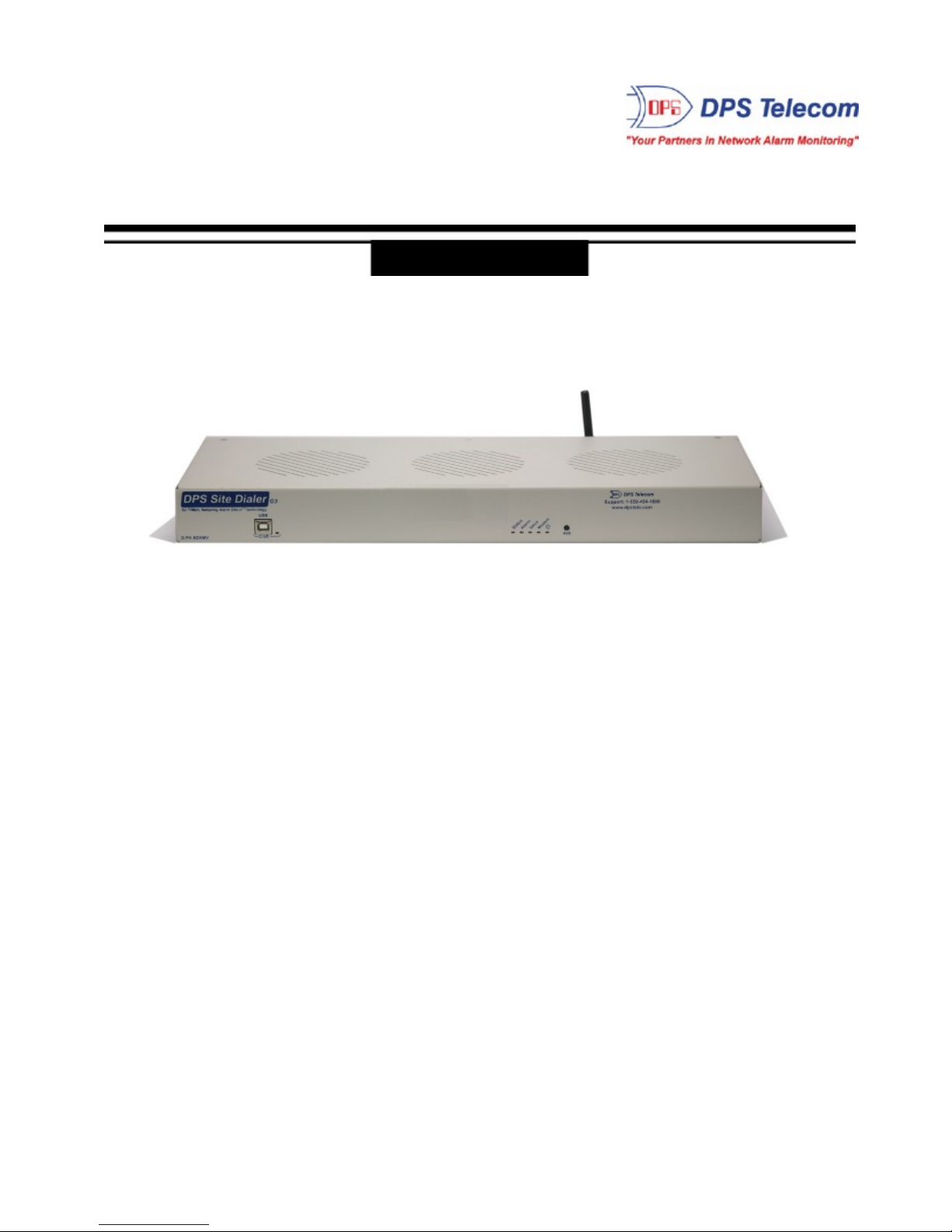
Site Dialer G3
(SDXMV-12004)
USER MANUAL
Visit our website at www.dpstel ecom.com for the latest PDF manual and FAQs.
April 12, 2016
D-UM-SDXMV
Page 2

Revision History
April 12, 2016
Initial Release
This document contains proprietary information which is protected by copyright. All rights are reserved. No part of this
document may be photocopied without prior written consent of DPS Telecom.
All software and manuals are copyrighted by DPS Telecom. Said software and manuals may not be reproduced, copied,
transmitted or used to make a derivative work, by either mechanical, electronic or any other means in whole or in part,
without prior written consent from DPS Telecom, except as required by United States copyright laws.
© 2016 DPS Telecom
Notice
The material in this manual is for information purposes and is subject to change without notice. DPS Telecom shall not be
liable for errors contained herein or consequential damages in connection with the furnishing, performance, or use of this
manual.
Page 3

Page 4

Contents
Visit our website at www.dpstelecom.com for the latest PDF manual and FAQs
Site Dialer G3 Overview1 1
Shipping List2 2
Specifications3 3
Hardware Installation4 4
Tools Needed4.1 4
Mounting4.2 4
Power Connection: -48VDC4.3 5
Initial Setup5 6
LAN Connection5.1 6
Logging on to the NetGuardian5.1.1 7
Configuring the NIC Interface5.1.2 7
Site Dialer G3 Configuration for T/Mon SLIM, MINI, and LNX6 9
Step 1: Setup the Voice Pager Job6.1 9
Step 2: Setup the Site Dialer RTU Job6.2 10
Step 3: Create the Site Dialer Device6.3 10
Step 4: Setup Pager Carriers6.4 11
Step 5: How to Setup Pager Schedules6.5 11
Step 6: How to Setup Pager Profile6.6 12
Step 7: How to Assign Notification to Alarm6.7 12
Step 8: Define Voice Format6.8 13
Site Dialer G3 - Quick Turn Up7 14
How to Send Email Notifications7.1 14
How to Send SNMP Traps7.2 17
Provisioning Menu8 20
System8.1 21
User Profiles8.2 22
Ethernet8.3 24
Notifications8.4 25
Edit8.4.1 26
Email8.4.2 27
SNMP8.4.3 28
Schedule8.4.4 28
System Alarms8.5 29
Timers8.6 30
Date and Time8.7 31
System Alarms8.7.1 32
Page 5

Monitoring Menu9 32
Test Call9.1 33
Stats9.2 33
Device Access Menu10 34
Reference Section11 35
Updating Site Dialer G3 Firmware11.1 35
Updating T/Mon Software11.2 36
System Alarms Map11.3 37
Technical Support12 38
T/Mon Gold and Platinum Plans13 39
End User License Agreement14 40
Page 6
1
· Verbally annunciates incoming messages via
phone
· Dials your home or cell phone with alarm
messages already databased in T/Mon
· Ack alarms from anywhere in the field using your
home or cell phone
· Includes built-in web browser for confirming
configuration settings
Site Dialer G3 Overview1
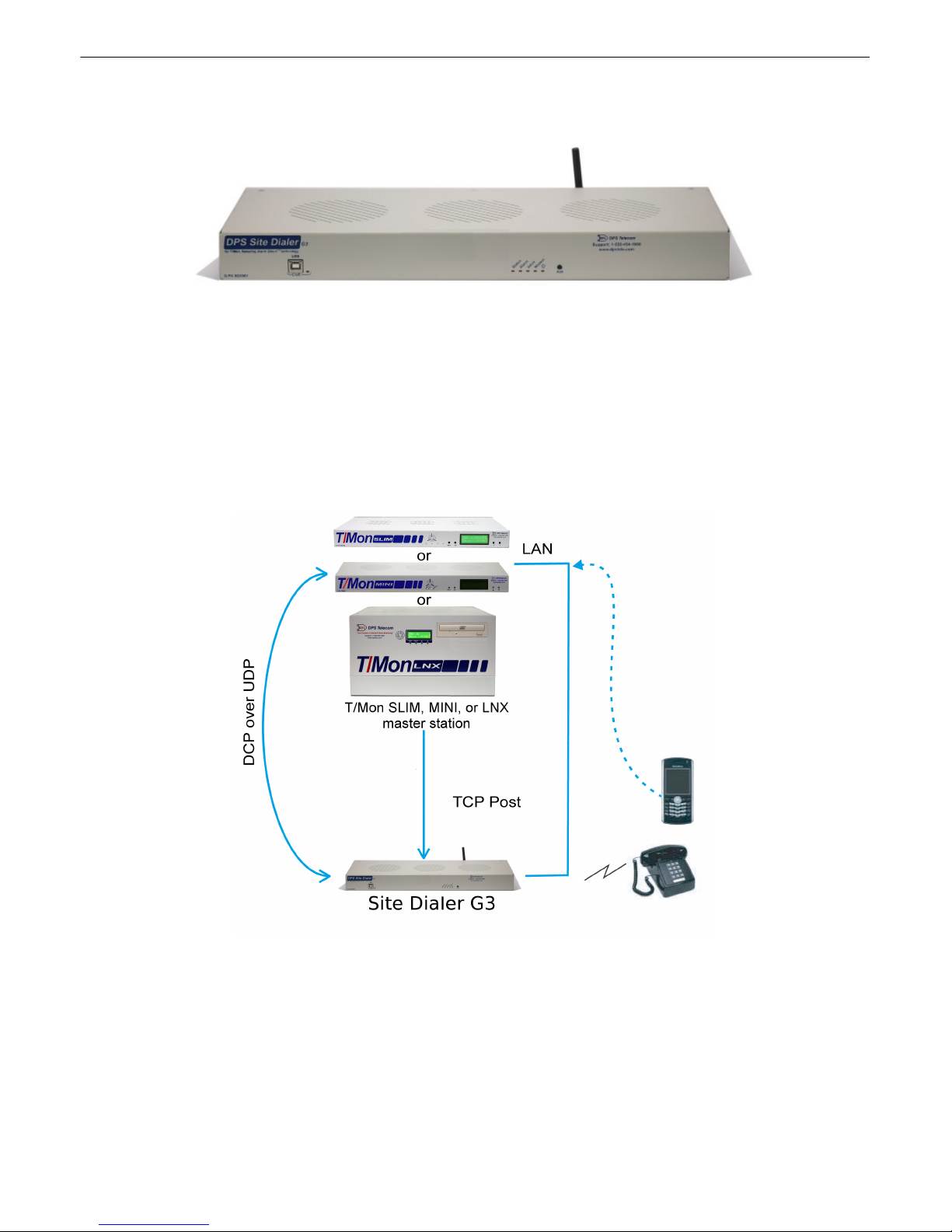
When combined with the T/Mon SLIM, MINI, or LNX master stations, the Site Dialer G3 delivers
another critical method of receiving alarm notifications. This application allows you to receive voice
alerts for the alarm points databased in T/Mon. You can select exactly which alarm points you want to
receive voice notifications for and the Site Dialer G3 calls your home or cell phone with verbal alarm
information. Get the important notifications you need, no matter where you are, via text-to-speech
voice alerts.
The Site Dialer G3 itself is easy to install and requires virtually no configuration. After physically setting
up the unit (mounting, power, and giving it an IP address), you're ready for the configuration on the T/
Mon SLIM, MINI, or LNX.
Immediate benefits of using the Site Dialer G3:
Page 7
Shipping List2
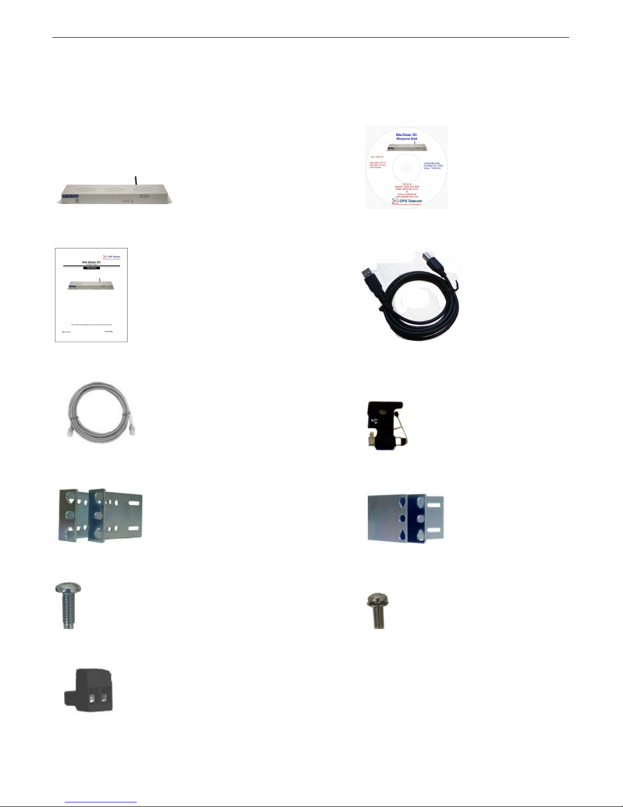
While unpacking the Site Dialer G3, please make sure that all of the following items are included. If some parts
are missing, or if you ever need to order new parts, please refer to the part numbers listed and call DPS Telecom
at (800) 622-3314.
Site Dialer G3 Site Dialer G3 Resource CD
D-PK-SDXMV-12004
2
X1
Site Dialer G3 UM 6 ft. USB Craft Port Cable
D-UM-SDXMV D-PR-046-10A-06
X1 X3
Ethernet Cable - 14 ft Three 3/4 Amp GMT Fuses
D-PR-923-10B-14 2-741-00750-00
X2 X2
19" Rack Ears 23" Rack Ears
D-CS-325-10A-00 D-CS-325-10A-01
X4 X8
Four Rack Screws Eight 3/8" Ear Screws
1-000-12500-06 2-000-60375-0
Power Connectors
2-820-00862-02
Page 8

3
Dimensions:
1.72"H x 17"W x 6.64"D
Modem:
33.6K, Cellular
1
Mounting:
19” or 23” rack or wall mount
Weight:
3.8 lbs. (1.72 kg)
Discrete Alarm Inputs:
N/A2 Discrete Alarm Length:
N/A
Power Input:
Dual -48VDC power feeds (-36VDC to -60VDC)
Analogs:
N/A
Input Range:
N/A4 Analog Accuracy:
N/A
Control Outputs:
N/A
Max Voltage:
N/A3 Current Draw:
350mA @ -48 VDC
Max Current:
N/A
Fuse:
Dual 3/4 Amp GMT
1
Power Outputs:
N/A
Voltage Output
Options:
N/A
Operating Temp:
32° to 140°F (0° to 60°C)
Output Current:
N/A1 Industrial Oper ating Temp:
-22° to 158°F (-30° to 70°C)
Output Fuse:
N/A
Storage Temp:
N/A
Operating Humidity:
0% to 95% (non-condensing)
Audible Interfaces:
N/A
Visual Interfaces:
12 LEDs
MTBF:
60 Years
RoHS:
5/61 Hardware Interfaces:
1 RJ45 10/100BaseT full-duplex Ethernet port
1 USB5 debug/craft port
Ordering Options:
N/A
1 RJ11 Telco jack
Downloadable
Firmware:
Yes1 D-Wire Sensor Support:
N/A
Built-in Web Interface:
Yes
Browser Support:
IE9, IE10, Firefox, Chrome...
Ping Alarms:
N/A
Protocols:
DCPx, TELNET, HTTP, Email….
SNMP Support:
V1, V2C, V3
OS Support:
XP, Vista, 7 (32 or 64 bit)
* This equipment has been tested and found to comply with the limits for a Class A digital device, pursuant to part 15 of the FCC Rules. These limits are designed to provide
reasonable protection against harmful interference when the equipment is operated in a commercial environment. This equipment generates, uses, and can radiate radio
frequency energy and, if not installed and used in accordance with the instruction manual, may cause harmful interference to radio communications. Operation of this
equipment in a residential area is likely to cause harmful interference in which case the user will be required to correct the interference at his own expense.
Specifications3
Hardware
Software
Note:
1
Valid if hardware option is included.
2
Minimum lengths determined with TTL voltage level alarms. Actual distance may vary.
3
Current measured at rated voltage with all controls latched and all alarms triggered.
4
See analog section in manual for detailed analog accuracy breakdown.
5
We always recommend checking for ground potentials before using the USB port and suggest using a USB isolation device for a dditional protection. Without USB isolation,
ground potentials can damage yo ur computer and/or equipment and adversely impact warranty coverage.
Page 9
Hardware Installation4
Fig. 4.2.2
Fig. 4.2.3
Tools Needed4.1
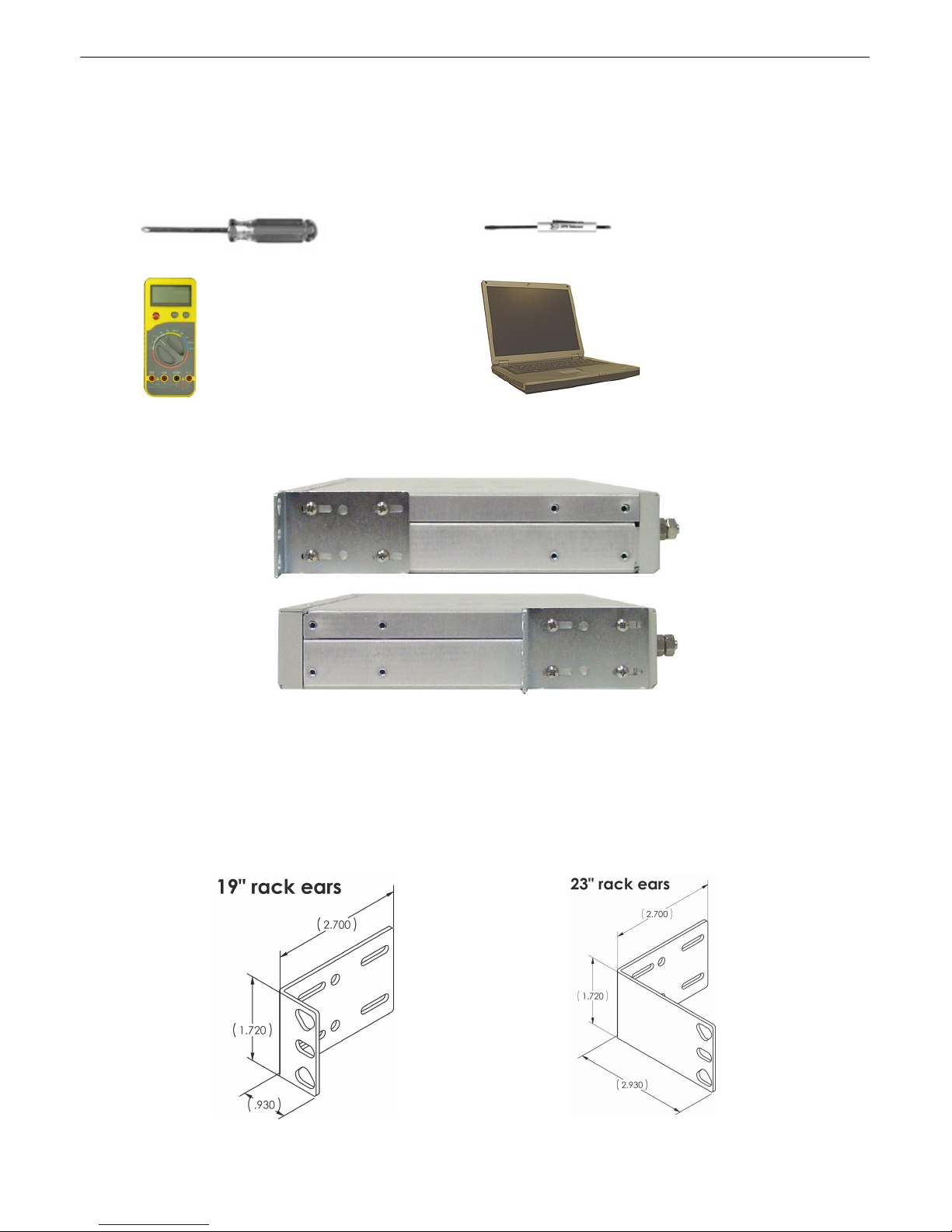
To install Site Dialer G3, you'll need the following tools:
Phillips No. 2 Screwdriver Small Standard No. 2 Screwdriver
Voltmeter PC with T/AccessMW software
Mounting4.2
4
Fig. 4.2.1. Site Dialer G3 can be flush or rear-mounted
WARNING: Leave one rack unit vacant above the Site Dialer G3 to provide adequate heat ventilation.
Site Dialer G3 mounts in a 19" rack or a 23" rack using the provided rack ears for each size. Two rack
ear locations are provided. Attach the appropriate rack ears in the flush-mount or rear-mount locations
shown in Figure 4.2.1.
Note: Rack ears can be rotated 90° for wall mounting or 180º for other mounting options.
Page 10
5
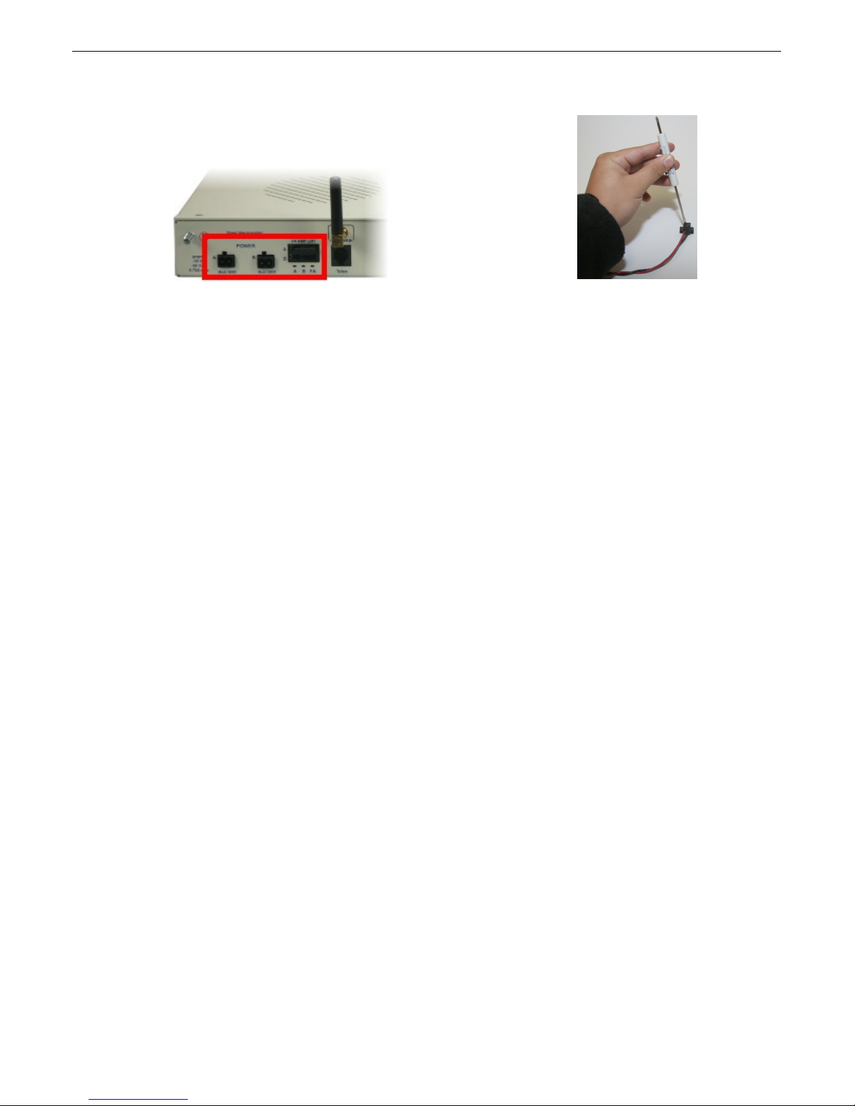
Fig. 4.3.1. Power connectors and fuses
Fig. 4.3.2 Inserting the wires into the
connector
Power Connection: -48VDC4.3
Site Dialer G3 has two terminal barrier plug power connectors, located on the left side of the back
panel. (See Figure 4.3.1.)
Before you connect a power supply to Site Dialer G3, test the voltage of your power supply:
· Connect the black common lead of a voltmeter to the ground terminal of the battery.
· Connect the red lead of the voltmeter to the battery's –48 VDC terminal.
· The voltmeter should read between –18 and –60 VDC. If the reading is outside this range, test
the power supply.
To connect Site Dialer G3 to a power supply, follow these steps:
1. Remove the fuses from the back panel. Do not reinsert the fuse until all power connections
have been made.
2. To ground Site Dialer G3, connect a grounding wire to the grounding lug.
3. Remove the power connector plug from Power Connector A.
Note that the plug can be inserted into the power connector only one way — this ensures that
the barrier plug can only be reinserted with the correct polarity.
Note that the –48V terminal is on the left and the GND terminal is on the right.
4. Insert a battery ground into the power connector plug's right terminal and tighten the screw.
5. Insert a –48 VDC line to the plug's left terminal and tighten its screw.
6. Push the power connector plug firmly back into the power connector. If the power feed is
connected correctly, the LED by the connector will light GREEN. If t he polarity of the power
feed is reversed, the LED by the power connector will be OFF.
7. Repeat Steps 2–4 for Power Connector B.
8. Reinsert the fuse to power Site Dialer G3. The front panel LEDs will blink RED and GREEN
after 20–30 seconds.
Page 11
Initial Setup5
LAN Connection5.1
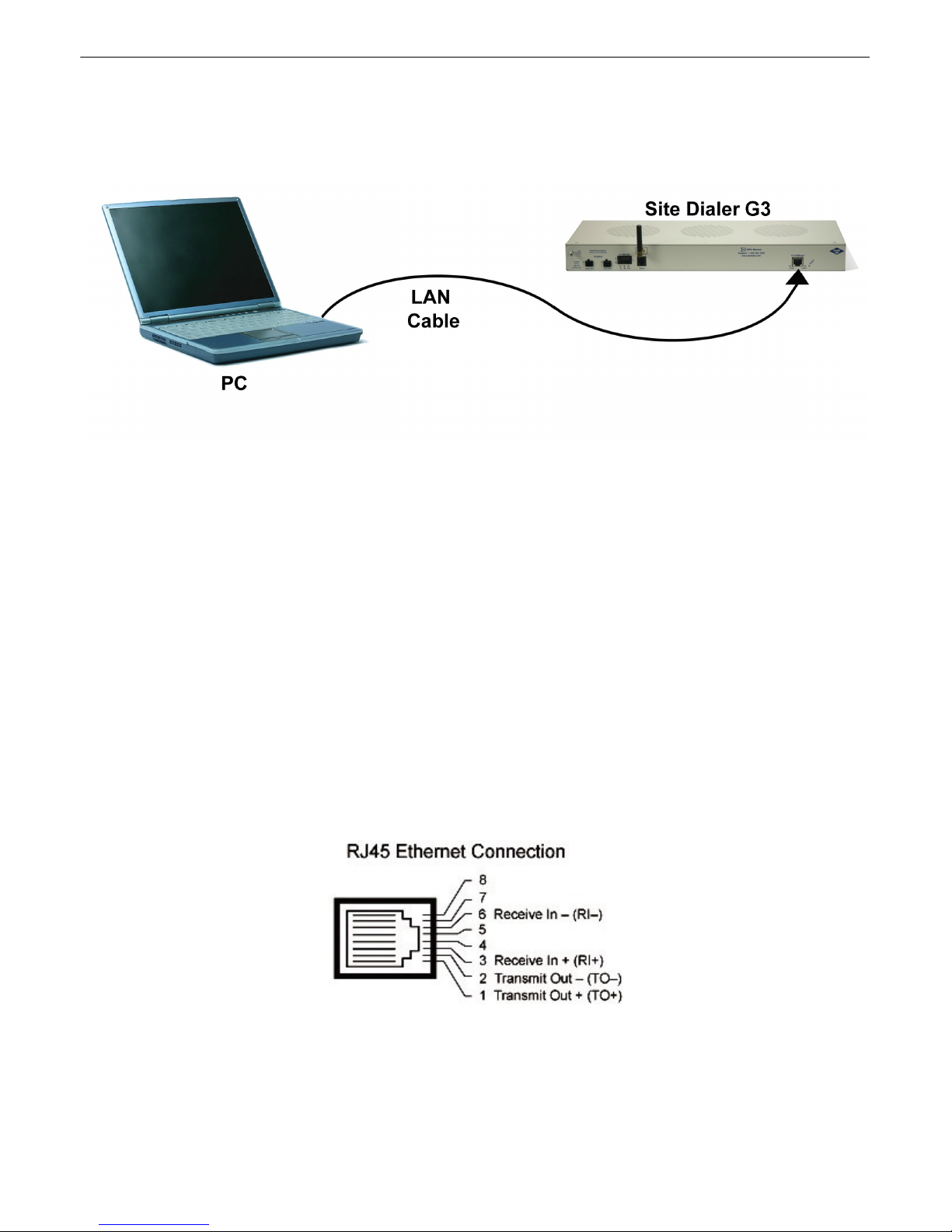
To connect to the Site Dialer G3 via LAN, all you need is the unit's IP address (Default IP address is
192.168.1.100).
6
If you DON'T have LAN, but DO have physical access to the Site Dialer G3, connect using a LAN crossover
cable. NOTE: Newer PCs should be able to use a standard straight-through LAN cable and handle the crossover
for you. To do this, you will temporarily change your PC's IP ad dress and subnet mask to match the NetGuardian's
factory default IP settings. Follow these steps:
1. Get a LAN crossover cable and plug it directly into the Site Dialer G3's LAN port.
2. Look up your PC's current IP address and subnet mask, and write this information down.
3. Reset your PC's IP address to 192.168.1.200. Contact your IT department if you are unsure how to do
this.
4. Reset your PC's subnet mask to 255.255.0.0. You may have to reboot your PC to apply your changes.
5. Once the IP address and subnet mask of your computer coincide with the unit, you can access the Site
Dialer G3 via a Telnet session or via Web browser by using the unit's default IP address of 192.168.1.100.
6. Provision the Site Dialer G3 with the appropriate information, then change your computer's IP address
and subnet mask back to their original settings.
Now you're ready to do the rest of your configuration via LAN.
Ethernet port pinout
Page 12
7
!
Hot Tip!
The max. number of users allowed to simultaneously access the Site Dialer G3 via the Web is
1.
5.1.1 Logging on to the NetGuardian
For Web Interface functionality, the unit must first be configured with some basic network information. If this step
has not been done, refer to the section "Quick Start: How to Connect to the NetGuardian" for instructions on initial
configuration setup.
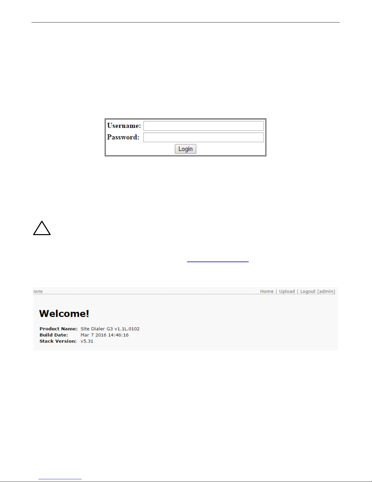
1. To connect to the NetGuardian from your Web browser, enter its IP address in the address bar of your web
browser. It may be helpful to bookmark the logon page to avoid entering this each time.
2. After connecting to the unit's IP address, enter your login information and click OK. NOTE: The factory default
username is "admin" and the password is "dpstelecom".
Enter your password to enter the device's Web Browser Interface
3. In the left frame you will see the Monitor menu (blue), Provisioning menu (green), and Device Access
menu (pink). The Monitor menu links are used to view the current status of alarms. The Provisioning menu
is used to change the unit's configuration settings. All the software configuration will occur in the Provisioning
menu. The Device Access menu provides access to configuration files and Reboot option. The following
sections provide detailed information regarding these functions.
5.1.2 Configuring the NIC Interface
1. Open an Internet browser and navigate to the IP: http://192.168.1.100.
2. Login with the default username of "admin" and password "dpstelecom"
3. In the left menu, select Provisioning, then select Ethernet.
4. From the Ethernet Settings page, modify IP Address, Subnet Mask, and Gateway as necessary.
Page 13
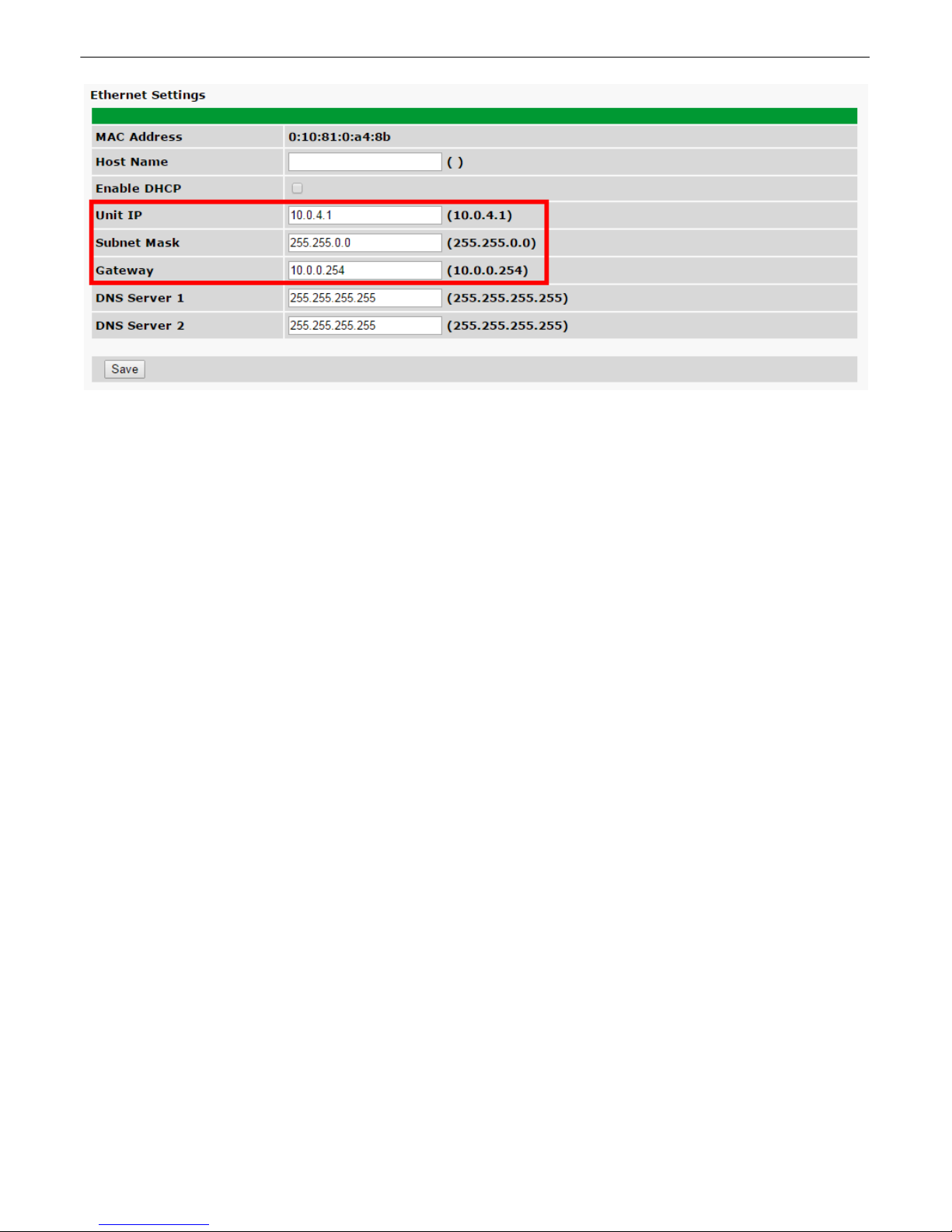
5. Select Save.
8
Page 14
9
Site Dialer G3 Configuration for T/Mon SLIM, MINI, and
6
LNX
Most of the configuration for this application is done on the T/Mon SLIM, MINI, or LNX. The Site Dialer
G3 only requires that the hardware be setup and that the unit has an IP address.
In order for the Site Dialer G3 application to work, you'll need the following components:
· T/Mon SLIM, MINI, or LNX
· Site Dialer G3 software module for T/Mon
The following steps assume you already have the following configured in your T/Mon. For help, see the
T/Mon manual.
· Pager Job
· Ethernet Job
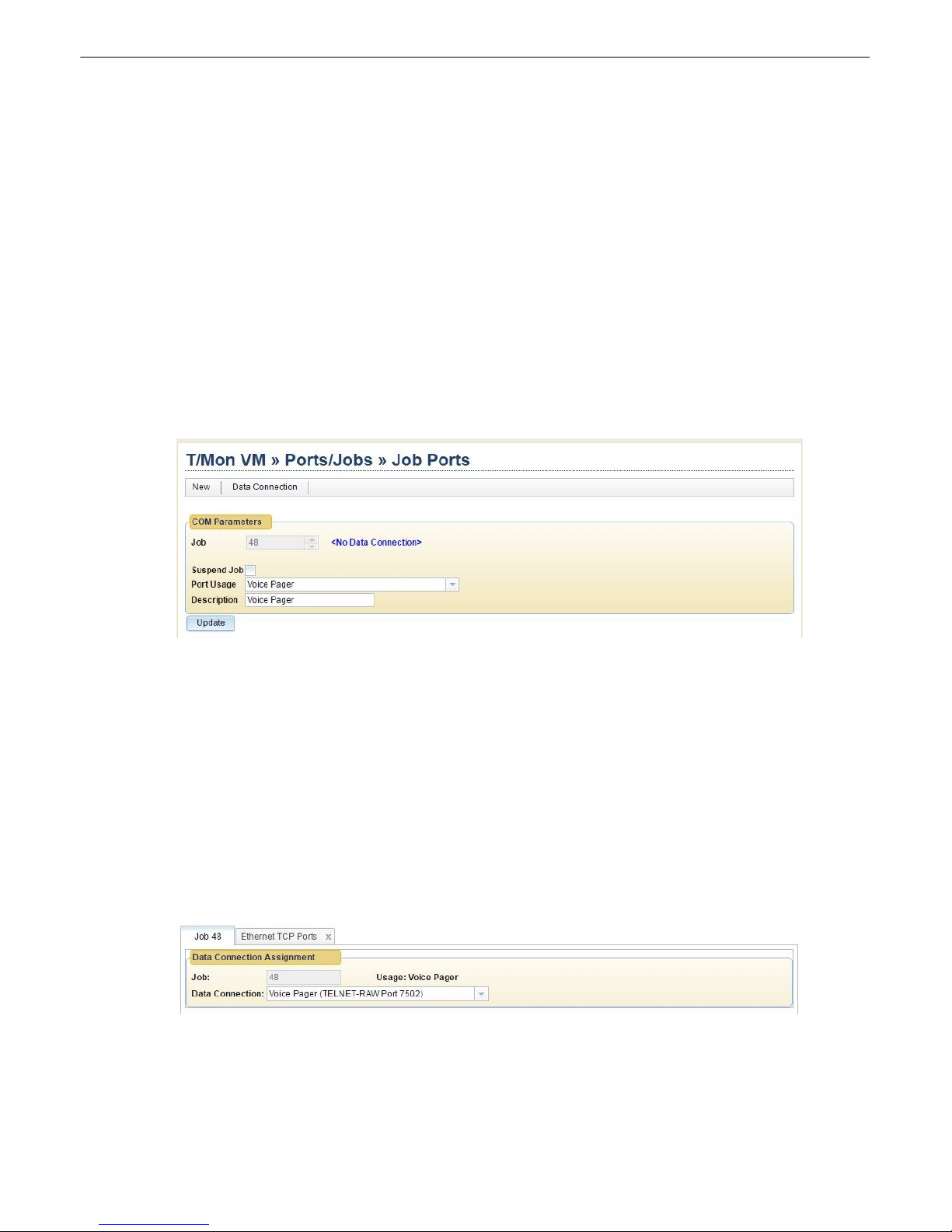
Step 1: Setup the Voice Pager Job6.1
1. Log in to the Edit portion of T/Mon. Click Ports/Jobs, then Job Ports.
2. On the Job Ports screen, select a COM port above 47.
3. Under the Port Usage drop-down, select Voice Pager (This is the job that “talks” to the T/ Mon).
4. Enter a description (optional) and click Create. You will see “<No Data Connection>” at the top
of the container.
5. Click Data Connection on the menu bar, then Tcp Ports at the bottom of the container.
6. Add a new data connection by clicking Add. Fill in the new line with the following information:
a. Type: TELNET-RAW
b. IP / Host Name: 127.0.0.1
c. T CP Port: 7502. ( Port 7502 is config ur ed in Exp_config.ini on LNX: "/exec/VoiceDialer/
VoiceDialer -p 7502". If no parameter, then port is set to 7502).
d. Description: Enter a description here, such as ‘Voice Pager’.
e. Save changes and return to the Job tab.
7. Select TELNET-RAW Port 7502 as Data Connection.
8. Click Save.
Page 15
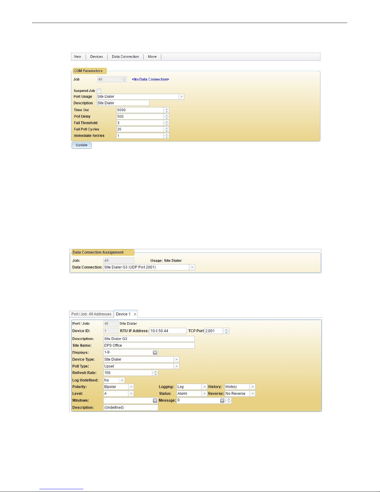
Step 2: Setup the Site Dialer RTU Job6.2
1. Return to the Ports/Jobs > Job Ports screen.
2. Choose the next open port, and change Port Usage to Site Dialer (This is the job that “talks” to
the Site Dialer).
3. Description is optional. Feel free to leave the default values for Time Out, Poll Delay, Fail
Threshold, Fail Poll Cycles, and Immediate Retries. Save the job.
4. Click Data Connection in the top menu, then Tcp Ports at the bottom of the container.
5. Add a new TCP port with the following information:
a. Type: UDP (DPS RTU, SNMP Trap Processing, SNMP Agent).
b. TCP Port: 2001 (or any available port).
c. Description: Enter a description here, such as “Site Dialer G3”.
d. Save changes and return to the Job tab.
6. Select "Site Dialer G3 (UDP Port 2001)" as the Data Connection.
10
7. Save.
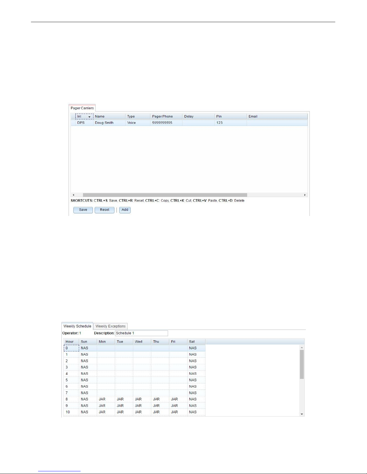
Step 3: Create the Site Dialer Device6.3
1. Back on the Site Dialer's Job Port screen, click the Devices button on the menu bar, then Add a
device.
2. Enter the Device ID. The default is 1, unless you’ve changed it (This is the DCP address of the
unit).
Page 16
11
3. Enter in the IP address and port (default is 2001) of the Site Dialer G3.
4. Description and Site Name are optional.
5. For Device Type, select Site Dialer. (This is the only option).
6. You can leave the other fields as default or customize as you see fit.
7. Save the device.
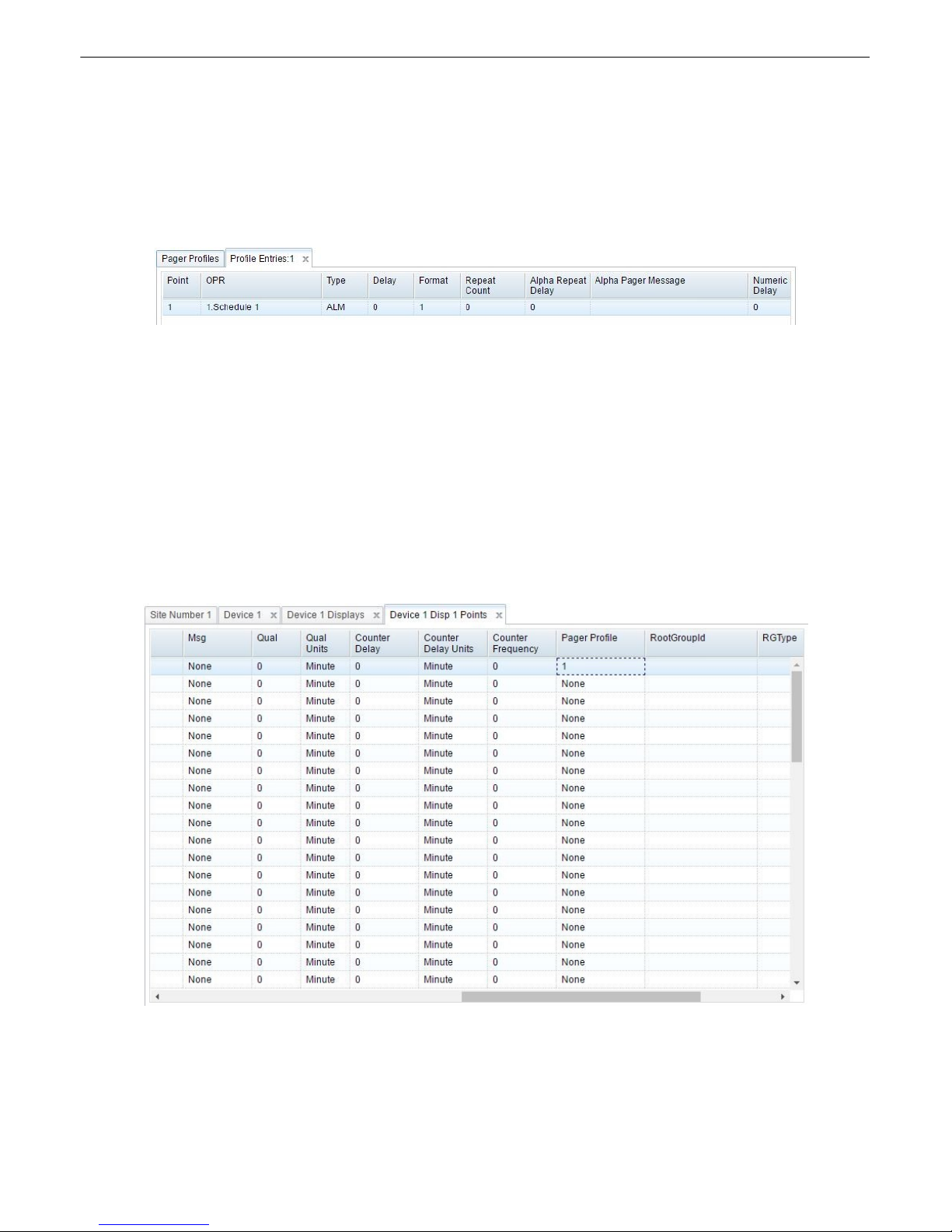
Step 4: Setup Pager Carriers6.4
1. Go back to the main menu and choose Notifications > Targets/Groups. This is where you add
your technicians, who get called when an alarm comes in.
2. Add a pager carrier by pressing Add.
3. Enter in the Int (Initials) and Name for your technicians.
4. For Type, select Voice.
5. For Pager/Phone, enter the phone number to call.
6. The Pin field should be filled in for added security. This is the ID you’ll press on your phone to
acknowledge an alarm. Example: If your ID is 123, you’ll press 123# to ack an alarm from your
phone. If you did not enter in an ID, you’ll simply press # to ack.
7. Finish entering in all your operators and then Save.
Step 5: How to Setup Pager Schedules6.5
1. G o t o Notifications > Weekly Schedules from the main menu.
2. Enter an operator number and a description of t he schedule, then hit Create.
3. I n t he g r id on the Weekly Schedule tab, configure when you want each pager carrier to receive
Page 17
notifications. HINT: You can fill boxes more quickly by right clicking and pressing Fill. In the popup,
you can assign a pager carrier to specific days and hours more easily. Also, you may opt to only
have one technician per schedule.
4. I f applicable, you can configure exceptions to these rules (such as on holidays) in the Weekly
Exceptions tab.
5. Save changes when finished.
Step 6: How to Setup Pager Profile6.6
1. G o t o Notifications > Profiles.
2. Add a profile and give it a description, then Save.
3. Right - click t he profile you created and select Entries.
4. Under OPR, select the weekly schedule you just set up.
5. Under type, select the condition that must be fulfilled to send a notification, i.e. ALM for alarm, CLR
for clear, or BOTH.
6. Under delay, enter the number of m inutes you want the condition to be met before sending the
notification.
7. Leave Format set to 1 because there is only 1 configurable voice message format.
8. I gnore the other fields, as they do not apply to voice notifications.
12
Step 7: How to Assign Notification to Alarm6.7
1. Fr om t he main menu, select LAN-based remotes, then NetGuardian/NetDog_G2.
2. Select a Site fr om t he list on the left , or add a new site/remote.
3. Click Device Definition on the bottom, then Point Definitions, then double-click the display containing
the alarm point you want to send the notification.
4. Find the alarm point which you want to send the voice notification and scroll to the right until you see
the Pager Profile column. Enter the number of a pager profile you have set up, such as 1.
Page 18
13
5. The alarm point should now send voice notifications based on the selected pager profile, and the
underlying pager schedule and pager carriers.
Step 8: Define Voice Format6.8
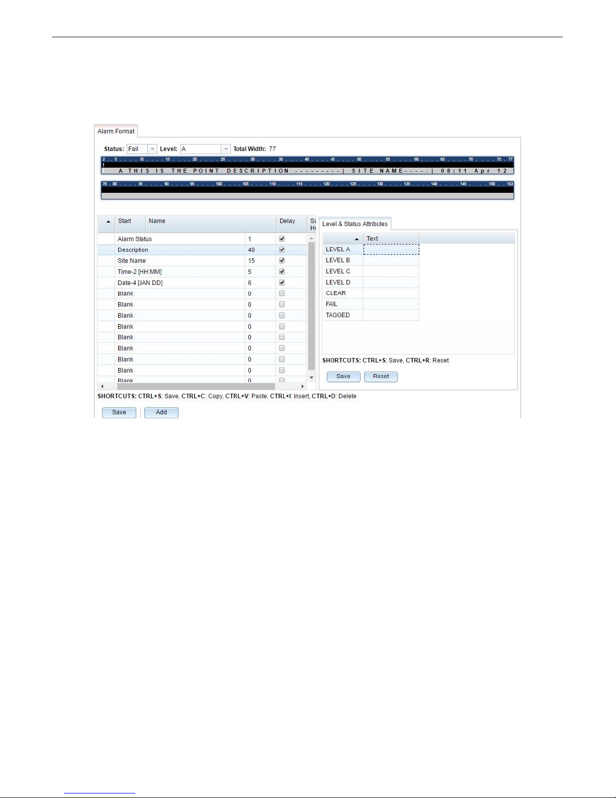
1. Fr om t he main menu, select Notif ications, then Voice Message Format.
2. Each row in the left table is something that will be said in the voice message. Set the names to
things you want the message to include, such as Alarm Status, Site Name, Time, Date, etc. The
message parts will be said in the order you specify.
3. The Delay field specifies how much of the message is allotted to that clause. If the content is longer
than the space allotted, it will be truncated.
4. Check Say Header if you want the label to be said before the content. For example, the description
field would say "SITE NAME Headquarters" if checked, or just "Headquar t ers" if unchecked.
5. The bar-shaped display at the top is the timeline of the message. Adjust until message format is
suitable, then Save your changes.
Page 19
Site Dialer G3 - Quick Turn Up7
The next 2 sections of this manual will walk you through some of the most common tasks for using the Site Dialer
G3. You will learn how to send e mail notifications, and send SNMP traps to your alarm master - all using the Web
browser. For details on entering your settings into each Web browser menu, the section "Provisioning Menu Field
Descriptions" section.
How to Send Email Notifications7.1
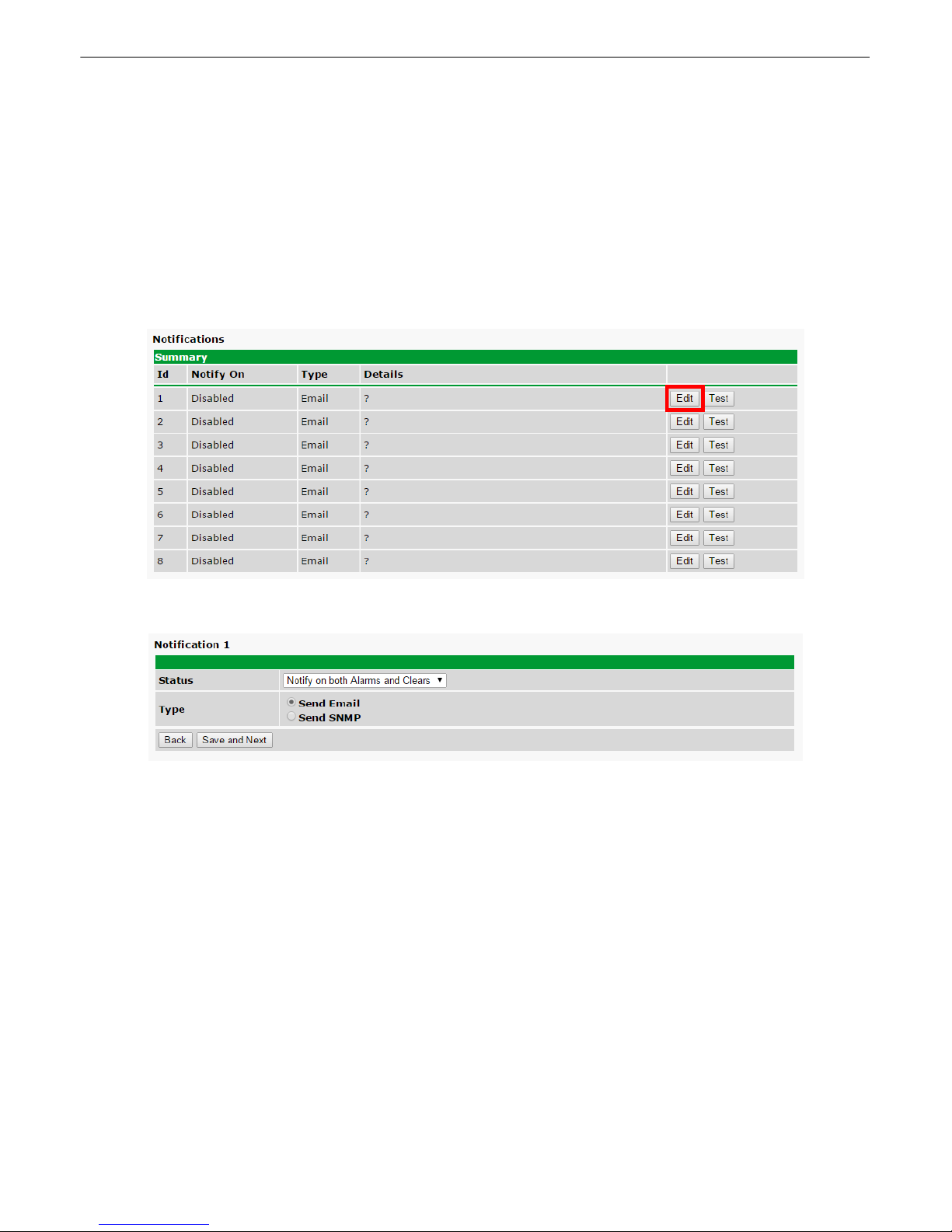
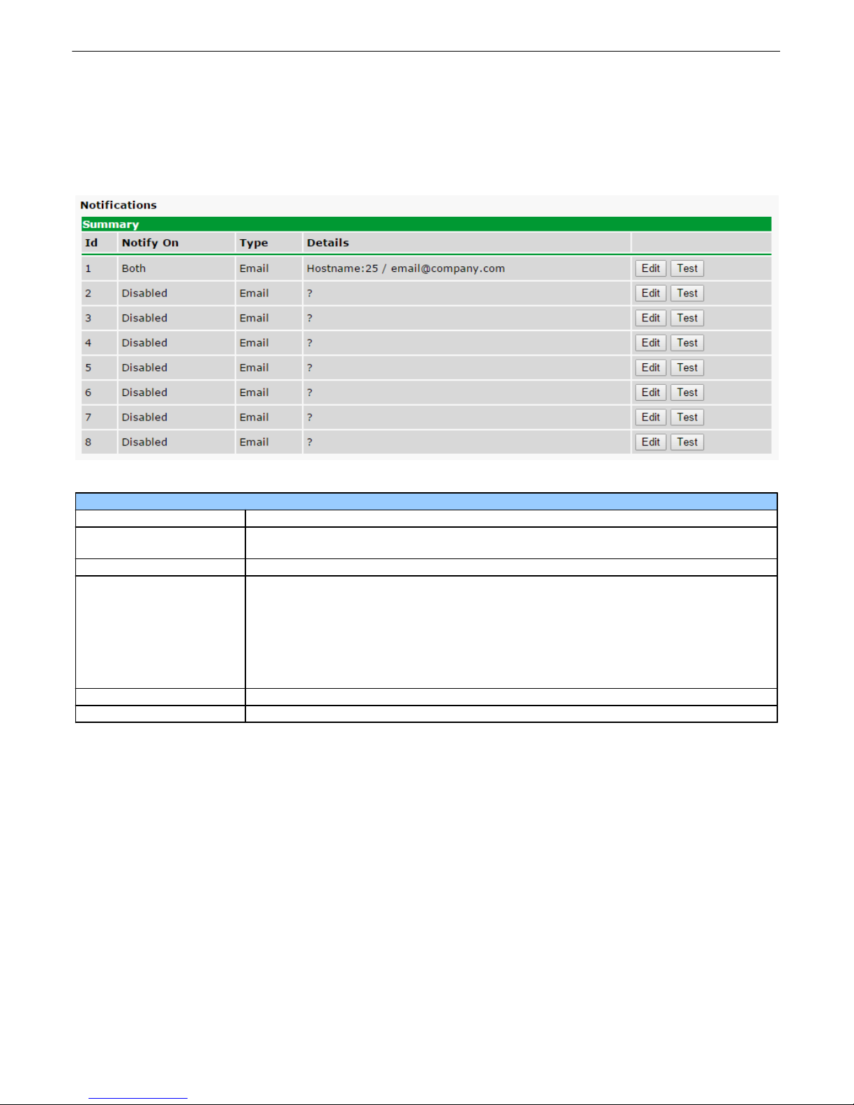
1. Click on the Notifications button in the Provisioning menu. You can setup as many as 8 different notifications.
Begin the setup "wizard" by clicking Edit for a notification number. In this example, we'll setup Notification 1 to
send emails.
14
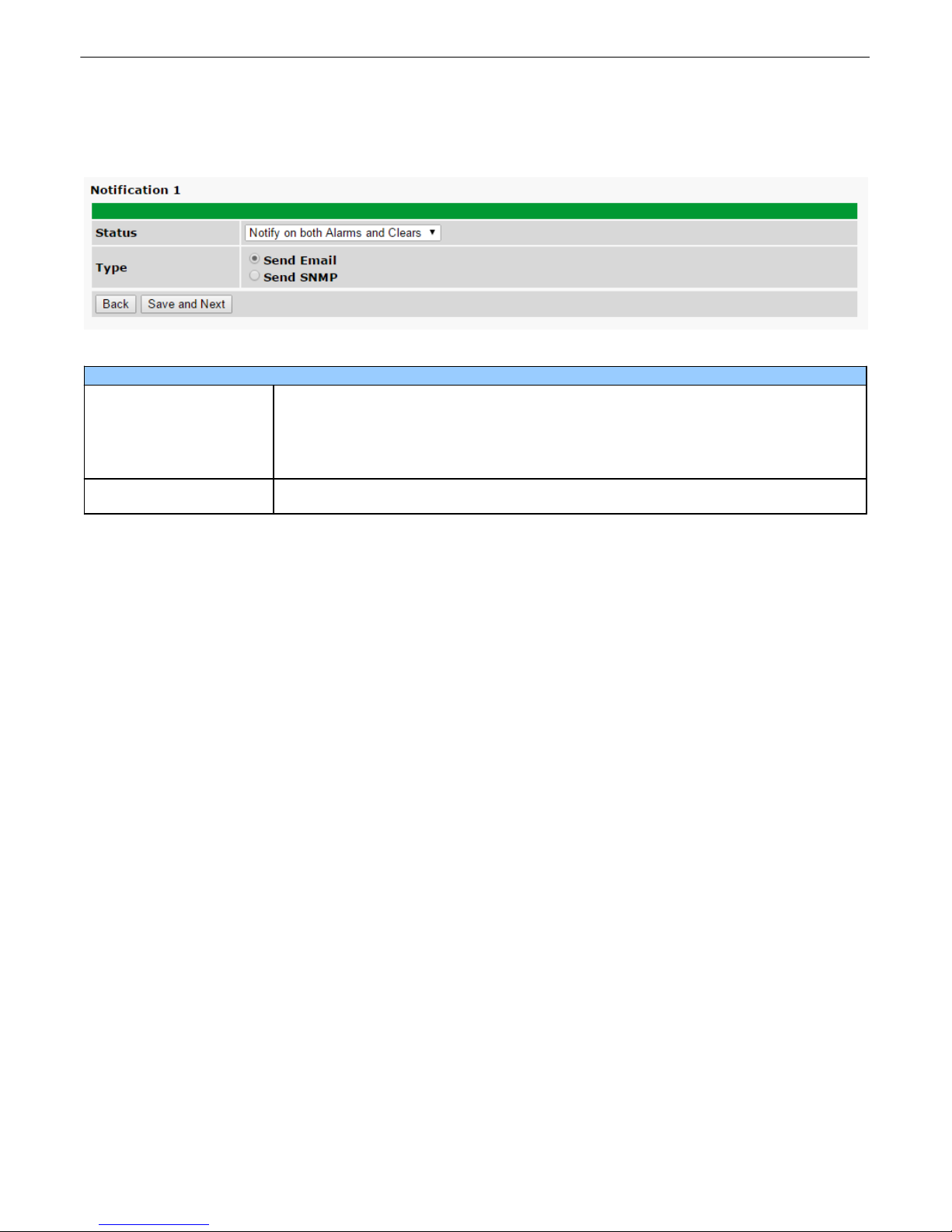
2. At the Notification Setting screen, use the drop down box to set what events to use for this notification. Now,
select the Send Email button and click Save and Next.
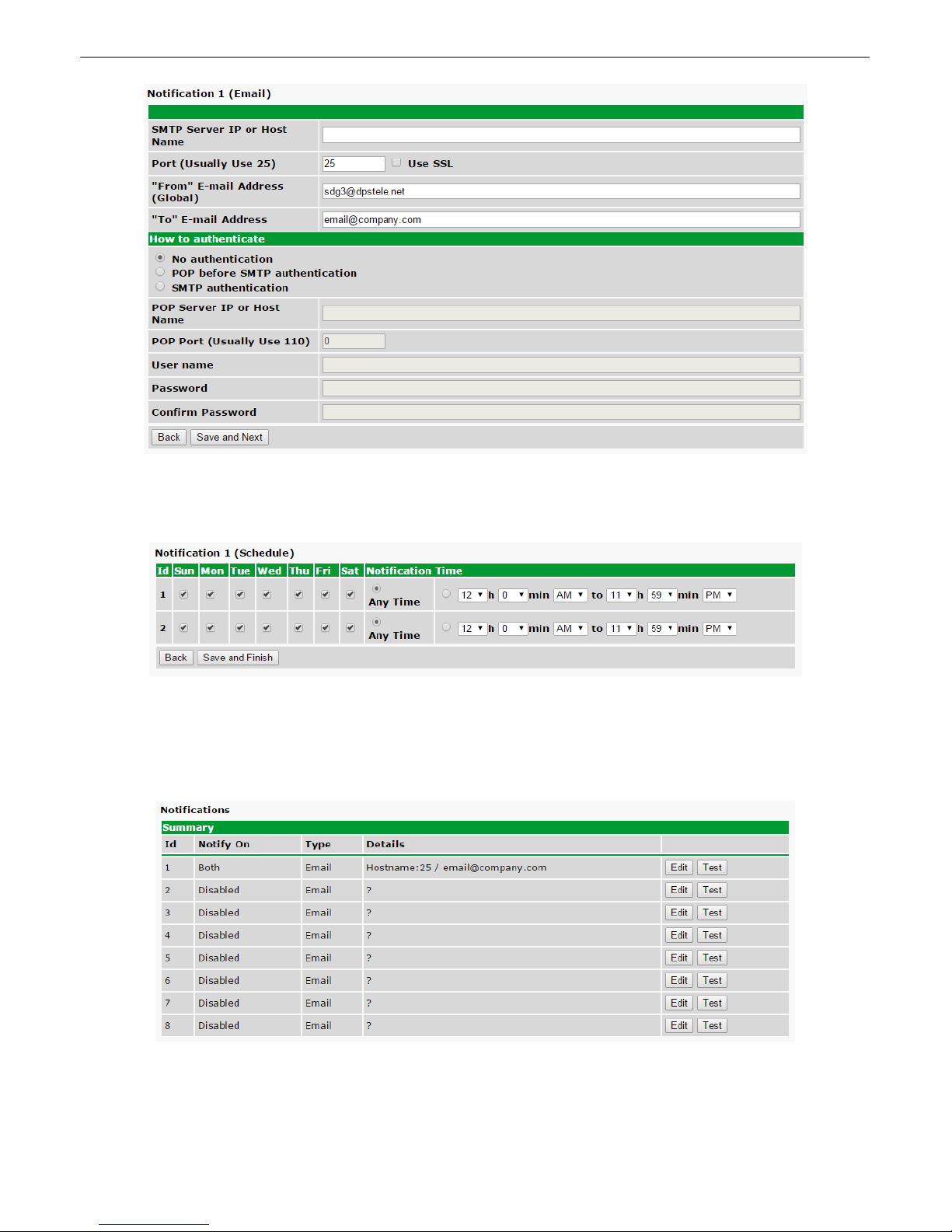
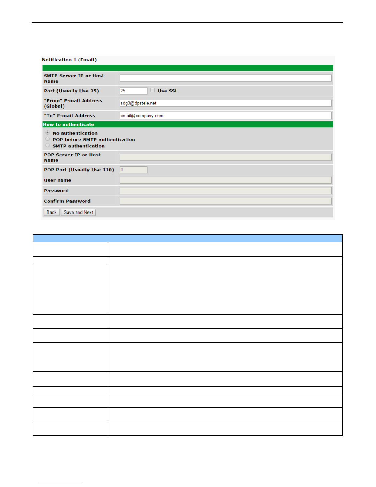
3. At the Email Notification screen, you'll enter your email server settings. Enter the IP address or Host Name of
your email server. Enter the Port Number (usually 25) and the "To" Email Address of the technician that will
receive these emails. If authentication is required, chose the type and fill in the necessary fields. Click Next.
Page 20
15
4. At the Schedule screen, you'll select the exact days/times you want to receive email notifications. You can set
2 schedules per notification. For example, you may want to receive notifications at certain times during the week,
and at different hours on the weekend. Use the check boxes to select the days of the week, and select the time
from the drop down menus. Click Save and Finish.
5. You may want to test the email notification you've just setup, by clicking Test next to the notification. Make sure
you Write your changes under Device Access before attempting a test. You will p rompted with a pop up. Click
OK to send a test email alarm notification. Confirm all your settings by checking your email to see if you've
received it.
NOTE: This test only means that your notification settings are correct, but you still need to assign the notification
to an alarm point. See the next step.
6. Now you will associate this notification to a system alarm. You have 8 notification devices available to use. In
Page 21
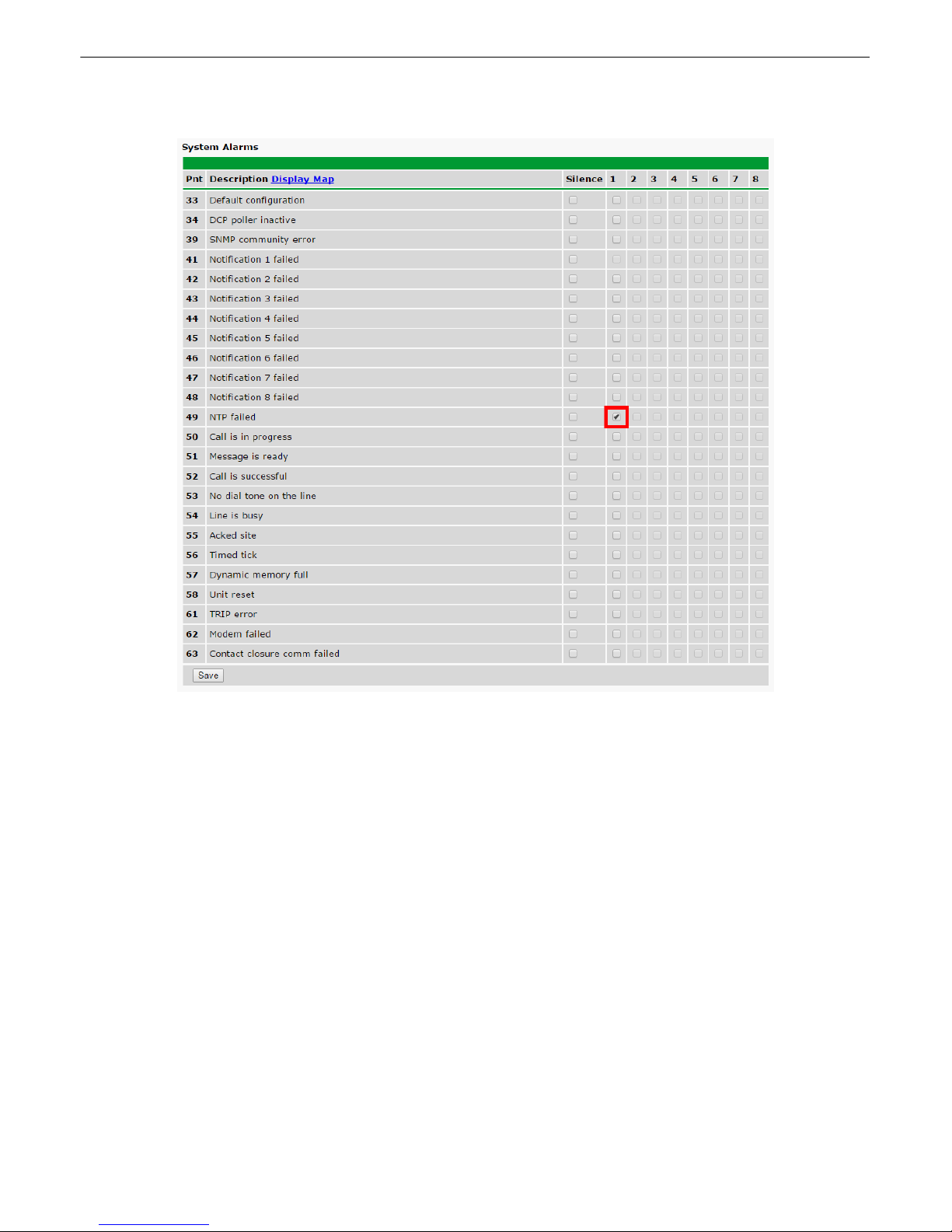
the image below, you might assign Notification Device 1 to System Alarm 49. This means that you would
receive an email notification when an alarm for System Alarm 49 (NTP failed) occurs.
16
Page 22
17
How to Send SNMP Traps7.2
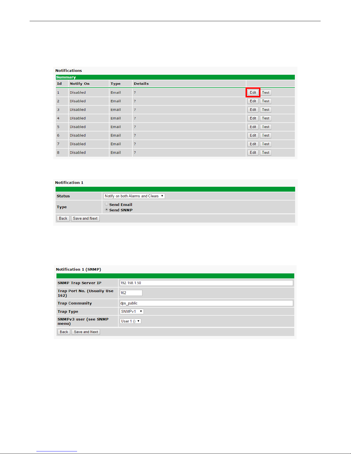
1. Click on the Notifications button in the Provisioning menu. You can setup as many as 8 different notifications.
Begin the setup "wizard" by clicking Edit for a notification number. In this example, we'll setup Notification 1 to
send SNMP messages.
2. At the Notification Setting screen, use the drop down box to set what events to use for this notification. Now,
select the Send Email button and click Save and Next.
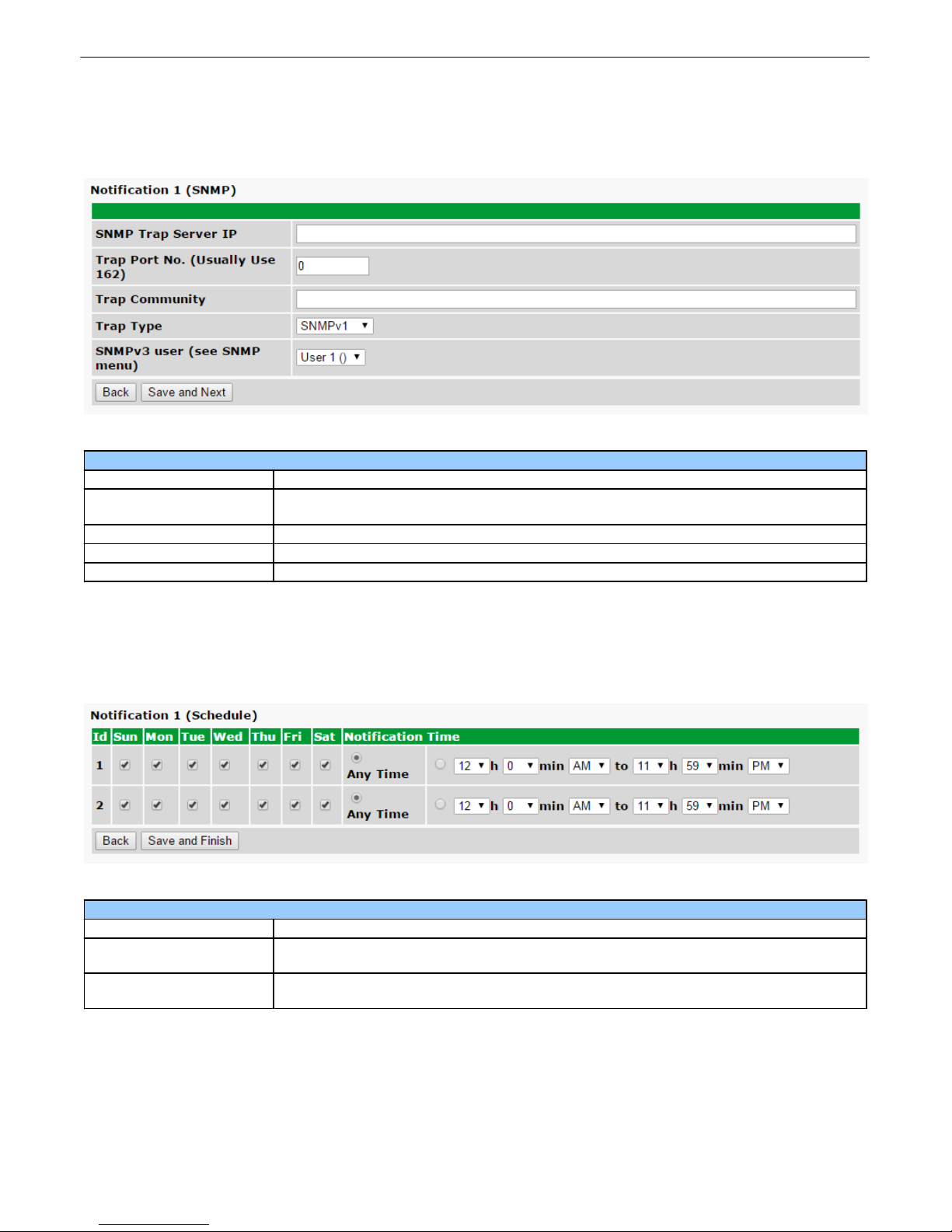
3. At the SNMP Notification screen, you'll enter your network's SNMP settings. Enter the IP address of your
SNMP Trap Server. Enter the Trap Port Number (usually 162), and the Trap Community name. The typical
SNMP community string for network devices is "public". As an added security measure, we've made our default
"dps_public".
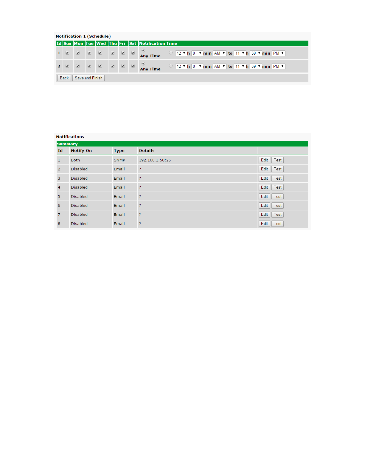
4. At the Schedule screen, you'll select the exact days/times you want to receive SNMP notifications. You can set
2 schedules per notification. For example, you may want to receive notifications at certain times during the week,
and at different hours on the weekend. Use the check boxes to select the days of the week, and select the time
from the drop down menus. Click Save and Finish.
Page 23
5. You may want to test the email notification you've just setup, by clicking Test next to the notification. Make sure
you Write your changes under Device Access before attempting a test. You will p rompted with a pop up. Click
OK to send a test SNMP alarm notification. Confirm all your settings by checking your alarm master to see if the
SNMP trap was received.
NOTE: This test only means that your notification settings are correct, but you still need to assign the notification
to an alarm point. See the next step.
18
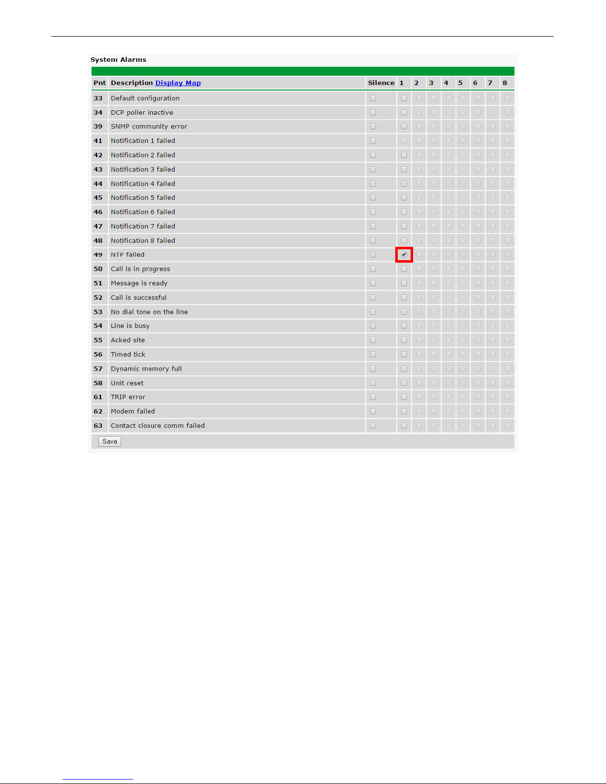
6. Now you will associate this notification to a system alarm. You have 8 notification devices available to use. In
the image below, you might assign Notification Device 1 to System Alarm 49. This means that you would
receive an email notification when an alarm for System Alarm 49 (NTP failed) occurs.
Page 24
19
Page 25
Provisioning Menu8
Site Dialer G3 configuration is performed from the Provisioning menus, the menu options in green on the leftside of the web interface. The following pages provide a brief description of the options available i n each menu.
Saving Configuration Changes to the NetGuardian:
At the bottom of each screen you access from the Provisioning Menu, you will see a Save button. Clicking Save
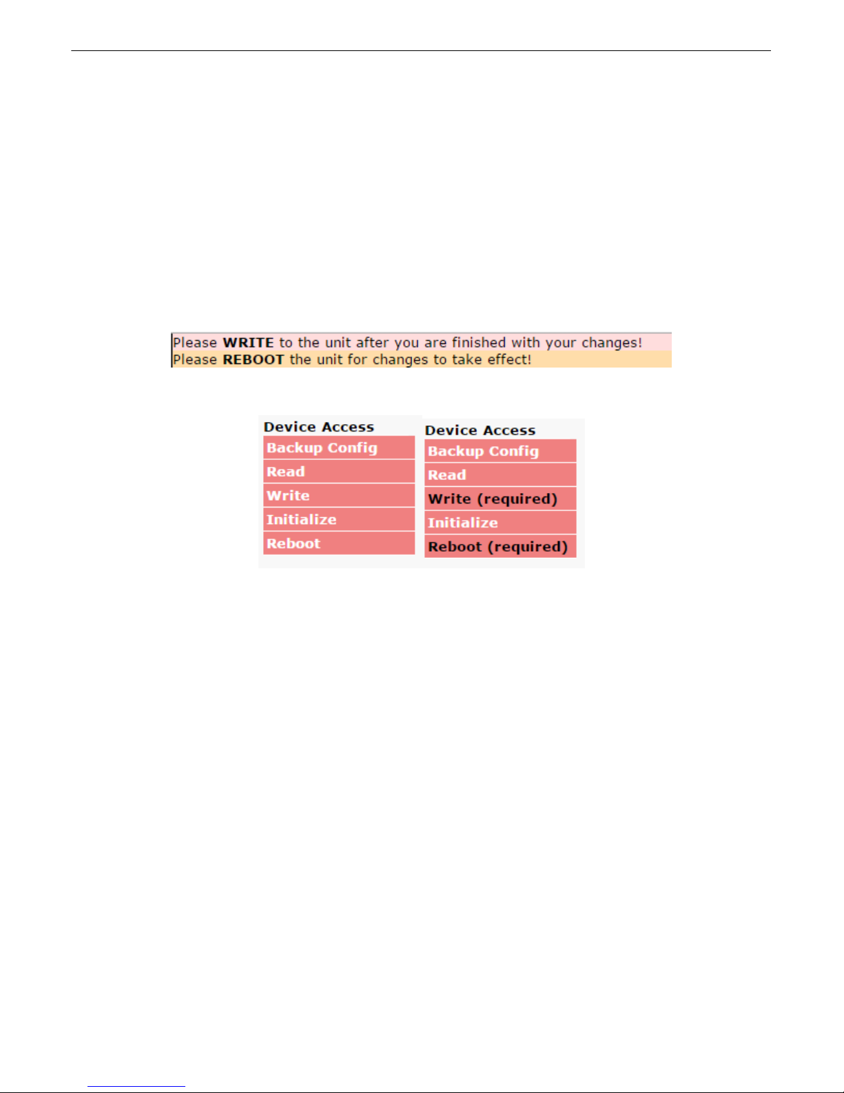
will cache your changes locally. The web interface will then prompt you to either Write your changes to the unit or
Reboot the unit for changes to take effect in the top-left corner of your browser. The relevant options will be
highlighted in the Device Access options.
Note: If the unit prompts you to both Write changes to the unit and Reboot, you will Write your changes first.
Rebooting before without writing to the unit (if a Write is required) will cause you to lose your configuration
changes.
Status messages on the NetGuardian Device Access menu, inform you how to implement your changes
20
The control menu highlights items that must be completed for your changes to take effect
Page 26
21
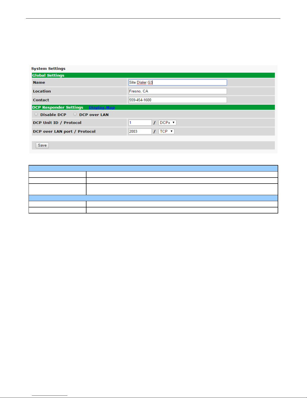
Global System Settings
Name
A name for this NetGuardian unit. (Optional field)
Location
The location of this NetGuardian unit. (Optional field)
Contact
Contact telephone number for the person responsible for this NetGuardian unit.
(Optional field)
DCP Responder Settings (For use with T/Mon)
DCP Unit ID / Protocol
User-definable ID number for the target unit (DCP Address) and desired protocol.
DCP LAN
Enter the DCP port for the target unit (UDP/TCP port) and desired protocol.
System8.1
From the Provisioning > System menu, you will configure and edit the global system settings and DCP
Responder settings.
The Provisioning > System menu
Page 27
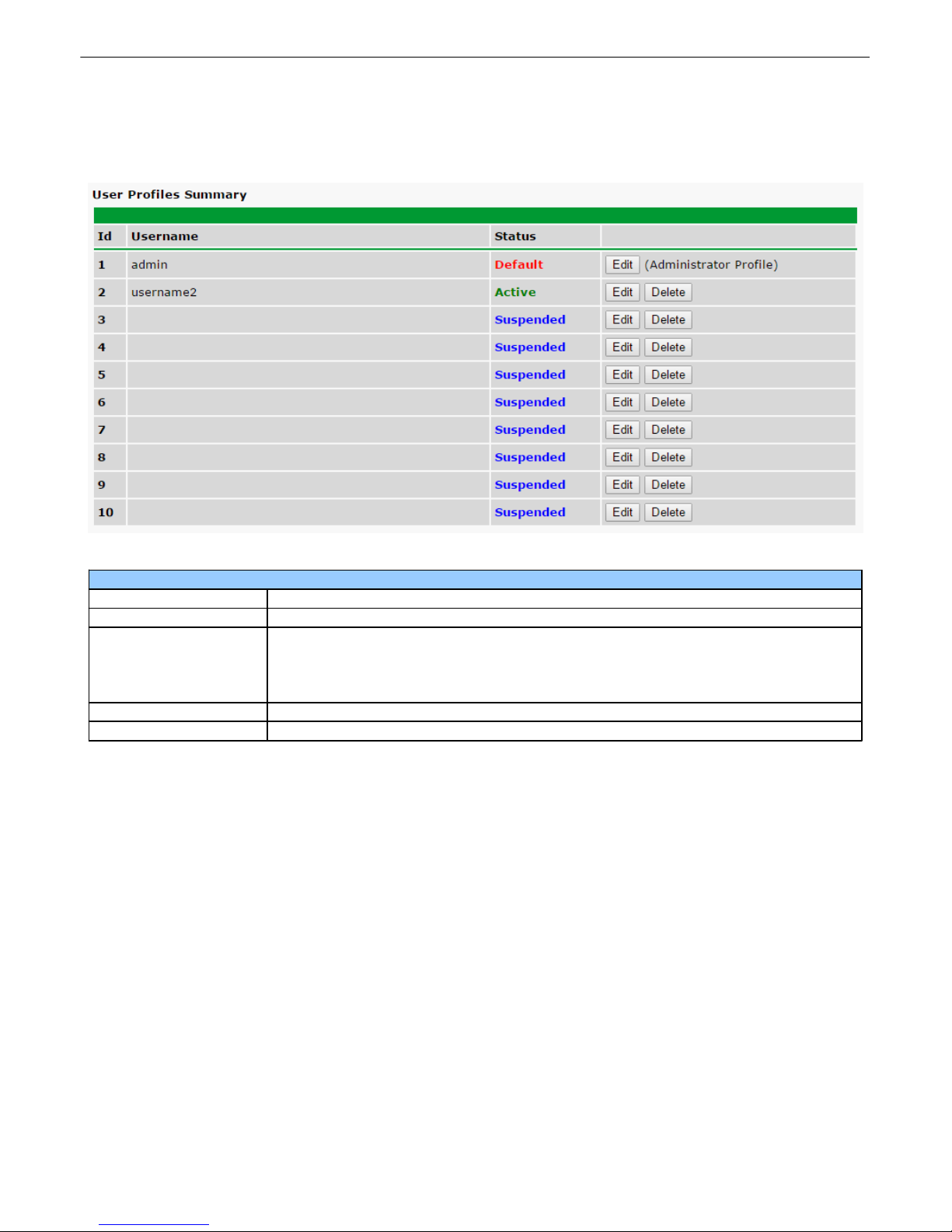
User Profiles8.2
User Profiles Summary
Id
The ID number for the user profile.
Username
The configured name for the user profile. Used for logging into web interface.
Status
The status of the profile. It can be one of the following:
· Default - Reserved for the admin account, which cannot be suspended.
· Active - Indicates the profile is live and can be used to log in.
· Suspended - Indicates the profile is not active and cannot be used to log in.
Edit
Brings up the edit screen for a particular profile.
Delete
Deletes all saved settings for a particular profile.
The User Profiles screen allows you to manage user access to the Site Dialer G3's web interface. You can set
the login information for the admin profile, and create up to 9 more profiles with customizable permissions.
22
The Provisioning > User Profiles screen
Select Edit for any of the 10 profiles to be taken to the Edit Profile screen, which allows yo u to edit username,
password, and access rights.
Page 28
23
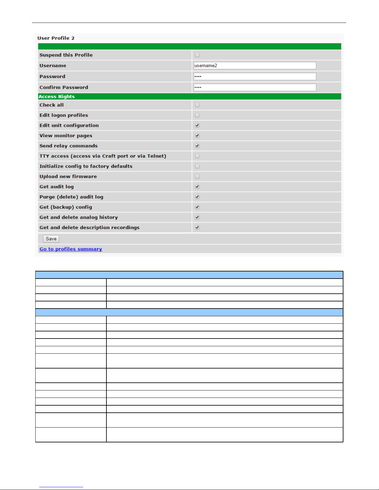
User Profiles Summary
Suspend this Profile
When checked, the selected profile cannot be used to access the web interface.
Username
The name this profile uses to log into the web interface.
Password
The password this profile uses to log into the web interface.
Confirm Password
Must be same as Password
Access Rights
Check all
Check to check all Access Rights. Uncheck to uncheck all Access Rights.
Edit logon profiles
Check to allow profile to alter any other profile.
Edit unit configuration
Check to allow profile to edit settings under to Provisioning menu.
View monitor pages
Check to allow profile to view pages under the Monitoring menu.
Send relay commands
Check to allow profile to set status of control relays to OPR, RLS, or MOM.
TTY access (access via
Craft port or via Telnet)
Check to allow profile to access the Site Dialer's TTY interface, which is accessed
via the Craft port, or Telnet.
Initialize config to
factory defaults
Check to allow profile to reset the Site Dialer to its original factory settings.
Upload new firmware
Check to allow profile to update Site Dialer with new firmware.
Get audit log
Check to allow profile to view and download the audit log.
Purge (delete) audit log
Check to allow profile to delete the audit log.
Get (backup) config
Check to allow profile to download the configuration file as a backup.
Get and delete analog
history
Check to allow profile to view and delete the history of analogs tracked by the unit.
Get and delete
description recordings
Check to allow profile to view and delete description recordings.
The Provisioning > User Profiles > Edit User Profile screen
Page 29
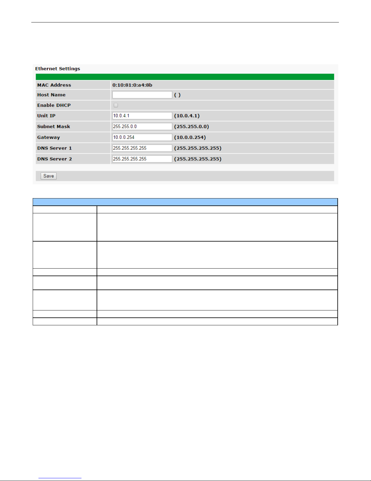
Ethernet8.3
Ethernet Settings
MAC Address
Hardware address of the NetGuardian. (Not editable - For reference only.)
Host Name
Used only for web browsing. Example: If you don't want to remember this NetGuardian's
IP address, you can type i n a name is this field, such as NG16. Once you save and
reboot the unit, you can now browse to it locally by simply typing in "NG16" in the
address bar. (no "http://" needed).
Enable DHCP
Used to turn on Dynamic Host Connection Protocol. NOT recommended, because the
unit is assigned an IP address from your DHCP server. The IP you've already assigned
to the unit becomes inactive. Using DHCP means the unit will NOT operate in a T/Mon
environment.
Unit IP
IP address of the NetGuardian.
Subnet Mask
A road sign to the NetGuardian, telling it wheth er your packets should stay on your local
network or be forwarded somewhere else on a wide-area network.
Gateway
An important parameter if you are connected to a wide-area network. It tells the
NetGuardian which machine is the gateway out of your local network. Set to
255.255.255.255 if not using. Contact your network administrator for this info.
DNS Server 1
Primary IP address of the domain name server. Set to 255.255.255.255 if not using.
DNS Server 2
Secondary IP address of the domain name server. Set to 255.255.255.255 is not using.
The Provisioning > Ethernet menu allows you to define and configure Ethernet settings.
The Provisioning > Ethernet menu
24
Note: DNS Server settings are required if a hostname is being used for ping targets.
Page 30
25
Notification Settings
ID
The notification's ID number.
Notify On
Specifies when the notification is sent. Possible values: (Disabled, Alarm, Clear,
Both)
Type
The type of notification. Possible values: (Email, SNMP)
Details
Some details about the notification.
If type is Email, it will show:
Host name or IP address and port number of SMTP server, recipient email address.
If type is SNMP, it will show:
Host name or IP address and port number of TRAP server.
Edit
Open the Edit page for a particular notification.
Test
Send a test notification.
Notifications8.4
The Provisioning > Notifications screen lists any notifications you may have configured, such as an Email or
SNMP. They can be sent when an alarm is raised and/or when an alarm is cleared. You can also test the
notifications you have created. Click Edit to edit an existing notification or create a new notification. Click Test to
send out a test notification.
The Notifications screen
Page 31
8.4.1 Edit
Edit Notification Settings
Status
Choose when to send a notification:
· Do not notify
· Notify on Alarm
· Notify on Clear
· Notify on Alarm and Clear
Type
Specifies when the notification is sent. Possible values: (Disabled, Alarm, Clear,
Both)
The Provisioning > Notifications > Edit screen allows you to set when and how you want to be notified about an
alarm.
The Edit Notification screen
26
Page 32
27
Email Notification Settings
SMTP Server IP or Host
Name
The IP address of your email server.
Port Number
The port used by your email server to receive emails, usually set to 25.
Use SSL
Check this box to use SSL encryption. Currently this feature has been tested w ith
Gmail. To send with Gmail SMTP server, do the following:
· SMTP Server IP or Host Name should be set to "smtp.gmail.com"
· Port number must be set to 465.
· SMTP authentication radio button must be selected.
· User name and password (below under "How to Authenticate") are the user name
and password for the Gmail account in use.
"From" E-mail Address
Displays the email address (defined in the Edit menu > System) that the Site Diale r
G3 will send emails from. Not editable from this screen.
"To" E-mail Address
The email address of the person responsible for this Site Dialer G3, who will receive
email alarm notifications.
Authentication
The authentication method. Possible values:
· No authentication
· POP before SMTP authentication
· SMTP authentication
POP Server IP or Host
Name
The IP address or host name of the POP server in charge of authentication.
Disabled if no authentication is selected.
POP Port
The port used by your POP server. Disabled if no authentication is selected.
User Name
User name for the email account being used. Disabled if no authentication is
selected.
Password
Password for the email account being used. Disabled if no authentication is
selected.
Confirm Password
Password for the email account being used again. Disabled if no authentication is
selected.
8.4.2 Email
The Email Notification screen allows you to configure an email notification.
The Email Notification screen
Page 33
8.4.3 SNMP
SNMP Notification Settings
SNMP Trap Server IP
The SNMP trap manager's IP address.
Trap Port No.
The SNMP port (UDP port) set by the SNMP trap manager to receive traps, usually
set to 162.
Trap Community
Community name for SNMP TRAP requests.
Trap Type
Indicate whether you w ould like to send SNMP v1, v2c, or v3 traps.
SNMPv3 User
Select the user. User is configured in the SNMP menu.
Notification Schedule Settings
Days of the week
From either Schedule 1 or 2, check which days you want to receive n otifications.
Any Time
Select this is if you want to receive al arm notifications at any time for the day(s)
you've selected.
Notification Time
Tells the unit to only send notifications during certain hours on the day(s) you've
selected.
The SNMP Notification screen appears when you choose SNMP as the Notification Type on the Provisioning >
Notifications > Edit screen and click Save and Next.
The SNMP Notification screen
28
8.4.4 Schedule
The Notification Schedule screen allows you to specify which days and times the notification should
be enabled. The selected notification is indicated at the top of the screen by its Notification ID.
The Notification Schedule screen
Page 34
29
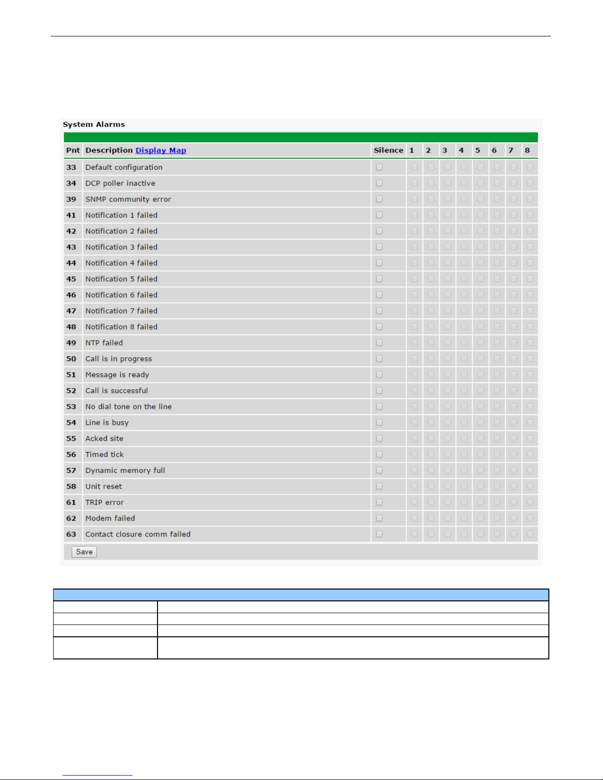
System Alarm Settings
Pnt (Point)
The system alarm point number.
Description
Non-editable description for this System (housekeeping) Alarm.
Silence
Check this box to choose to silence this alarm.
Notification Devices
Check which notification device(s), 1 through 8, you want to send alarm notifications for
that alarm point.
System Alarms8.5
The Provisioning > System Alarms screen shows all the system alarm conditions the device keeps
track of.
The System Alarms screen
Page 35
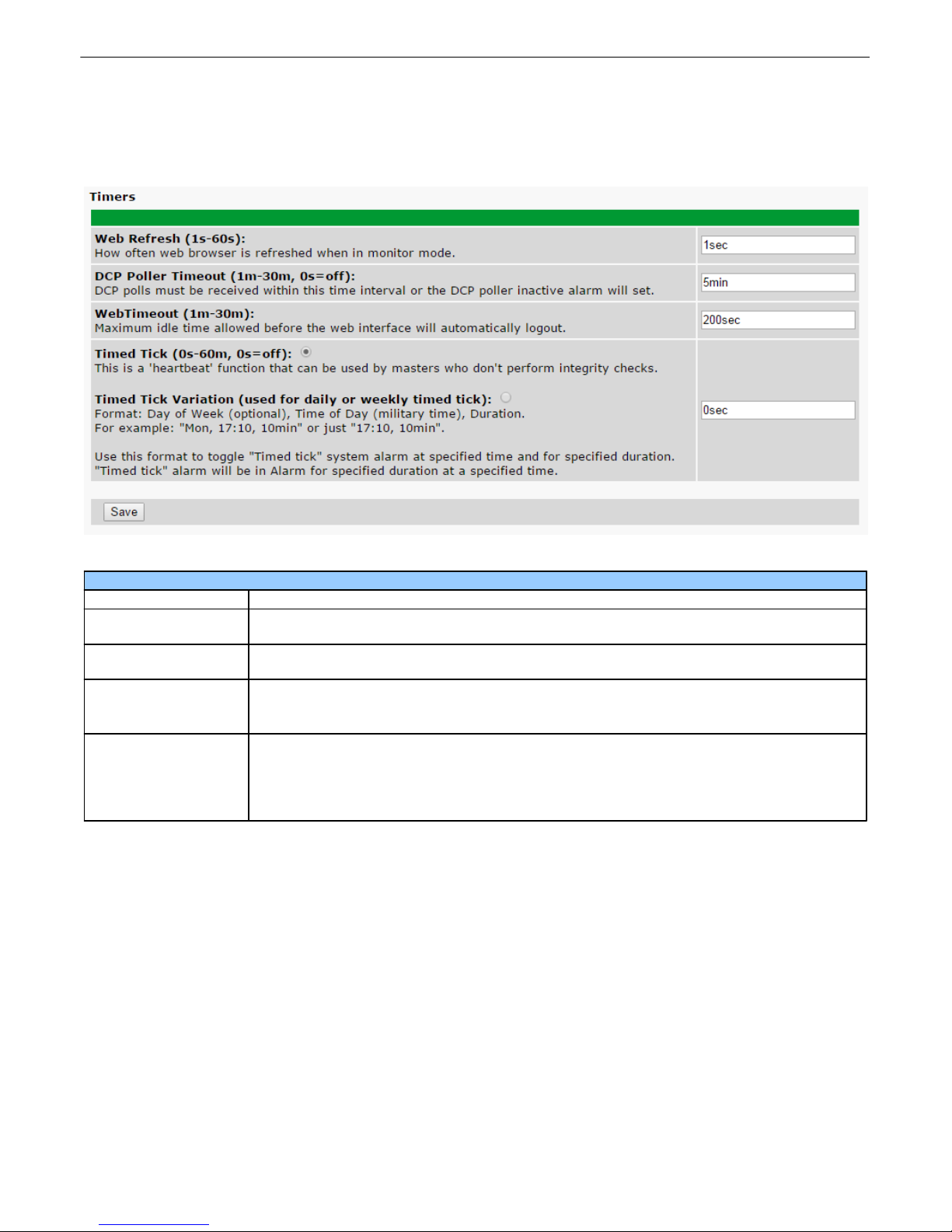
Timers8.6
Timer Settings
Web Refresh
How often web browser is refreshed when in monitor mode. Range: (1s-60s)
DCP Poller Timeout
DCP polls must be received within this time interval or the DCP poller inactive alarm will
set. Range: (1m-30m, 0s=off)
Web Timeout
Maximum idle time allowed before the web interface will automatically logout. Range:
(1m-30m)
Timed Tick
This is a 'heartbeat' function that can be used by masters who don't perform integrity
checks. Range: (0s-60m, 0s=off)
Timed Tick Variation
Used for daily or weekly timed tick. Use this format to toggle "Timed tick" system alarm
at specified time and for specified duration. "Timed tick" alarm will be in Alarm for
specified duration at a specified time.
Format: Day of Week (optional), Time of Day (military time), Duration.
For example: "Mon, 17:10, 10min" or just "17:10, 10min".
The Provisioning > Timers screen allows you to configure the web refresh rate, DCP poller timeout,
Web Timeout timeout, and timed tick s.
30
The Timers screen
Page 36
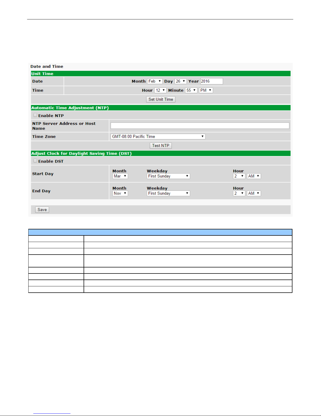
31
Date and Time Settings
Date
The current date.
Time
The current time.
Enable NTP
Check to enable automatic time adjustment with Network Time Protocol.
NTP Server Address
or Host Name
The NTP address or host name from where you want the unit to retrieve the t ime from.
Time Zone
The time zone the unit is located in.
Enable DST
Check to enable Daylight Savings Time acknowledgement on the unit.
Start Day
The date and time of the beginning of Daylight Savings Time.
End Day
The date and time of the end of Daylight Savings Time.
Date and Time8.7
The Provisioning > Date and Time screen allows you to set time and date on the unit, configure
automatic time adjustment, and adjust the clock for Daylight Savings Time.
The Date and Time screen
Page 37
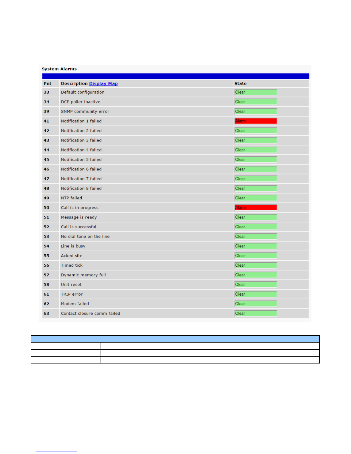
8.7.1 System Alarms
System Alarm Monitoring
ID
Alarm ID number.
Description
User-definable description for the discrete alarm point.
State
The current state of the alarm. (Clear or Alarm)
This selection provides the status of the system alarms by indicating if an alarm has been triggered. Under the
State column, the status will appear in red if an alarm has been activated. The status will be display ed in green
when the alarm condition is not present.
32
Click on Alarms in the Monitor menu to see if any base alarms have been triggered.
Monitoring Menu9
The Site Dialer G3 offers monitoring through the convenience of the Web Browser. Read the next topics to dive
into functions in the Monitoring menu.
Page 38
33
Test Call9.1
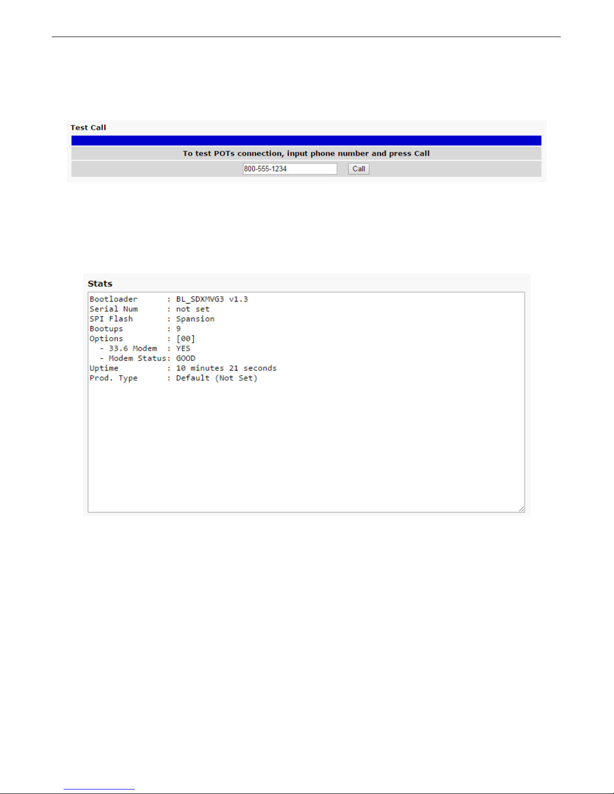
This selection provides a way to make a test call through a Plain Old Telephone Service (POTS)
connection. Just input the phone number you'd like to dial and press Call.
The Test Call screen
Stats9.2
This view shows various stats about the device, such as bootloader version, serial number, number of
bootups, current uptime, and more.
The Stats screen
Page 39
Device Access Menu10
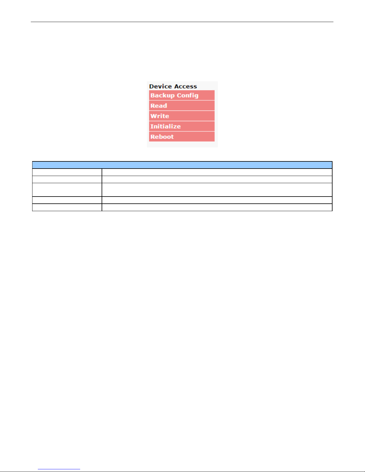
Device Access
Backup Config
Backs up the units configuration settings.
Read
Reads a configuration file from the unit.
Write
Commits all changes made in the web interface to the Site Dialer G3's non-volatile
memory.
Initialize
Sets the unit's configuration to factory default values.
Reboot
Reboots the Site Dialer G3.
The Device Access options, listed in pink on the left side of the web int erface, provide options for generating
reports, updating the Site Dialer G3's firmware, and rebooting the unit. Click any of the options under Device
Access to perform the desired action.
The control menu is located in the bottom left of the web interface
34
Page 40
35
Reference Section11
Updating Site Dialer G3 Firmware11.1
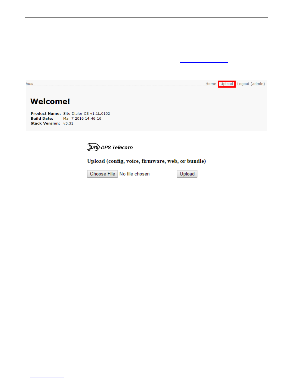
1. Open an Internet browser and navigate to the Site Dialer G3 at http://192.168.1.100.
2. Login with the default username of "admin" and password "dpstelecom"
3. Click Upload, located on the top right of the page.
4. Click Choose File and select a file to upload to the device.
5. Click Upload and the file will be transferred over.
Page 41
Updating T/Mon Software11.2
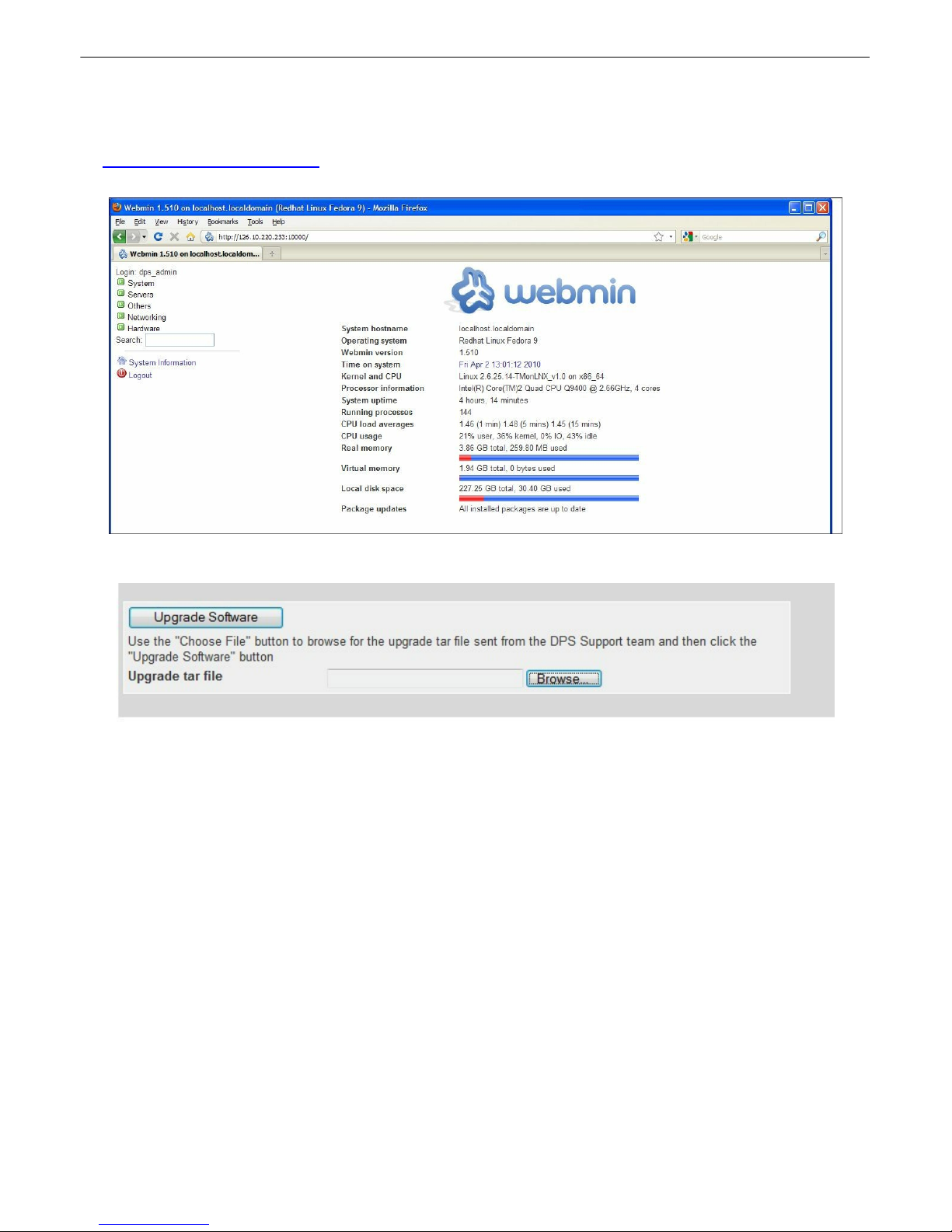
1. Open an Internet browser and navigate to the T/Mon at port 10000 (e.g.
http://192.168.1.100:10000).
2. Login with the default username of "dps_admin" and password "dpstelecom"
36
3. Select Others then Custom Commands.
4. Under the Upgrade Software section, select Browse to select the .tar file sent to you by DPS.
5. After Selecting the .tar file, select OK then select Upgrade Software.
Page 42

37
Points
Alarm Point
Description
Solution
33
Default configuration
Communication with Network Time Server has
failed.
Try pinging the Network Time Server’s IP Address as
it is configured. If the ping test is successful, then
check the port setting and verify the port is not being
blocked on your network.
34
DCP poller inactive
The Site Dialer is configured to listen for DCP polls
but has not received a poll in over 5 minutes.
Check if unit can ping T/Mon or disable if not in use.
39
SNMP community
error
Community string does not match your SNMP
master's community string.
Verify both community strings to make sure they
match.
41
Notification 1 failed
A notification 1 event, such as a page or email, was
unsuccessful.
Use RPT filter debug to help diagnose notification
problems.
42
Notification 2 failed
A notification 2 event, such as a page or email, was
unsuccessful.
Use RPT filter debug to help diagnose notification
problems.
43
Notification 3 failed
A notification 3 event, such as a page or email, was
unsuccessful.
Use RPT filter debug to help diagnose notification
problems.
44
Notification 4 failed
A notification 4 event, such as a page or email, was
unsuccessful.
Use RPT filter debug to help diagnose notification
problems.
45
Notification 5 failed
A notification 5 event, such as a page or email, was
unsuccessful.
Use RPT filter debug to help diagnose notification
problems.
46
Notification 6 failed
A notification 6 event, such as a page or email, was
unsuccessful.
Use RPT filter debug to help diagnose notification
problems.
47
Notification 7 failed
A notification 7 event, such as a page or email, was
unsuccessful.
Use RPT filter debug to help diagnose notification
problems.
48
Notification 8 failed
A notification 8 event, such as a page or email, was
unsuccessful.
Use RPT filter debug to help diagnose notification
problems.
49
NTP Failed
Communication with Network Time Server has
failed.
Try pinging the Network Time Server’s IP Address as
it is configured. If the ping test is successful, then
check the port setting and verify the port is not being
blocked on your network.
50
Call is in progress
Notifies T/Mon that a call is in progress and to wait
before sending next notification.
Will be automatically cleared once call has been
completed.
51
Message is ready
Message has been received from T/Mon and is
ready to be sent.
Will be automatically cleared by T/Mon once call is
complete.
52
Call is successful
Notifies T/Mon that call has completed successfully.
Will be automatically cleared by T/Mon once another
call is attempted.
53
No dial tone on the
line
During dial-out attempt, the unit did not detect a dial
tone.
Check the integrity of the phone line and cable.
54
Line is busy
During dial-out attempt, the unit detected a busy
signal.
Check the integrity of the phone line and cable.
55
Acked site
Notifies T/Mon to acknowledge an alarm.
Will be automatically cleared by T/Mon once another
call is attempted.
56
Timed Tick
Toggles state at constant rate as configured by the
Timed Tick timer variable. Useful in testing integrity
of SNMP trap alarm reporting.
To turn the feature off, set the Timed Tick timer to 0.
57
Dynamic memory
full
Not expected to occur.
Call DPS Tech Support (559) 454-1600
58
Unit reset
Unit has rebooted.
If unintentional, call DPS Tech Support: (559) 454-
1600.61TRIP error
Not expected to occur.
Call DPS Tech Support (559) 454-1600
62
Modem failed
The modem component to the Site Dialer has
stopped responding.
Check if modem is properly placed in socket. Contact
DPS Tech Support (559) 454-1600
63
Contact closure
comm failed
Not expected to occur.
Call DPS Tech Support (559) 454-1600
System Alarms Map11.3
Page 43

Technical Support12
DPS Telecom products are backed by our courteous, friendly Technical Support representatives, who
will give you the best in fast and accurate customer service. To help us help you better, please take the
following steps before calling Technical Support:
1. Check the DPS Telecom website.
You will find answers to many common questions on the DPS Telecom website, at http://
www.dpstele.com/support/. Look here first for a fast solution to your problem.
2. Prepare relevant information.
Having important information about your DPS Telecom product in hand when you call will greatly
reduce the time it takes to answer your questions. If you do not have all of the information when you
call, our Technical Support representatives can assist you in gathering it. Please write the information
down for easy access. Please have your user manual and hardware serial number ready.
3. Have access to troubled equipment.
Please be at or near your equipment when you call DPS Telecom Technical Support. This will help
us solve your problem more efficiently.
38
4. Call during Customer Support hours.
Customer support hours are Monday through Friday, from 7 A.M. to 6 P.M., Pacific time. The DPS
Telecom Technical Support phone number is (559) 454-1600.
Emergency Assistance: Emergency assistance is available 24 hours a day, 7 days a week. For
emergency assistance after hours, allow the phone to ring until it is answered with a paging message.
You will be asked to enter your phone number. An on-call technical support representative will return
your call as soon as possible.
Page 44

39
T/Mon Gold and Platinum Plans13
T/Mon Gold & Platinum Plan Support Escalation Policy
(559) 454-1600 Phone
(559) 454-1688 Fax
[email protected] Email
When you call DPS for T/Mon LNX support under your T/Mon maintenance agreement, you'll receive the
following benefits:
1. If you call during normal DPS operating hours (7:00am to 6:00pm Pacific Standard Time), you will receive
priority tech support in front of all calls from users without a T/Mon Gold Plan. If you have an emergency
situation, your call will be prioritized to the top of the list (at uncommon times when there is a list).
2. If you call outside normal DPS operating hours with an emergency (ex. "System is Down"), you have access to
7x24x365 Tech Support. Follow the recorded voice instructions to alert the on-call technician. The on-call
technician will typ ically return your call within 15 minutes.
3. With your permission, DPS technicians can remotely access your T/Mon from DPS Headquarters (typically via
dialup) to facilitate diagnostics and instructions. You can follow along on your T/Mon screen as technicians
control your T/Mon.
4. If it is determined that DPS hardware is at fault, one of the following will occur at DPS' discretion:
· With client consent, DPS will, on a priority basis, expedite a replacement component for the client's
qualified staff to install.
· The client will ship the unit back to DPS for priority repair and return on a priority basis. When units are
received by DPS before 12:00pm, they are repai red, t ested, and shipped back to the client within one
business day, provided there are no extenuating circumstances.
· DPS will advance-replace the entire T/Mon unit. After receiving the new T/Mon, the client will ship the
failed unit to DPS. The unit will be repaired and shipped back to the client. Upon receiving the repaired
unit, the client will return the advance-replacement unit to DPS.
Extended Maintenance Agreement Benefits:
· Half-Price or Free Hardware Upgrades
T/Mon operates 7x24x365. That’s stressful for any hardware. Plus, the DPS engineers are constantly
improving the platform. That’s 2 big reasons why you should update your T/Mon hardware regularly. T/
Mon Maintenance Agreements make it easy to get the equivalent of a brand new monitoring system every
3-5 years. You’ll stay well ahead of the mortality curve, and you’ll never get stuck using ancient
technology.
Participate in our 50%-off upgrade program at the end of your third consecutive year as a Gold Plan
member, OR Participate in our free upgrade program at the end of your fifth consecutive year as a
Platinum Plan member. We’ll send you a brand new T/Mon. Just send us back the old one.
· Software upgrades
Includes major release(s), plus updates throughout the life of your Gold/Platinum Plan. These major
releases are not small. They incorporate user feedback, industry best practices evolution, entirely new
capabilities, as well as the occasional code correction.
· 4-Day Factory Training course
Hosted at our corporate headquarters (up to 3 members from your team can attend per session - multiple
sessions per year).
· Spares and standby purchase discount
Backup units are essential for disaster recovery. With a Gold/Platinum Plan, you’ll get discount prices on
purchasing spare parts and standby units.
Page 45

End User License Agreement14
All Software and firmware used in, for, or in connection with the Product, parts, subsystems, or derivatives thereof,
in whatever form, including, without limitation, source code, object code and microcode, including any computer
programs and any documentation relating to or describing such Software is furnished to the End User only under a
non-exclusive perpetual license solely for End User's use with the Product.
The Software may not be copied or modified, in whole or in part, for any purpose wha t soever. The Software may
not be reverse engineered, compiled, or disassembled. No title to or ownership of the Software or any of its parts
is transferred to the End User. Title to all patents, copyrights, trade secrets, and any other applicable rights shall
remain with the DPS Telecom.
DPS Telecom's warranty and limitation on its liability for the Software is as described in the warranty information
provided to End User in the Product Manual.
End User shall indemnify DPS Telecom and hold it harmless for and against any and all claims, damages, losses,
costs, expenses, obligations, liabilities, fees and costs and all amounts paid in settlement of any claim, action or
suit which may be asserted against DPS Telecom which arise out of or are related to the non-fulfillment of any
covenant or obligation of End User in connection with this Agreement.
This Agreement shall be construed and enforced in accordance with the laws of the State of California, without
regard to choice of law principles and excluding the provisions of the UN Convention on Contracts for the
International Sale of Goods. Any dispute arising out of the Agreement shall be commenced and maintained only in
Fresno County, California. In the event suit is brought or an atto rney is retained by any party to this Agreement to
seek interpretation or construction of any term or provision of this Agreement, to enforce the terms of this
Agreement, to collect any money due, or to obtain any money damages or equitable relief for breach, the
prevailing party shall be entitled to recover, in addition to any other available remedy, reimbursement for
reasonable attorneys' fees, court costs, costs of investigation, and other related expenses.
40
Page 46

41
Page 47

42
Page 48

“Dependable, Powerful Solutions
that allow users to monitor larger,
more complicated networks with a
smaller, less trained staff”
“Your Partne rs in Ne t w o rk Ala rm Management ”
www.dpstelecom.com
4955 E Yale • Fresno, CA 93727
559-454-1600 • 800-622-3314 • 559-454-1688 fax
 Loading...