

Page 1
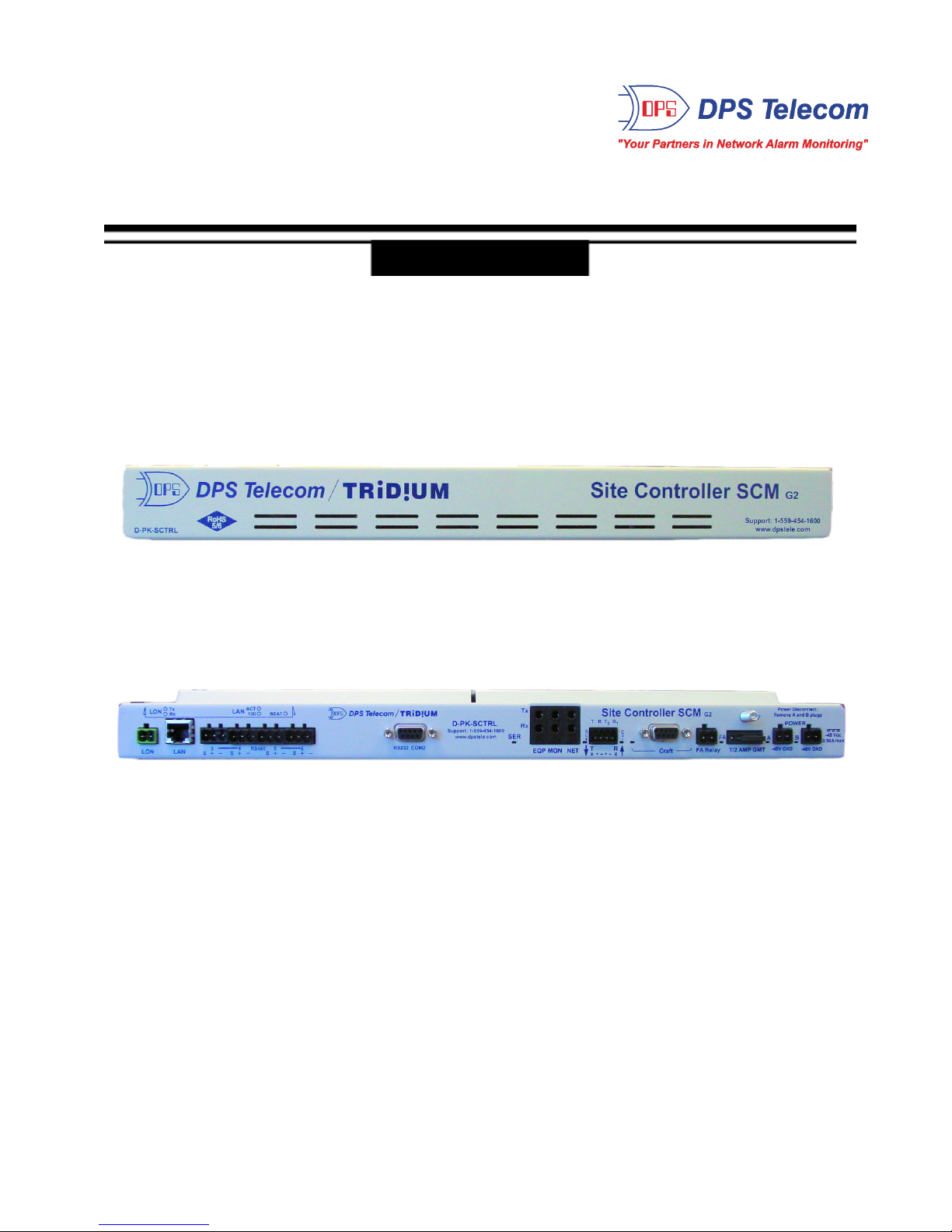
Site Controller SCM G2
USER MANUAL
Visit our website at www.dpstelecom.com for the latest PDF manual and FAQs.
April 9, 2007 D-OC-UM0074.9200
Firmware Version v1.0G
Page 2

Revision History
April 9, 2007
May 4, 2005
March 8, 2005
March 3, 2005
January 28, 2005
Site Controller SCM G2 User Manual (D-OC-UM0074.9200) released
Site Controller SCM G1 User Manual (D-OC-UM055.04100) released
Site Controller SCM G1 User Manual (D-OC-UM053.08200) released
Site Controller SCM G1 User Manual (D-OC-UM053.03100) released
Site Controller SCM G1 User Manual (D-OC-UM051.28100) released
This document contains proprietary information which is protected by copyright. All rights are reserved. No part of this
document may be photocopied without prior written consent of DPS Telecom.
All software and manuals are copyrighted by DPS Telecom. Said software and manuals may not be reproduced, copied,
transmitted or used to make a derivative work, by either mechanical, electronic or any other means in whole or in part,
without prior written consent from DPS Telecom, except as required by United States copyright laws.
© 2007 DPS Telecom
Notice
The material in this manual is for information purposes and is subject to change without notice. DPS Telecom shall not be
liable for errors contained herein or consequential damages in connection with the furnishing, performance, or use of this
manual.
Page 3

Contents
Visit our website at www.dpstelecom.com for the latest PDF manual and FAQs
Introduction1 1
Specifications2 1
Shipping List3 2
Installation4 3
Tools Needed4.1 3
Mounting4.2 3
Power Connection4.3 4
Network Connections4.4 5
Back Panel LEDs5 6
TTY Interface6 8
Terminal Interface6.1 9
Logon6.2 9
Settings and Timers6.3 10
Selecting Master and Slave Modes6.3.1 10
Configure Timers6.3.2 11
6.3.2.1 RTS Head Time 11
6.3.2.2 RTS Tail Time 11
6.3.2.3 Character Wait Time 11
6.3.2.4 Poll Wait Time 12
Status6.4 12
NVRAM6.5 13
Tune 202 Modem6.6 13
Updating Firmware7 14
LED Display7.1 16
Technical Support8 17
Page 4
1
Fig. 1.1.
The Site Controller SCM
The DPS Telecom Site Controller SCM mediates Modbus protocol traffic between Tridium JACE-545™ devices
(JACE). The Site Controller SCM converts the 9600 baud RS–232 JACE traffic to 1200 baud 202 for transport to
other Site Control Managers. Central to the Site Controller SCM design is an in-case integration of the Tridium
JACE-545™ device. In other words, the DPS Site Controller SCM and the JACE are inside a single chassis,
reducing the need for extra connectors and rack space.
Note:
the JACE-545 device is a trademark of Tridium, Inc.
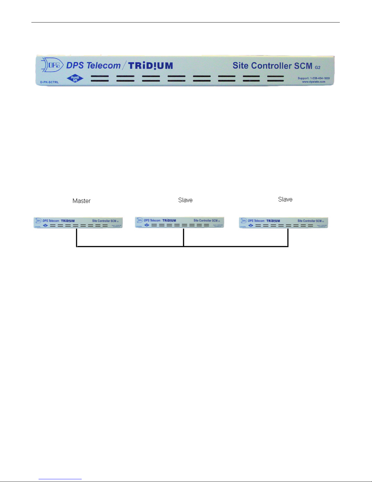
The Site Controller SCM has two modes: master and slave. One master Site Controller SCM connects the JACE
Modbus interrogator to the 202 service channel. A slave Site Controller SCM links a JACE Modbus responder to
the service channel. A single Site Controller SCM master unit polls multiple Site Controller SCM slave units.
Fig. 1.2.
Example Site Controller SCM Application
Dimensions:
1¾"H x 17"W x 12"D (4.45 cm x 43.18 cm x 30.48 cm)
Weight:
4 lbs. 3 oz. (1.9 kg)
Mounting:
19" or 23" rack
Power Input:
–48 VDC dual feed
Current Draw:
300mA
Fuse:
½ Amp GMT
Interfaces:
1 4-pin barrier 202 port
1 DB9 craft port
Operating Temperature:
32°–140° F (0°–60° C)
Operating Humidity:
0%–95% noncondensing
Introduction1
Specifications2
Page 5
2
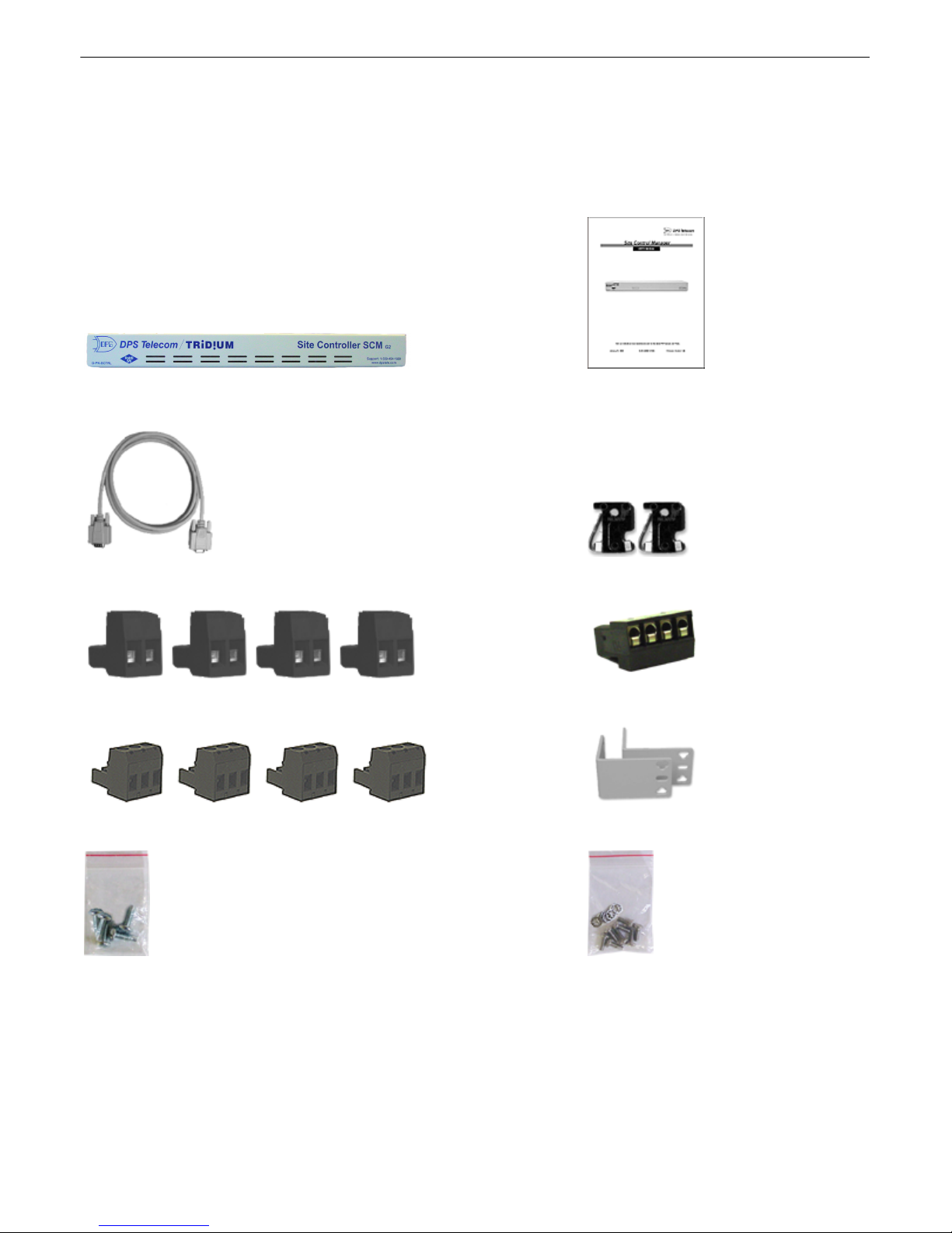
While unpacking the Site Controller SCM, please make sure that all of the following items are included. If some
parts are missing, or if you ever need to order new parts, please refer to the part numbers listed and call DPS
Telecom at
(800) 622-3314
.
Site Controller SCM
User Manual
D-PK-SCTRL-12000
D-OC-UM0074.9200
DB9M-DB9F Download Cable 6 ft.
Two ½-Amp GMT Fuse
Four Power/FA/LON Screw Lug Barrier Plugs
One 4-pin Barrier Plug
Four 3-pin Barrier Plugs
19"/23" Rack Ears
Four Rack Screws
Eight 3/8" Ear Screws
and Eight Lock Washers
Shipping List3
Page 6
3
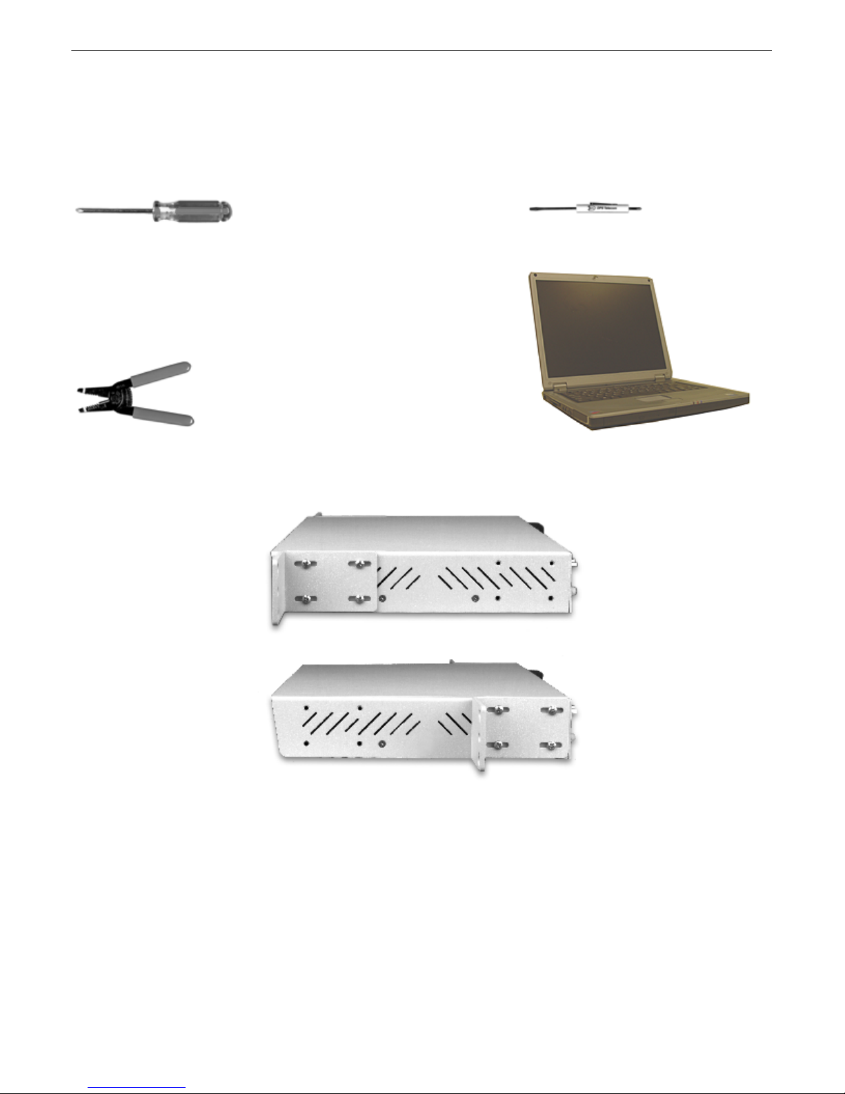
To install the Site Controller SCM, you'll need the following tools:
Phillips No. 2 Screwdriver
Small Standard No. 2 Screwdriver
Wire Strippers/Cutter
Computer with TTY Interface
Fig. 4.1.
The Site Controller SCM can be flush or rear-mounted
The Site Controller SCM can be mounted in a 23" rack, but other mount options maybe available. Attach the rack
ear in the flush-mount or rear-mount locations shown in Figure 4.1.
Installation4
Tools Needed4.1
Mounting4.2
Page 7
4
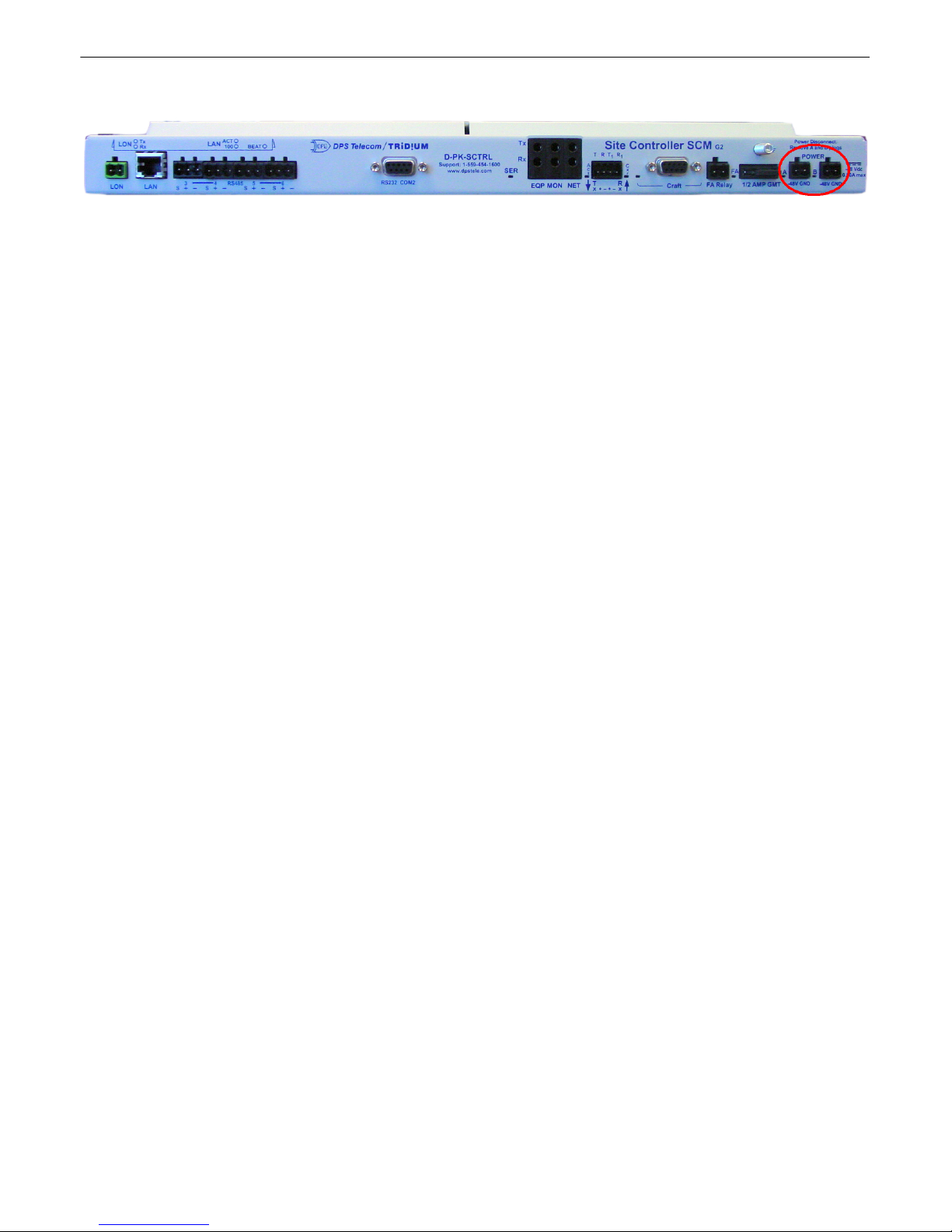
Fig. 4.2.
Power source connections
To connect the Site Controller SCM to a power source, follow these steps:
NOTE:
Do not apply –48V Power to the Site Controller SCM until all power Connections in Step 1
through Step 7 have been completed.
NOTE:
Use proper lug terminations on all power and frame ground connections to the Site Controller
SCM power input terminal strips.
NOTE:
The "A" and "B" power leads must be diversely run from the power input terminal strips to their
power source. One power lead must be routed on one side of the bay and the other routed on the
other side of the bay.
1.
Remove the fuse from the front panel of the Site Controller SCM and make sure that the power supply to the
unit is off.
2.
Remove the screw lug barrier plug from the front panel of the Site Controller SCM.
3.
Connect a –48 VDC line to the –48V terminal and a battery ground to the GND terminal of the screw lug.
Seat the barrier screws firmly, but be careful not to nick the bare wire. Repeat for power source B if you have
dual power inputs.
4.
Push the plug firmly back into its socket. Note that this connection is keyed and the plug must be properly
aligned within the socket.
5.
For earth/frame grounding, connect a copper wire with a ring terminal to the grounding post located on the
back panel of the Site Controller SCM. DPS Telecom recommends wire of at least 14 gauge. Place the ring
terminal between the two nuts and secure the nuts on the grounding post. Connect the other end of the wire to
an earth/frame ground.
6.
With the Site Controller SCM fuse still removed, turn on the power supply.
7.
Connect the black common lead of a voltmeter to the GND terminal and the red lead to the –48V terminal.
The voltmeter should read between –43 and –53 VDC. If the reading is outside this range, check your power
supply.
8.
Do not power the unit until all connections have been made.
9.
Insert the fuse to power the Site Controller SCM.
Power Connection4.3
Page 8
5
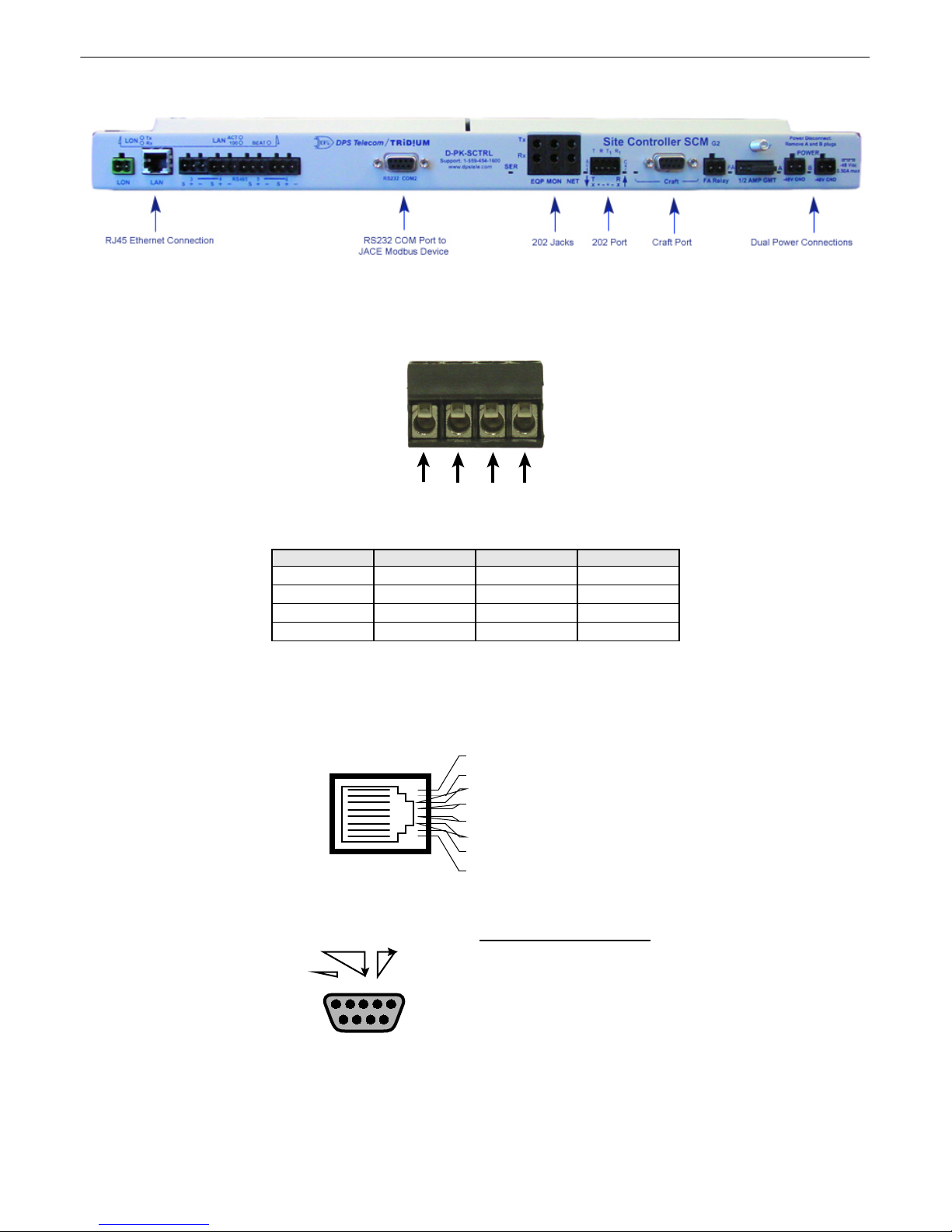
Fig. 4.3.
The back panel of the Site Controller SCM
Port 1 connects the Site Controller SCM to the 202 service channel. TX refers to transmission from the Site
Controller SCM, and RX refers to reception to the Site Controller SCM.
Fig. 4.4.
4-pin barrier
Pin
Signal
Label
Wire Color
1
TX+
T
Wht/Blu
2
TX-
R
Blu/Wht
3
RX+
T1 Wht/Org
4
RX-
R
1
Org/Wht
Table 4.A
Pinout descriptions
Fig. 4.5.
RJ45 pinout
Fig. 4.6.
Front panel DB9 craft port pinout
Network Connections4.4
RJ45 Ethernet Connection
DB9 RS-232
RX
GND
1
TX
12345
6789
3 4
2
8
7
6 Receive In– (RI–)
5
4
3 Receive In + (RI+)
2 Transmit Out– (TO–)
1 Transmit Out + (TO+)
Pin # Signal Description
1 Not connected
2 TX Transmit data
3 RX
4
5 GND Ground
6 Not connected
7
8
9 Not connected
Receive data
Not connected
Not connected
Not connected
Page 9
6
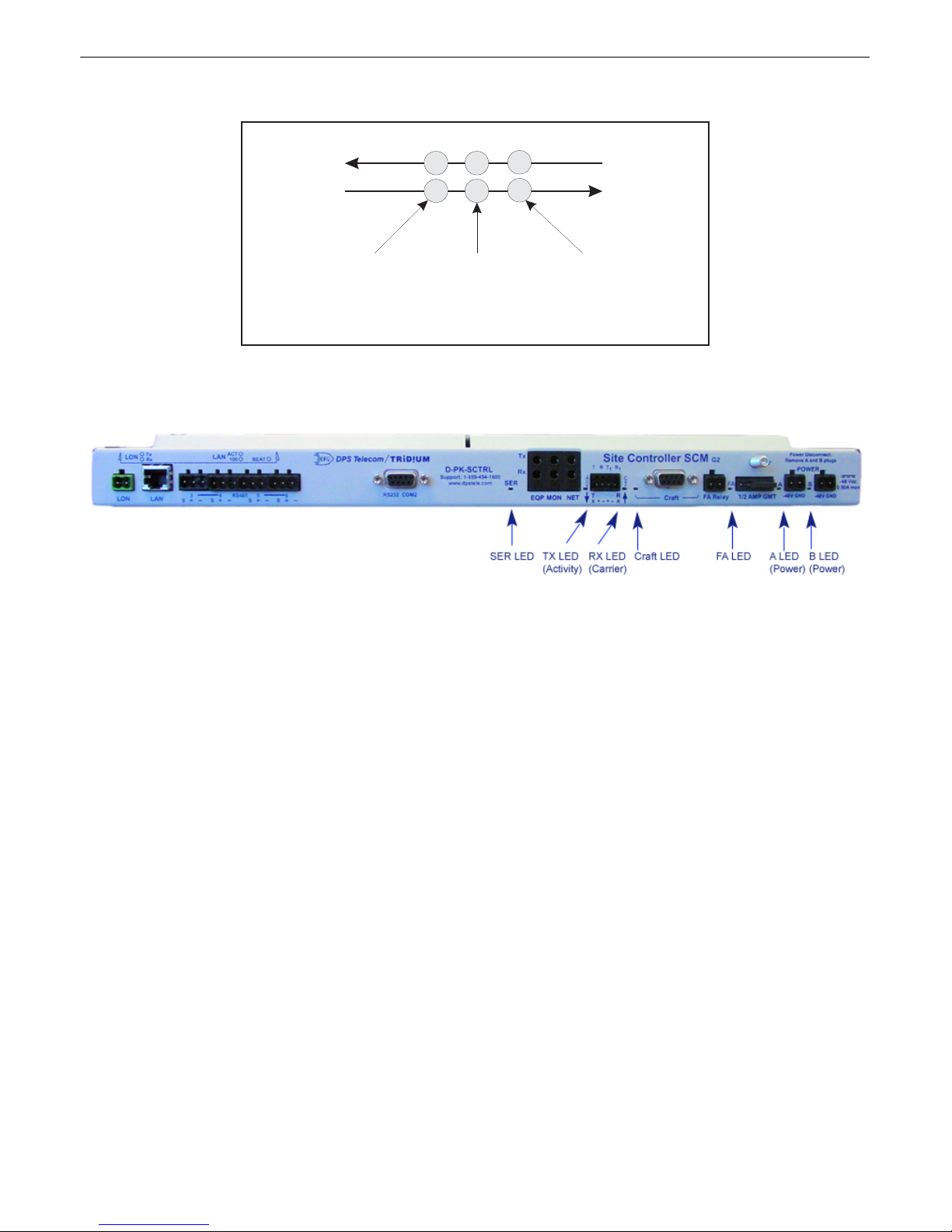
Bantam jacks are provided on the front panel for testing the VF interface — refer to Figure 4.3.
Fig. 4.7.
Front panel 202 jacks pinout
Fig. 5.1.
Front panel LED display
The four bicolor LEDs on the front panel of the Site Controller SCM provides visual feedback of communication
status.
Note:
see section 7.1 for LED display descriptions during firmware uploading.
The
CRAFT LED
displays communication on the craft utility port — see Section 5 (TTY Interface). The
CRAFT LED
will BLINK GREEN when the Site Controller SCM is TRANSMITTING data, and BLINK RED
when the Site Controller SCM is RECEIVING data.
The
SER LED
displays serial communication to and from the JACE device. The
SER LED
will BLINK GREEN
when the Site Controller SCM is TRANSMITTING data to the JACE device, and BLINK RED when the Site
Controller SCM is RECEIVING data from the JACE device.
The
C (Carrier) LED
displays 202 carrier status. The
C LED
will show GREEN when carrier is seen from
another Site Controller SCM.
Note:
The Site Controller SCM will only receive data on the 202 channel when carrier is seen from another Site
Controller SCM.
The
A (Activity) LED
displays communication status of the 202 service channel. The
A (Activity) LED
will
BLINK GREEN when the Site Controller SCM is TRANSMITTING data from the service channel, and BLINK
RED when the Site Controller SCM is RECEIVING data from the service channel.
The
FA LED
displays the status of the fuse. The
FA LED
will show SOLID RED when the fuse has failed.
The
A
and
B (Power) LEDs
displays the status of the power polarity. The
A
and
B (Power) LEDs
will show
SOLID GREEN when the power polarity is correct, and SOLID RED when the power polarity is backwards.
To
Transmission
Facility
Plug in here
to connect to line
(disconnects Site
Controller SCM)
LINE MON
TX
RX
Plug in
here to
monitor
signal
(non-intrusive)
EQP
To Site
Controller
SCM
Plug in here
to cnnnect to
the KDA 864-E2
(disconnects line)
Back Panel LEDs5
Page 10

7
Refer to Table 5.A for front panel LED status display explanations.
LED
NAME
STATE
MEANING
Blink Red
Receiving data on the Craft serial port.
1 CRAFT
Blink Green
Transmitting data on the Craft serial port.
Blink Red
Receiving data on the JACE serial port.
2 SER
Blink Green
Transmitting data on the JACE serial port.
Off
No DCD seen from another Site Control Manager.
3
C
(Carrier)
Green
Indicates DCD is seen from another Site Control Manager.
Blink Red
Receiving data on 202 service channel.
4
A
(Activity)
Blink Green
Transmitting data on 202 service channel.
5
FA
Solid Red
Fuse has failed.
Solid Green
Power Polarity is correct.
6
A and B
(Power)
Solid Red
Power Polarity is backwards.
Table. 5.A.
Front panel LED status chart
Page 11
8
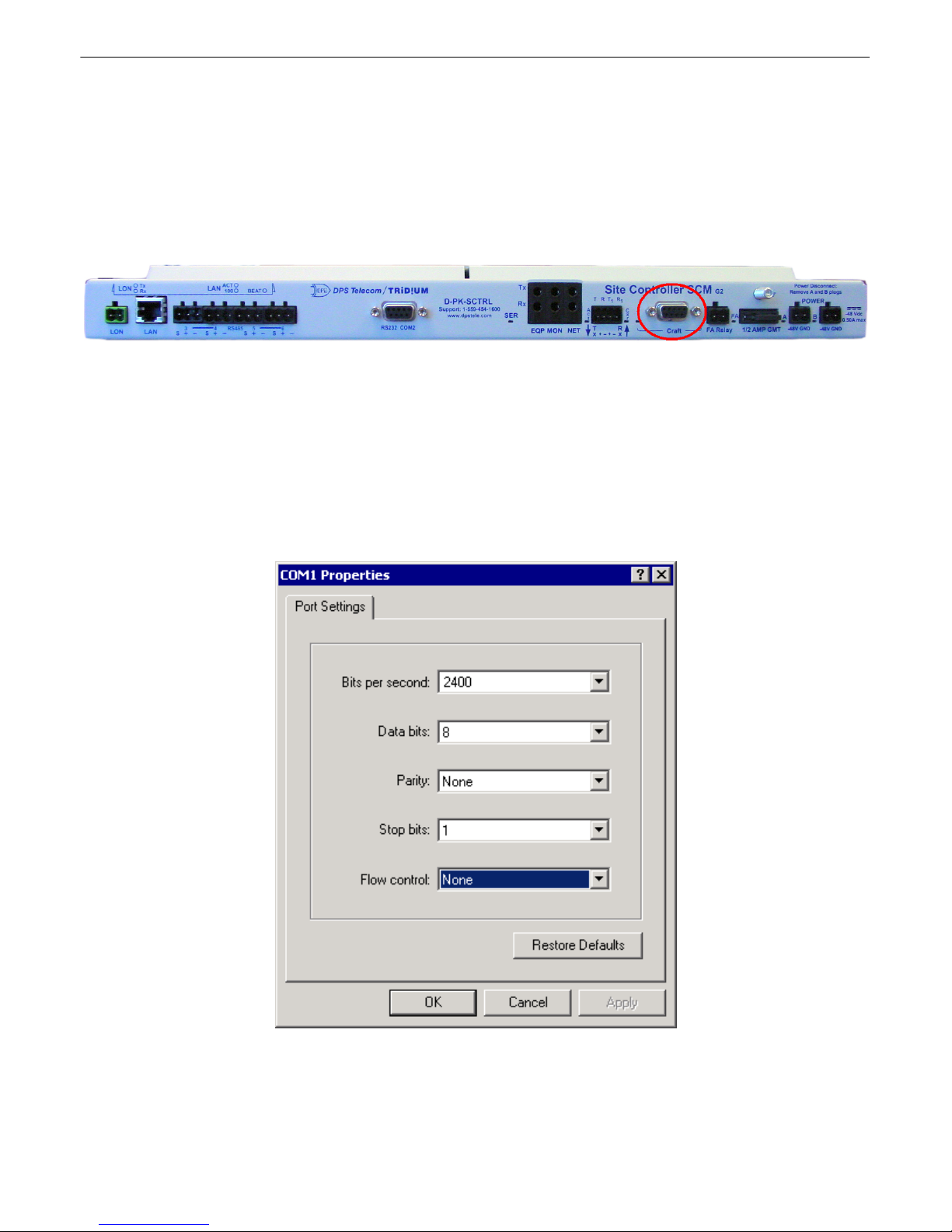
The Site Controller SCM has a simple TTY interface for provisioning and monitoring the device. Use the
following steps to start a TTY Interface session with your Site Controller SCM:
1.
Connect a DB9 download cable from the Site Controller SCM's front panel craft port to a PC — see Figure
6.1.
Fig. 6.1.
The Site Controller SCM craft port
2.
You will need to use terminal emulation software, such as Windows™ HyperTerminal. To open
HyperTerminal, start from your Windows™ Start menu and go to Programs > Accessories >
Communications > HyperTerminal.
3.
The Connection Description prompt will appear. Enter a description.
4.
The Connect To prompt will appear. In the Connect Using field, select COM 1 from the drop-down menu.
5.
The COM1 Properties Settings prompt will appear — see Figure 6.2. Your settings should be:
2400 baud, 8
bits, 1 stop bits, and None (Flow Control)
.6.Press C to continue to the Site Controller SCM main menu interface.
Fig. 6.2.
Port settings to connect to the Site Controller SCM
TTY Interface6
Page 12
9
Fig. 6.3.
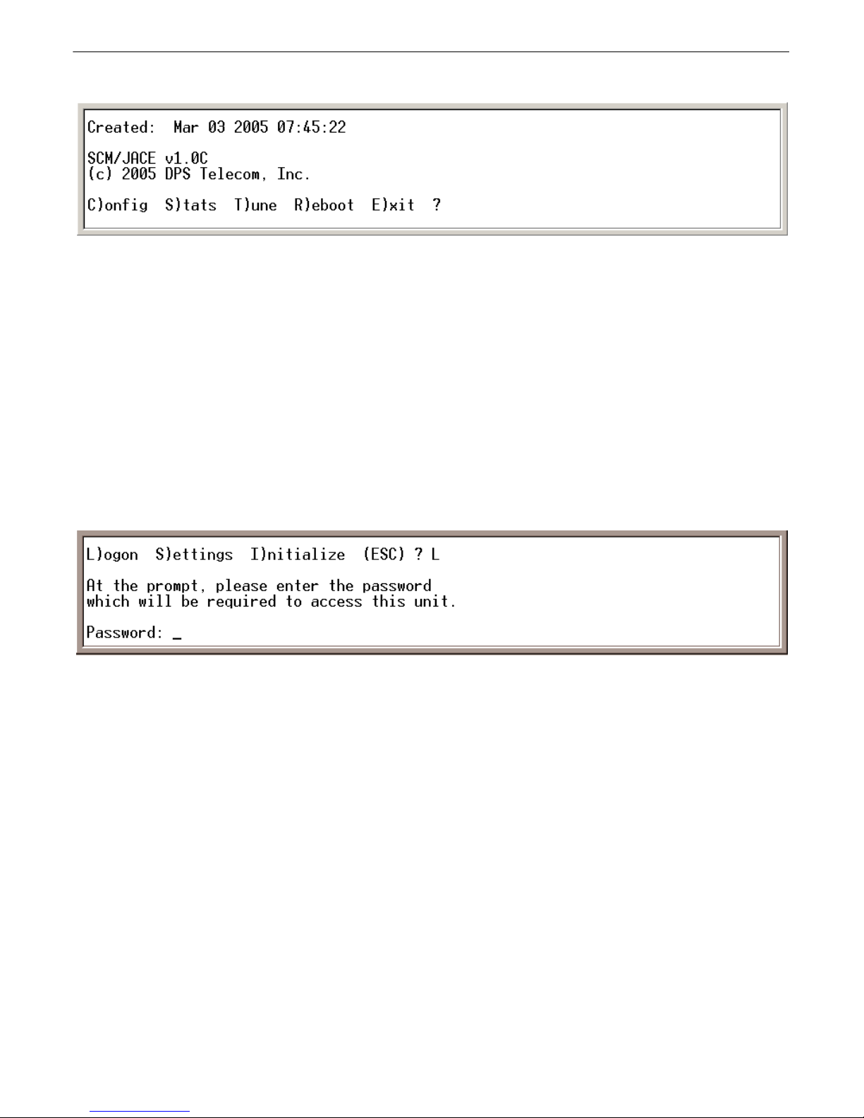
Site Controller SCM configuration main menu
To enter the main menu, type the Site Controller SCM's factory default password. The factory default password
is "dpstelecom" all in lower case. You can change the password later in the C)onfig > L)ogon menu — see
Section 6.2. Type the password and press Enter.
Note:
the password is case sensitive.
After entering the password, you will see the Site Controller SCM configuration main menu, as shown in Figure
6.3. To choose a command, press the key for the letter before or within the parenthesis. For example, to select the
C)onfig menu from the main menu, press C. To E)xit the terminal interface, press E. To quit a menu, press Esc
and you will return to the previous menu.
Configuration changes take effect automatically whenever changes are made to a setting. Saved settings are
stored in NVRAM, which means the settings will survive even after a power loss to the unit or site — see section
6.5 (NVRAM).
Fig. 6.4.
Editing the password
Press C (Config) from the main menu, then press L (Logon) to edit the password. At the prompt, enter your new
password — see Figure 6.4.
Note:
the password is case sensitive.
If you choose to change the password, you will be prompted to type the new password once to enter and a second
time to confirm.
Terminal Interface6.1
Logon6.2
Page 13
Settings and Timers6.3
Fig. 6.5.
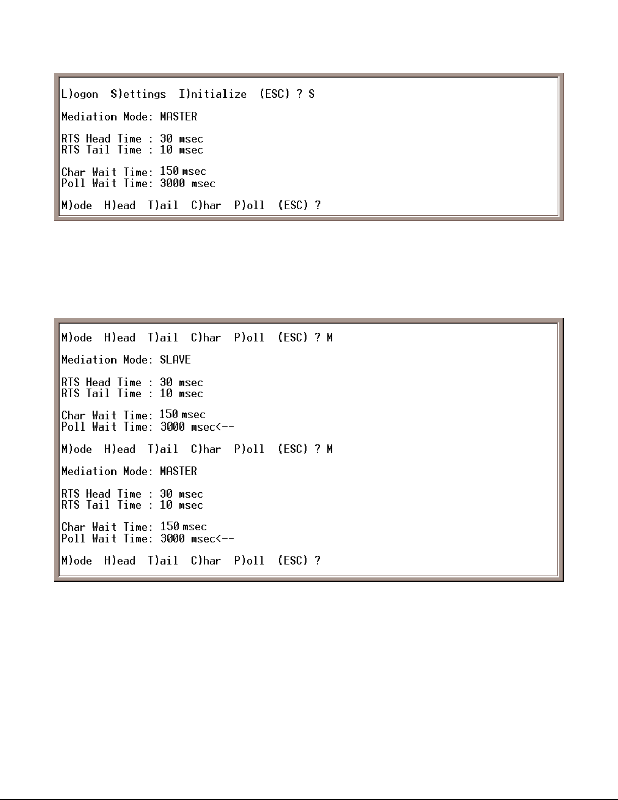
The Settings menu commands
The S)ettings menu contains commands for selecting Master and Slave modes, editing the RTS head and tail
times, the poll timeout interval, and the character timeout interval. To configure your settings, press C (Config) in
the main menu, then press S (Settings).
Fig. 6.6.
Select Master mode from Settings menu
Use the following steps to select Master or Slave mode:
1.
At the main menu press C (Config).
2.
Press S (Settings) for the S)ettings menu.
3.
Press M (Mode) to select Master or Slave mode — see Figure 6.6.
Note:
Slave Mode is the default setting.
6.3.1 Selecting Master and Slave Modes
10
Page 14
11
Fig. 6.7.
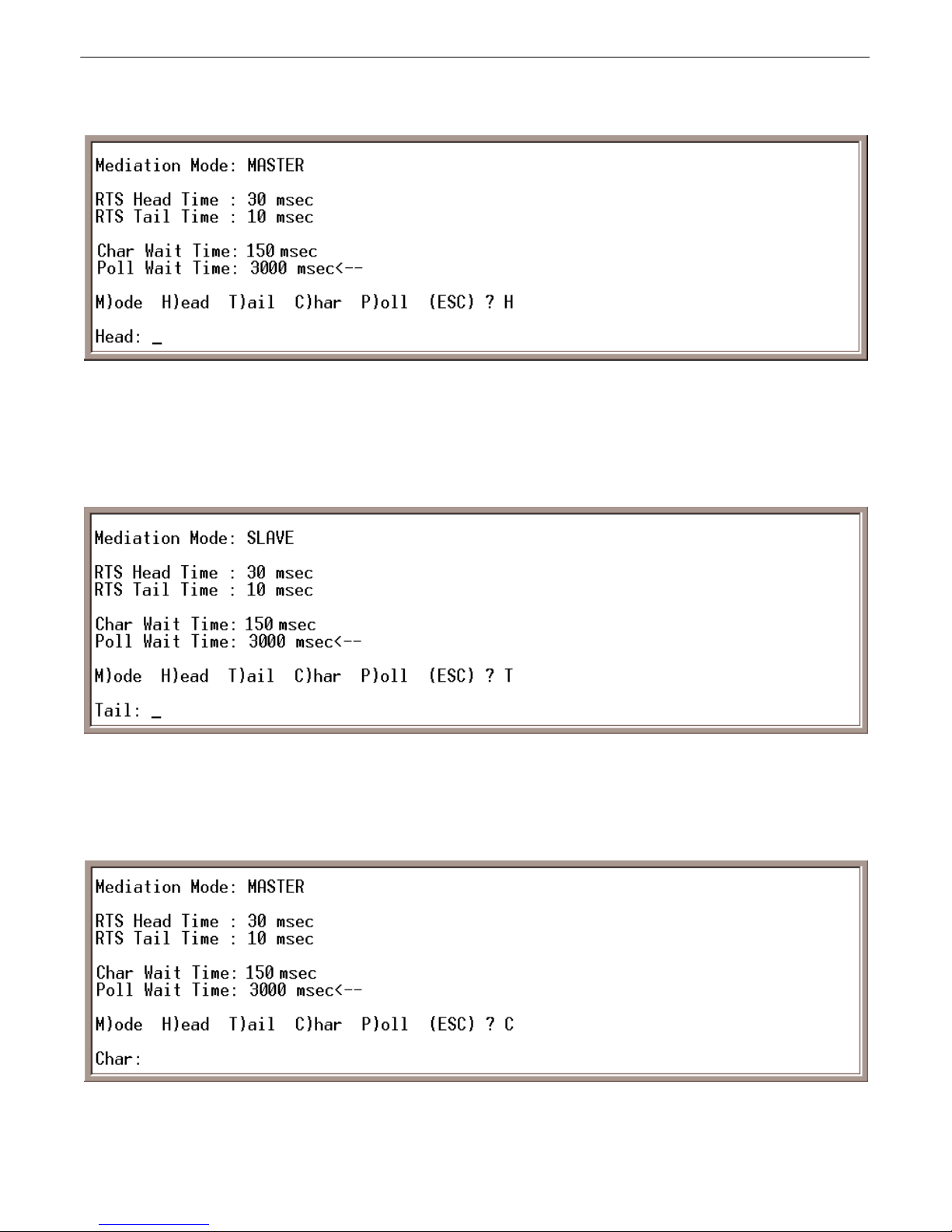
Press H in the C)onfig > S)ettings menu to configure RTS Head time
The C)onfig > S)ettings > H)ead command opens options for setting the RTS Head time (how long the Site
Controller SCM carrier is on before transmitting data). The default value time is 30 msec (milliseconds). RTS
head time range is 0-255 msec.
Fig. 6.8.
Press T in the C)onfig > S)ettings menu to configure RTS Tail time
The C)onfig > S)ettings > T)ail command opens options for setting the RTS tail time (how long the carrier is on
after transmitting data). The default value time is 10 msec. RTS tail time range is 0-255 msec.
Fig. 6.9.
Press C in the C)onfig > S)ettings menu to configure Character Wait Time
The C)onfig > S)ettings > C)har (Character Wait Time) command sets the character timeout timer. The character
6.3.2 Configure Timers
6.3.2.1 RTS Head Time
6.3.2.2 RTS Tail Time
6.3.2.3 Character Wait Time
Page 15
timeout is the interval between characters in data transmission. Character timeout range is 0–255 msec. The
default setting is 150 msec.
6.3.2.4 Poll Wait Time
Fig. 6.10.
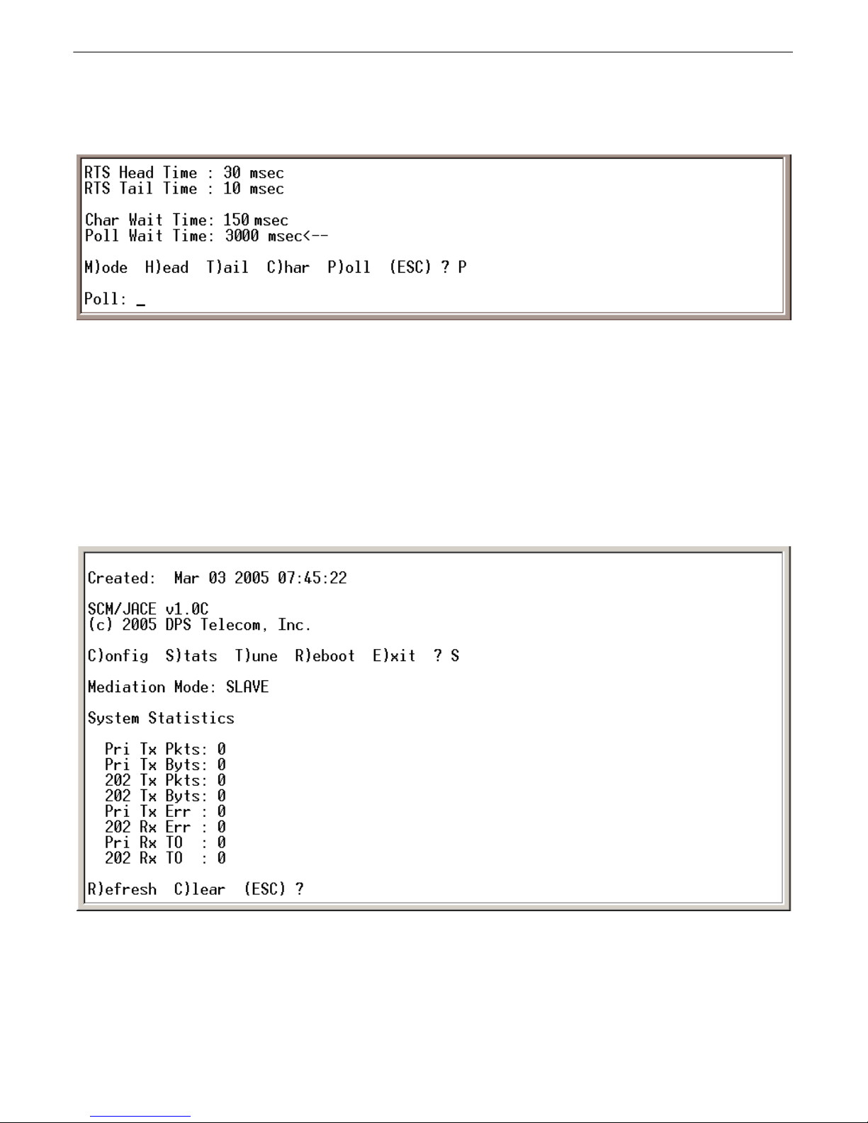
Press P in the C)onfig > S)ettings menu to configure Poll Wait Time
The C)onfig > S)ettings > P)oll command sets the poll timeout timer. The poll timeout is the time limit within
which the slave Site Controller SCM or JACE Modbus responder must respond to a poll before it is declared
failed. Range for poll timeout is 20–9999 msec. The default setting is 3000 msec.
The Poll Wait Time command works differently under Slave and Master modes. When the Site Controller SCM
is set to Slave mode, the timeout refers to communication between the Site Controller SCM and the JACE
Modbus responder. When the Site Controller SCM is set to Master mode, the timeout refers to communication
between the master Site Controller SCM and slave Site Control Managers.
Fig. 6.11.
Press S from the main menu to monitor the Site Controller SCM's stats
Monitor the number of packets transmitted and received by the Site Controller SCM by pressing S (Stats) from
the main menu — see Figure 6.11. At the prompt, press R to refresh the status page, press C to clear, or press Esc
to return to the previous menu.
12
Status6.4
Page 16
13
Fig. 6.12.
Set to factory default settings
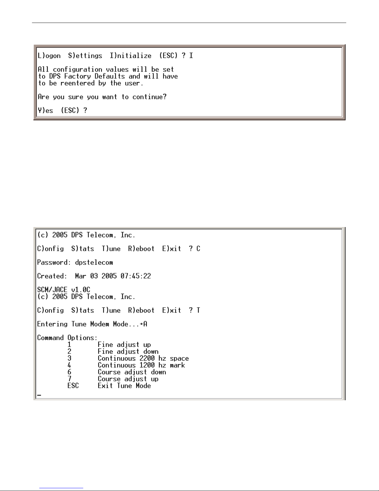
Information entered through the terminal interface is stored in the Site Controller SCM's nonvolatile RAM.
Erasing or overwriting the nonvolatile RAM will alter the Site Controller SCM's configuration.
C)onfig > I)nitialize sets all configuration values to factory default settings. The I)nitialize command will erase
the stored NVRAM profile, removing the configuration file and all other configuration information. If you
choose the I)nitialize command, a confirmation prompt will ask you to confirm your choice — see Figure 6.12.
Note:
Initializing the NVRAM will erase all configuration information. Do not initialize the NVRAM unless you
want to re-enter all configuration information.
Fig. 6.13.
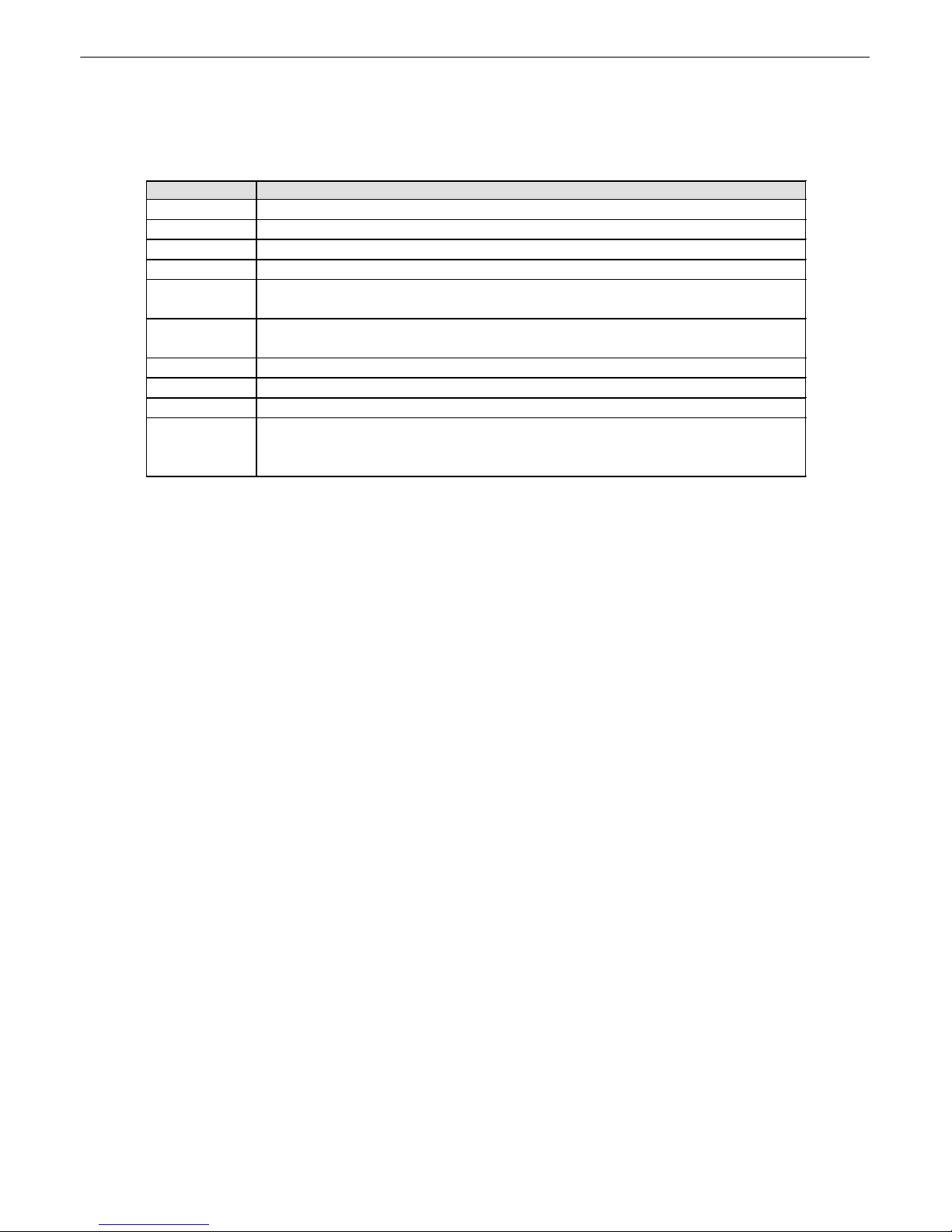
The A signifies that a modem tuning command has been acknowledged by the Site Controller SCM
It may be necessary to adjust the Site Controller SCM's internal modem to your network's requirements. To tune
the modem, choose C)onfig > T)une Modem.
You will see a menu as shown in Figure 6.13 above. After the menu, type a command. The modem is tuned using
the command characters described below in Table 6.A. When a valid command character is typed, the Site
NVRAM6.5
Tune 202 Modem6.6
Page 17
14
Controller SCM will return the character "A" (see Figure 6.13, above). If an unrecognized character is typed, the
Site Controller SCM will return the character "N."
The valid Tune Modem command characters are:
Command
Action
+
Enter Tune Modem command mode.
–
Exit Tune Modem command mode.
1
Adjust the modem transmit level one increment higher.
2
Adjust the modem transmit level one increment lower.
3
Transmit a continuous space level tone of 2200 Hz on the modem
output line.
4
Transmit a continuous mark level tone of 1200 Hz on the modem output
line.
5
Turn off the modem transmitter.
6
Adjust the modem transmit level ten increments lower.
7
Adjust the modem transmit level ten increments higher.
8
Transmit continuous alternating mark and space tones on the modem
output line. This is the equivalent of sending the ASCII character "U"
(hex 0x55).
Table 6.A.
Tune modem command characters
Your Site Controller SCM ships with the correct firmware already installed. You will need to upload firmware to
the unit only if an update is required.
To update the Site Controller SCM's firmware using ComLoaderW use the following steps:
1.
Power the Site Controller SCM.
2.
Connect the DB9 cable to the Site Controller SCM's front panel craft port and your PC COM port.
3.
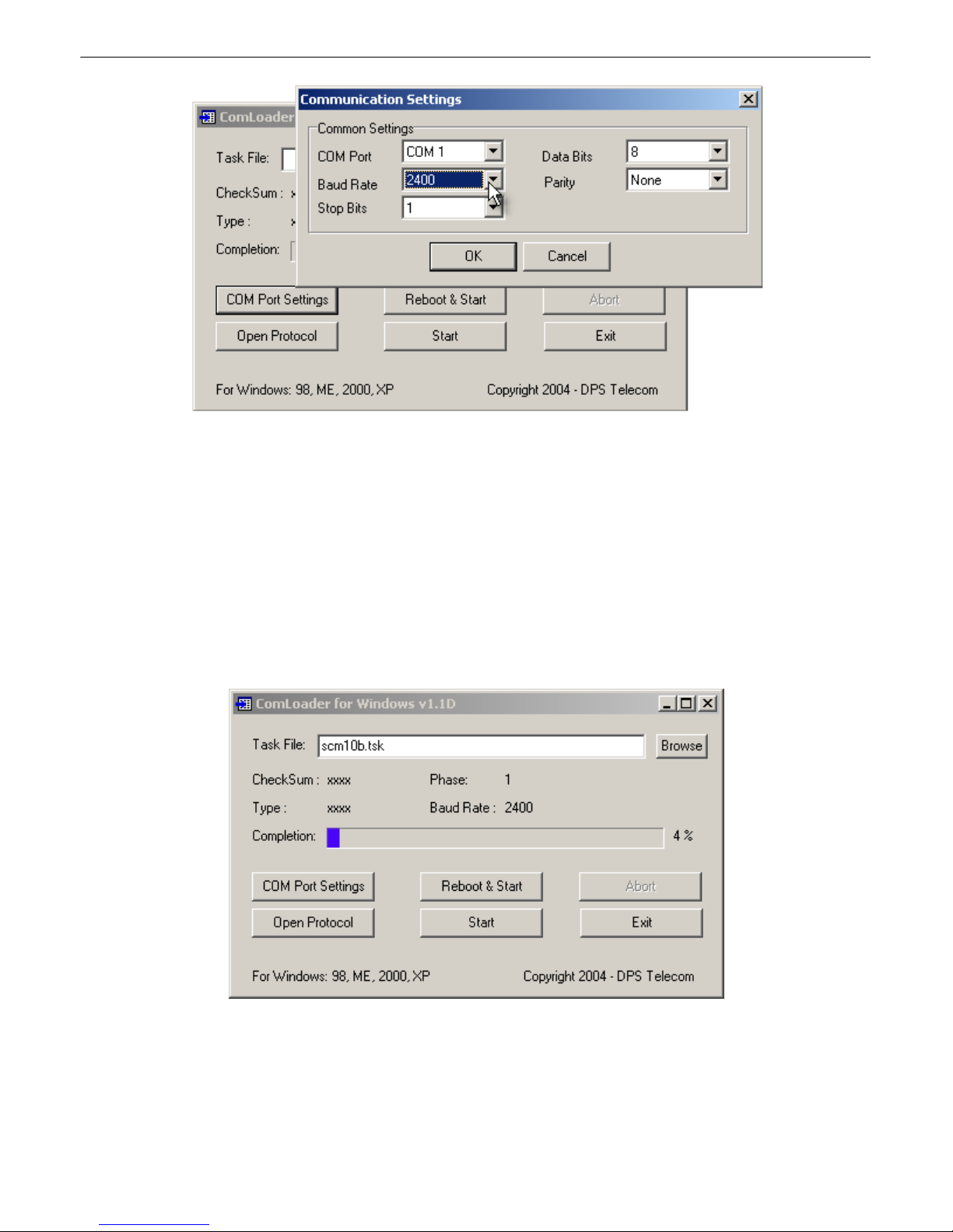
Select the COM port of your PC by clicking the COM Port Settings button. This will open the
Communications Settings dialog box, where you can select communications and flow control settings.
Select
2400 baud and no flow control
— see Figure 7.1.
Updating Firmware7
Page 18
15
Fig. 7.1.
Press the COM Port Settings button to select your COM port settings
4.
Select a task file by typing its path name in the Task File box or browse to the file by clicking the browse
button.
5.
Click the Start button. The firmware upgrade will be automatically uploaded to the Site Controller SCM.
Note: Do not abort or disturb the upgrade process in any way while uploading is in progress as this may
cause the unit to become inoperable.
While uploading, the ComloaderW screen will display the checksum, type, and phase of the task file and the baud
rate of your connection to the Site Controller SCM. The progress bar indicates the progress and completion of the
firmware upload.
Fig. 7.2.
The ComLoaderw screen will show the upload status
The Open Protocol button opens the Protocol screen. The Protocol screen is for troubleshooting purpose only. Do
not open the Protocol screen unless you are requested to do so by DPS Telecom Technical Support Personnel.
Once the firmware upload is finished, click the Exit button to exit ComloaderW.
Page 19

16
During firmware loading, the LEDs on the front panel will provide continuous feedback of the firmware loading
process.
While the firmware load is in progress, the LEDs will display the following:
1.
Alternating
RED-GREEN-RED
pattern when the firmware load software is detected.
2.
ALL
RED
when waiting for DPSLOAD signal.
3.
ALL
GREEN
when DPSLOAD signal received.
4.
SLOW
(1 LED step every 1.5 seconds)
RED
LED walk while flash memory is wiped. Each LED step means
16 K was overwritten with h ' FF.
5.
FAST
(5 LED steps every second)
RED
LED walk while data is received and committed to flash memory.
Each LED step means a data packet was processed.
6.
Alternating
ALL GREEN/ALL RED
pattern when main application boots following the firmware load.
LED Display7.1
Page 20

17
For technical support questions please call Tridium, Inc directly at 1(804) 747-4771, or visit their website at
www.tridium.com.
Technical Support8
Page 21

18
Page 22

19
Page 23

Warranty
DPS Telecom warrants, to the original purchaser only, that its products a) substantially conform to DPS' published
specifications and b) are substantially free from defects in material and workmanship. This warranty expires two years from
the date of product delivery with respect to hardware and ninety days from the date of product delivery with respect to
software. If the purchaser discovers within these periods a failure of the product to substantially conform to the specifications
or that the product is not substantially free from defects in material and workmanship, the purchaser must promply notify
DPS. Within reasonable time after notification, DPS will endeavor to correct any substantial non-conformance with the
specifications or substantial defects in material and workmanship, with new or used replacement parts. All warranty service
will be performed at the company's office in Fresno, California, at no charge to the purchaser, other than the cost of shipping
to and from DPS, which shall be the responsiblity of the purchaser. If DPS is unable to repair the product to conform to the
warranty, DPS will provide at its option one of the following: a replacement product or a refund of the purchase price for the
non-conforming product. These remedies are the purchaser's only remedies for breach of warranty. Prior to initial use the
purchaser shall have determined the suitability of the product for its intended use. DPS does not warrant a) any product,
components or parts not manufactured by DPS, b) defects caused by the purchaser's failure to provide a suitable installation
environment for the product, c) damage caused by use of the product for purposes other than those for which it was designed,
d) damage caused by disasters such as fire, flood, wind or lightning unless and to the extent that the product specification
provides for resistance to a defined disaster, e) damage caused by unauthorized attachments or modifications, f) damage
during shipment from the purchaser to DPS, or g) any abuse or misuse by the purchaser.
THE FOREGOING WARRANTIES ARE IN LIEU OF ALL OTHER WARRANTIES, EXPRESS OR IMPLIED,
INCLUDING BUT NOT LIMITED TO THE IMPLIED WARRANTIES OF MERCHANTABILITY AND FITNESS FOR
A PARTICULAR PURPOSE.
In no event will DPS be liable for any special, incidental, or consequential damages based on breach of warranty, breach of
contract, negligence, strict tort, or any other legal theory. Damages that DPS will not be responsible for include but are not
limited to, loss of profits; loss of savings or revenue; loss of use of the product or any associated equipment; cost of capital;
cost of any substitute equipment, facilities or services; downtime; claims of third parties including customers; and injury to
property.
The purchaser shall fill out the requested information on the Product Warranty Card and mail the card to DPS. This card
provides information that helps DPS make product improvements and develop new products.
For an additional fee DPS may, at its option, make available by written agreement only an extended warranty providing an
additional period of time for the applicability of the standard warranty.
Technical Support
If a purchaser believes that a product is not operating in substantial conformance with DPS' published specifications or there
appear to be defects in material and workmanship, the purchaser should contact our technical support representatives. If the
problem cannot be corrected over the telephone and the product and problem are covered by the warranty, the technical
support representative will authorize the return of the product for service and provide shipping information. If the product is
out of warranty, repair charges will be quoted. All non-warranty repairs receive a 90-day warranty.
Page 24
Free Tech Support is Only a Click Away
Need help with your alarm monitoring? DPS Information Services are
ready to serve you … in your email or over the Web!
Free Tech Support in Your Email: The Protocol Alarm Monitoring Ezine
The Protocol Alarm Monitoring Ezine is your free email
tech support alert, delivered directly to your in-box
every two weeks. Every issue has news you can use
right away:
Expert tips on using your alarm monitoring
•
equipment — advanced techniques that will save
you hours of work
Educational White Papers deliver fast informal
•
tutorials on SNMP, ASCII processing, TL1 and
other alarm monitoring technologies
New product and upgrade announcements keep
•
you up to date with the latest technology
Exclusive access to special offers for DPS
•
Telecom Factory Training, product upgrade offers
and discounts
To get your free subscription to The Protocol:
Email us at
Or register online at
www.theprotocol.com/register
Free Tech Support on the Web: MyDPS
MyDPS is your personalized, members-only online resource. Registering for MyDPS is fast, free,
and gives you exclusive access to:
• Firmware and software downloads and upgrades
• Product manuals
• Product datasheets
• Exclusive user forms
Register for MyDPS online at
www.dpstelecom.com/register
“We protect your network like your business depends on it”™
www.dpstelecom.com
4955 E. Yale • Fresno, CA 93727 • (559) 454-1600 • (800) 622-3314 • (559) 454-1688 fax
 Loading...