


Remote Power Switch AB6
USER MANUAL
Visit our website at www.dpstelecom.com for the latest PDF manual and FAQs.
February 6, 2017
D-UM-RSPDC-12011 Firmware Version 1.0C

Revision History
February 23, 2017
February 6, 2017
November 18, 2015
June 18, 2015
April 4, 2013
November 28, 2012
July 23, 2012
May 24, 2012
May 18, 2012
May 11, 2012
December 20, 2011
Updates to specifications and shipping list
Shipping list update
Specs update
Added Event Log Section
Added TTY power control feature
Added hardware and software sections for new AMM
Options; clarified D-Wire port functionality
Updated Shipping List
Updated Shipping List and UM Part Number
Updated Front Panel LEDs and Shipping List with D-Wire
Updated shipping list
Added Studded Power Block Cover information
December 8, 2011
September 9, 2011
Updated shipping list and fuse information
Added low voltage disconnect and password lockout
features
May 23, 2011
May 13, 2011
This do cument co ntains proprietary information which is protect ed by cop yrigh t. A ll rights are res erved. No p art o f this
document may be pho tocopied without prior written con sent of DPS Telecom.
All s oftware a nd manua ls are copyrigh ted by DPS Telecom. Said so ftware and manuals may not be rep rod uced, copied,
trans mitted or used to make a derivative work, by either mechan ical, electronic or any oth er means in whole or in part, withou t
prior written con sent from DPS Teleco m, except as req uired by United States cop yrigh t laws.
© 2017 DPS Telecom
Initial Release
Preliminary Release
Notice
The mate rial in this manu al is for information purpo ses an d is s ubject to chan ge without not ice. DPS Teleco m s hall not be
liable for errors co ntained herein or cons equ ential da mages in conn ection with the furnish ing, performance, or use of this
manual.

Contents
Visit our website at w ww.dps telecom.com for the late st PDF manual and FAQs
Introduction1 1
Specifications1.1 1
Shipping List1.2 3
Hardware Installation2 5
Tools Needed2.1 5
Mounting2.2 5
Power Connections2.3 6
Studded Power Block Cover2.4 6
Power Input Connection2.5 7
Power Output Connection2.6 8
Physical Power Switch Resources3 10
Front Panel LEDs3.1 10
Craft Port3.2 11
LAN Connection3.3 12
Breaker Switches3.4 12
Fuses3.5 13
Alarm Monitoring4 14
Discrete Alarms4.1 14
Analog Alarms4.2 15
Switching Analog Alarms to Current Operation4.2.1 16
D-Wire Sensor Input4.3 17
Control Relay Connectors4.4 17
Display Mapping4.5 18
Initial Configuration5 20
Connecting via the Craft Port5.1 20
Control Power via TTY5.1.1 21
Connecting via LAN5.2 22
Ethernet Configuration5.3 24
Temporarily Disabling the RPS Firewall5.3.1 24
Using the Web Interface6 26
Logging in to the Web Interface6.1 26
Navigating the Web Interface6.2 27
Provisioning the RPS6.3 28
System6.3.1 29
User Profiles6.3.2 30
Ethernet6.3.3 33

Firewall6.3.4 34
6.3.4.1
Disabling Protocols
SNMP6.3.5 36
Notifications6.3.6 38
6.3.6.1
6.3.6.2
6.3.6.3
6.3.6.4
Email Notification Settings
SNMP Notification Settings
Schedule
Testing Notifications
Power Feed Status (Provisioning)6.3.7 41
Base Alarms (Provisioning)6.3.8 43
User Controls (Provisioning)6.3.9 44
6.3.9.1
Configuring Derived Controls
User Analogs (Provisioning)6.3.10 45
Sensors (Provisioning)6.3.11 47
Power Control (Provisioning)6.3.12 48
6.3.12.1
Low Voltage Disconnect
System Alarms (Provisioning)6.3.13 50
Timers6.3.14 52
Date Time6.3.15 53
6.3.15.1
Testing your Automatic Time Adjustment (NTP) Settings
Operating the RPS6.4 55
Power Feed Status (Operation)6.4.1 55
Power Control (Operation)6.4.2 56
Base Alarms (Operation)6.4.3 57
User Controls (Operation)6.4.4 58
User Analogs (Operation)6.4.5 58
Sensors (Operation)6.4.6 59
System Alarms (Operation)6.4.7 59
Event Log6.4.8 61
Device Access6.5 61
Updating Firmware6.6 62
Frequently Asked Questions7 63
Technical Support8 64
End User License Agreement9 65

1
1
The Remote Power Switch (RPS AB6), is a rack-mountable power distribution unit (PDU) that allows
you to remotely power on/off and reboot critical devices from any computer on your network.
Via the RPS web browser, you'll be able to toggle power, monitor voltages (and threshold alarms) for
your power feeds, and see fuse-alarms. The web browser supports HTTPS (HTTP secure) for secure
browsing and a number of secure access profiles and password options are available to set access
rights for individual users who might access the RPS web browser.
The unit can also send SNMP traps and email notifications when power is switched on or off, when a
fuse alarm sets, or one of the inputs loses power, so you'll never have to make a trip out to a site to flip a
switch again.
Introduction
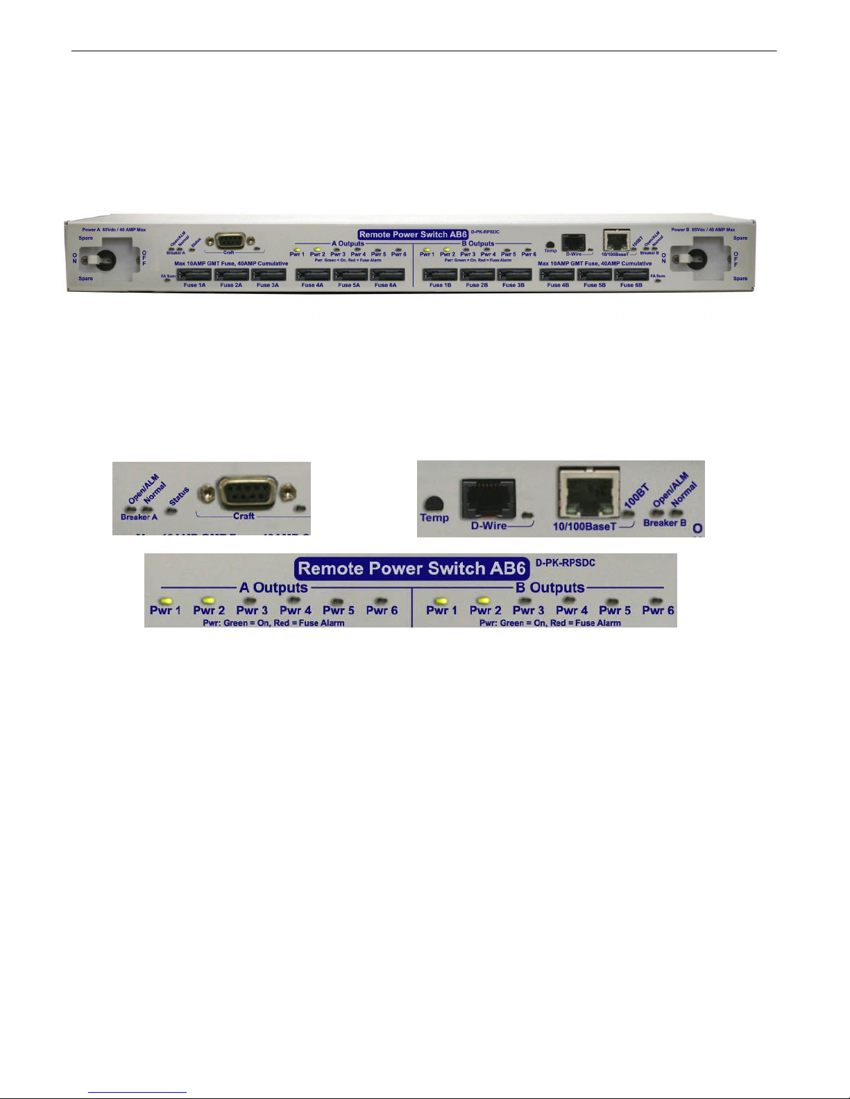
The RPS AB6 front panel
Specifications1.1
Power Inputs: 2 Studded Terminal Block inputs
Voltage: -48 VDC (-36 to -60 VDC) feeds (studded terminal blocks)
Current Draw: 350mA
Power Outputs: 12 (4 connectors, 3 outputs per connector)
Voltage: -48 VDC
Max Current per Feed: 8 Amps
Max Current per Set: 36 Amps per output group
GMT Fuse: 10 Amp max (1 per output)
Output Relays: 8A max @ 60V continuous
Note: Fuses are not included with the with the Remote Power Switch AB6. The user will need to
determine fuse ratings for slots appropriate to their needs (keeping in mind the 36 Amp maximum per
output group).
Interfaces: 1 DB9 RS232 Craft Port
1 RJ45 10/100 BaseT Ethernet Port
1 RJ-11 D-Wire Port
Spare Fuses: 0
Dimensions: 1.75"H x 17"W x 8.5" D
Weight: 5 lbs.
Mounting: 19" or 23" Rack
Visual Interface: 22 front-panel LEDs
2 back-panel LEDs
Operating Temperature: 32°–140° F (0°–60° C)
Operating Humidity: 0%–95% noncondensing
MTBF: 60 years

2
Windows Compatibility: XP, Vista, 7 32/64 bit
*RoHS 5 Approved

Shipping List1.2
Shipping List
Remote Power Switch AB6
D-PK-RSPDC
RPS AB6 User Manual
D-UM-RSPDC-12011
RPS AB6 Resource CD
(includes manuals, MIBs, and software)
DB9M-DB9F Download Cable 6 ft.
D-PR-045-10-A-04
23" Rack Ears
D-CS-325-10A-01
6-Pin DC Out Phoenix Connectors
(x4)
2-821-00762-06
19" Rack Ears
D-CS-325-10A-00
Ethernet Cable, 14 ft.
D-PR-923-10B-14
Metric Rack Screws (x4)
2-000-80750-03
Pads (x4)
2-015-00030-00
While unpacking the Remote Power Switch, please make sure that all of the following items are
included. If some parts are missing, or if you ever need to order new parts, please refer to the part
numbers listed and call DPS Telecom at (800) 622-3314.
3

4
3/8" Ear Screws (x8)
1-000-60375-05
5 Amp Fuse (x12)
2-741-10000-00
Standard Rack Screws (x4)
1-000-12500-06
10 Amp Fuse (x4)
2-741-05000-00
Nut With Star Washer (x9)
2-002-01421-00
Studded Power Block Cover (x2)
2-820-73175-01
Cable Ties (x4)
1-012-00106-00
Optional Accessories
D-Wire Temperature Sensor
D-PK-DSNSR-12001
6 Pin Connectors (For Controls) (x1)
2-821-10635-00
8 Pin Connectors (For Alarms and Analogs)
(x6)
2-821-10835-00

5
Phillips No. 2 Screwdriver
Small Standard No. 2 Screwdriver
7/16" Nut Driver
2
Hardware Installation
Tools Needed2.1
To install the Remote Power Switch, you'll need the following tools:
Mounting2.2
The RPS AB6 with 23" rack ear in flush mount position
The Remote Power Switch mounts in a 19" rack or a 23" rack using the appropriate rack ears for each
size. Attach the rack ears in the flush-mount location shown in the picture above.
Note: Rack ears can be rotated 90° for wall mounting or 180º for other mounting options (not shown).

6
Power Connections2.3
Both the Remote Power Switch AB6's power input and output connections are located on the unit's rear
panel.
The Remote Power Switch AB6 rear panel
Studded Power Block Cover2.4
Before the power input connections can be made the studded power block covers will need to be
removed. To do this use the DPS Standard No. 2 screwdriver. Use the leverage provided by the
screwdriver to lift the latching device as seen in the image below. Once the power connections are
made, ensure that the studded power block covers are reattached to the device.
How to remove the studded power block cover

Power Input Connection2.5
The Grounding Lug on the back of the unit provides a permanent connection to
earth ground when connected. The Grounding Lug must be used in order to
comply with standards.
The Remote Power Switch has 2 power feeds, 1 for each set of 6 outputs. Each feed consists of 4
screw-lug power connectors.
7
Input Feed B and the Grounding Lug for the RPS AB6
Before you connect a power supply to the Remote Power Switch, test the voltage of your
power supply:
· Connect the black common lead of a voltmeter to the ground terminal of the battery, and connect
the red lead of the voltmeter to the battery's –48 VDC terminal. The voltmeter should read
between –43 and –53 VDC. If the reading is outside this range, test the power supply.
To connect the RPS to a power supply:
Warning: Before connecting power feeds, make sure that the breaker for the power feed you're
connecting is switched off.
1. Use the grounding lug to connect the unit to earth ground. The grounding lug is next to the
symbol. Insert the eyelet of the earth ground cable between the two nuts on the grounding lug
(Ground cable not included). Tighten the grounding lug into place using your 7/16" nut driver.
2. Insert a batte ry ground into the lower terminal and tighten the nut down on the ground cable
using your 7/16" nut driver. If using the dual feed connector displayed in the example above,
tighten both nuts down on the connector.
3. Insert a –48 VDC line to the unit's upper terminal and tighten the nut down on the -48 VDC line.
If using the dual feed connector displayed in the example above, tighten both nuts down on the
connector.
4. Repeat Steps 2 and 3 for the remaining power inputs.
Note: You must connect A and B side power inputs to separate power supplies for your Remote
Power Switch to properly function.

8
5. Flip the breaker switch(es) to turn on power.
If the power feeds are connected correctly, you will see LED activity on the front-side of the unit.
Warning: You must connect both terminals on an input feed to output a full 40 Amps.
Power Output Connection2.6
The Remote Power Switch's power feeds are wired to 6-pin plug connectors, 3 per connector. For
each output feed, the -48V cable will be on the left and the ground cable (GND) will be on the right.
Power output connectors on the RPS AB6
To connect your power feeds:
1. If connected, remove the front panel fuse for the power input (or set of power inputs) you'll be working
with. (Example: If connecting input feeds A1-A3, ensure that fuses A1, A2, and A3 are disconnected.)
2. If connected, disconnect the 6-pin power connector from the remote power switch before wiring
power outputs.

Inserting the ground cable into appropriate terminal for the output connector
3. Connect the ground cable to the right terminal for each power output; using a small flathead
screwdriver, tighten the GND terminal.
4. Connect the -48V cable to the left terminal for each power output; using a small flathead screwdriver,
tighten the -48V terminal.
9
5. Once you've wired your equipment to the terminals on the 6-pin plug, connect the plug to the RPS
6. Screw-in the connector to ensure that it does not fall loose from the unit.
7. Re-insert the fuses for the outputs you've just connected.
A fully wired output connector
10
LEDs on the front panel of the RPS AB6
3
The Remote Power Switch's fuses, breaker switches, craft port, LAN, and indicator LEDs are all front-accessible.
Once you've wired power inputs and outputs to the unit, you can perform all other operations from the unit's front
panel.
Physical Power Switch Resources
The front panel of the RPS AB6
Front Panel LEDs3.1
Indicator LEDs for the RPS AB6 are all located on the front panel, and will alert you to the status of your
unit.

Front Panel LEDs:
LED
Status
Description
D-Wire
Blinking Green
Transmit over D-Wire
Blinking Red
Receive over D-Wire
Craft
Blink Green
Transmitting over craft port
Blink Red
Receiving over craft port
FA Sum
Solid Red
A fuse is blown/broken on one or more of the power
feeds
Pwr 1-6 (Output A/B)
Solid Red
A fuse is blown/broken on the feed
Solid Green
The output feed is powered
100BT
Solid Green
100 BT connection
Off
10 BT connection
Status
Blink Red
Bootloader application is active; the unit is starting up
Blink Green
The main application is active
Breaker A
Open/ALM
Solid Red = Power A switch is 'On'
Normal
Solid Green = Power A switch is 'Off'
Breaker B
Open/ALM
Solid Red = Power B switch is 'On'
Normal
Solid Green = Power B switch is 'Off'
11
Craft Port3.2
Remote Power Switch AB6 Front Panel Craft Connection
The unit's front-side craft port is used to access the TTY interface (for initial configuration and local
access to the unit).

12
RJ45 Ethernet Connection
8
7
5
6 Receive In– (RI–)
4
3 Receive In + (RI+)
2 Transmit Out– (TO–)
1 Transmit Out + (TO+)
Ethernet port pinout
LAN Connection3.3
Connect the RPS AB6 to LAN via the unit's front-side 10/100BaseT Ethernet port.
Breaker Switches3.4
The switches on the front panel of the remote power switch control the corresponding power inputs on
the backside of the unit. Use each switch to effectively turn on or off the power feeds on either side of
the unit.
Note: When turning on power using a breaker switch, the corresponding power feeds will honor the
user-set Power-On Sequence. For information about the Power-On Sequence, see the Power
Control (Provisioning) section of this manual.
Breaker Switches are located on the front panel of the RPS AB6
You can store one spare fuse in the small recess above and below each breaker switch.

Fuses3.5
The Remote Power Switch AB6's fuses are all located on the front side, each directly corresponding
with the power feeds in the back. Each of the unit's fuse slots accepts up to a 10 amp GMT fuse,
however, 10 Amp fuses are not required. The user should choose fuses rated to fit their application and
should not exceed 40 Amps-worth of fuses per 6-output side (A or B).
Fuse alarm LEDs are located above the fuses to visually indicate if any of the fuses are blown.
Additionally, from the blue Power Control option under the Operation Menus, you can operate your
power outputs and view the status of each feed as seen in section 5.4.2 Power Control (Operation)
13

14
4
Alarm Monitoring
Discrete Alarms4.1
The RPS AB6's discrete alarm inputs
The RPS AB6 features 16 discrete alarm inputs - also called digital inputs or contact closures. Discrete
alarms are either activated or inactive, so they're typically used to monitor on/off conditions like power
outages, equipment failures, door alarms and so on.
The RPS AB6's discrete alarm points are single-lead signals referenced to ground. The ground side of
each alarm point is internally wired to ground, so alarm points can either connect as a dry contact or a
contact to ground.
In a dry contact alarm, the alarm lead brings a contact to the ground lead, activating the alarm.
In a contact to ground alarm, a single wire brings a contact to an external ground, activating the alarm.
For a diagram, see the image below.
You can reverse the polarity of each individual discrete alarm point, so that the alarm is activated when
the contact is open.
Discrete alarm points can connect as a dry contact or a contact to ground

Analog Alarms4.2
The RPS AB6's analog alarm inputs
The RPS AB6's 8 analog alarm inputs measure continuous ranges of voltage or current. Analog alarms
are typically used to monitor battery voltage, charging current, temperature or other continuously
variable conditions.
The measurement range of the analog channels is –90 to +90 VDC or 4 to 20 mA.
You can connect analog alarm inputs to the RPS AB6 by using the 8-pin analog alarm connectors. For
the 8-pin analog connector's pinout information, see the figure below.
15
8-Pin Analog Connector Pinout
By default, the analog inputs are configured to measure voltage. You can switch the analog inputs to
measure current by resetting jumpers on the RPS AB6's circuit board. For instructions, see Section
4.2.1, "Switching Analog Alarms to Current Operation."

16
4.2.1 Switching Analog Alarms to Current Operation
Adjustable jumpers on the RPS Ab6 circuit board
By default, the analog inputs are configured to measure voltage. You can switch the analog inputs to
measure current by resetting jumpers on the RPS AB6's circuit board.
WARNING: Always observe anti-static precautions whenever opening the unit.
To test the analog alarm voltage/current jumpers, follow these steps:
1. Make sure the RPS AB6 is depowered and disconnected from all network connections.
2. Remove the screws from the sides of the RPS AB6 case.
3. Slide off the top cover of the case to expose the circuit board.
4. The adjustable jumpers are shown in the figure above. All alarm inputs can be individually
configured for current or voltage operation.
Jumper installed for current
Current
4 to 20 mA
Current Source
Transducer
Voltage
Voltage Source
Transducer
250 Ohm
Shunt
+
Analog
Channel
Input
-
Jumper removed for voltage
+
Analog
Channel
Input
-
Unjumpered/Open Position:
Voltage Operation (default)
Jumpered/Closed Position:
Current Operation
Jumper settings for analog alarm inputs

5. By default, all jumpers are in the unjumpered/open position, which corresponds to voltage
operation, as shown in figure above. To reset an analog alarm input to current operation, reset its
jumper in the closed position.
Note: Each jumper inserts a 250-ohm shunt resistor across the input. This must be taken into
account when defining the analog input reference scale.
6. Slide the top cover of the case back into position and replace the screws.
7. Reconnect and power up the RPS AB6.
D-Wire Sensor Input4.3
The port on your RPS AB6 labeled, "D-Wire" supports the connection of up to 16 D-Wire sensors. The
RPS AB6 powers and communicates with your D-Wire sensors via straight-through RJ-11 cables.
Connecting D-Wire Sensors
Using a 6P4C, straight-through RJ-11 cable (part #D-PR-045-10A-01, pinout below), connect the D-
Wire sensor port on the RPS AB6 to the In jack on a D-Wire sensor. Chain additional sensors to the
RPS AB6 (using the same straight-through cables) from the Out jack on the previous sensor to the In
jack on the next (i.e. Out on sensor 4 to In on sensor 5).
17
Pinout for D-Wire RJ-11 jacks
For details about configuring your sensors though the web interface, see the Provisioning > Sensors
section of this manual.
Control Relay Connectors4.4
The RPS AB6's control relay inputs
A 6-pin connector for two control relays is located on the RPS AB6's back panel.

18
Description
Port
Address
Point
Display 1
Power outputs side A fuse alarms
9911-6
Power outputs side B fuse alarms
9917-12
Side A breaker alarm
99113
Side B breaker alarm
99114
Power outputs side A
99117-22
Power outputs side B
99123-28
User Controls
99129-30
System alarms
99133-64
Display 2
Base Alarms
9911-16
Undefined
99117-64
Display 3
Side A power feed alarms
9911-5
Side A power feed value
9916-64
Display 4
Side B power feed alarms
9911-5
Side B power feed value
9916-64
Display 5
User Analog 1 alarms
9911-5
User Analog 1 value
9916-32
User Analog 2 alarms
99133-37
User Analog 2 value
99138-64
Display 6
User Analog 3 alarms
9911-5
User Analog 3 value
9916-32
User Analog 4 alarms
99133-37
User Analog 4 value
99138-64
Display 7
User Analog 5 alarms
9911-5
User Analog 5 value
9916-32
User Analog 6 alarms
99133-37
User Analog 6 value
99138-64
Display 8
User Analog 7 alarms
9911-5
User Analog 7 value
9916-32
User Analog 8 alarms
99133-37
User Analog 8 value
99138-64
Display 9
Digital Sensor 1 alarms
9911-5
Digital Sensor 1 value
9916-32
Digital Sensor 2 alarms
99133-37
Digital Sensor 2 value
99138-64
Display 10
Digital Sensor 3 alarms
9911-5
Digital Sensor 3 value
9916-32
Digital Sensor 4 alarms
99133-37
Digital Sensor 4 value
99138-64
Display 11
Digital Sensor 5 alarms
9911-5
Digital Sensor 5 value
9916-32
Digital Sensor 6 alarms
99133-37
Digital Sensor 6 value
99138-64
Display Mapping4.5

19
Display 12
Digital Sensor 7 alarms
9911-5
Digital Sensor 7 value
9916-32
Digital Sensor 8 alarms
99133-37
Digital Sensor 8 value
99138-64
Display 13
Digital Sensor 9 alarms
9911-5
Digital Sensor 9 value
9916-32
Digital Sensor 10 alarms
99133-37
Digital Sensor 10 value
99138-64
Display 14
Digital Sensor 11 alarms
9911-5
Digital Sensor 11 value
9916-32
Digital Sensor 12 alarms
99133-37
Digital Sensor 12 value
99138-64
Display 15
Digital Sensor 13 alarms
9911-5
Digital Sensor 13 value
9916-32
Digital Sensor 14 alarms
99133-37
Digital Sensor 14 value
99138-64
Display 16
Digital Sensor 15 alarms
9911-5
Digital Sensor 15 value
9916-32
Digital Sensor 16 alarms
99133-37
Digital Sensor 16 value
99138-64
The RPS AB6 display mapping

20
5
Before you can incorporate the Remote Power Switch into your network, you must configure its ethernet
port. Initial configuration for your Remote Power Switch's ethernet settings is performed via the TTY
interface. To access the TTY interface, you will establish a craft port connection with your remote
power switch using the included serial cable (recommended), a USB to serial connection, or a LAN
connection that mimics the unit's factory-set IP address and subnet mask.
You may also use the TTY interface to locally interface with the RPS, however, some advanced
configuration, monitoring, and control options may not be available via TTY. For more advanced options,
use the RPS's secure web browser interface.
Initial Configuration
Connecting via the Craft Port5.1
RPS AB6 Craft Port
The easiest way to connect to your Remote Power Switch is over a physical cable connection between
your PC's COM port and the Remote Power Switch's craft port.
Use the DB9M-DB9F download cable provided with your Remote Power Switch to make a craft port
connection.
1. Open HyperTerminal (or a similar terminal emulation program) and create a new connection/session
with the following COM port options and click OK:
. • Bits per second: 9600
• Data bits: 8
• Parity: None
• Stop bits: 1
• Flow control: None

2. Press Enter
21
Setting up a serial connection using HyperTerminal
3. Enter the default login information.
• Username: admin
• Password: dpstelecom
See Ethernet Configuration later in this chapter to continue configuring your Remote Power Switch's
ethernet port.
5.1.1 Control Power via TTY
After you have connected via the craft port, you can use the TTY interface to access the Power
Controls:
1. Press M)onitor.
2. Press P)owerControls
The TTY interface login screen

22
Status
Description
On (O)
Turn on power.
Off (F)
Turn off power.
Reset (R)
Temporarily turns off power before turning it back on again.
Print Summary (P)
View a list of relay states and fuse statuses.
(ESC)
Go back to the previous menu.
From here you can view the ID, Description, Fuse status (OK/Fail), and PowerState (On/Off).
You also have access to the following commands:
Connecting via LAN5.2
Ethernet port
If you have physical access to the Remote Power Switch, it is easier to connect to the unit through
the craft port and assign it an IP address. Then you can complete the rest of the unit configuration over
a remote LAN connection, if you want. For instructions, see the previous section.

If you DON'T have physical access to the Remote Power Switch, you can make a LAN connection
to the unit by temporarily changing your PC's IP address and subnet mask to match the Remote Power
Switch's factory default IP settings. Follow these steps:
1. Look up your PC's current IP address and subnet mask, and write the information down; you will
be temporarily changing your PC's IP and subnet mask to access the RPS.
2. Reset your PC's IP address to 192.168.1.200.
3. Reset your PC's subnet mask to 255.255.0.0. You may have to reboot your PC to apply your
changes.
4. Once the IP address and subnet mask of your computer coincide with the Remote Power
Switch's, you can access the Remote Power Switch via a Telnet session at port 2002 or via
Web browser using the Remote Power Switch's default IP address, 192.168.1.100.
5. Provision the Remote Power Switch with the appropriate information (see Ethernet
Configuration later in this chapter or Configuring the RPS (Edit Menu) for more information),
then change your computer's IP address and subnet mask back to their original settings -- the
information you wrote down in Step 1.
23
See the following section, Ethernet Configuration, to continue configuring your Remote Power
Switch's ethernet port.

24
Ethernet Configuration5.3
The Remote Power Switch must be assigned an IP address before you will be able to connect via LAN/
WAN using a Telnet client or a Web browser. To connect via LAN, the minimum configuration requires
setup of the IP address and subnet mask. Minimum WAN configuration requires that the default gateway
be set as well.
Note: Instructions and Screenshots related to the Remote Power Switch TTY Interface are based on
firmware version 1.0. Later versions of the Remote Power Switch firmware may support additional
options.
Configure the Ethernet port parameters from the TTY Interface
To access your Remote Power Switch's Ethernet settings from the main TTY menu:.
1. Press C for the C)onfig menu.
2. Press E for the E)thernet menu.
3. Configure the Unit's address, Subnet mask, and default Gateway.
4. Press ESC to escape to the Ethernet menu.
5. Press B to perform a soft reboot of the unit.
6. Now you can connect to the unit via LAN and use the unit's Web Browser Interface to complete
configuration of the RPS.
5.3.1 Temporarily Disabling the RPS Firewall
If your firewall settings are keeping you from accessing the Remote Power Switch's web interface, you
can temporarily disable the unit's firewall to gain access to unit's web interface from the TTY interface
via craft serial connection. The Firewall, disabled in this way, is turned-off until you write new changes
to the unit or reboot. To temporarily disable the firewall, access the F)irewall option from the E)thernet
menu.
Note: The Remote Power Switch's firewall cannot be configured via the TTY interface. This option is

provided purely as a means to circumvent the firewall in the event that your whitelist/blacklist blocks
legitimate users out of the unit's web interface. To configure the unit's web interface, visit the Firewall
section later in this manual.
25

26
6
The Remote Power Switch AB6 features a built-in web browser interface for configuring and monitoring
the unit through the Internet or your Intranet.
Note: Only one user may remotely access the Remote Power Switch via the web browser interface at
a time.
Using the Web Interface
The Web Interface allows you to configure your unit, monitor your input feeds, and control your power
outputs
Note: Instructions and Screenshots related to the Remote Power Switch Web Interface are based on
firmware version 1.0. Instructions and images may differ from later versions of the Remote Power
Switch firmware.
Logging in to the Web Interface6.1
To login to the unit's web interface, simply type the IP address of the Remote Power Switch into the
address bar of your web browser. You will be prompted for your username and password.
The default username is: admin
The default password is: dpstelecom
DPS Telecom strongly recommends you change your username and password and set user profiles for
users who will access the RPS. See User Profiles for more information.

Navigating the Web Interface6.2
To navigate to any section of the web interface, simply click the links on left side of the interface.
The Web Interface is split into 3 sections:
· The blue Operation menus provide access to monitor and control your power feeds.
· The green Provisioning menus are where you'll configure your unit, alarm thresholds, and
notifications.
· The pink Device Access options provide access to logs of RPS AB6 activity and abilities to read,
write, reboot, and initialize the unit.
27

28
Provisioning the RPS6.3
Remote Power Switch configuration is performed from the Provisioning menus, the menu options in
green on the left-side of the web interface. The following pages provide a brief description of the options
available in each menu.
Saving Configuration Changes to the Remote Power Switch:
At the bottom of each screen you access from the Provisioning Menu, you will see a Save button.
Clicking Save will cache your changes locally. The web interface will then prompt you to either Write
your changes to the unit or Reboot the unit for changes to take effect in the top-left corner of your
browser. The relevant options will be highlighted in the Device Access options.
Note: If the unit prompts you to both Write changes to the unit and Reboot, you will Write your changes
first. Rebooting before without writing to the unit (if a Write is required) will cause you to lose your
configuration changes.
Status messages on the RPS AB6, inform you how to implement your changes
The control menu highlights items that must be completed for your changes to take effect

6.3.1 System
Global System Settings
Name
A name for this Remote Power Switch.
Location
The location of this Remote Power Switch.
Contact
Contact telephone number for the person responsible for this Remote
Power Switch. (Optional field)
Legal Warning
If not blank, the text in this field will popup after every login
DCP Re sponder Se ttings (For use with T/Mon)
DCP over LAN
Enables DCP transmissions over LAN (Disabled by default)
DCP Unit ID/Protocol
User-definable ID number for this Remote Power Switch (DCP Address),
and the DCP protocol being used (DCPx or DCPf).
DCP over LAN port/
Protocol
Enter the DCP port for this Remote Power Switch (UDP/TCP port).
Clicking the Provisioning option labeled System will take you to the System Options page. From here,
you will configure system information and global DCP settings.
29
The System menu
Once you've entered/modified your system settings, click Save in the bottom-left corner of the window
to cache your changes.

30
6.3.2 User Profiles
Clicking User Profiles gives you access to modify the default username and password, and to edit the
administrator profile and create up to 9 additional unique user profiles, each with different access rights
to the Remote Power Switch.
The User Profiles screen shows you at a glance whether a profile is active, suspended, or not yet
configured
To create or edit any the 10 user profiles (including the default), click the Edit button.
The Administrator Profile:
The first user profile in the User Profiles menu is the Administrator's Profile. Access rights for the
administrator's profile are all enabled and may not be disabled, nor can the profile be deleted or
suspended. This is a precaution to prevent a situation in which an access right is disabled for all users.
You may still edit the Username, Password, and Active Days fields for the Administrator Profile.

Configure access privileges for users in the User Profile screen
Profile Field
Description
Suspend this Profile
If this box is checked, the profile will not be able to access the RPS
Active Days
This field determines the number of days a profile will be active before the
user is required to update their password.
Note: Changing this field will reset the Active Day Count.
Max number of failed
logon attempts
Indicates the number of times the user may attempt to logon. If the user fails
to login within the number of attempts specified, the remote power switch will
lock out all users without the Edit logon profiles access privilege for 15
minutes.
User
Enter a username or a user description
Password
Enter a unique user password Note: All passwords are AES 128 encrypted.
Confirm Password
Re-enter the password.
Access Privileges
Edit logon profiles
Enables the user to add/modify user profiles and password information.
Edit Date Time Page
Allows the user to edit the unit's date, time, and NTP server
Write Config
(Change Unit
Configuration)
Enables the user to change the unit config by accessing the Write feature in
the control menu.
View Operation
Pages
Allows the user to access Operation menu options.
Send Power
Controls
Enables the user to issue On, Off, and Reboot commands to the RPS Power
Outputs.
TTY Access (access
via Craft port or via
Telnet)
Grants the user access to the unit via TTY interface (via craft or telnet)
Initialize config to
factory defaults
Allows the user to use the Initialize option in the Device Access menu,
resetting the Remote Power Switch to factory default settings. (All user
settings will be lost.)
Upload new firmware
or new config
Allows the user to upload firmware or backed-up configuration files
Get Audit Log
Allows the user to access the Audit Log (Ge t Log command)
Purge (delete) audit
log
Allows the user to delete the audit log (Purge Log command)
Get (backup) config
Enables the user to backup the unit's configuration files to be restored later.
Remotely reboot the
unit
Enables the user to reboot the unit remotely.
From here, you can change all configurable settings for a user profile.
31
User profile field descriptions
Once you've finished configuring a profile, click Save to store your changes locally.
To access another profile, simply click Go to profiles summary at the bottom of the page. You may

32
also navigate away from the user profiles screen at any time by clicking any of the menu options on the
left side of the screen.

6.3.3 Ethernet
Ethernet Settings
MAC Address
Hardware address of the Remote Power Switch (DC). (Not editable - For
reference only.)
Host Name
Enter a Host Name for easy-access via the web browser. Example: If you don't
want to remember this unit's IP address, you can type in a name is this field,
such as RPSAB6. Once you save and reboot the unit, you can now browse to it
locally by simply typing in "RPSAB6" in the address bar. (no "http://" needed).
Enable DHCP
Used to turn on Dynamic Host Connection Protocol. NOT recommended
because the unit is assigned an IP address from your DHCP server. The IP
you've already assigned to the unit becomes inactive. Using DHCP means the
unit will NOT operate in a T/Mon environment.
Unit IP
IP address of the Remote Power Switch.
Gateway
An important parameter if you are connected to a wide-area network. It tells the
Remote Power Switch (DC) which machine is the gateway out of your local
network. Set to 255.255.255.255 if not using. Contact your network administrator
for this info.
Subnet Mask
A road sign to the Remote Power Switch, telling it whether your packets should
stay on your local network or be forwarded somewhere else on a wide-area
network.
DNS Server 1
Primary IP address of the domain name server. Set to 255.255.255.255 if not
using.
DNS Server 2
Secondary IP address of the domain name server. Set to 255.255.255.255 is not
using.
From the Ethernet Menu, you may define and change your unit's Ethernet settings.
33
Edit Ethernet Options

34
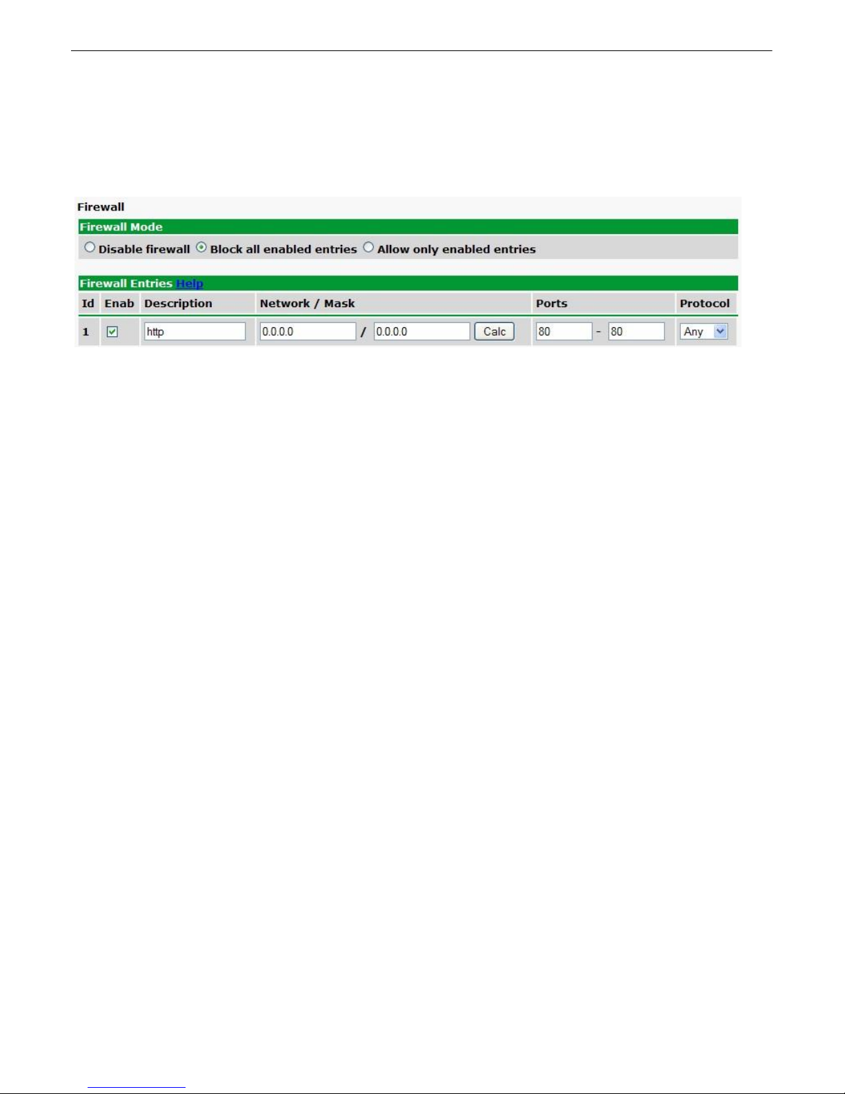
6.3.4 Firewall
From the Firewall menu, you can deny or allow access to the RPS AB6 by IP Address, Subnet Mask,
Port, or Protocol. By default, the firewall option is disabled
The Firewall option allows you to filter IPs or setup a white-list of allowable connections
To enable the Remote Power Switch's firewall, simply click the radio button to determine how you want
the firewall to behave.
· Block all enabled entries puts the firewall in Black List Mode. This option blocks packets from the
IP addresses/subnet masks in the Firewall Entries list.
· Allow only enabled entries puts the firewall in White List Mode, allowing only IP addresses/subnet
masks in the Firewall Entries list to access the Remote Power Switch.
In the Firewall Entries section of the page, simply enter the relevant information for the filter: IP
Address, Subnet Mask, Ports, or Protocols. The Enab button allows you to include or exclude
addresses in the Firewall Entries table from the behavior set by the Firewall Mode. Click the checkbox
to subject the entry to the firewall, and uncheck it to exclude it from the list.
When adding an entry, the Calc button will show you, by combination of the IP address and Network
Mask entered, what network (or address) will be affected by the Network/Mask combination you've
entered.
6.3.4.1 Disabling Protocols
Using the Remote Power Switch's Firewall feature, you can block access to the unit from certain
protocols by blocking all IP addresses on the port on which the protocol operates. To disable access in
this manner, the AB6 must operate in Black List Mode.
To block all all IP addresses on a particular port:
1. Click the Block all enabled entries radio button.
2. On an open Firewall Entry, change both of the Ports fields to the port number of the protocol you
wish to disable
· i.e. for HTTP, set both port fields to 80. (HTTP operates on port 80)
· for Telnet, block port 2002
· for HTTPS, block port 443
3. Change both the Network / Mask fields to 0.0.0.0. This tells the the AB6 to block all IP addresses on
the specified port.
4. Set the protocol to TCP
35
Note: Make sure you block only the ports associated with the protocol you wish to disable. Leaving the
Ports fields unaltered while setting the Network and Mask fields to 0.0.0.0 will block all IP access to
the unit (blocking all IP addresses on all ports).
You can block SNMP (default, port 162) or DCP (default, 2001) protocols in this manner, however, you
can also disable those features entirely from the SNMP and System tabs respectively.

36
6.3.5 SNMP
From the SNMP menu, you can configure SNMP
Configure SNMP settings for up to 3 users

37
Global Settings
Get
Community name for SNMP requests.
Set
Community name for SNMP SET requests.
Read and Write
Access
This field defines how the Remote Power Switch unit may be accessed via
SNMP. This can be set to the following:
· Access Disabled- Restricts all access to unit via SNMP
· SNMPv3-Only- Allows SNMPv3 access only
· SNMPv3 and SNMPv2c only- Allows SNMPv3c and SNMPv2c access only
· SNMPv3, SNMPv2c, and SNMPv1y- All- Allows you to read or write using any
version of SNMP (v1, v2c, v3)
v3-Users
ID
The user number designated for a v3-user. The RPS AB6 supports up to 3
SNMPv3-User profiles.
Username
The name of the user for which an SNMPv3 management operation is
performed.
Auth Type
This identifies the security modes available when SNMPv3 is utilized. The
modes are as follows:
· No-Auth- This access mode does not require authentication. This mode is
the least secure and is comparable to v1 and v2c.
· MD5- Provides authentication based on the MD5 algorithm.
· SHA1- Provides authentication based on the SHA algorithm and provides
Priv Type
· DES- Not yet implemented
· AES- Provides AES encryption
· No Priv - No encryption
Auth Pass
This field contains the password used with either MD5 or SHA authentication
algorithms.
Priv Pass
This field contains the password used with privatization encryption.
Available fields in the SNMP configuration menu

38
6.3.6 Notifications
From the Notifications menu, you can set up to 8 different notifications and recipients for events reported
by the RPS AB6.
The Edit > Notifications menu
The notifications menu will show you a list of currently configured notifications
· Notify On shows what events will trigger a notification.
o Disabled indicates that the notification is not currently enabled
o Alarms indicates that notification will be sent when alarms set
o Clears indicates that notification will be sent when alarms clear
o Both indicates that notifications will be sent when alarms set or clear
· The Type field shows the type of notification being sent. The Remote Power Switch is capable of
sending Email notification or SNMP Traps when events occur.
· The Details field shows the server being used for SNMP notifications, if SNMP notifications are
enabled.
To send a test notification, click Test
To configure any of the unit's notifications, click Edit.
The Notification # menu
1. In the drop-down box, choose whether you'd like to receive notification for alarms, clears, or both.
You may also disable the notification by selecting the appropriate option.
2. Next, choose the sort of notification you would like sent when an event occurs. You may choose:
· Send Email to have an email sent when events occur
· Send SNMP to have a trap sent when events occur
3. Click Save and Ne xt to continue configuring notifications.

6.3.6.1 Email Notification Settings
Email Notification
SMTP Server IP or
Host Name
The IP address of your email server.
Port Number
The port used by your email server to receive emails, usually set to
25.
"From" E-mail
Address (Global)
The email address that the Remote Power Switch will send all email
notifications from. The address in this field applies to all email
notifications. Changing the "From email address" for any one email
notification type will automatically apply to all email notifications for the
RPS.
"To" E-mail Address
The email address of the person responsible for this Remote Power
Switch, who will receive email alarm notifications.
39
Editing Email Notification Settings
4a. Enter the appropriate information for email notifications in the fields of the Email Notification screen.
Click Sav e and Next to continue.
If you want to send authenticated emails, click the appropriate radio button. If you enable POP
authentication, you will have to enter the relevant authentication information the fields below.

40
SNMP Notification
SNMP Trap Server IP
The SNMP trap manager's IP address.
Trap Port No.
The SNMP port (UDP port) set by the SNMP trap manager to
receive traps, usually set to 162.
Trap Community
Community name for SNMP TRAP requests.
Trap Type
Indicate whether you would like to send SNMPv1, v2c, or v3 traps
SNMPv3 user
Choose the SNMP user from the drop-down box. SNMP users
are configured from the SNMP menu.
Notification Scheduling
Days of the week
From either Schedule 1 or 2, check which days you want to receive
notifications.
Any Time
Select to tell the Remote Power Switch you want to receive alarm
notifications at any time for the day(s) you've selected.
Notification Time
Instead of "Any Time", use these fields to only send alarm notifications
during certain hours on the day(s) you've selected.
6.3.6.2 SNMP Notification Settings
Configuring SNMP notifications
4b. Enter the appropriate information for SNMP Trap notifications in the fields of the SNMP Notification
screen. Click Save and Next to continue.
6.3.6.3 Schedule
The Schedule creation screen

Click Save and Finish to save the notification.
6.3.6.4 Testing Notifications
To test your Notifications to ensure that they are correctly configured:
1. Click the Test button next to any of your notifications. The system will ask you to confirm that you
would like to send a test. Click OK.
The Test button allows you to check your Notification Settings
2. Go to the System Alarms page and see if the Notification alarm for the notification you just tested
has set.
· If the Notification 1-8 failed alarm displays as in the example below (the state shows Alarm in red),
then your notification settings are incorrect.
· If the Notification 1-8 failed alarm state displays Clear with a green background, then your
notification settings are correct.
41
The NTP alarm will show you if your NTP Settings are correct
6.3.7 Power Feed Status (Provisioning)
From the green Power Feed Status option under the Provisioning heading, you can set thresholds
alarms for your power input feeds and determine notifications for power input alarms.
Set notifications and threshold alarms for your input feeds from the Provisioning > Power Feed Status
screen

42
For both of your unit's input feeds:
· Set a Description for each of the unit's input feeds, and
· Click any of the checkboxes 1-8 to indicate what notifications you want the RPS AB6 to send for each
particular input alarm.
Click Details to reveal the thresholds for input alarms. All thresholds are listed in Voltage.
· MjU indicates a Major Under alarm (low voltage). The default value is -40Vdc
· MnU indicates a Minor Under alarm (low voltage) The default value is -45Vdc
· MnO indicates a Minor Over alarm (high voltage) The default value is -55Vdc
· MjO indicates a Major Over alarm (high voltage) The default value is -60Vdc
Once you've configured alarm thresholds and notifications for your power inputs, click Save to commit
your changes locally.

6.3.8 Base Alarms (Provisioning)
Basic Alarm Configuration
ID
Alarm ID number.
Description
User-definable description for the discrete alarm point.
Rev (Reverse)
Reverse: Check this box to reverse the polarity of the alarm point. Leaving
this option un-checked means a normally open contact closure is an alarm.
When polarity is reversed, a normally closed alarm point is clear when
closed.
Notification Devices
Check which notification device(s), 1 through 8, you want to send alarm
notifications for that alarm point.
Discrete alarms are configured from the Provisioning > Alarms menu. Descriptions for the alarm
points, polarity (normal or reversed) and notification type(s) are defined from this menu. You also have
the option to use Basic or Advanced configuration methods, explained in this section.
43
The Provisioning > Alarms menu

44
Advanced Alarm Configuration (Advanced>>)
On Set
User-definable description (condition) that will appear for the discrete alarm
input on Set. Example: "Alarm" or "Urgent."
On Clear
User-definable description (condition) that will appear for the discrete alarm
input on Clear: "Example: "Alarm Cleared".
Qual. Time
(Qualification Time)
The length of time that must pass, without interruption, in order for the
condition to be considered an Alarm or a Clear.
Qual. Type
(Qualification Type)
Allows you to choose whether you want to apply the Qualification Time to the
alarm Set, Clear, or Both.
Basic Controls Configuration
ID
ID number for the control relay.
Description
User-definable description for the NetGuardian's control relay.
Advanced Control Configuration (Details>>)
Momentary Time
Control on time (in milliseconds) when you execute the MOM command.
Max limit of 600 seconds.
Derived Control
See Section 6.3.9.1, "Configuring Derived Controls."
Notification Devices
Check which notification device(s), 1 through 8, you want to send alarm
notifications for the control relay.
6.3.9 User Controls (Provisioning)
The RPS AB6's 2 control relays can be configured in the Provisioning > Controls menu. You can
enter your own description for these relays and designate them to a notification device(s).
The Provisioning > Controls screen
6.3.9.1 Configuring Derived Controls
The RPS AB6's Derived controls can be configured in the Provisioning > User Controls > Details>>
tab. You can enter your own equation next to "Derived Control:".
Derived controls can be created from derived formulas using the following operations:
_OR : Set the current operation to OR.
_AN : Set the current operation to AND.
_XR : Set the current operation to XOR.

D : Tag to change the active display number.
. : Used like a comma to delimit numbers.
- : Used to specify a range of points.
Spaces included here are for readability purposes only.
Hot Tip!
!
· Precedence of the operations are always left to right.
· All number references can either be one or two digits.
_OR D1.3-5 is logically equivalent to (1.3 || 1.4 || 1.5)
_AN D 1.3-5 D2.6 _OR D3.7 is logically equivalent to ((1.3 && 1.4 && 1.5 && 2.6) || 3.7)
_OR D01.03-05 D02.06 _AN D02.07 D03.10.-12 is logically equivalent to ((1.3 || 1.4 || 1.5 || 2.6&& (2.7
&& 3.10 && 3.12))
_AN D1.3-5D2.6_OR.7D3.10.12 is logically equivalent to ((1.3 && 1.4 && 1.5 && 2.6 ) || 2.7 || 3.10 ||
3.12))
6.3.10 User Analogs (Provisioning)
45
The RPS AB6 has 8 user-definable analog channels. Each channel must be individually configured to
monitor data.
Note: Only analogs supported by the units hardware will appear in the NetGuardian web browser
interface.

46
Basic Analog Configuration
ID
Analog ID number.
Enab
Check this box to enable the analog.
Description
User-definable description for the analog channel.
Notification Devices
Check which notification device(s), 1 through 8, you want to send alarm
notifications for that alarm point.
Advanced Analog Configuration (Details>>)
Record Freq
The amount of time, in minutes (min) or seconds (s), between each log of
each analog value to history.
Deadband
The amount (in volts) that the channel needs to go above or below a
threshold in order to cause an alarm.
On Set
User-definable description (condition) that will appear for the temperature
alarm on Set. Example: "Alarm".
On Clear
User-definable description (condition) that will appear for the temperature
alarm Clear. Example: "Alarm Cleared".
Qual. Time
(Qualification Time)
The length of time that must pass, without interruption, in order for the
condition to be considered an Alarm or a Clear.
Qual. Type
(Qualification Type)
Allows you to choose whether you want to apply the Qualification Time to the
alarm Set, Clear, or Both.
Units
User-definable display units or optional choice between Fahrenheit and
Celsius temperatures. The most common are:
VDC = Voltage
%H = Humidity
F = Fahrenheit
C = Celsius
The Provisioning > Analogs menu

Low Ref
User-definable lower reference/scaling level. This scales the information
collected by the sensor (in mA or VDC) to a meaningful unit for the user. For
example, for a temperature sensor, the lower input collected by the sensor
may be 4mA (for a 4-20mA sensor), which would correspond to a specific
temperature you define in this field.
High Ref
User-definable upper reference/scaling level. This scales the information
collected by the sensor (in mA or VDC) to a meaningful unit for the user. For
example, for a temperature sensor, the upper input collected by the sensor
may be 20mA (for a 4-20mA sensor), which would correspond to a specific
temperature you define in this field.
Thresholds
These settings are set to indicate the severity of the alarm depending on
which threshold values have been passed. Enter values for Major Under
(MjU), Minor Under (MnU), Minor Over (MnO), and Major Over (MjO).
6.3.11 Sensors (Provisioning)
The RPS AB6 supports up to 16 daisy-chained D-Wire sensors via its D-Wire input. Sensors connected
to the NetGuardian will appear on the NetGuardian's web interface. The background color of the ROM
field informs the user of the sensor's configuration state.
By default, the RPS AB6's first D-Wire sensor is used to monitor the internal temperature. When no
additional sensors are plugged in, ID #1 will refer to the RPS AB6's internal temperature. The internal
temperature sensor measures a range of -40° F to 180° F (-40° C to 82.2° C) within an accuracy of
about ± 2°. Before plugging in any addition D-Wire sensors, be sure to set up the internal sensor.
47
Basic configuration for the NetGuardian's D-Wire temperature sensors can be accomplished from the
Provisioning > Sensors menu. From this screen, you can configure D-Wire sensors, select
notification devices, and set thresholds.
The Provisioning > Sensors menu

48
Basic Sensor Configuration
ID
Sensor ID number.
ROM ID
The ID number found on the sticker of the temperature sensor node. Your
NetGuardian will automatically detect the sensor ID when you plug a sensor
into the unit. The color of the sensor ID field will tell you the status of the
connected sensor.
Green - The sensor is connected and properly configured.
Yellow - The sensor is connected but has not yet been configured (fill in your
configuration fields and click Save to configure the sensor).
Red - The sensor is not detected and configured (i.e. a previous configured
sensor is no longer connected).
Blue - The sensor is not supported by the NetGuardian.
To reconfigure or disable the Sensor ID, simply delete any data in this field
and click Save.
The unit will refresh the sensor ID on that channel.
Description
User-definable description for the sensor channel.
Notification Devices
Check which notification device(s), 1 through 8, you want to send alarm
notifications for that alarm point.
Advanced Sensor Configuration (Details>>)
Record Freq
The amount of time, in minutes (min) or seconds (s), between each
recorded sensor value.
Deadband
The amount (in native units) that the channel needs to go above or below a
threshold in order to cause an alarm.
On Set
User-definable description (condition) that will appear for the temperature
alarm on Set. Example: "Alarm".
On Clear
User-definable description (condition) that will appear for the temperature
alarm Clear. Example: "Alarm Cleared".
Temperature Units
Select whether you want to measure temperature in Fahrenheit or Celsius.
Thresholds
These settings are set to indicate the severity of the alarm depending on
which threshold values have been passed. Enter values for Major Under
(MjU), Minor Under (MnU), Minor Over (MnO), and Major Over (MjO).
6.3.12 Power Control (Provisioning)
From the green Power Control menu under the Provisioning heading, you can set the power on state, order, and
determine notifications for power output feeds.
The Edit Power Control screen

You may set a Description for each power output, A1-B6, in the appropriate field.
Field
Description
Reset Time
Indicates the length of time between power-off and power-on when resetting equipment
attached to that particular power input.
Power on state
The state of the power output when a user restores power to the Remote Power Switch
(i.e. resetting the unit or flipping the breaker switch associated with a power output).
Valid options are On, Off, or Last State (which causes the output to revert to the state
it was in when the unit lost power).
Power on order
Determines the order in which power is delivered to the power outputs when powering
on or resetting the Remote Power Switch. For each output, choose the order, 1st
through 12th. If you wish to remove or rearrange the power on order, you can click
Unorder All to set all power outputs back to Unordered.
Low Voltage Disconnect
Check to enable the Low Voltage Disconnect feature. See the following section for
details about the Low Voltage Disconnect Feature.
Power Off Voltage
The measured input voltage at which the RPS will shut off the output
Power On Voltage
The measured input voltage at which the RPS will restore power to the output
The checkboxes labeled 1-8 correspond to your Remote Power Switch's 8 notifications (labeled 1-8 in the ID column
of the Notifications screen). Toggle the checkboxes to determine which notifications you would like sent for each
feed.
Click Details to reveal additional settings for each output:
49

50
6.3.12.1 Low Voltage Disconnect
The Low Voltage Disconnect (LVD) feature allows you to derive power on-off functionality for your output
feeds based on a measurement the Remote Power Switch's input voltage.
With the Low Voltage Disconnect function enabled, power output feeds will automatically shut off when
the voltage monitored on the corresponding input drops below a user-defined threshold "off" threshold.
The Remote Power Switch will restore power to the output when when the voltage monitored on the
input feed returns to a value above a user defined "on" threshold.
Note: Enabling the Low Voltage Disconnect feature disables direct control of your power feeds in
the Power Control (Operation) menu, including any user defined derived controls and SNMP SET
commands. To enable manual access to LVD enabled power feed controls, you will have to click an
override button in the Power Controls (Operation) menu of the web interface.
You can configure the LVD feature for individual output feeds, and set individual thresholds for each
feed. If the input voltage rises above the "on" threshold for multiple output feeds simultaneously, the
your remote power switch will honor the appropriate power-on order.
To Enable Low Voltage Disconnect:
1. Click the Details box to reveal advanced options for an output feed
2. Check the box marked Enable LVD
3. Set the appropriate threshold values for the Power O ff and Power On Voltage.
4. Repeat steps 1-3 for any other channels on which you wish to enable the LVD feature.
Best Pr actice T ip: Set the Power On Voltage to a value higher than the Power Off Voltage as a buffer
to prevent intermittent on-off activity in the event that the input voltage fluctuates around the Power Off
Voltage threshold.
6.3.13 System Alarms (Provisioning)
From the System Alarms menu, you can determine to have notifications sent for the Remote Power
Switch's internal alarms.
Determine which system alarms you want to receive notifications for from the Provisioning > System
Alarms screen
Click the checkbox marked Silence to prevent a system alarm from posting.
The checkboxes labeled 1-8 correspond to your Remote Power Switch's 8 notifications (labeled 1-8 in

the ID column of the Notifications screen). Toggle the checkboxes to determine which notifications
you would like sent for each point.
51

52
Timers
Web refresh
How often the web browser is refreshed when in monitor mode.
Timed Tick
The "hearbeat" function that can be used by masters who don't perform integrity
checks.
Power on Relay
Delay
Sets the delay between powering on devices during the power-on sequence. To
set the Power-on sequence, see the Power Control (Provisioning) section of
this manual.
6.3.14 Timers
The Timers menu allows you to change how often certain events within the Remote Power Switch
occur.
The Provisioning > Timers screen

6.3.15 Date Time
Time Settings
Date
Select the current month, day, and year from the drop-down menus.
Time
Select the current hour, minutes, and time of day fro the drop-down menus.
Automatic Time Adjustment (NTP)
Enable NTP
Check this box to enable Network Time Protocol.
NTP Server
Address or Host
Name
Enter the NTP server's IP address or host name, then click Sync.
Example: north-america.pool.ntp.org NOTE: Make sure DNS servers are
defined if using Hostname for NTP server.
Time Zone
Select your time zone from the drop-down menu.
Adjust Clock for Daylight Savings Time (DST)
Enable DST
Check this box to have the Remote Power Switch (DC) observe Daylight
Savings.
Start Day
Select the month, weekday, and time when Daylight Savings will begin.
End Day
Select the month, weekday, and time when Daylight Savings will end.
From the Date Time menu, you will set the internal clock of the Remote Power Switch or synch it with a
Network Time server.
You will need to re-adjust the date and time following a power failure or reboot unless your
Remote Power Switch is equipped with the real-time clock option or network time is enabled.
53
Configure an NTP server from the Date Time screen

54
6.3.15.1 Testing your Automatic Time Adjustment (NTP) Settings
To test your Network Time Server to ensure that Automatic Time Adjustment is correctly configured:
1. Click the Test NTP button on the Date and Time page.
The Test NTP button allows you to check your Network Time Settings
2. Go to the System Alarms page and see if the NTP Failed alarm has set.
· If the NTP failed alarm displays as in the example below (the state shows Alarm in red), then your
NTP settings are incorrect.
· If the NTP failed alarm state displays Clear with a green background, then your NTP settings are
correct.
The NTP alarm will show you if your NTP Settings are correct
Operating the RPS6.4
You can monitor your input and output feeds and switch on and off your outputs from the Operation
Menus, the menu options in blue on the left-side of the web interface. The following pages provide
descriptions of the options available in each menu option.
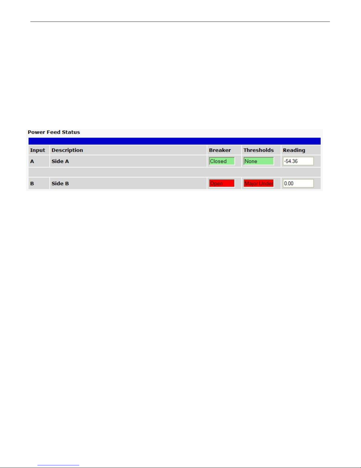
6.4.1 Power Feed Status (Operation)
From the blue Power Feed Status option under the Operation menu, you can check the status of your
input feeds.
55
The Inputs screen shows when you have an input alarm
For each feed, A and B, you will see:
· Breaker: the status of the breaker switch on the front panel of the RPS -- Closed or Open.
· Thresholds: Whether or not the input has set a threshold alarm -- Major Under, Minor Under, None,
Minor Over, or Major Over.
· Reading: the voltage input reading.
56
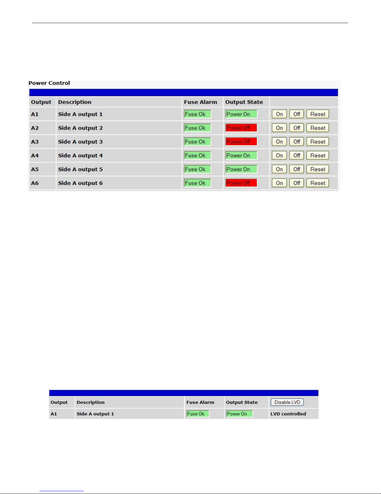
6.4.2 Power Control (Operation)
From the blue Power Control option under the Operation Menus, you can operate your power outputs
and view the status of each feed.
Turn power on and off and monitor fuse alarms from the Operation Menu > Power Control screen
Each output feed displays:
· Fuse Alarm: showing the status of the fuse associated with each feed.
o Fuse Ok, highlighted in green, indicates that the fuse is not blown
o Fuse Blown, highlighted in red, indicates that the fuse is blown
· Output State: indicating the current state of the power output.
o Power Off, highlighted in red, indicates that the output relay is off
o Power On, highlighted in green, indicates that the output relay is on
Note: The Output State reflects the state of the relay. Power may or may not be present at the output
depending on the state of the fuse.
The On, Off, and Reset buttons allow you to operate individual power feeds.
· On turns power on.
· Off turns power off.
· Reset temporarily turns power off before turning it back on again. Configure the length of time
between Off and On functions when issuing the Reset command by changing the Reset Time from
the Provisioning > Power Control screen.
If you have enabled the Low Voltage Disconnect feature for any of your unit's output feeds, you will
see LVD Controlled in the field where the control buttons would normally appear. You can override
LVD controled outputs by clicking the Disable LVD button.
The Low Voltage Disconnect (LVD) feature prevents manual control of your power outputs
Note: Take care when overriding power output feeds. If an output feed is off due to insufficient or high
voltage, re-enabling the output could result in damage to the equipment connected to the output.

6.4.3 Base Alarms (Operation)
This selection provides the status of the base alarms by indicating if an alarm has been triggered. Under
the State column, the status will appear in red if an alarm has been activated. The status will be
displayed in green when the alarm condition is not present.
The Default text for an alarm is "Alarm." This can be configured and user-defined with the On Set
condition under the Provisioning > Base Alarms menu.
57
The Operation > Alarms menu will tell you if any base alarms have been triggered

58
Control Relay Operation
ID
ID number for the control relay.
Description
Description for the NetGuardian's control relay defined in the Provisioning >
Controls menu.
State
Status of the control relay. Can either be Released or Latched.
Command
OPR - Latch the relay.
RLS - Release the relay.
MOM - Momentarily latch the relay, then automatically release the relay.
The duration of the latch is defined in the Provisioning > Controls menu.
6.4.4 User Controls (Operation)
Use the following rules to operate the NetGuardian's control:
1. Select Controls from the Operation menu.
2. Under the State column, you can see the current condition of the control.
3. To issue the control, click on a command (OPR - operate, RLS - release, or MOM - momentary)
View and operate control relays from the Operation > Controls menu
6.4.5 User Analogs (Operation)
The Operation > Analogs screen provides a description of each analog channel, the current reading,
the units being read, and alarm thresholds according to your settings.

Click on Analogs in the Operation menu to view the current channel readings.
6.4.6 Sensors (Operation)
The RPS AB6 supports up to 16 daisy-chained D-Wire sensors via its front-panel D-Wire input.
Sensors connected to the AB6 will appear on the RPS AB6's web interface. The background color of the
ROM field informs the user of the sensor's configuration state.
By default, the RPS AB6's first D-Wire sensor is used to monitor the internal temperature. When no
additional sensors are plugged in, ID #1 will refer to the RPS AB6's internal temperature. The internal
temperature sensor measures a range of -40° F to 180° F (-40° C to 82.2° C) within an accuracy of
about ± 2°.
Basic configuration for the RPS AB6's D-Wire temperature sensors can be accomplished from the
Provisioning > Sensors menu. From this screen, you can configure D-Wire sensors, select
notification devices, and set thresholds.
59
The Operation > Sensors menu
6.4.7 System Alarms (Operation)
The System Alarms option, in blue under the Operation heading, allows you to monitor the Remote
Power Switch's system alarms, the set of housekeeping alarms that report on the status of your
Remote Power Switch.
The System Alarms Monitoring screen

60
System alarms in a set state will show Set in a red field in the State column. When clear, alarm states
will read Clear on a light green background, as displayed in the example above.
Note: If you checked the Silence checkbox for an alarm on the Provisioning > System Alarms page,
its state will always show Clear on the Operation > System Alarms page. Checking the Silence box
prohibits system alarms from reporting via the web interface.

6.4.8 Event Log
Operation > Event Log
Control Relay Operation
Evt
The event number. The most recent event is displayed at the top.
Timestamp
The Date and Time the event occured.
State
The state of the alarm. Can be either "Alarm" or "Clear"
PRef
Point reference shows the display and point of the alarm.
Description
Alarm description.
Device Access
Description
61
The Event Log displays the log for all alarm events. The log has the following fields:
Device Access6.5
The Device Access options, listed in pink on the left side of the web interface, provide options for
generating reports, updating the Remote Power Switch's firmware, and rebooting the unit. Click any of
the options under Device Access to perform the desired action.
The control menu is located in the bottom left of the web interface

62
Option
Read
Reads a configuration file from the unit
Write
Commits all changes made in the web interface to the Remote Power
Switch's non-volatile memory
Initialize
Sets the unit's configuration to factory default values
Get Log
Opens the Remote Power Switch's event log in Notepad (or another plain text
editor).
Purge Log
Deletes the Remote Power Switch's event log history
Reboot
Reboots the Remote Power Switch
Updating Firmware6.6
To update the Remote Power Switch's firmware:
1. click Upload in the upper right corner of the web interface.
Click Upload in the upper-right corner of the web interface to upload new firmware
2. Click Browse to locate the firmware file for the Remote Power Switch
Browse for firmware, then click Upload to commit the firmware to the RPS
3. Click Upload to load the new firmware.
For the latest firmware, login to MyDPS, a link to which can be found in the upper-right corner of the web
browser interface. For problems and firmware-related questions, contact DPS Telecom support
(support@dpstele.com).

63
7
Here are answers to some common questions from Remote Power Switch users. The latest FAQs can
be found on the Remote Power Switch support web page, http://www.dpstelecom.com.
If you have a question about the Remote Power Switch, please call us at (559) 454-1600 or e-mail us at
support@dpstele.com
Q. How do I Telnet to the Remote Power Switch?
A. You must use Port 2002 to connect to the Remote Power Switch. Configure your Telnet client to
Q. What do the terms alarm point, display, port, and address mean?
A. These terms define the exact location of a network alarm, from the most specific (an individual
Frequently Asked Questions
connect using TCP/IP (not Telnet, or any other port options). For connection information, enter the
IP address of the Remote Power Switch and Port 2002. For example, to connect to the Remote
Power Switch using the standard Windows Telnet client, click Start, click Run, and type Telnet
<Remote Power Switch IP address> 2002.
alarm point) to the most general (an entire monitored device). An alarm point is a number
representing an actual contact closure that is activated when an alarm condition occurs. For
example, an alarm point might represent a low oil sensor in a generator or a open/closed sensor in a
door. A display is a logical group of 64 alarm points. A port is traditionally the actual physical serial
port through which the monitoring device collects data. The address is a number representing the
monitored device. The terms port and address have been extended to refer to logical, or virtual,
ports and addresses. For example, the Remote Power Switch reports internal alarms on Port 99,
address 1.
Q. When I connect to the Remote Power Switch through the craft port on the front panel it
either doesn't work right or it doesn't work at all. What's going on?
A. Make sure your using the right COM port settings. The standard settings for the craft port are 9600
baud, 8 bits, no parity, and 1 stop bit. Flow control must be set to none. Flow control normally
defaults to hardware in most terminal programs, and this will not work correctly with the Remote
Power Switch.
Q. How do I get my Remote Power Switch on the network?
A. Before the Remote Power Switch will work on your LAN, the unit address (IP address), the subnet
mask, and the default gateway must be set. A sample configuration could look like this:
unit address: 192.168.1.100
subnet mask: 255.255.255.0
Default Gateway: 192.168.1.1
Always remember to save your changes by writing to the NVRAM. Any modifications of the Remote
Power Switch's IP configuration will also require a reboot.
Q. Which version of SNMP is supported by the SNMP agent on the Remote Power Switch?
A. SNMP v1, v2c, and v3 are supported by the Remote Power Switch AB6.

64
8
DPS Telecom products are backed by our courteous, friendly Technical Support representatives, who
will give you the best in fast and accurate customer service. To help us help you better, please take the
following steps before calling Technical Support:
1. Check the DPS Telecom website.
2. Prepare relevant information.
3. Have access to troubled equipment.
4. Call during Customer Support hours. Customer support hours are Monday through Friday, from 7
Technical Support
You will find answers to many common questions on the DPS Telecom website, at http://
www.dpstelecom.com/support/. Look here first for a fast solution to your problem.
Having important information about your DPS Telecom product in hand when you call will greatly
reduce the time it takes to answer your questions. If you do not have all of the information when you
call, our Technical Support representatives can assist you in gathering it. Please write the information
down for easy access. Please have your user manual and hardware serial number ready.
Please be at or near your equipment when you call DPS Telecom Technical Support. This will help us
solve your problem more efficiently.
A.M. to 6 P.M., Pacific time. The DPS Telecom Technical Support phone number is (559) 454-1600.
Emerge ncy Assistance : Emergency assistance is available 24 hours a day, 7 days a week. For
emergency assistance after hours, allow the phone to ring until it is answered with a paging message.
You will be asked to enter your phone number. An on-call technical support representative will return
your call as soon as possible.

65
9
All Software and firmware used in, for, or in connection with the Product, parts, subsystems, or
derivatives thereof, in whatever form, including, without limitation, source code, object code and
microcode, including any computer programs and any documentation relating to or describing such
Software is furnished to the End User only under a non-exclusive perpetual license solely for End User's
use with the Product.
The Software may not be copied or modified, in whole or in part, for any purpose whatsoever. The
Software may not be reverse engineered, compiled, or disassembled. No title to or ownership of the
Software or any of its parts is transferred to the End User. Title to all patents, copyrights, trade secrets,
and any other applicable rights shall remain with the DPS Telecom.
DPS Telecom's warranty and limitation on its liability for the Software is as described in the warranty
information provided to End User in the Product Manual.
End User shall indemnify DPS Telecom and hold it harmless for and against any and all claims,
damages, losses, costs, expenses, obligations, liabilities, fees and costs and all amounts paid in
settlement of any claim, action or suit which may be asserted against DPS Telecom which arise out of
or are related to the non-fulfillment of any covenant or obligation of End User in connection with this
Agreement.
This Agreement shall be construed and enforced in accordance with the laws of the State of California,
without regard to choice of law principles and excluding the provisions of the UN Convention on
Contracts for the International Sale of Goods. Any dispute arising out of the Agreement shall be
commenced and maintained only in Fresno County, California. In the event suit is brought or an attorney
is retained by any party to this Agreement to seek interpretation or construction of any term or provision
of this Agreement, to enforce the terms of this Agreement, to collect any money due, or to obtain any
money damages or equitable relief for breach, the prevailing party shall be entitled to recover, in addition
to any other available remedy, reimbursement for reasonable attorneys' fees, court costs, costs of
investigation, and other related expenses.
End User License Agreement

66


Warranty
DPS Telecom warrants, to the original purchaser only, that its products a) substantially conform to DPS' published
specifications and b) are substantially free from defects in material and workmanship. This warranty expires two
years from the date of product delivery with respect to hardware and ninety days from the date of product delivery
with respect to software. If the purchaser discovers within these periods a failure of the product to substantially
conform to the specifications or that the product is not substantially free from defects in material and workmanship,
the purchaser must promply notify DPS. Within reasonable time after notification, DPS will endeavor to correct any
substantial non-conformance with the specifications or substantial defects in material and workmanship, with new or
used replacement parts. All warranty service will be performed at the company's office in Fresno, California, at no
charge to the purchaser, other than the cost of shipping to and from DPS, which shall be the responsiblity of the
purchaser. If DPS is unable to repair the product to conform to the warranty, DPS will provide at its option one of the
following: a replacement product or a refund of the purchase price for the non-conforming product. These remedies
are the purchaser's only remedies for breach of warranty. Prior to initial use the purchaser shall have determined the
suitability of the product for its intended use. DPS does not warrant a) any product, components or parts not
manufactured by DPS, b) defects caused by the purchaser's failure to provide a suitable installation environment for
the product, c) damage caused by use of the product for purposes other than those for which it was designed, d)
damage caused by disasters such as fire, flood, wind or lightning unless and to the extent that the product
specification provides for resistance to a defined disaster, e) damage caused by unauthorized attachments or
modifications, f) damage during shipment from the purchaser to DPS, or g) any abuse or misuse by the purchaser.
THE FOREGOING WARRANTIES ARE IN LIEU OF ALL OTHER WARRANTIES, EXPRESS OR IMPLIED,
INCLUDING BUT NOT LIMITED TO THE IMPLIED WARRANTIES OF MERCHANTABILITY AND FITNESS FOR A
PARTICULAR PURPOSE.
In no event will DPS be liable for any special, incidental, or consequential damages based on breach of warranty,
breach of contract, negligence, strict tort, or any other legal theory. Damages that DPS will not be responsible for
include but are not limited to, loss of profits; loss of savings or revenue; loss of use of the product or any associated
equipment; cost of capital; cost of any substitute equipment, facilities or services; downtime; claims of third parties
including customers; and injury to property.
The purchaser shall fill out the requested information on the Product Warranty Card and mail the card to DPS. This
card provides information that helps DPS make product improvements and develop new products.
For an additional fee DPS may, at its option, make available by written agreement only an extended warranty
providing an additional period of time for the applicability of the standard warranty.
Technical Support
If a purch aser believ es that a product is not operating in s ubs tantial co nformance with DPS' pub lished specifications or there
app ear to be defects in material an d workmans hip, the purch aser should con tact our techn ical su pport repres entatives. If the
prob lem can not be corrected over the telephone and the product and prob lem are covered by the warranty, the tech nical
supp ort represen tative will authorize the return of the produ ct for s ervice and provide shipping information . If the product is
out of warranty, rep air c harges will b e q uoted . All non-warrant y repairs receive a 90-day warrant y.

Free Tech Support is Only a Click Away
Need help with your alarm monitoring? DPS Information Services are ready to
serve you … in your email or over the Web!
www.DpsTele.com
Free Tech Support in Your Email: The Protocol Alarm Monitoring Ezine
The Protocol Alarm Monitoring Ezine is your free email
tech support alert, delivered directly to your in-box
every two weeks. Every issue has news you can use
right away:
Expert tips on using your alarm monitoring
•
equipment — advanced techniques that will save
you hours of work
Educational White Papers deliver fast informal
•
tutorials on SNMP, ASCII processing, TL1 and
other alarm monitoring technologies
New product and upgrade announcements keep
•
you up to date with the latest technology
Exclusive access to special offers for DPS
•
Telecom Factory Training, product upgrade offers
and discounts
To get your free subscription to
The Protocol register online at
www.TheProtocol.com/register
Free Tech Support on the Web: MyDPS
MyDPS is your personalized, members-only online resource.
Registering for MyDPS is fast, free, and gives you exclusive
access to:
• Firmware and software downloads and upgrades
• Product manuals
• Product datasheets
• Exclusive user forms
Register for MyDPS online at
www.DpsTele.com/register
(800) 622-3314 • www.DpsTelecom.com • 4955 E. Yale Avenue, Fresno, California 93727
 Loading...