

Page 1
Product Summary
June 14, 2002 UM026.14100
www.dpstele.com (800)622-3314
User Manual
NIA Card
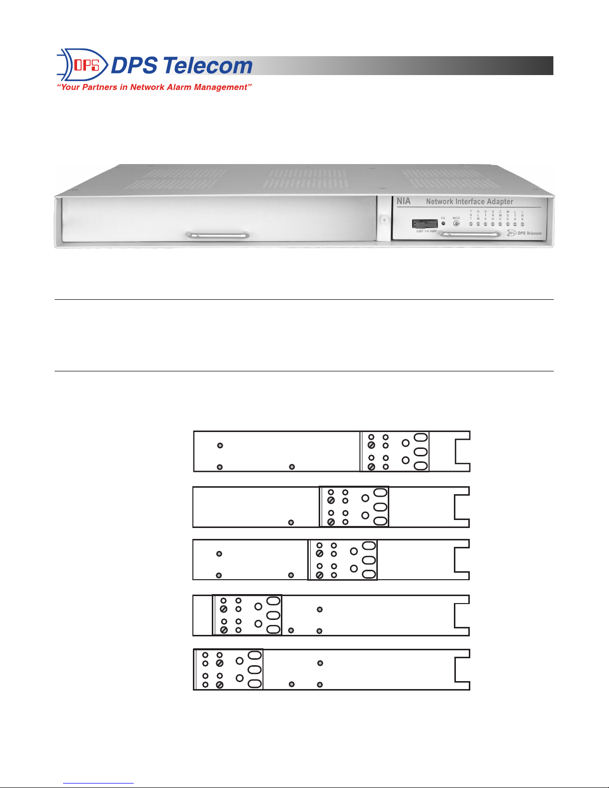
Figure 1 - NIA card with blank KDA shelf.
Overview
DPS’ Network Interface Adapter fits in the expansion card slot of the KDA shelf. It interfaces directly to an Ethernet
10BaseT network using SNMP protocol.
The unit is easy to install, with connectors for all serial and LAN ports and it
mounts quickly in either 19" or 23" equipment racks while occupying only one rack unit of space.
Mounting Instructions
The unit can be mounted in a 19” or 23” rack by using the reversible rack ears for either size (provided). Several rack ear
locations are available. Attach the ears for your rack using either the 7”, 5 1/2”, 5”, 1/2”, or 0” (flush mount) projection. See
the figure below for mounting options.
Figure 2 - The KDA offers several mounting options.
19" or 23" Rack/
7" Projection
19" or 23" Rack/
5-1/2" Projection
19" or 23" Rack/
5" Projection
19" or 23" Rack/
1/2" Projection
19" or 23" Rack/
Flush Front
NOTE: Use wide ears for 23"
SIDE VIEW REAR
Page 2
June 14, 2002 UM026.14100
www.dpstele.com (800)622-3314
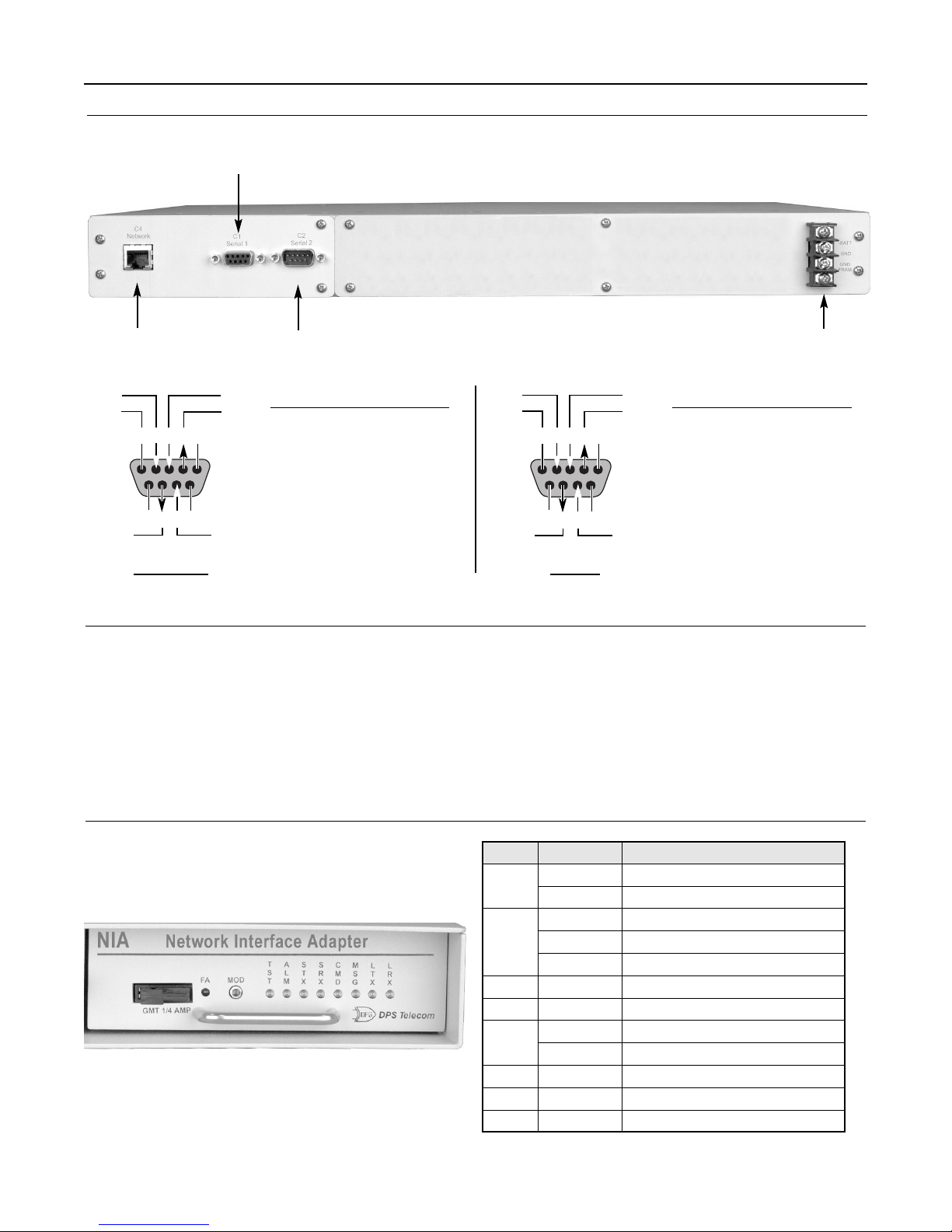
Rear Panel Connections
10BaseT
LAN Connection
Primary
Interface
(Male DB9)
Configuration
Interface
(Female DB9)
Power
Block
Power Connection (Main KDA Shelf Only)
1. Remove the fuse from the front panel and turn off the power supply when connecting the power from the main feed.
2. Connect a -48VDC line to the -BATT terminal and the ground to the GND terminal.
3. Turn on main power with the fuse still removed.
4. Connect the black common lead of a volt meter to ground and the red lead to -BATT. The Meter should read the battery
level (-43 to -53VDC). If not, check your power supply
5. Do not re-insert the fuse (powering up the unit) until all other connections have been made.
Note: Observe polarity when connecting battery leads. If using the -48VDC red/black cables supplied with the unit, connect black to
GND and red to -BATT. Standard gauge is 20AWG, which varies from 18-24AWG.
5 4 3 2 1
9 8 7 6
DSR
GND
RX
TX
RTS
CTS
Female
PIN# Signal Description
1
2
3
4
5
6
7
8
9
NC
TX
RX
DSR
GND
NC
CTS
RTS
NC
Not connected
Transmit data
Receive data
Data set ready
Ground
Not connected
Clear to send
Request to send
Not connected
1 2 3 4 5
6 7 8 9
DSR
GND
RX
TX
RTS
CTS
Male
PIN# Signal Description
1
2
3
4
5
6
7
8
9
GND
DSR
RX
TX
NC
NC
RTS
CTS
NC
Ground
Data set ready
Receive data
Transmit data
Not connected
Not connected
Request to send
Clear to send
Not connected
NIA LED Display
Tbl. 1 - NIA LED Descriptions.
LED Condition Description
TST
ALM
STX
SRX
CMD
MSG
LT X
LRX
Flash GN
RD
GN
RD
Flash RD/GN
Flash GN
Flash RD
Flash GN
Flash RD
Flash GN
Flash GN
Flash RD
Unit operating normally
MOD switch pressed
No standing alarms
Standing alarms exist
Unreported COS alarms exist
Serial port transmitting
Serial port receiving
SNMP Get/GetNext
SNMP Set
Trap
LAN port transmitting
LAN port receiving
Page 3

June 14, 2002 UM026.14100
www.dpstele.com (800)622-3314
NIA Configuration
1. Before configuration can begin, power must be connected to the main KDA shelf.
2. Connect a DB9 download cable to the female DB9 C1.
3. Connect the other end of the DB9 cable to a PC running terminal emulation software.
4. Set your computer’s serial port to match the NIA card’s default data rate and word format settings (9600 N, 8, 1). In
your terminal emulation software, be sure to set the Flow control to “None.”
5. Press and hold the “MOD” button on the front panel of the NIA card. As you hold the button down, insert the fuse into
the front panel. Continue holding the “MOD” button until the front panel LEDs stop flashing (approx. 10 seconds).
6. When a connection is established, hit any key to bring up the first configuration menu.
IP Address
1. To edit the IP Address information, type “E” for E)dit and then “I” for I)P Parameters.
2. Enter the IP Address, the Subnet Mask, and Default Gateway.
NIAT v2.2F Configuration
E)dit W)rite e(X)it ? E
I)P Parameters P)ass-thru Port ? I
Unit Address :126.010.230.102
SubNet Mask :255.255.255.000
Default Gateway :126.010.230.001
U)nit Address S)ubnet Mask D)efault Gateway ?
Pass-thru Port
1. To edit the Pass-thru Port information, type “E” for E)dit and then “P” for P)ass-thru Port.
2. Type “P” to set the P)rotocol (either Telnet or UDP).
3. Type “B” to set the B)aud rate (300, 600, 1200, 2400, 4800, 9600, 19200, 38400, 57600, or 115200).
4. Type “M” to set the Pro(m)pt configuration. This will toggle between yes and no. Yes means a prompt will appear
when you connect to the NIA and no means that no prompt will appear.
NIAT v2.2F Configuration
E)dit W)rite e(X)it ? E
I)P Parameters P)ass-thru Port ? P
Protocol :UDP
Baud Rate :9600
Prompt :YES
P)rotocol B)aud Pro(m)pt ?
Writing to the NIA
1. To write the configuration information to the NIA, type “W” for W)rite from the main menu.
NIAT v2.2F Configuration
E)dit W)rite e(X)it ? W
Page 4
“Dependable, Powerful Solutions
that allow users to monitor larger,
more complicated networks with a
smaller, less trained staff”
“Your Partners in Network Alarm Management”
www.dpstele.com
4955 E. Yale Avenue • Fresno, CA 93727
(559) 454-1600 • (800)622-3314 • (559) 454-1688 fax
 Loading...