

Page 1
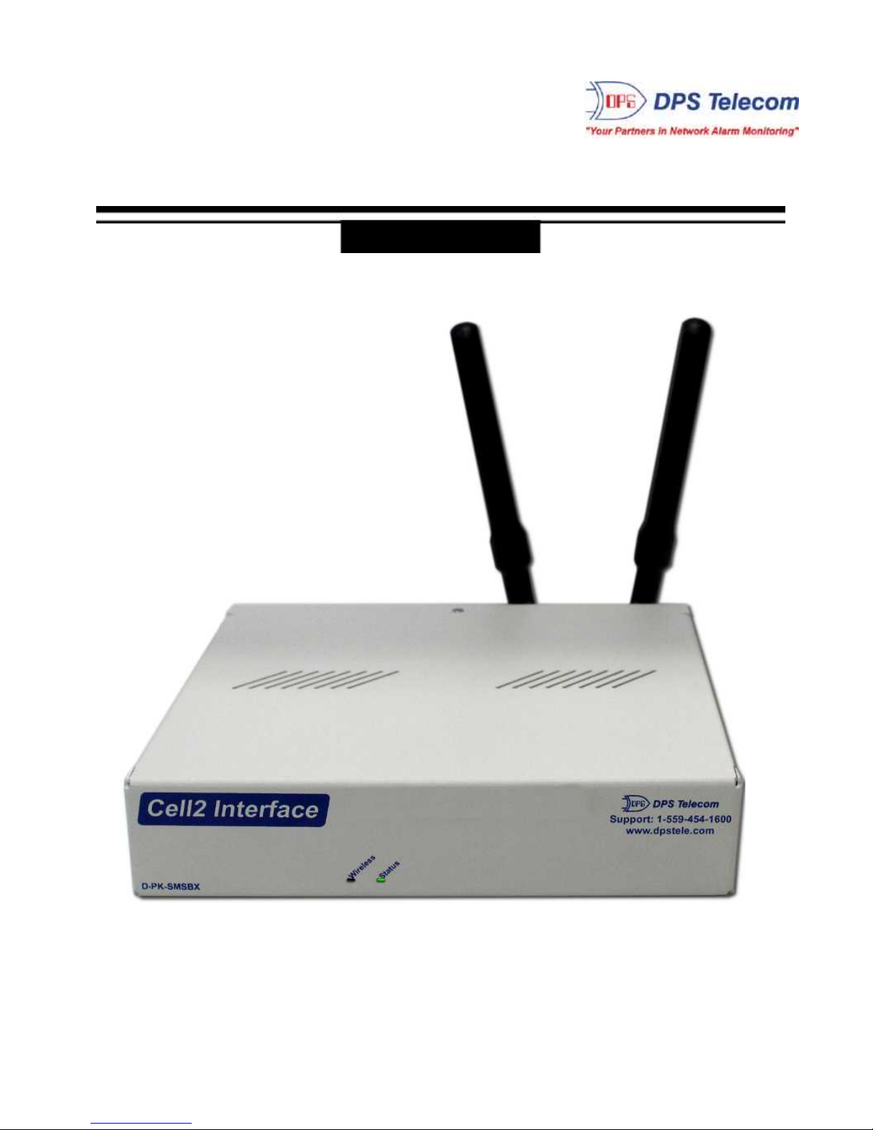
Cell2 Interface
USER MANUAL
D-PK-SMSBX-12021
Visit ou r website at www.dpstelecom.com for the latest PDF manual and FAQ s.
October 27, 2017
D-UM-SMSBX-12021 Firmware Version 1.0A
Page 2

Revision History
October 27 , 2017 Initial Release
This document contains propri etary information which is protected by copyright. All r ights are reserved. No part of this
document may be photocopied without pri or w ritten consent of DPS Telecom.
All software and manuals are copyri ghted by DPS Tel ecom . Said software and m anuals may not be reproduced, copied,
transmi tted or used to make a derivative work, by either mechanical, el ectronic or any other means in whole or in part, without
prior wr itten consent from D P S Telecom, except as required by United States copyright laws.
© 2017 DPS Telecom
Notice
The material in this manual is for inform ation purposes and is subject to change without notice. DPS Telecom shall not be
liable for errors contained herein or consequential damages in connection with the furnishing, perform ance, or use of this
manual.
Page 3

Contents
Visit our w ebsite at www .dpstelecom.com for the latest PDF manual and FAQs
Cell 2 I nte rfa ce Ove rvi ew1 1
Specifications2 2
Shippi n g Li st3 3
Optional Acc essories3.1 4
Installation4 5
Tools Needed4.1 5
Mounting4.2 6
Cell 2 I nte rfa ce Fron t Pane l5 7
Cell 2 I nte rfa ce Ba ck Pane l6 8
Power Connection6.1 9
LAN Connect ion6.2 10
Craft Port (USB)6.3 11
Back P anel LEDs6.4 12
GPRS/CDMA W ireless Modem6.5 13
Quick Start: How to Connect to the Cel l 2 I nte rfa ce7 14
... via Craft Port7.1 14
... via LA N7.2 21
Wi reless Modem Activation8 22
TTY Interface9 23
Logging on to the Ce l l 2 In te rfa ce10 24
Provisioning11 25
System11.1 25
User Profiles11.2 26
Ethernet11.3 27
RADIUS11.4 28
Serial Port11.5 29
SNMP11.6 30
Notifications11.7 31
Email Notifications11.7.1 32
SNMP Traps11.7.2 34
System Al arms11.8 36
Device Groups11.9 37
Devices11.10 38
Timers11.11 39
Date and Time11.12 40
Monitor12 41
Page 4

System Al arms12.1 41
Devices12.2 42
Event Log12.3 43
Stats12.4 44
Device Access13 45
Firmware Upgra de14 46
Reference S ection15 47
Display Map15.1 47
SNMP Manager Func t ions15.2 49
SNMP Granular Trap P ackets15.3 50
Frequently Aske d Questi ons16 51
General FAQs16.1 51
SNMP FAQs16.2 52
Techni ca l S up port17 53
End User Lice n se Agree me nt18 54
Page 5
1
1
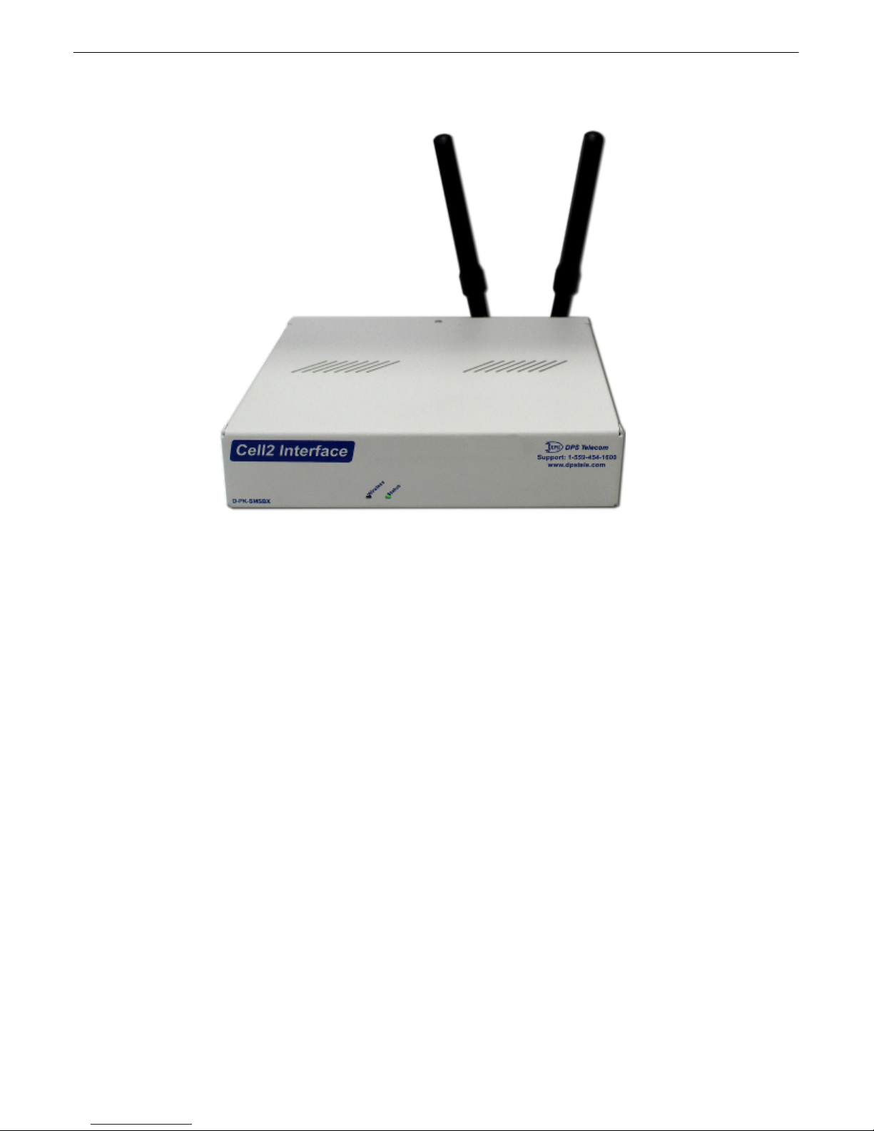
Cell2 Interface Overview
Receive alarms via GSM or CDMA with the Cell2 I nterfac e.
Wi reless alarms to your master sta tion
The Cell2 Int erface allows y ou to utili z e wireless RTUs with y our alarm master station without paying for an
expensive third-party data provider or opening a hole in your firewall to receive alarms on y our mast er s tation.
Wireless RTUs used to create a lot of unwanted hassle. To send alarms t o y our master st ati on, y ou had to pay
your cellular carrier or a third-party data provider for a static IP address. Then, you had t o punch a hole in y our
firewall to get that data back into y our network - a sec urity ris k s ome IT departments si mply weren't willing to tak e.
Wit h t he Cell2 Interface, you can now report alarms to your T/ Mon or SNMP mast er st ati on without paying your
cellular carrier for a static IP or creating a security breach. Alarms c an be reported via SMS direct ly t o y our master
station.
How i t W orks
Rather t han reporting alarms over IP, simply c onfigure y our wirel ess Cell2 to send SMS alarm information to the
Cell2 Interface. The Cell2 Interface then forwards t he alarm information to T/Mon (or other SNMP manager) when
polled over LAN using DCPx protocol.
Reporting alarms via SM S rather than IP allows y ou to bypass t he traditional hassles of wireles s IP-based alarm
reporting. One Cell2 Interface can support alarms for up to 253 Cell2 Devices, allowing you to cheaply and eas il y
deploy wireles s RTUs or est ablish a backup alarm-reporting path over wireless devic es.
Upgrade d We b Brow ser
The overhauled web interface boasts s everal time-savi ng new tools. You'll also notice the impressive s peed boost.
Menus load nearly instantly and the entire interface is very responsive.
Page 6

2
Hardware
Dimensions:
1.7 20" H x 8.126" W x 7.146" D
Mounting:
Short Rack (single ear ) o r Wall Mo unt
Weight:
1 lb. 8 oz
Power I nput:
-48VDC (-36 to -60
VDC)
3
Current
Draw:
100mA @ 48 VDC
200mA @ 24 VDC
Fuse:
3/ 4 Amp GMT Fuse
Visual Interfaces:
2
Front Panel LED s
10 B ack
Panel LED's
1
Hardware Int erfaces :
1 R J45 10/100BaseT E thernet
1 USB C raf t Port
Discrete A larm Inputs:
0
2
Discrete Alarm L ength:
N/A
Analogs:
0
Input Range:
N/A
4
An alog Accuracy:
N/A
Control O utputs:
0
Max Voltag e:
N/A
Max Current:
N/A
Operating Tem p:
32° t o 140°F ( 0° t o 60°C)
1
Indu strial Op erating Tem p:
-22° to 1 58°F (-30° to 70° C)
Operating Humidity :
0% to 95% non-cond ensing
MTBF:
60
Years
RoHS:
RoHS 5 App roved
Software
Downloadable Firmware:
Yes
Built-in Web I nterface:
Yes
Br owser Su pport :
IE9, IE10, Firefox, Chrom e, etc.
Protocols:
DCPx, TELNET, HTT P, Email
SNMP S up port:
v1, v 2c, v 3
1
D-Wir e Senso r Support:
No
Ping Ala rms:
N/A
OS S upp ort:
Windows 95, 98, NT, ME, XP, 2000, V ist a, 7
32/64bit
Note:
1
Valid if hardware option is included.
2
Mini mum l engt hs
de termined wit h TT L (5V), 24AWG, dry contact
ala rm s. Actual d istance may vary.
3
Current m easured a t r at ed vo ltage wit h all co n tro l s latched a n d all
alarms triggered.
4
See analog sect io n in manual for detailed analo g accura cy br eak down.
* This e quipment has been tested and found t o co mply wi th the limits for a Cl ass A digita l de vice, p ursuant to p art 15 of the FCC Rules. Th ese l imit s are
designed to provide re asonable protection against harmf ul interference when the equipment is operated in a commercial environment. This equipme nt
generates, uses, and can radiate r adio f requency energy and , if n ot installed a nd used in a ccorda nce with the instruction manual, ma y ca use h armful
interference to radio communications. O pera tion of this equ ip ment in a residential ar ea is likely t o caus e harmful interference in whi ch case the user will
be required to cor rect t he in ter ference at hi s o wn expense.
2
Specifications
Page 7
3
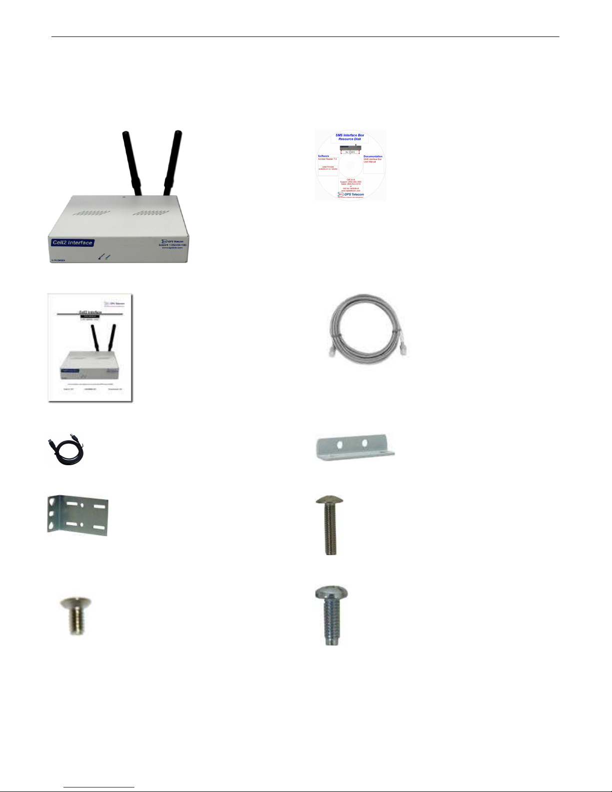
Cell 2 I nte rfa ce
D-PK-SMSBX-12021
Cell 2 I nte rfa ce Re source CD
Cell 2 I nte rfa ce User Man ual
D-UM-SMSBX-12021
14 ft. Etherne t Cab l e
D-PR-923-10B-14
6 ft. USB Cra ft Port Cable
D-PR-046-10A-06
Wall M ount Bracke t - QTY 2
D-CS-532-10A-05
Short Rack Ear
D-CS-325-10A-00
Me tric Rack Scre ws - QTY 4
2-000-80750-03
Wall m o unt bra cke t chassis screw s - QTY 4
2-000-60250-01
Four Stan dard Rack Scre ws - QTY 4
1-000-12500-06
3
Please make s ure all of t he following items are included with y our Cell2 Interface. If parts are miss ing, or if you ever
need to order new parts, please refer to the part numbers listed and call DPS Telecom at 1-800-622-3314.
Ship p i n g L i st
Page 8

4
3/8" Ear Scre ws - QTY 8
1-000-60375-05
Locking Powe r Conne ctor Pl ug for Main
2-820-35102-00
Pa ds - QTY 4
2-015-00030-00
3/4 Amp GMT Fuse - QTY 2
2-741-00500-00
Option al Acces sories3.1
Long e ar, 19" rack
D-CS-325-10A-08
Page 9
5
4
Installation
Tools Needed4.1
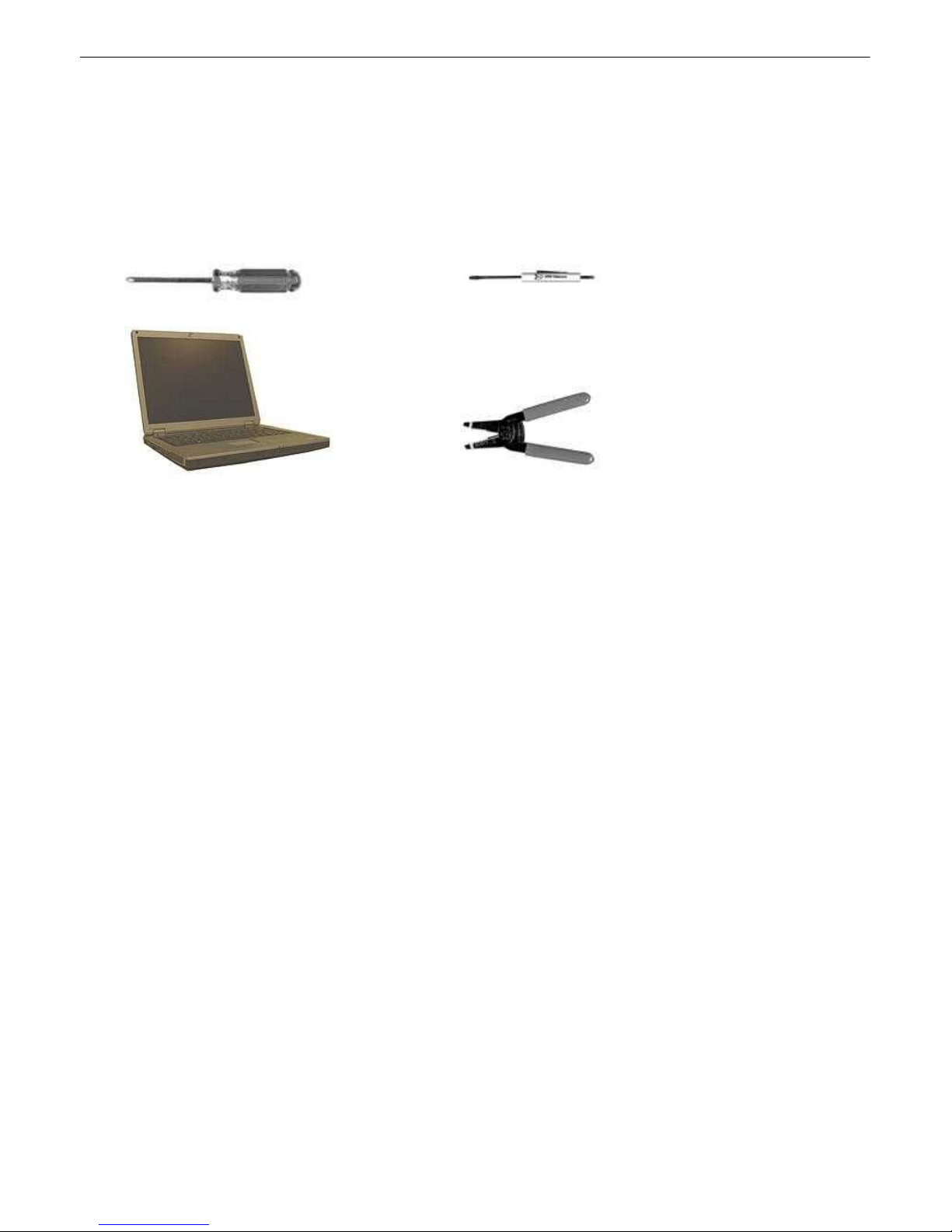
To install the Cell2 Interface, you'll need the following tools. NOTE: To install the Cell2 Int erface in one of the wall-
mount configurations, y ou will also require a wrench or driver capable of tightening 3/8" hex nuts.
Phil l i ps No. 2 Screw dri ver Small S ta nd ard No. 2 Screwdri ve r
PC with terminal emulator, Wi re Strippers
such a s HyperTe rm i nal
Page 10
6
Mounting4.2
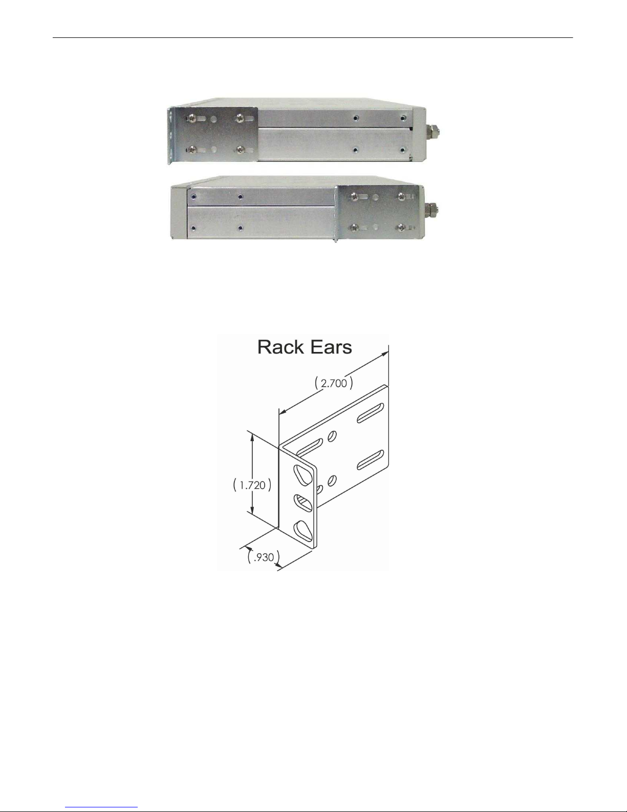
The Cell 2 Interfac e can b e f lus h or rear-mounted
The compact Cell2 Interface occ upies only half the width of a st andard rack unit . Only one rack ear is supplied with
the Cell2 Interface, and the rack ear can be mounted on the left or right side of t he unit. The Cell2 Interface mounts
in a 19" or 23" rack , and can be mounted on the right or left, in t he flush-mount or rear mount loc ations, as s hown in.
The rack ears c an be rotated 90° for wall mounting or 180º for other mounting options.
Use the included wall m ount bracket t o mount the Cell2 Interface vertically on the wall.
Wall -Mountin g I nstructions
The rack ears c an be rotated 90° for wall mounting or 180º for other mounting options (not shown).
1. Depending on your order options, you will can attach wall-mount flanges to both sides of the unit in one of two
ways:
a. P l ace t he flange over the prot ruding screws and fast en it t o t he 3/8" hex nuts provided.
b. OR Fast en the flange to t he Cell2 Interface with two of the 6/32 screws provided. (NOTE: Sc rews longer than
those provided m ay contact t he internal component s of the unit, adversely affec t ing its normal operat ion.)
2. After fl anges have been att ached to the Cell2 Int erface, mount the unit in the des i red location with two screws
through each flange.
Page 11
7
LED
Status
Description
Wireless
Off
No wireless ac t ivity
Blinki ng Red/Green
Wireless ac t ivity/t ransmis sion
Red
Modem error. See sy stem alarms.
Status
Blinki ng Green
Application is running
Blinki ng Red
Bootloader is running
5
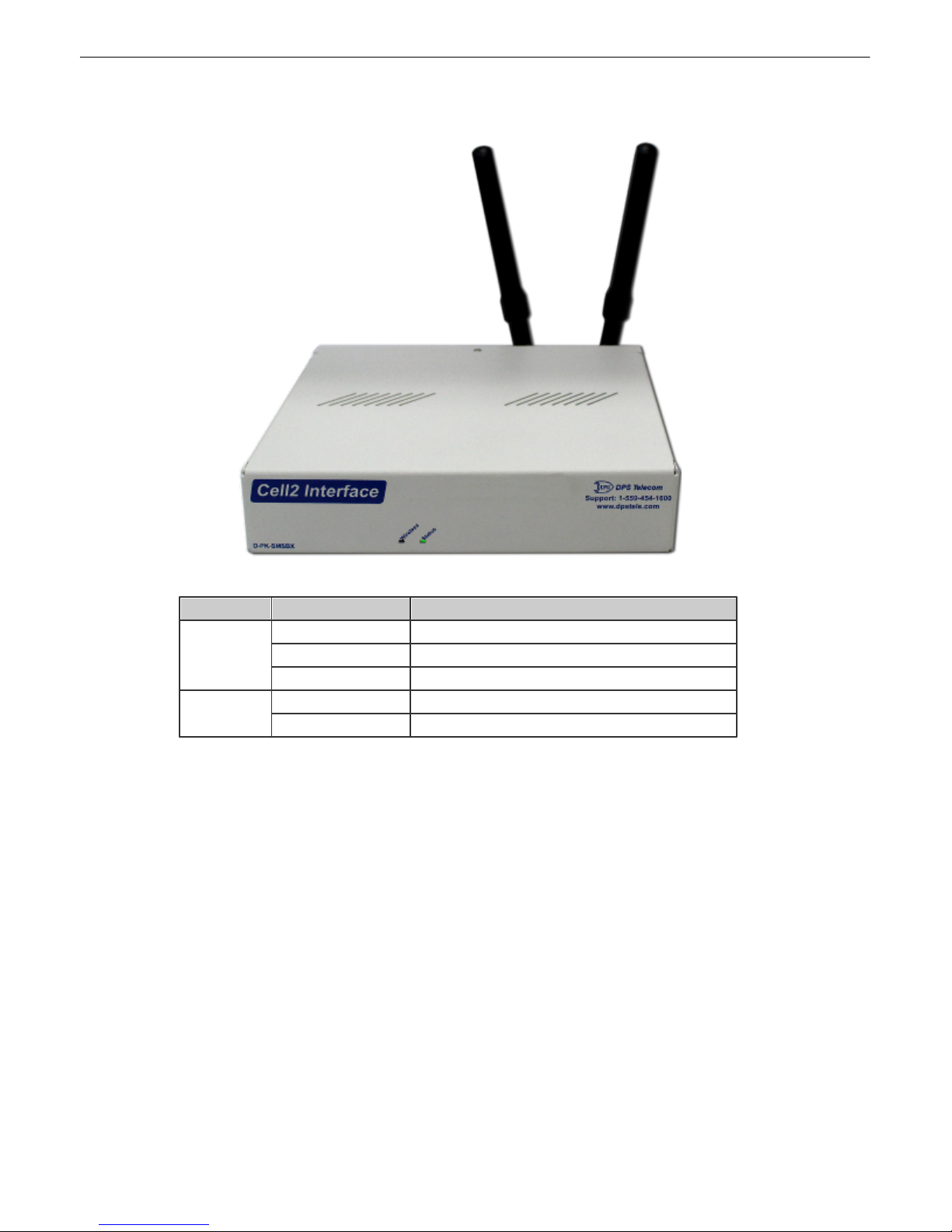
Cell2 Interface Fron t Panel
Cell2 Interface front panel
Page 12
8
6
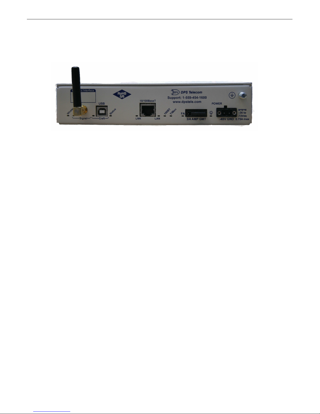
Cell2 Interface Back Panel
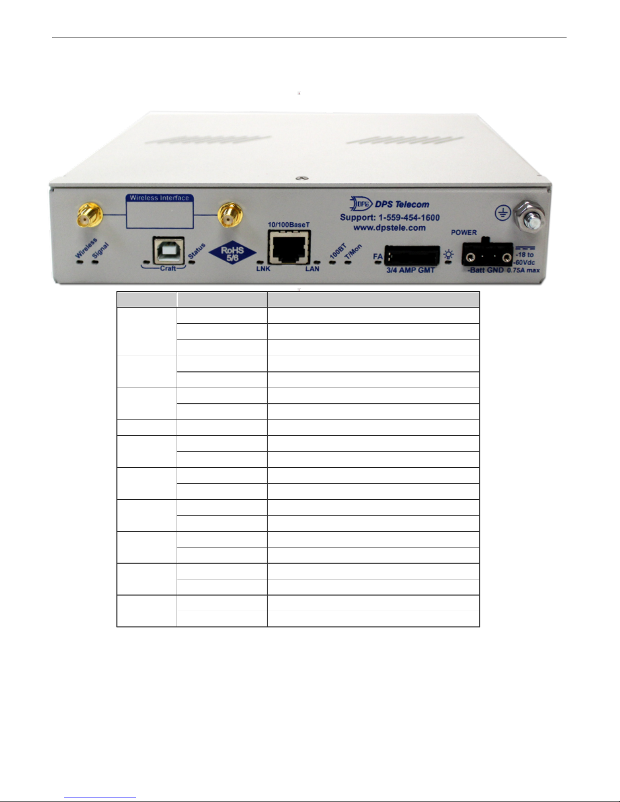
Cell2 Interfa ce b ack pane l conn ectio ns
Page 13
Power Conn ection6.1
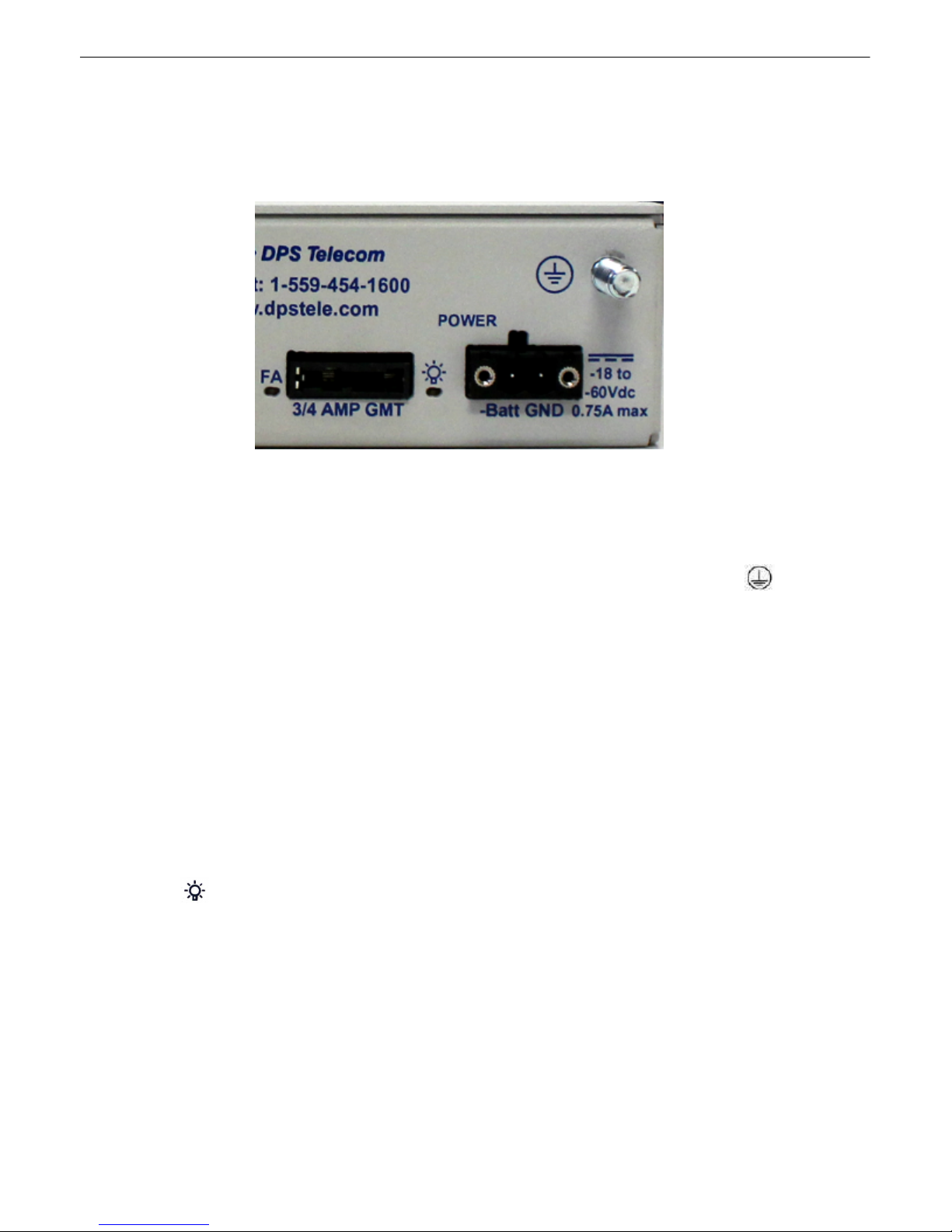
The Cell2 Int erface is powered by a single RIA power connec t or.
RIA power connector
Note: A l ways use s afe power practices when making power connections. Be s ure to remove fuses from the fus e
distribution panel, as well as the back of the Cell2 Interface, before m aking your power c onnecti ons.
9
To connect the Ce l l 2 I nte rfa ce to a pow er supply:
1. Us e the grounding lug to connect the unit to earth ground. The grounding lug is next t o t he sy mbol .
2. Insert the eyelet of the eart h ground c able between t he two bolts on the grounding lug (Ground cable not
included).
3. Insert a battery ground into the power connector plug's right terminal and tighten the screw.
4. Insert a battery lead to the plug' s left terminal and tighten its screw.
5. Insert fuse into the fus e dis t ribution panel.
6. Check the power status LED for polarity.
7. M easure voltage. Connec t t he black cable onto the ground connector of your DVM and red cable onto the other
connector of your DVM. The voltmeter should read between -36 VDC and -72 VDC.
Note: If the voltage does not read bet ween -36 V DC and -72 VDC, stop immediately .
8. Insert the local fuse into the power fuse slot. The power plug can be ins erted into the power connector only one
way to ensure the corre ct polar ity.
Note: Th e nega tive vo ltage terminal is on the left and the GND t erminal is on the right.
9. V erify that t he LED is lit . To confirm t hat power is correctly connected, the front panel stat us LE D will flash
RED and GREEN, indicating that the firmware is booting up.
Page 14
10
LAN Conn ection6.2
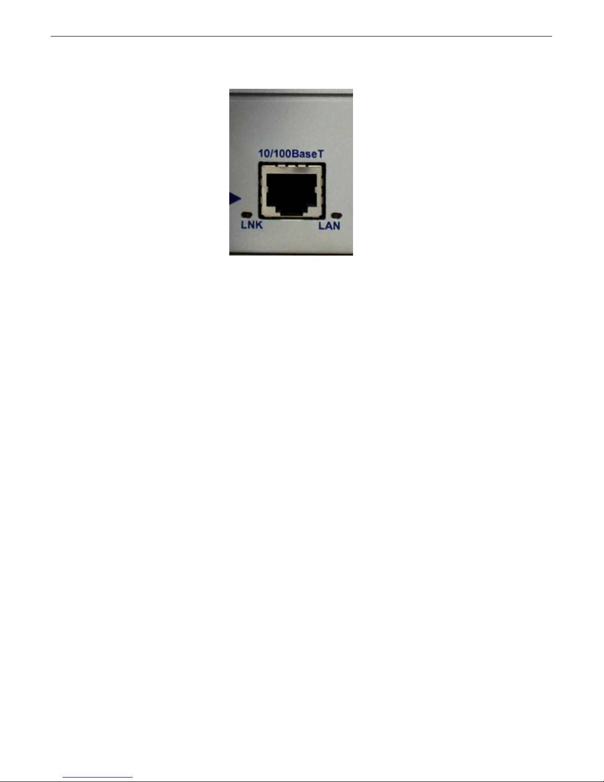
To c onnect t he Cell2 Interface to LAN, insert a standard RJ45 Ethernet cable into the 10/ 100BaseT Ethernet port on
the back of the unit. If the LAN connection is OK, t he LNK LED will l i ght S OLI D GREEN.
Page 15
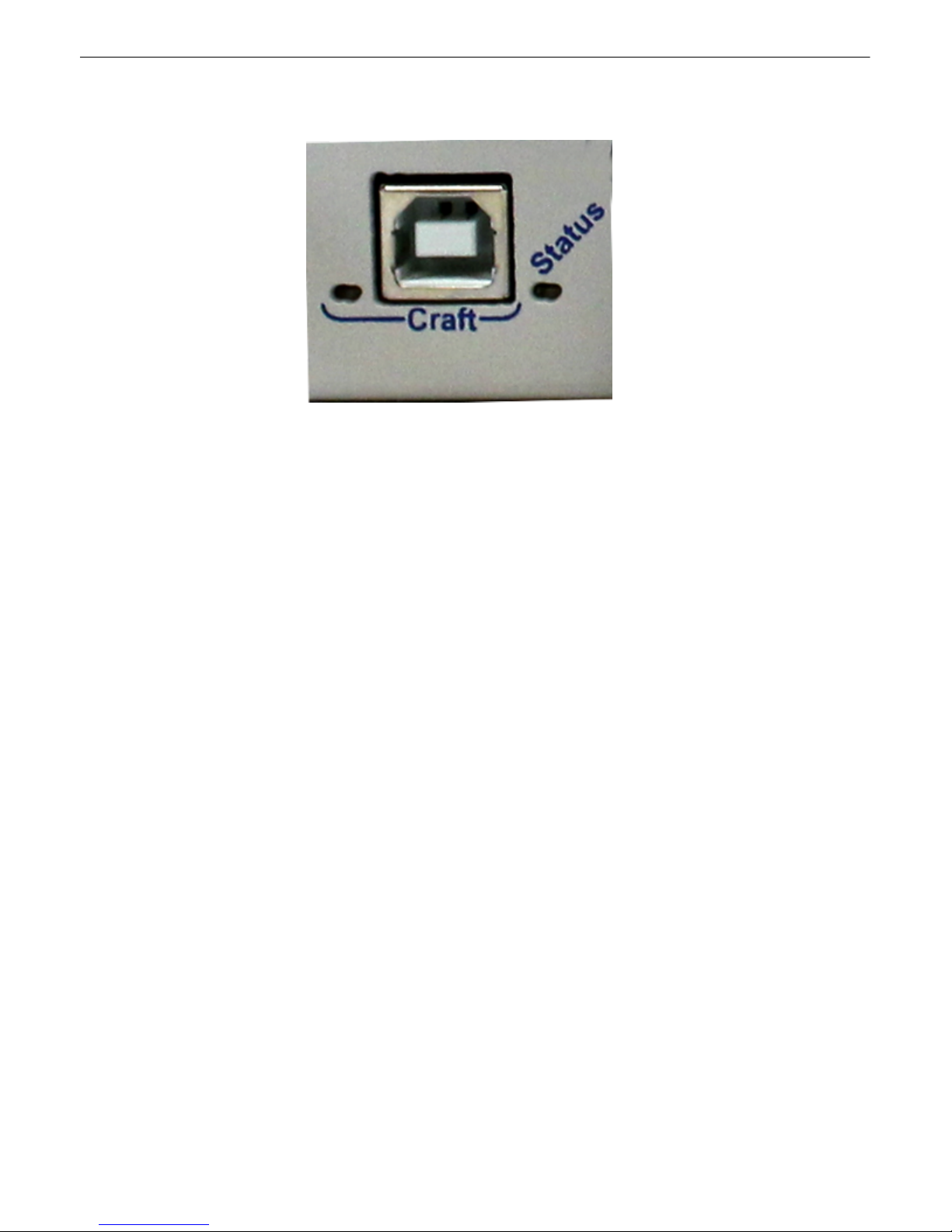
Craft Port (USB)6.3
Use the back panel craft port to connect t he Cell2 Int erface to a PC for onsite unit configurat ion. To use the craft
port, connect the incl uded USB download cable from y our PC to the craft port .
11
Page 16
12
LED
Status
Description
Wireless
Off
No wireless ac t ivity
Blinki ng Red/Green
Wireless ac t ivity/t ransmis sion
Red
Modem error. See sy stem alarms.
Signal
Blinki ng Green
Application is running
Blinki ng Red
Bootloader is running
Craft
Blinki ng Green
Data Transmitt ed over Craft
Blinki ng Red
Data Rec eived over Craft
Status
Blinki ng Green
Everything is running
LNK
Solid Green
Ethernet connection establis hed
Off
No ethernet c onnection
LAN
Blinki ng Green
Communication across LAN
Off
No communication across LAN
100BT
Green
10/100BaseT LAN connection
Off
10BaseT LAN c onnection
T/Mon
Off
No activity
Green
T/ M on is polling device
FA
Red
Fuse blown indic at or
Off
Fuse OK
Power
Green
When power is present
Off
No power is present
Back Panel LEDs6.4
Back Panel LED Des c riptions
Page 17
GPRS/CDMA Wirele ss Modem6.5
+
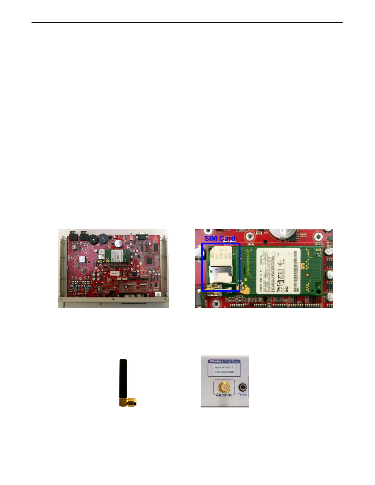
The Ce ll2 Interfa ce i s available with a n optio nal GPRS/GSM or CDMA wireless modem, allowing you to
repo rt alarms from your remote sites witho ut LA N or di alup conn ections vi a SM S notificati ons over a
cellul ar band .
On the back of your Cell2 Interface with a wi reless modem, you'll see th e anten na node protrud e from
the b a ck pa n e l of th e un i t an d a la b e l ab o v e th e no d e in d i cati n g the ty p e o f mode m - GPRS/G SM
(Sprin t) or CDM A (Ve rizon) - instal le d in yo ur un i t.
Note: You cann ot access to your Cell2 Interf ace's web or TT Y int erfaces over cell ular connection. Y ou
must confi gu re the un it vi a the back-sid e craft connectio n or ov e r LAN.
Note: If yo ur Cell2 Inte rf ace model is CDMA enabled: The Electronic Seria l Number (ESN) will be
locate d on the back of the unit (You will not need to open up the unit to retrieve the ESN). Your
cellular carrier will need t his number to e nable your Cell 2 In t erface's wireless modem.
To Enable Wireless Alarm Reporting:
1. Disconnect power connections to the Cell2 Interface
2. Remove the 3 screws on the bottom of th e Cell2 Inte rf ace ne ar the front pane l.
3. Remove th e 3 screws on the top o f th e Cel l 2 Interfa ce ne ar th e ba ck pa n el .
4. Remove the Cell2 Interface's cover.
5. If your Cell 2 In t erface model i s GPRS/GSM enabled: Insert a SIM card in the ava ilable modem slot.
13
Open your Cell2 Interface to insert your SIM card or take down your ESN
6. Rep lace the Cel l2 I nterface's top-cover and fa sten it to th e Cell2 Inte rf ace with t he 6 screws you
remove d in steps 1 an d 2.
7. Attach the anten na that came with your Cell2 Interface (2-901-00 802-01) t o the no de labeled
Antenna, and tig h te n the nu t to fa sten it to th e Cell 2 Interf ace.
The Antenna attaches to the Cell2 Interface's back panel to facilitate cellular signal reception
Page 18
14
1. Th e simple st way to connect to t he Cell2 Interface is over a physical cable connectio n between
you r PC's U SB port an d th e un it 's USB craft port. Note: You must be con nected vi a craft port or
Telnet to use the TTY interface. Make sure you are using a standard A-B USB cable (this same
cable is commonl y used for USB print ers) to make a USB craft port connection. We'll be u sin g
HyperTermin al to connect to the unit in the followin g example - howeve r, most te rminal-emulating
prog rams are al so compatible.
Note: The following image s di spl ay the setup process done i n Windows XP.
The f ollowin g steps will occur the first time any DPS USB equipment is used on this PC. If you've
used a di ff ere n t DPS U SB de v ice be fo re an d ha v e instal l e d the DPS USB dri v e rs, the n s kip to Step
9.
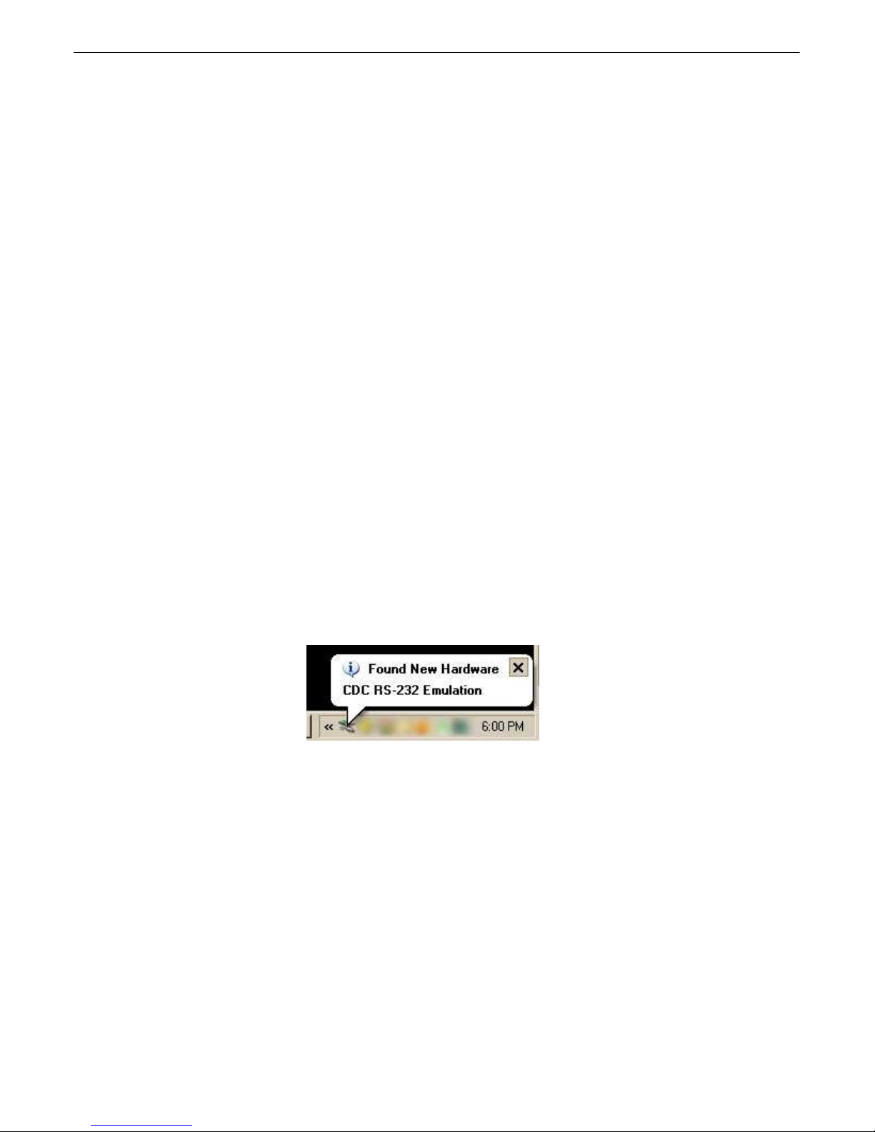
When yo u first connect the Ce ll2 Interfa ce to your PC v ia USB, a "Found New Hardware" message
will appear:
1. Click the "Foun d New Hardware" message/icon t o launch the "Fou nd New Hardware Wizard".
7
Most us ers find it easiest t o give the unit an IP address , s ubnet and gat eway through the front craft port (TTY
interfac e) to st art. Once t hese set t ings are saved and you reboot the unit, y ou can acc es s it over LAN to do the res t
of your databasing via the Web Browser interface.
Alterna tive option: You can sk i p the TTY interface by using a LAN crossover cable direc t ly from y our PC to the
Cell2 Interface and access its Web Browser. See Section Cell 2 Interface We b Browser.
Quick Start: Ho w to Con n ect to the Cell2 Interface
...via Craft Port7.1
Page 19
15
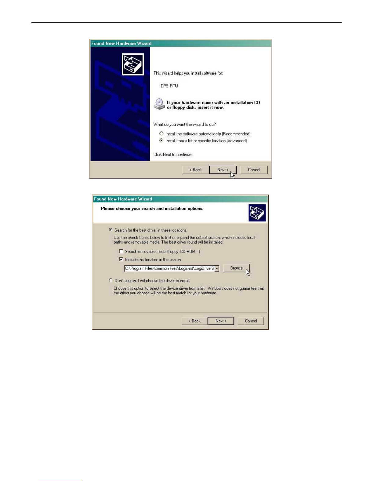
2. Select "Instal l from a list or specifi c lo cation (A dvanced)"
3. Click "Next >"
4. Select "Search for the best drive r in these locations."
5. I nsert Cel l2 I nterface Resource Disc (CD) into y our PC.
6. Click "Bro wse"
Page 20
16
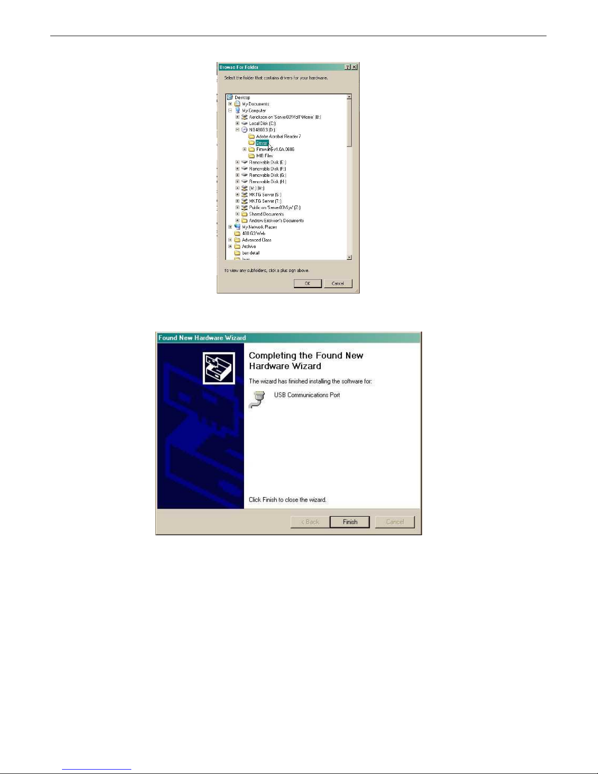
7. Select th e "Driver" folde r of your Cell2 Interfa ce Resou rce Disc Disc (CD) and cli ck "OK"
The f ollowin g message will conf irm instal lation of a new "USB Communicati ons Port"
8. Click "Finish" to clo se the Wizard.
Now that the drive r has been i nstalled, a n ew COM port is be ing emula t ed on y our PC. Before using
hyperterminal, you must confi rm the ident ity of that new COM port (COM1, COM2, COM3...) in t he
Windows Device Manager.
Page 21
17
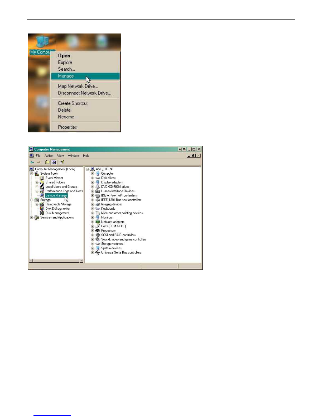
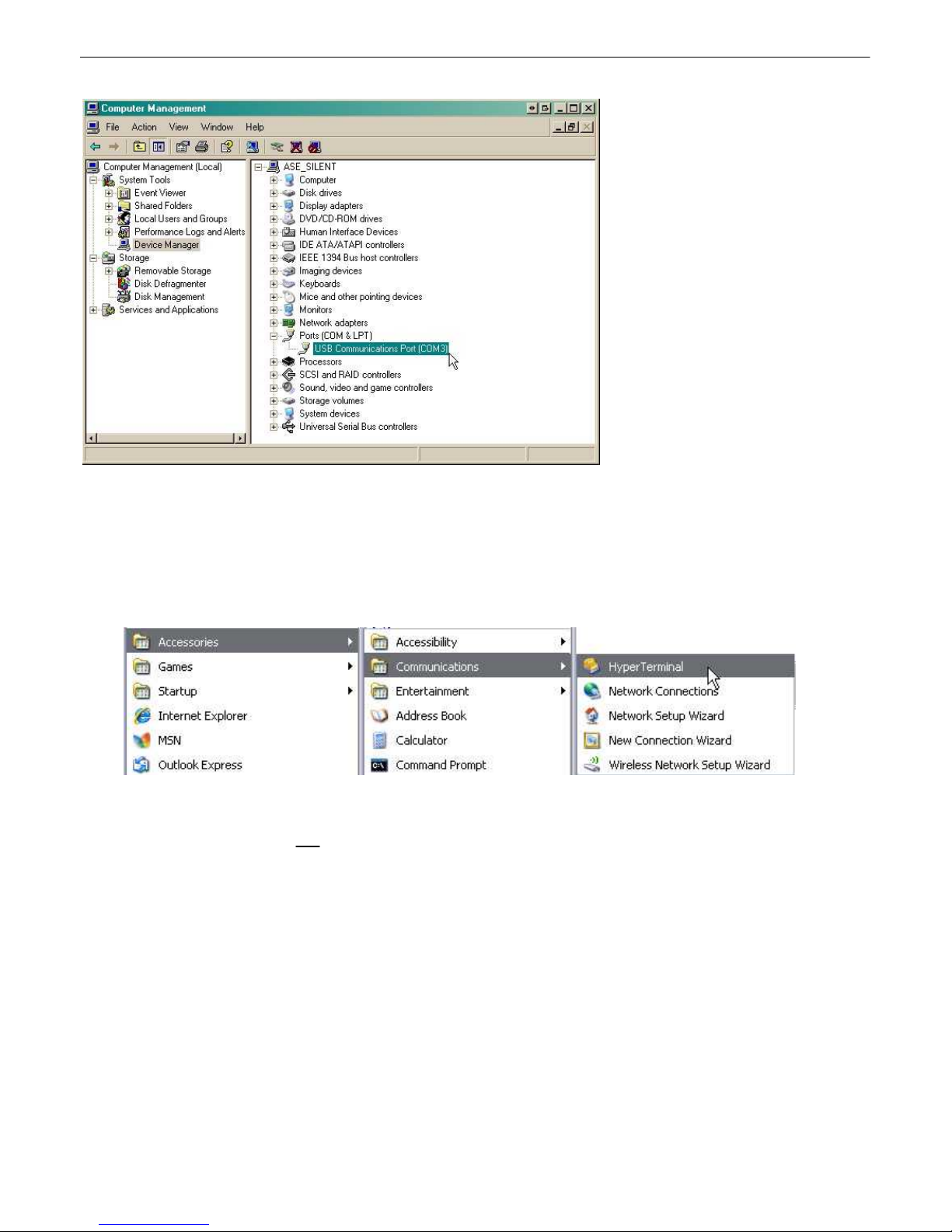
9. Right-cli ck t he "My Computer" icon on your de skt op, then click " Ma nage"
10.Cl ick "De vice Manag er" in th e left pane.
Page 22
18
11.Expand t he "Ports (COM & LPT)" section in the ri ght pan e. Look f or "USB Communications Port
(COM x)". N ote the number of th e COM port (" COM3" i n the example ab ove).
Now that you kno w which COM port to use, it 's time to launch HyperT erminal (or oth er terminal
software):
12.Cl ick on the Start menu > select Programs > Accessories > Communications >
HyperTerminal.
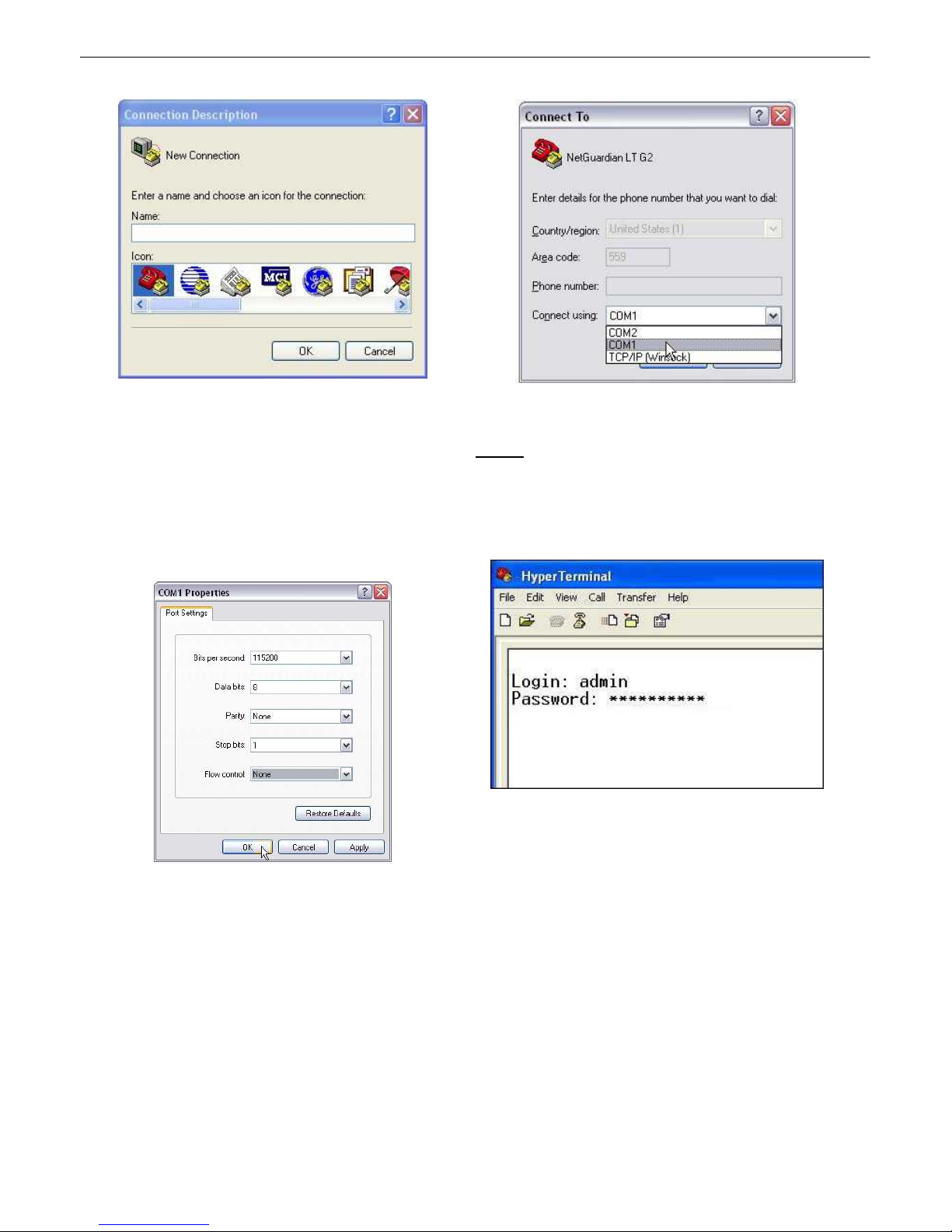
13. At the Connectio n Description screen , enter a
name fo r t his conn ection. Yo u may also select an
icon. The name and icon do not aff ect yo ur ability
to conn ect to t he unit .
14. At the Connect To screen, use th e drop-
down men u to select the COM port you found
earl ier in th e Device Manager.
Page 23
19
15. Select the followin g COM port o ptions:
• Bits pe r second: 1152 00
• Data bits: 8
• Pari t y: None
• Stop bits: 1
• Flow contro l: None
Once connected, you will see a bl ank, whi t e
HyperTermin al screen. Press Enter to activ ate
the conf igurat ion menu.
16. When prompted, e nter the defaul t user
name admin and password dpstelecom.
NOTE: If you don't receive a prompt f or your
user name a nd password, check the Com port
you are using on you r PC a nd make sure you
are u sin g the cable provi ded. Additional cab l es
can be ordered f rom DPS Telecom.
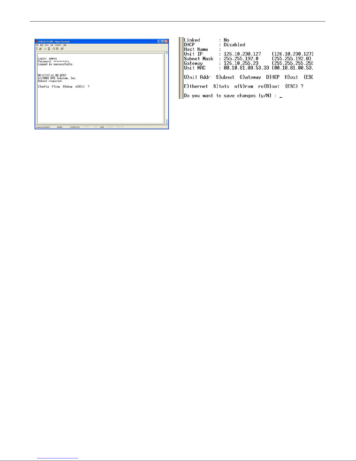
17. T he Cell2 Interface's main men u will appear.
Typ e C for C)onfig, then E f or E)therne t . Co nfigure
the unit's IP address, subnet mask, a nd defa ult
gateway.
18. ESC to the main men u. When asked if
you'd like to save your chang es, type Y f or Y)es.
Reboot the Cel l2 I nterface to save its new
configuration.
Page 24
20
Now you' re re ady to do the rest of your configuratio n via L AN . Plug the Ce ll2 Interface i nto your LAN
and see t he "Logging On t o the Cell2 I nterface" section to contin ue data basing using t he Web Browser.
Page 25

...via LAN7.2
To connect to the Cel l 2 I nte rfa ce via LAN, a l l you nee d i s the unit's I P addre ss (Defaul t IP addre ss is
192.168.1.100).
If you DON'T have LAN, but DO have ph ysical access to the Cell2 Inte rface, connect us ing a LAN crossover
cable. NOTE: Newer PCs should be able t o use a st andard straight-through LAN cable and handle the crossover for
you. To do this, you will temporarily change your PC's IP addres s and subnet mask to mat c h the Cell2 Int erface's
factory default IP set t ings. Follow these s t eps:
1. Get a LAN crossover cable and plug it direct l y into the Cell2 Interface's LAN port.
2. Look up your P C's current IP address and subnet mask , and write this informat ion down.
3. Reset your PC's IP addr e ss to 192.168.1.200. Cont ac t y our IT depart ment if you are uns ure how to do t his .
4. Reset your PC's subne t mask to 255.255.0.0. You may have to reboot your PC to apply y our changes.
5. Once the IP address and subnet mask of your computer coincide with the unit , y ou can acc es s t he Cell2
Interface via a Telnet session or via Web browser by using the unit's default IP address of 192.168.1.100.
6. Provision the Cell2 Interface with the appropriate information, then change your compute r's IP a ddress
and subnet mask back to their orig i nal settings.
Now you're ready to do the rest of your c onfigurati on via LAN. Plug your LAN cable into the Cell 2 Interface and see
Sect ion 9, "Logging On to the Cell2 Interface" t o continue databasing using the Web Browser.
21
Page 26

22
8
WARNING: Do no t reset o r power off the modem durin g activation.
1. Set up you r wi reless da t a account t hrough Mu lti-Tech or y our prefe rred service pro vider.
2. Verify that th e anten na is screwed onto the back panel of the unit.
3. Locate the Model # and ESN/MEID. These can be found on the Read Me First pag e that is in clu ded
with your unit, or on t he back panel of your de vice.
4. G o to th e Mul ti -Te ch Sup p o rt p a g e a n d op e n the l in k for 'Cellul a r Mode m A ctiv a t i o n'
5. Fo llow the instructions that are associat ed with your modem model a nd service pro vider.
Important: I f you are havin g troubl e findi ng you r mod em's mode l number, please contact DPS suppo rt
at 559-454-1600.
Wireless Mod em Activati o n
www.multitech.com
Page 27
23
9
TTY Interface
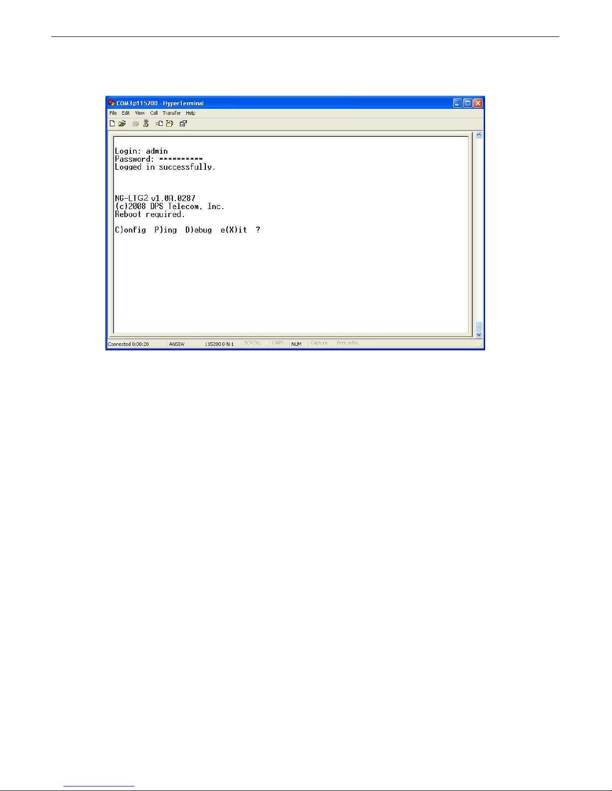
Fig. 6.1 The TTY interface initial configuration screen
The TTY interface is the Cell2 Interface's built-in interface for basi c c onfigurat ion. Y ou can configure unit's Et hernet
port settings, view debug, and m onitor alarms. For more advanced c onfiguration tools, please use t he Web Browser
Interface.
Some initial s oftware c onfigurati on must be performed before you can use a remote c onnection to t he Cell2 Interface.
For Telnet, c onnect t o the IP addres s at port 2002 to access t he configurat ion menus after initial LAN/WAN s etup.
The same TTY interface i s available through the front craft port. Te l net sessions are esta bl i shed at port 2002, no t
the standa rd Tel net port as an added security measure.
NOTE: The default TTY username is "admin" and the password is "dpst elecom" .
Me nu S hortcut Keys
The lett ers before or enclosed in parentheses () are menu s hortcut k ey s . P ress t he shortcut k ey t o acc es s t hat
option. Pressing the ES C key will always bring you back t o the previous level. Entries are not case s ensit ive.
Page 28
24
10
The Cell2 Int erface features a built-in Web Browser Interface that allows you to manage alarms and configure the unit
through t he Internet or your Intranet. Y ou can quickl y s et up alarm poi nt desc ripti ons, vi ew alarm status, issue
controls, configure paging information, and m ore using most c ommonly used browsers.
The web interface can be acces s ed using a secure, SS L-encrypted connection. To ac cess t he web interface using
secure brows ing, jus t prefac e t he IP address with "htt ps : / / " ins t ead of " ht t p:/ / " .
For Web Int erface funct ionality , t he unit must first be configured with some basic network inform ation. If this st ep
has not been done, refer to the sec t ion "Quic k S t art: How to Connect t o the Cell2 Int erface" for inst ruct ions on initial
configuration set up.
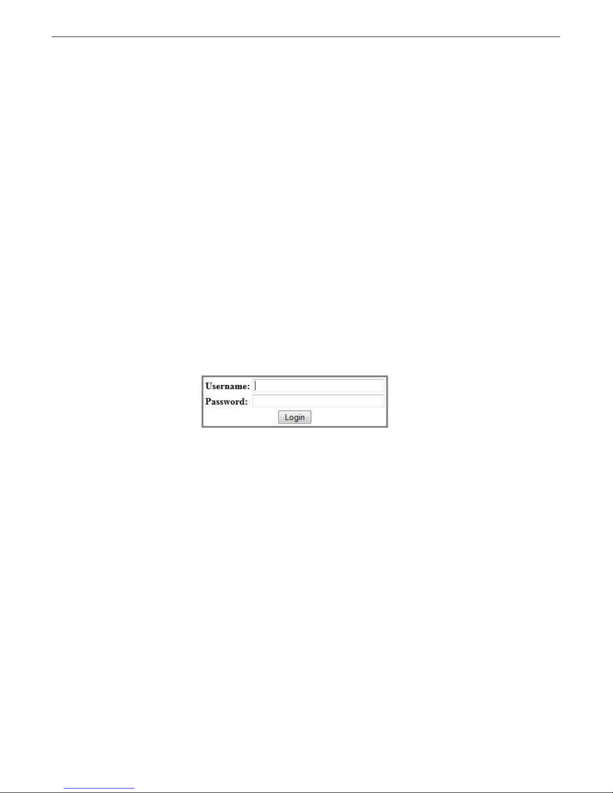
1. To c onnect t o the Cell2 Int erface from your Web brows er, enter its IP address in t he addres s bar of your web
2. After connecting to the unit's IP address , enter your login information and c l ic k OK .
3. In the left fra me you will see the Monitor menu (blue) and Edit/Provisioning menu (green) The Monitor menu
Log g i n g o n to th e Cell2 Interface
NOTE: Only one user access t he Cell2 Int erface via the Web at a time.
brows er. It may be helpful t o bookmark the logon page to avoid entering this each time.
NOTE: The factory default us ername is "admin" and the password is "dpstelecom".
links are used to view the current s t at us of alarms. The E dit menu is us ed to change the uni t 's c onfiguration
settings. All the software configu ration will occur in the Edit menu. The following sec t ions provide detailed
information regarding these functions.
Enter your pass word to enter the Cell2 I nterface Web B rows er Interface
Page 29
25
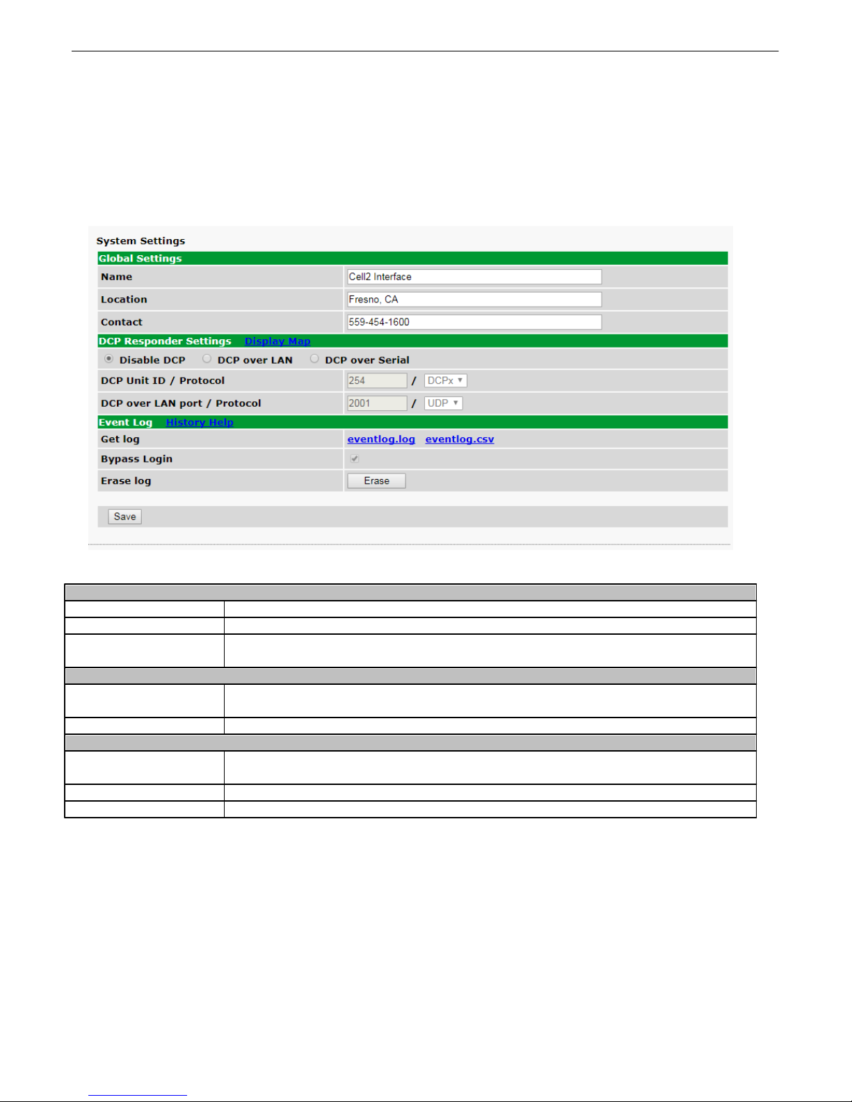
Globa l S ystem S ettings
Name
A name for this Cell2 Interface. (Optional field)
Location
The locati on of this Cell2 Interface. (Optional field)
Contact
Contact telephone number for the person res ponsible for this Cell2 Interface. (Optional
field)
DCP Res ponder Settings (For use wi th T/ Mon)
DCP Unit ID / Protocol
User-definable ID number for the Cell2 Interface. This ID is used by T/Mon to
assoc iat e syst em alarms t o the Cell2 Int erface.
DCP over LAN port
Enter the DCP port for this Cell2 Interface (UDP/TCP port ).
Event Log
Get Log
Download a log of all alarm events in either plain t ex t (event.log, open with Not epad) or
spreadsheet format (eventlog.csv, open with Exc el).
Bypass Login
File can be downloaded wit hout logging in when check ed.
Erase Log
Click t his butt on to c lear the log.
11
Provisioning
System11.1
From the Provisioning > System menu, y ou will configure and edit the Global S ett i ngs and DCP Res ponder
Settings.
The System Provisioning Window
Page 30
26
User Profiles11.2
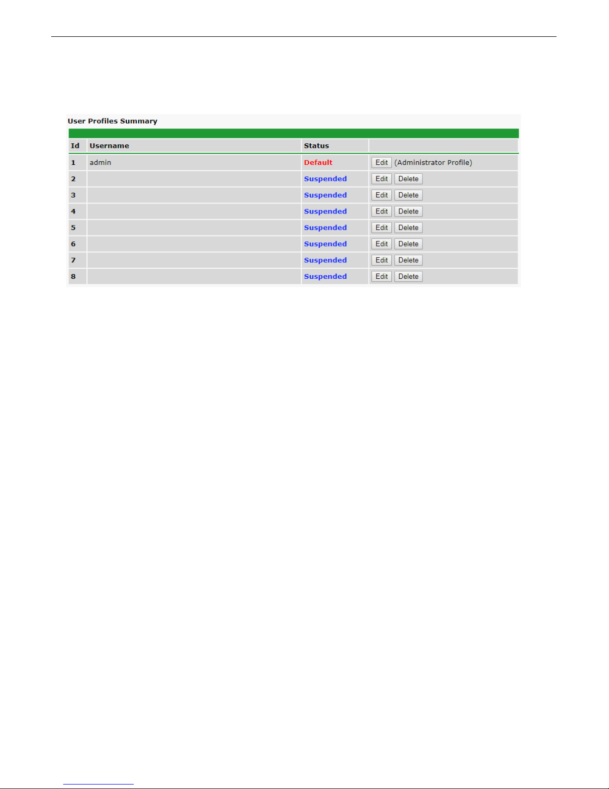
User profiles can be manage d from the Provisioning > Use r Profil es screen.
User Profile Configuration
Use the foll owing steps to c onfigure user profiles :
1. From the Provisioning menu select Use r P rofil es.
2. Click Edit to edit any of user profiles.
3. Enter the new user name in the User field (or t ype the same name used previously ).
4. Enter the new password in the Password field.
5. Check off t he Ac c es s Right for the new user.
6. Click the Save button.
7. Click the Write button in the Device Access menu on t he left.
NOTE: The pass word of the admin user profile must m atc h t he password of ALL configured Cell2 devices being
polled by this Cell2 Interface device.
Page 31
Ethernet11.3
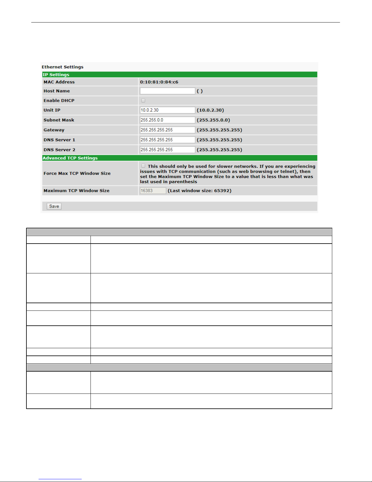
Etherne t Settings
MAC Address
Hardware address of the Cell2 Interface. (Not editable - For referenc e only. )
Host Name
Used only for web browsing. E x ample: If you don't want to remember t his Device's IP
address, you can type in a name is this field, such as SMSBX. Once y ou save and reboot
the unit, you c an now browse to it loc ally by s i mply t y ping in "SM S B X" in the address bar.
(no "http:// " needed).
Enable DHCP
Used to turn on Dynamic Host Connection Protocol. NOT recomm ended, because the
unit is as s igned an IP address from your DHCP server. The IP you've already as s i gned to
the unit becomes inacti ve. Us ing DHCP m eans the unit will NOT operate in a T/Mon
environment.
Unit IP
IP address of the Cell2 Interface.
Subne t Mask
A road sign to the Cell2 Interfac e, t elli ng it whether your packets should stay on your
local network or be forwarded somewhere else on a wide-area network.
Gateway
An important paramet er if you are c onnected to a wide-area network. It t ells t he Cell2
Interface which machine is the gateway out of y our local network. Set t o 255.255.255.255
if not us ing. Contact your net work administ rator for this info.
DNS Serve r 1
Primary IP addres s of the domain name server. Set t o 255.255.255.255 if not using.
DNS Serve r 2
Secondary IP address of the domain name server. Set t o 255.255.255.255 is not using.
Advanced T CP Settings
Force Max TCP
Wi ndo w Si z e
This s hould only be used for slower networks. If you are experiencing issues with TCP
communicat ion (such as web browsi ng or telnet), then set the Maximum TCP Window
Siz e to a value that is l ess than what was las t us ed in parenthes is .
Ma xim um TCP
Wi ndo w Si z e
Amount, in byt es , of the maximum allowed TCP window.
The Provisioning > Ethernet menu allows you to define and configure Ethernet settings .
27
The Ethernet S ett i ngs Window
NOTE: DNS Server setting are required if a hostname is being used for ping target s.
Page 32
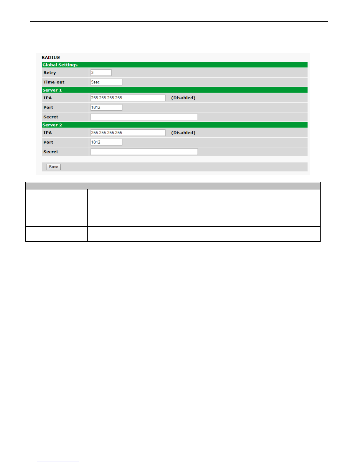
28
Radius Settings
Retry
In the event the RAD IU S Server is not reachable, number of time s to reattempt
connection.
Time-out
Configures N umbe r of Seconds the devic e w a its for a response from a RADIUS Server
before retrying the authentication reque s t.
IPA
IP Address of RADIUS Server.
Port
UDP Port used for RADIUS authentication messages (default: 1812).
Secret
Shared secret that is used to secure communications with the RADIUS Server.
RADIUS11.4
Page 33
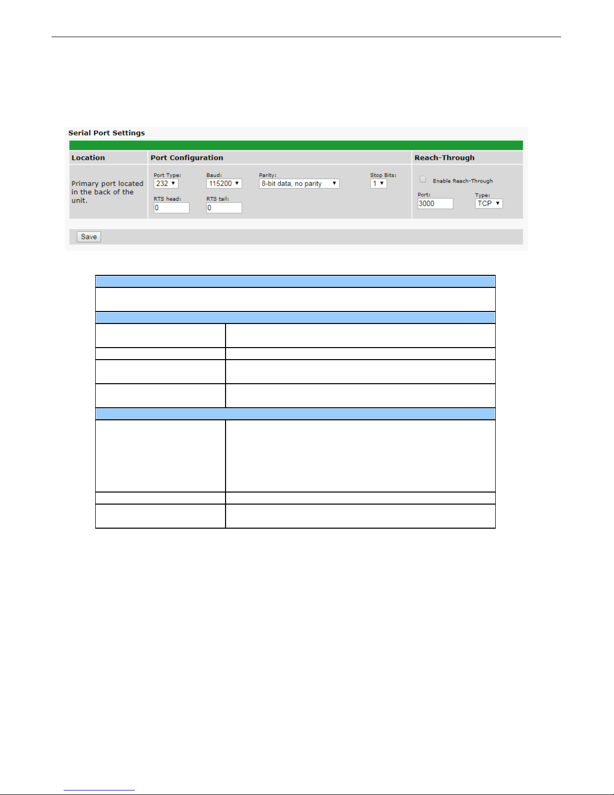
Serial Port11.5
Location
A reminder t hat y our primary serial port is l ocat ed on the back of the Cell2 Interface
chassis.
Port Configuration
Port Type
Select t he s erial port for your build of the Cell2 Interface.
Choos e from 232, 485...
Baud, P arity, and Stop Bits
Select t he appropriate set t ings from the drop-down m enu.
RTS Hea d
Only used if your Cell2 Interface was built with a 202
modem. The most commonly used value is 30.
RTS Tai l
Only used if your Cell2 Interface was built with a 202
modem. The most commonly used value is 10.
Rea ch-Through
Enable Reach-through
Checking this box enables the port to be used as a terminal
server. Most commonly used to Telnet t hrough the port over
LAN to a hub, s wit c h, or router. From a command prompt ,
type the following (note the spaces between each entry):
telnet [IP addres s] [ port]
Example: t elnet 192.168.1.100 3000
Port
Port number us ed for reach-through t o a serial device.
Type
Select TCP or UDP t raffic t o be passed through t o a serial
device.
The P rovisioning > S erial P ort menu allows you to change setti ngs depending on the port type of your Cell2
Interface. From this menu, y ou can select a mode of operation and enable reac h-through seri al port func t ionality.
The Provis i oning > Serial Ports menu
29
Page 34
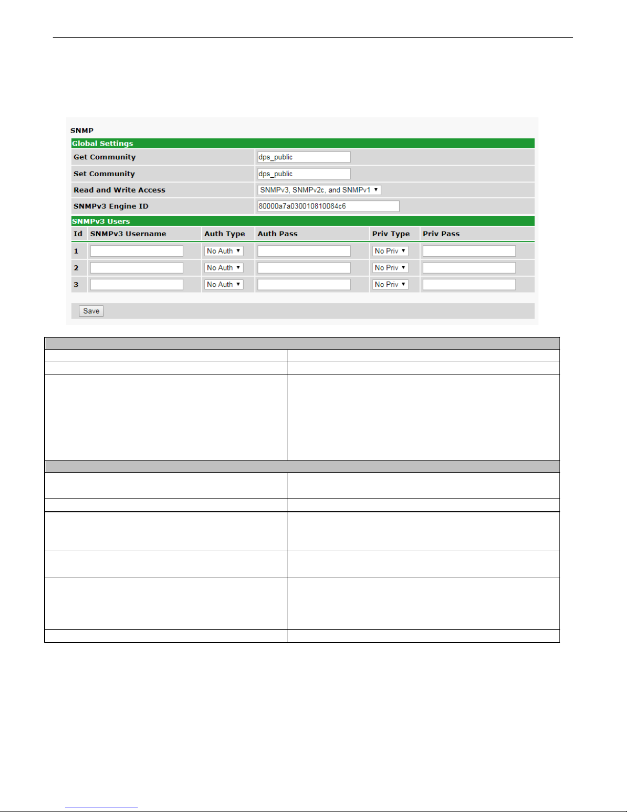
30
SNMP Global S ettings
Get Commu ni ty
Community name for SNMP GE T request s .
Se t Comm uni ty
Community name for SNMP S E T request s
Rea d and Write Access
This field defines how the Cell2 Interfac e unit may be
acces s ed via SNMP. This can be set t o the following:
· Access Disabled - Restrict s all acc es s t o unit via
SNMP.
· SNMP v2c only - All ows SNMP v2c access only .
· SNMP v2c and SNMP v1- Allows only SNMP v1 and
SNMP v2c access .
SNMPv3 Users
ID
Inde x number corresponding to the SNMPv3 user defined
in this row.
SNMPv3 Usernam e
Username to ma tch for authe ntic a tion.
Auth Type
Provides authentication on user name match only
(NoAuth), Hashed Message Authentication Code
(HMAC) - MD5, or HMAC-SHA1 alg o rithms.
Auth Pass
Pa s sw ord to match for authentic ation if using MD5 or
SHA1.
Priv Type
Priv acy Type to use in con junctio n with authenticati on.
No Priv- No Priva cy algorithm will be used.
AES - Use Advanced Encrypti o n Stand ard .
DES- Use Data Encryption Standard.
Priv Pass
Pa s sw ord to match for the c hosen Priv Type.
SNMP11.6
SNMP Global Settings can be managed from the Provisioning > SNMP window.
Page 35
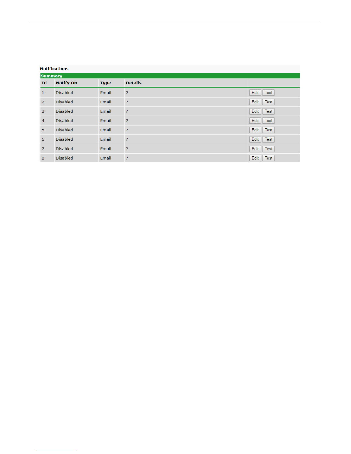
Notifications11.7
By clicking on the Notifications bu tton in the Provisioning menu, you c an configure and manage the notifications
your Cel l2 Interface s ends.
31
Page 36
32
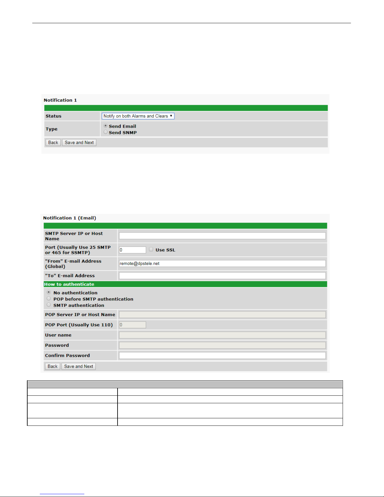
Edit Em ail Notifica tions
SMTP S erve r I P o r Host Nam e
The IP addres s of your email server.
Port (Usual l y Use 25)
The port used by your email server to rec eive emails (usually port 25).
"From" E-mail Addre ss
(Global)
Displays t he email address (defined in the Edit menu > Sy s t em) that t he Cell2
Interface will send email from. Not editable from t his menu.
"To" E-m ail Addre ss
The email addres s of the person who wi ll receive email alarm notifications.
11.7.1 Email N oti f i cations
1. Click on the Notifications b utton in the Provisioning menu and click on the Edit button.
2. You will then be prompted to select t he notification ty pe you would like to configure (Send Email or Send
SNMP). Select S end Ema i l then click S ave and Ne xt.
3. Enter a valid email address in the "From " Ema i l Addre ss field. (You may need to check with y our IT depart ment
to have one c reated for t he unit). This is t he address that will appear in y our email as the sender. Enter your
additional SMTP information and the Email ac c ount where t he email notifications will be sent. If aut henticat ion is
required, choose the type and fill in the necessary fields. When your sett ings have been configured, c l ick S ave and
Next.
Page 37
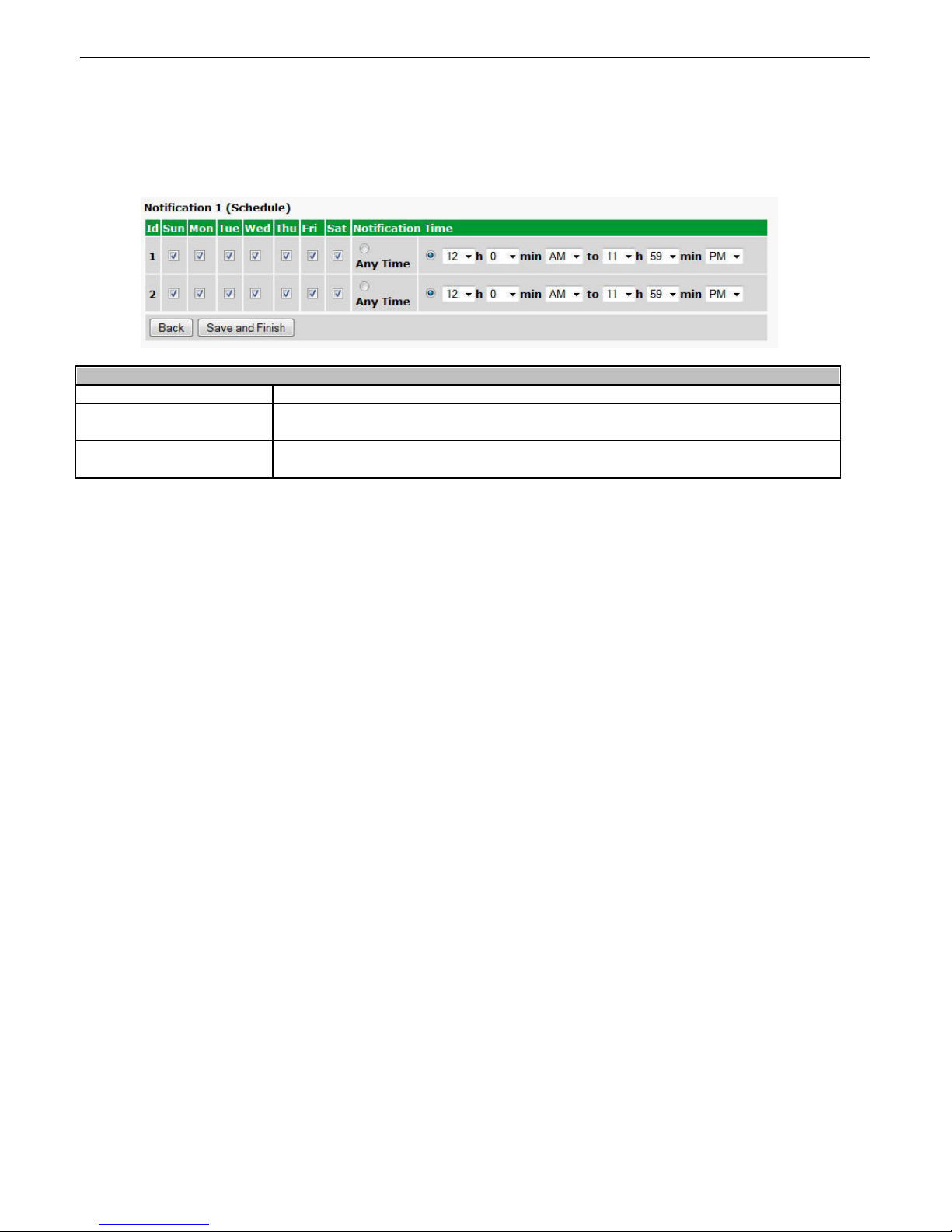
4. Next, you can define the Notification Schedule. Select t he days of the week and t he time period for when y ou
Notification Scheduli ng
Days of the wee k
Check which days y ou want to receive notifi c ati ons.
Any Time
Select t o t ell t he Cell2 Interface you want t o receive alarm notifications at any
time for the day (s) y ou've selected.
Notification Ti m e
Used to tell the Cell2 Interface to only send alarm notificati ons during certain
hours on the day(s) you've selected.
would li k e to receive Em ail notifications . If you want t o receive Email notificat ions at all t i mes on the days y ou've
selected, then just select the Any Time radio button. When you have configured your Notificat ion Sc hedule, clic k
Sa ve and Fi ni sh.
33
Page 38
34
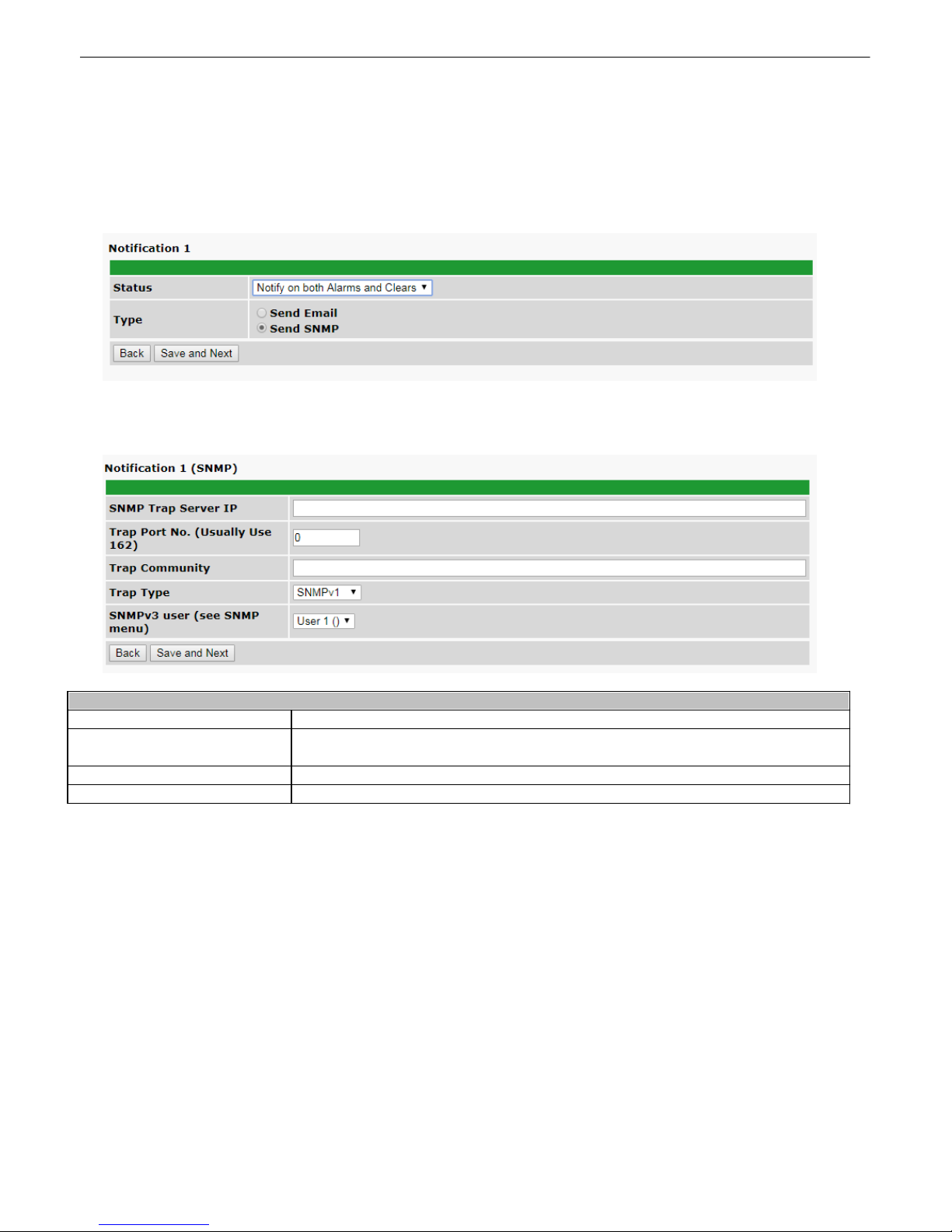
Edit SNMP Traps
SNMP Tra p S erve r I P
The SNMP t rap manager's IP addres s .
Trap P ort No. (Usua l l y Use
162)
The SNMP port (UDP port ) set by t he SNMP t rap manager to receive traps,
usually s et t o 162.
Trap Com m uni ty
Community name for SNMP TRAP reques t s .
Trap Type
Indic at e whether you would like to s end SNMPv1 or v2c traps.
11.7.2 SNMP Traps
1. Click on the Notifications b utton in the Provisioning menu and click on the Edit button.
2. You will then be prompted to select t he notification ty pe you would like to configure (Send Email or Send
SNMP). Select S end S NMP then click Save and Next.
3. Enter the IP address of your SNMP Manager, t he Trap Port No. (whi c h is us ually 162), the Trap Community, and
the Trap Type. When y our settings have been configured, click Save and Next.
Page 39
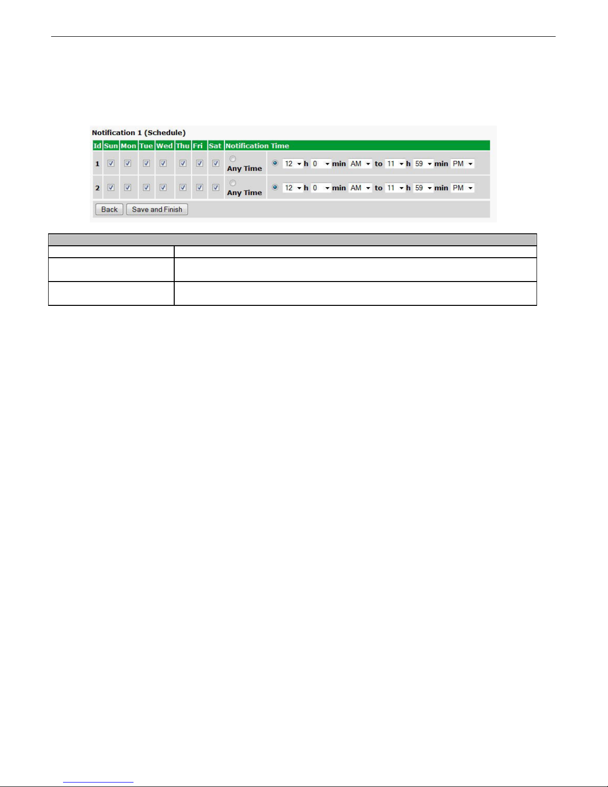
4. Next, you can define the Notification Schedule. Select t he days of the week and t he time period for when y ou
Notification Scheduli ng
Days of the wee k
Check which days y ou want to receive notifi c ati ons.
Any Time
Select t o t ell t he Cell2 Interface you want t o receive alarm notifications at any
time for the day (s) y ou've selected.
Notification Ti m e
Used to tell the Cell2 Interface to only send alarm notificati ons during certain
hours on the day(s) you've selected.
would li k e the Cell2 Int erface to send SNMP Traps. If you want t o receive SNMP Traps at all t i mes on the days
you've selected, then just select the Any Time radio but t on. When you have configured your Notification Sc hedule,
click Sa ve and Fi ni sh.
35
Page 40
36
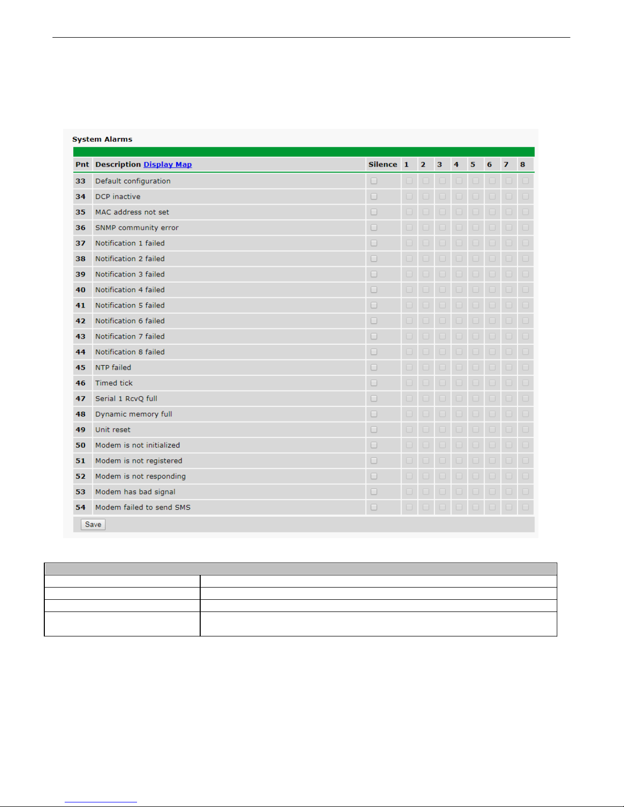
Editing Syste m Alarms
Pnt (Point)
Alarm point number.
Description
Non-editable description of the connec t ed unit.
Silence
Check to si lence this alarm.
Notification Devi ce s
Check which notification device(s), 1 through 8, y ou want to send alarm
notifications for that alarm point.
System Alarms11.8
You can c onfigure the sett i ngs for the connected Decvice's system alarms by going to the Syst em Alarms window
in the Provisioning menu.
The System Alarms Window
Page 41
37
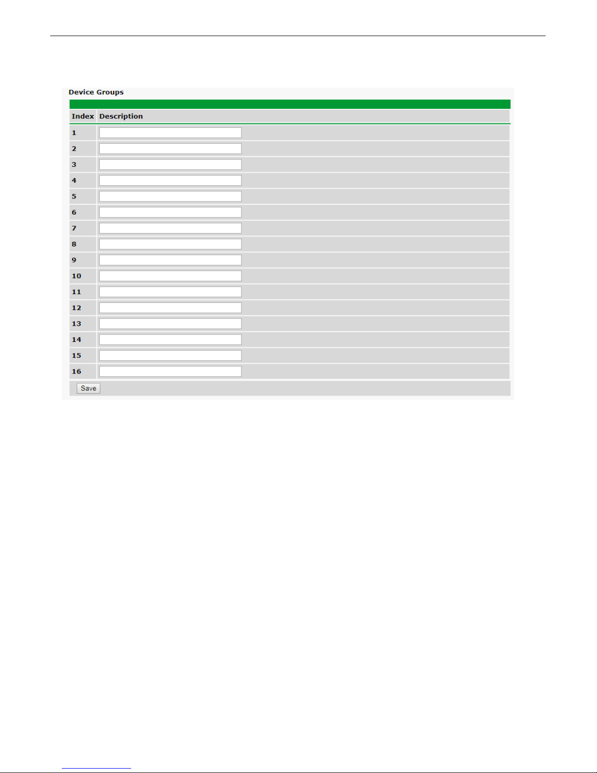
Device Groups11.9
The Cell2 Interfac e can configure up to 16 different groups of devices. You can enter your own desc ription for
eac h group here.
Page 42
38
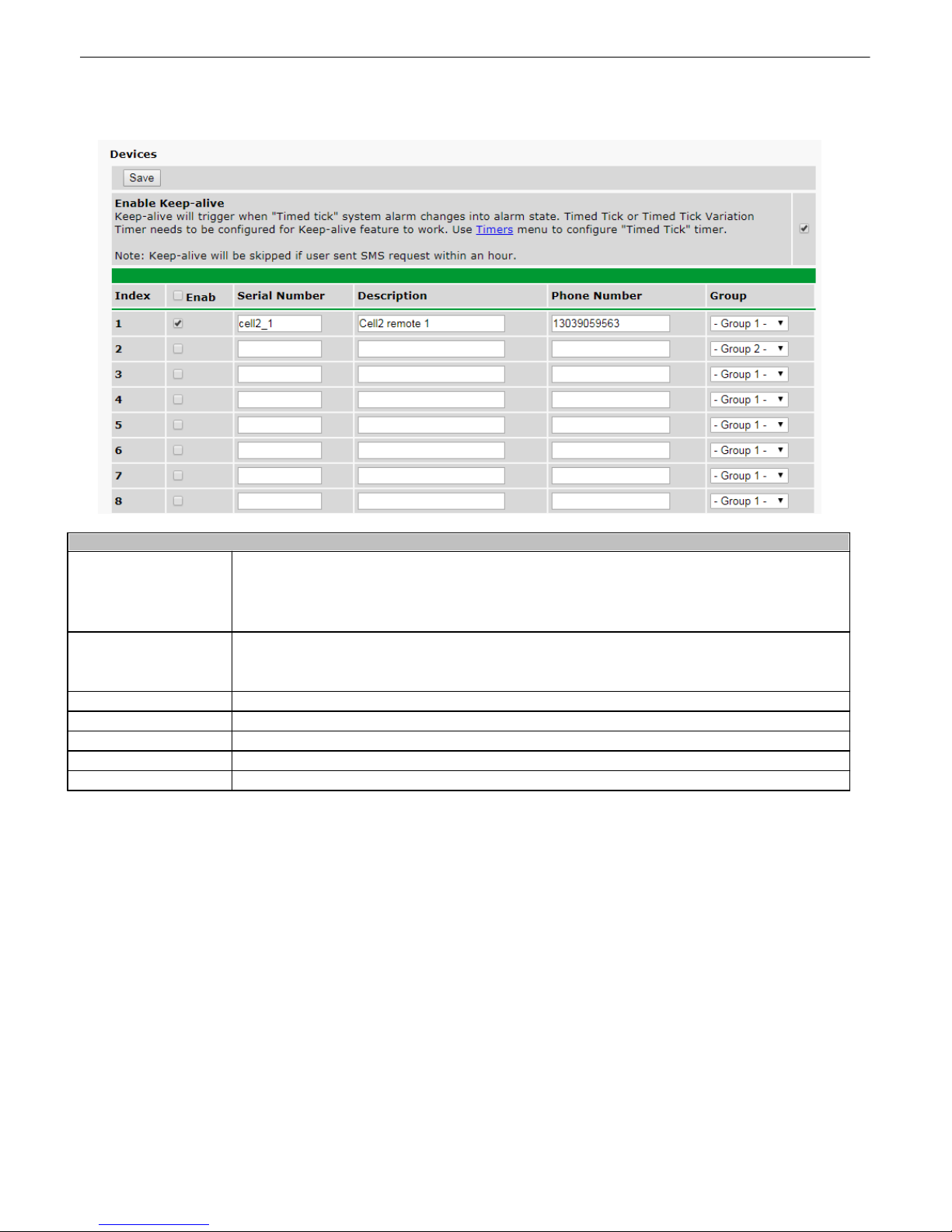
Device S ettings
Enable Keep-al i ve
Checking the box here w ill e nable a kee p-alive functionality associated with the "Timed
Tick" changing into an alarm state. Timed tic ks ca n be configure d in the timers menu.
NOTE: Ke e p-alive func tionality will be s kipped if a user se nd a SMS re quest within an
hour.
Index
Devic e number c onfigured in this row. A Ce ll2 Remote devic e can be configured to be
polled by T/Mon through the Cell2 Interfac e devic e by s e tting the Unit ID to the device's
corresponding index.
Enab
Check the box to enable SMS reque s ts a nd T/Mon polling to the configure d device .
Se ri al Number
Serial number of the Cell2 Remote.
Description
User-defina ble description of the Cell2 Remote.
Phone Num ber
Contact phone number associated with the Ce ll2 Remote.
Group
Devic e Group this device belongs to.
Devices11.10
Page 43
39
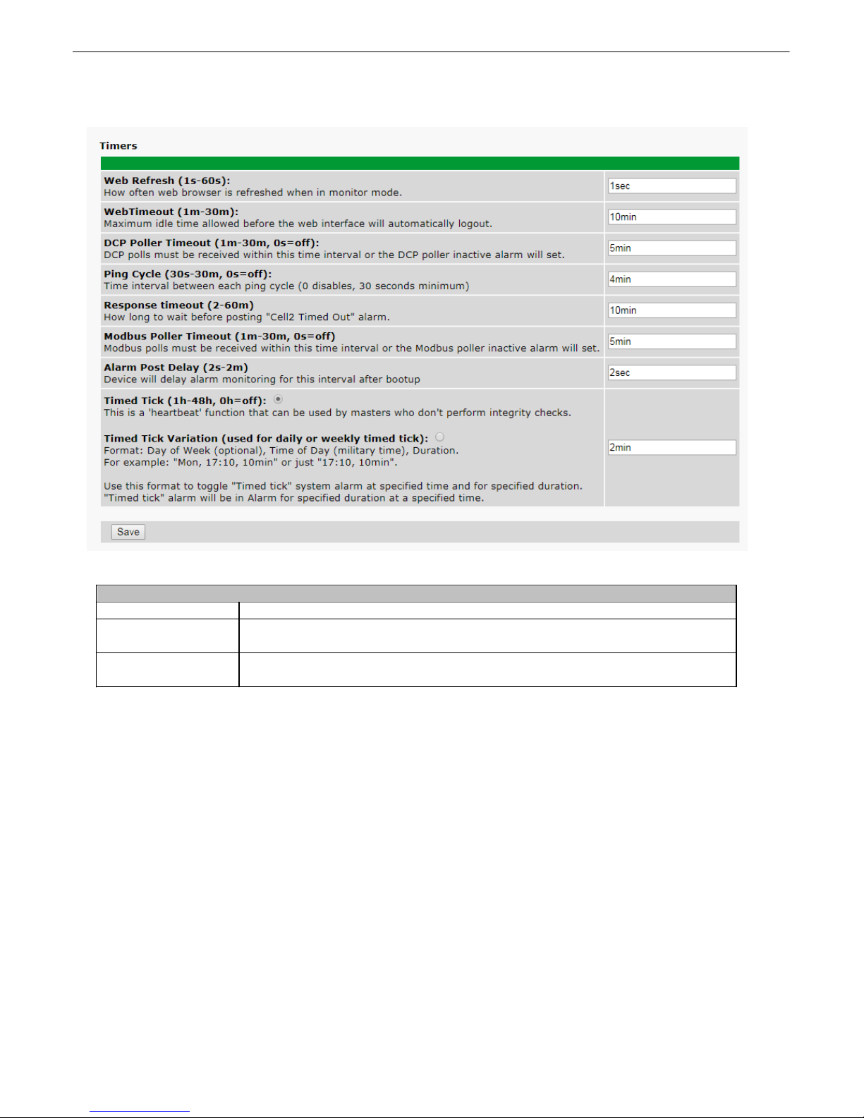
Editing Timers
Web Refre sh
How often web browser is refreshed when in monitor mode.
Timed Ti ck
This is a "heartbeat" func t ion that c an be used by masters who don't perform
integrity c heck s .
DCP Poller Tim eout
DCP pol ls m ust be received within this ti me interval or the DCP poller inactive
alarm will set.
Timers11.11
The Timers Window
Page 44
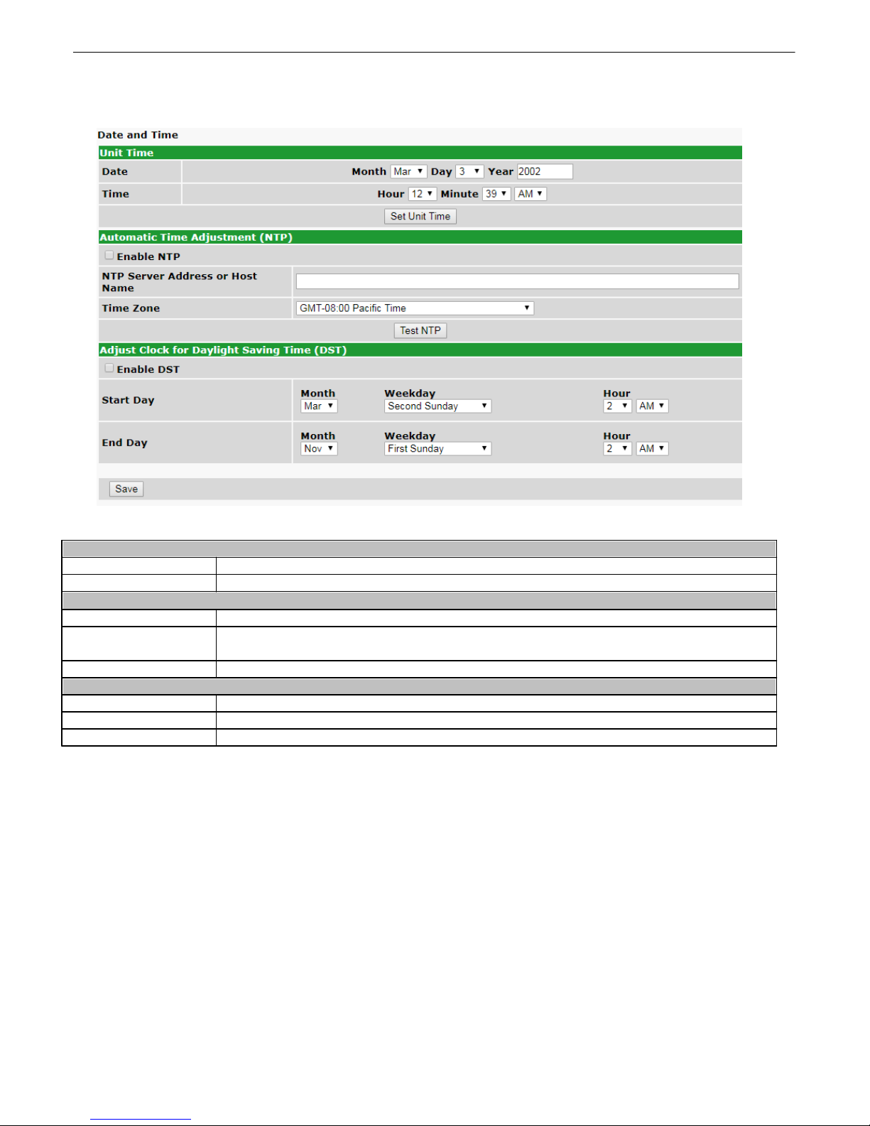
40
Time Settings
Date
Select t he c urrent month, day, and year from the drop-down menus .
Time
Select t he c urrent hour, mi nutes, and time of day fro the drop-down menus .
Automatic Time Adjustment (NTP)
Enable NTP
Check this box t o enable Network Time Protocol.
NTP Se rve r Addre ss or
Host Name
Enter the NTP server's IP address or host name, then click Sy nc.
Example: ht t p:/ / us . pool.ntp.org/
Time Zone
Select your time zone from the drop-down menu.
Adjust Clock for Daylight Savings Time (DST)
Enable DST
Check t his box to have the Cell2 Interface observe Daylight Savings.
Start Day
Select t he month, weekday, and time when Day li ght Savings will begin.
End Day
Select t he month, weekday, and time when Day li ght Savings will end.
Date an d T ime11.12
The Dat e and Time Window
Page 45
41
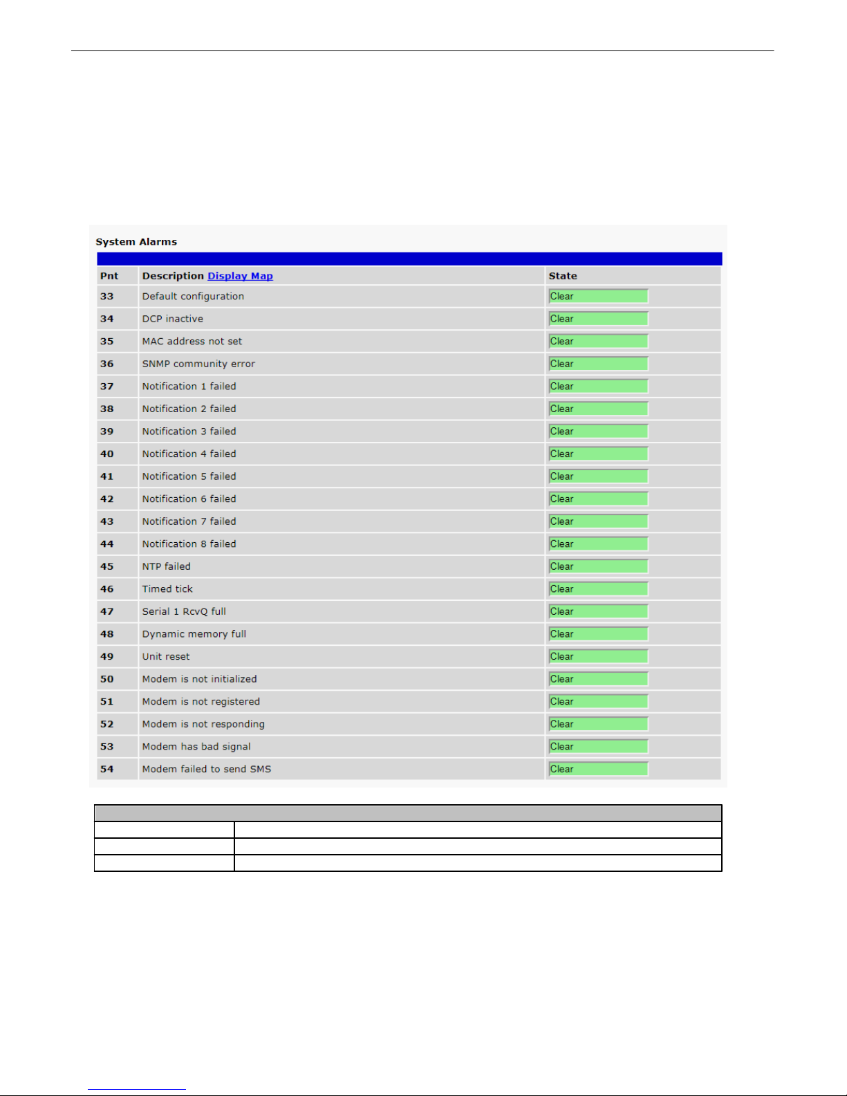
Syste m Alarms
Pnt (Point)
Alarm point number.
Description
Non-editable description of the connec t ed unit.
State
Ind icates whether the alarm is in a Clear or Alarm state.
12
Monitor
System Alarms12.1
T o v iew Sys tem Alarms, click on Syst em Alarms under Monitor. This window will s how the connection state of
each Cell2 as sociated to the Cell2 Int erface.
Page 46
42
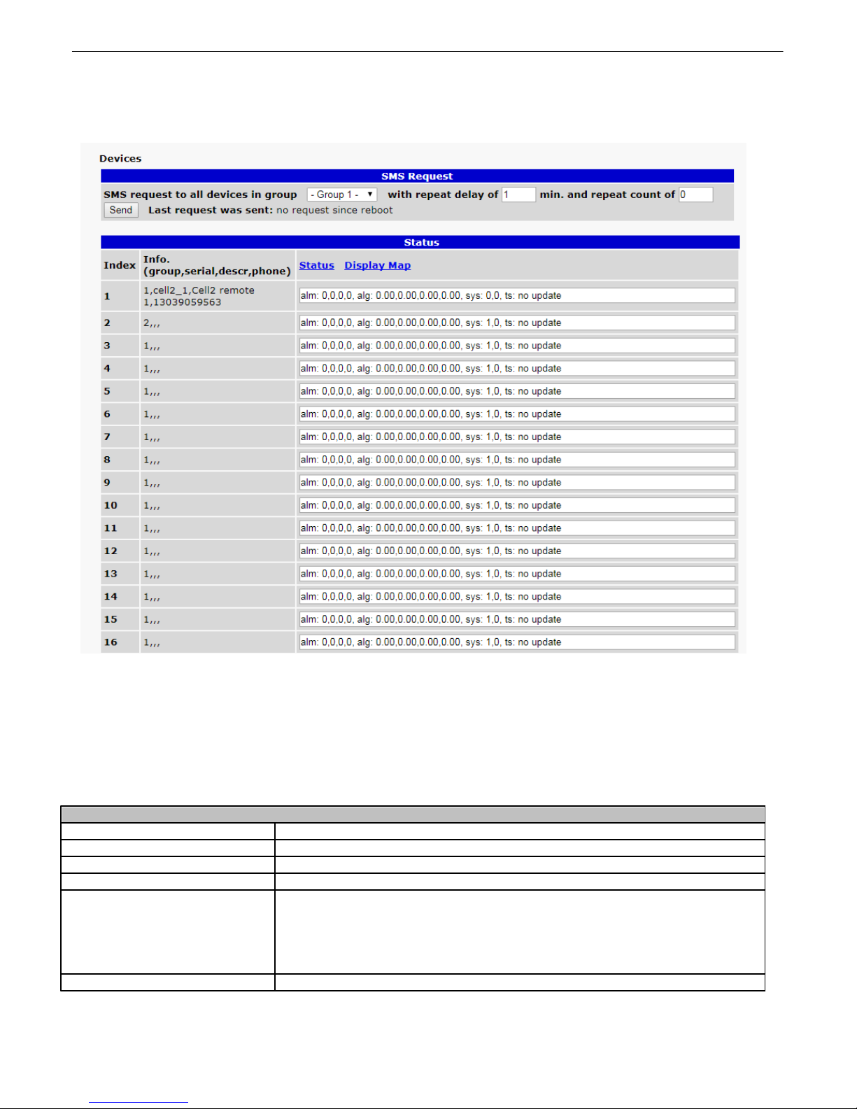
Status
Index
Device index number
Info
All info associat ed with the device.
alm
Status of discrete alarms 1, 2, 3, 4
alg
Status of analog alarms 1, 2, 3, 4
sys
2 numbers - The first number will be 0 if configured and enabled in provi s ioning.
Wil l be a 1 if not c onfigured or disabled, and alarm 63 will be trapped by a
configu red T/Mon.
Second number will be 0 if a t i meout has not occ ured, and 1 if ti meout has
occured.
ts
Tim es t amp of the most recent device update.
Devices12.2
The Devices page shows the stat us of all confi gured Cell2 Remote Units.
SMS Re qu est
Wit h t he SMS request, a SM S will be sent t o a configured group wit h an initial delay of 0 m inutes (respond
immediately after received) , a repeat delay of user defined minutes (repeat delay c onfigured in monitoring>devices)
for each of the remaining mess ages (repeat c ount c onfigured in monitoring>devices).
If 255 is entered in the repeat count, t he Cell2 remot e's request will indefinit ely mes s age at the determined repeat
delay interval until a new SM S or heart beat overrides the indefinite comm and.
Page 47
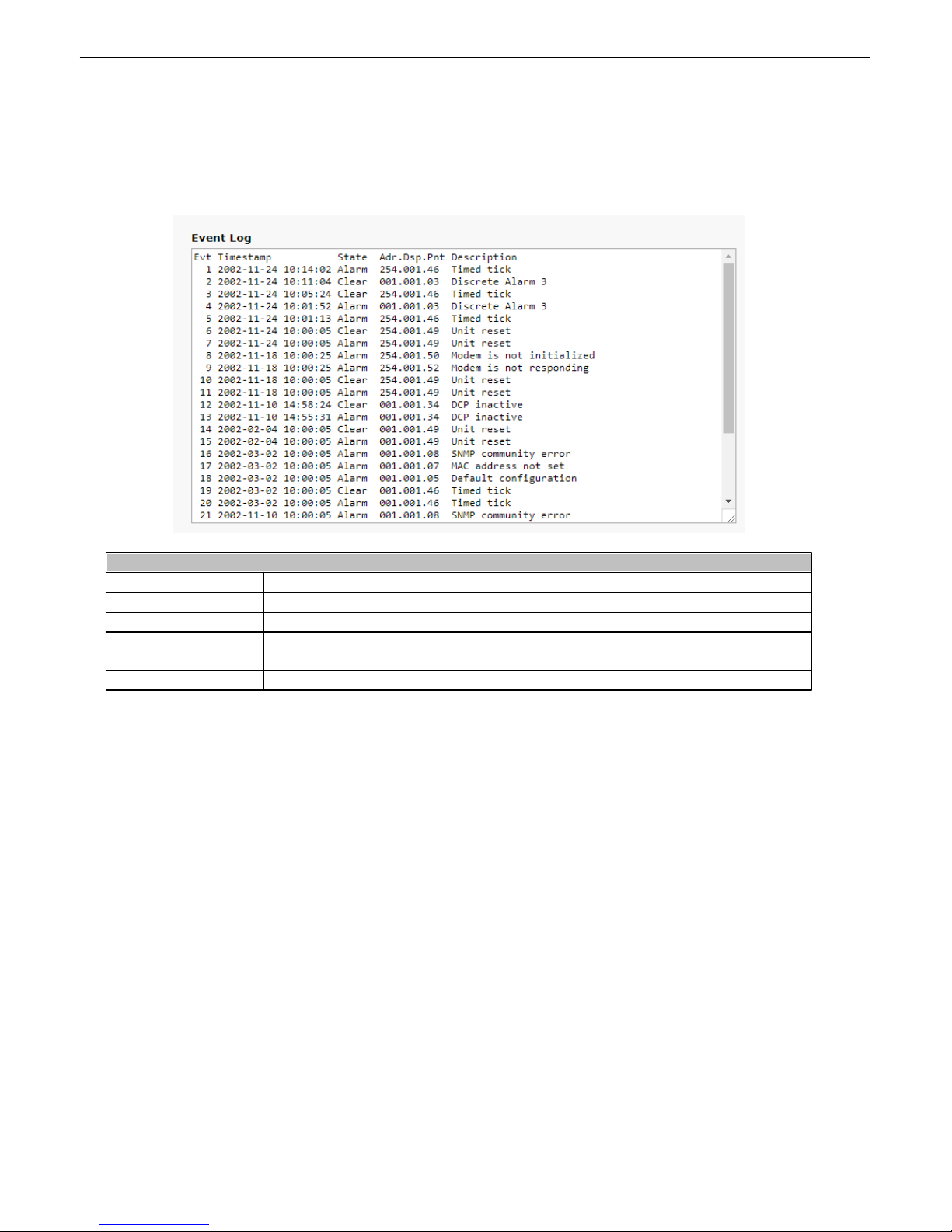
Event Log12.3
Wi reless Eve n t Log
Evt
Numeric value for event.
Timestamp
Date and time whe n the event occurred .
State
Alarm st ate
Adr.Dsp.Pnt
Adr values 1-253 correspond to configured Cell2 units , while an Adr value of 254
corresponds t o an alarm on the Cell2 Interface unit.
Description
User-d efined description of the device
The Event Log options (Under the Monitor menu select Event Log) displays an event log containing alarm events .
You can select the refresh rate using the Refre sh Rate drop down box. You c an also clear the event log by
clicking the Erase button.
43
NOTE: Rebooting the Cell2 Int erface clears the event log, which is s t ored in volatile memory.
NOTE: These events are also saved to the non-volatile hist ory log found under D evice Access > Ge t History.
Page 48
44
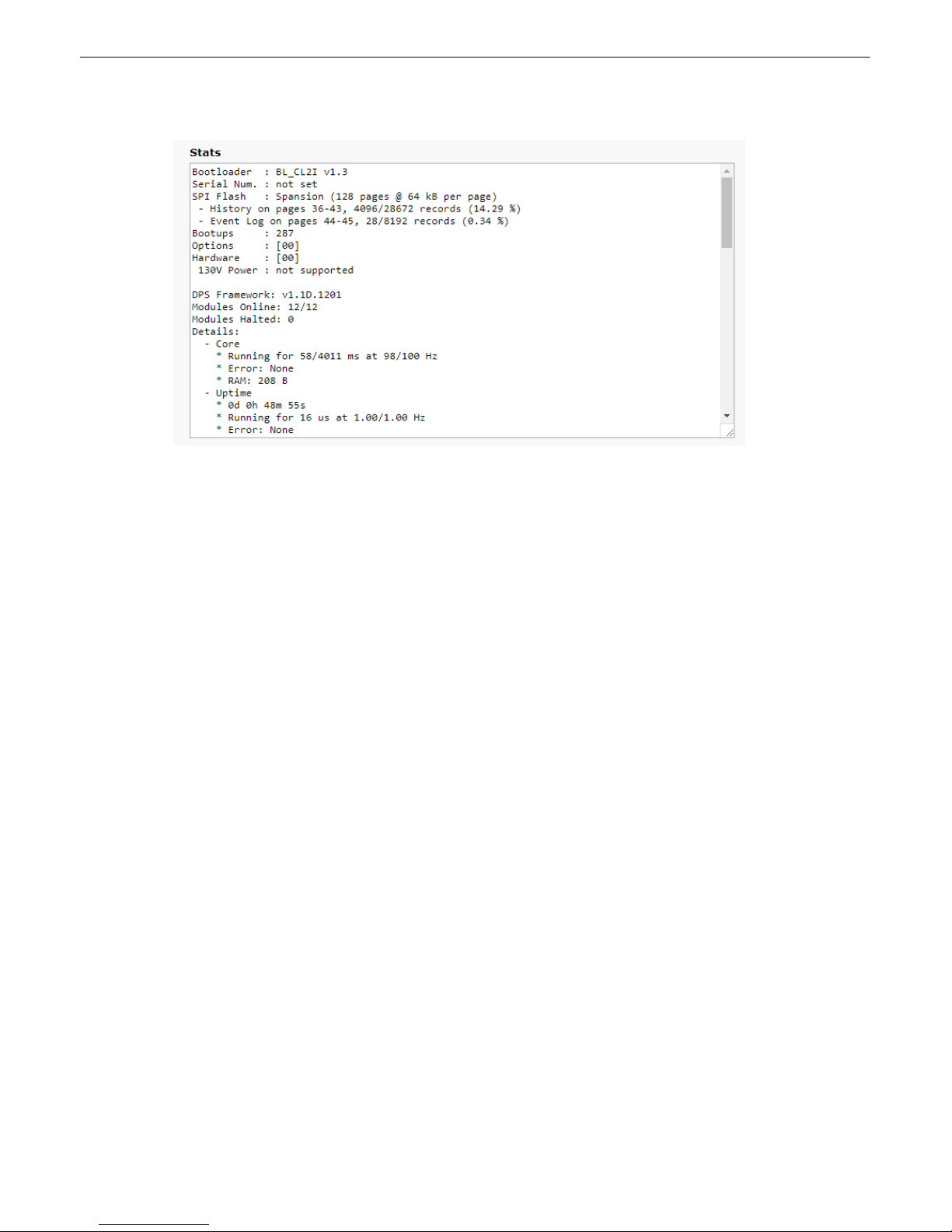
Stats12.4
Page 49
45
Device Access Option
Description
Backup Config
Back s up the units configuration sett ings
Read
Reads a c onfiguration file from t he unit
Write
Commits all c hanges made in the web interface to the Cell 2 Interface's non-volatile
memory
Initialize
Sets t he unit's configurati on to factory default values
Get History
Opens the Cell 2 Interface's event hist ory in Notepad (or another plain tex t editor).
Purge History
Deletes the Cell2 Interface's event history
Reboot
Reboots the Cell2 Interface
13
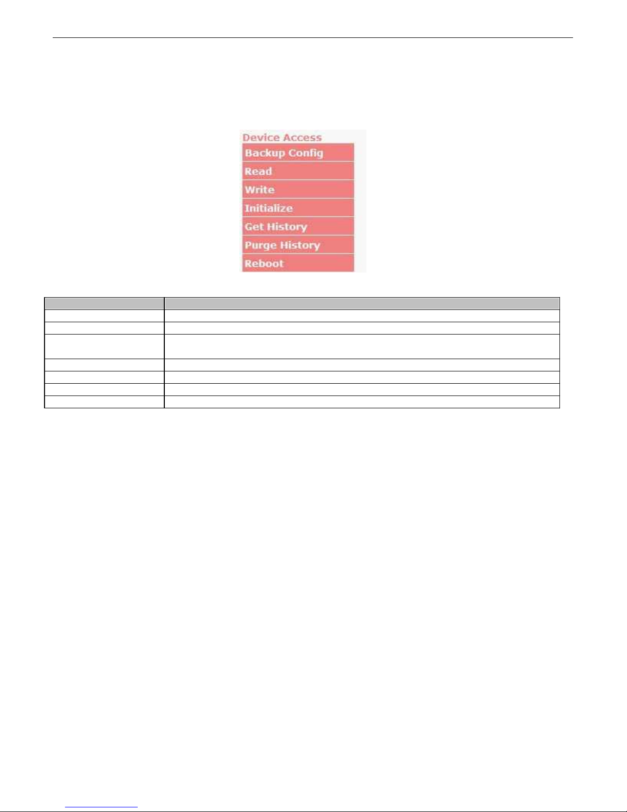
The De vice Access options, listed in pink on the left s ide of the web interface, provide options for generating reports ,
updating the Cell2 Interface's firmware, and rebooting t he unit. Click any of the options under Device Access to
perform the desired ac t i on.
Devi ce Access
The control menu i s loc ated in the b ott om lef t of t he web int erface
Page 50
46
14
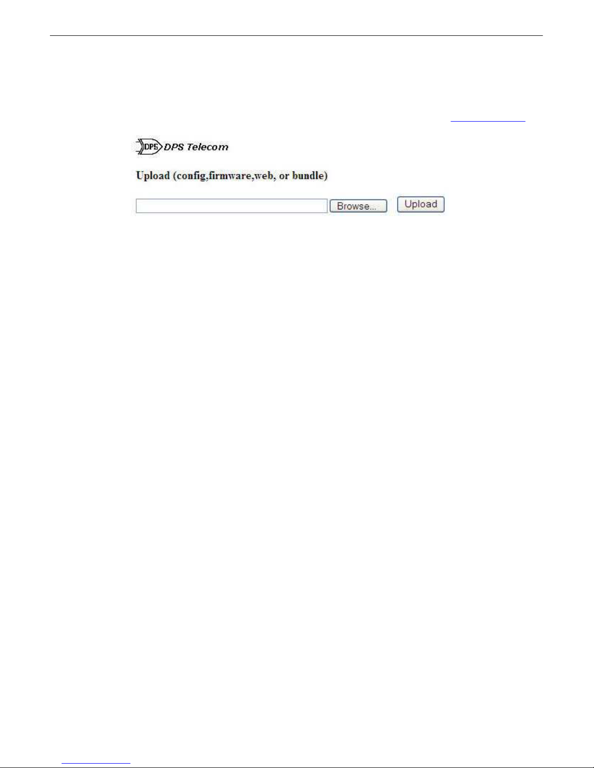
T o access the F i rm wa re Uploa d screen, click on the Upload t ex t in t he top right corner of any page.
At the Firm wa re Uploa d screen, simply bro wse for the firmware update you've downloaded from www.dpstele.com
and click Upload.
Firmware Up g rade
Browse for downloaded f irmware upgrade
Page 51

47
Display
Description
Port
Address
Point
Displa y 1
Discrete A larms 1-4
9911-4
Undefined
9915-32
Defau lt Config uration
99133
DCP Inactive
99134
MAC a ddress not set
99135
SNMP community error
99136
Notification 0 Fai led
99137
Notification 1 Fai led
99138
Notification 2 Fai led
99139
Notification 3 Fai led
99140
Notification 4 Fai led
99141
Notification 5 Fai led
99142
Notification 6 Fai led
99143
Notification 7 Fai led
99144
NT P F ailed
99145
Timed Tick
99146
Seria l 1 RcvQ full
99147
Dyna mic Memory Full
99148
Unit Reset
99149
Modem is not initia lized
99150
Modem is not registered
99151
Modem is not respon ding
99152
Modem ha s ba d signal
99153
Modem failed to sen d SM S
99154
Reserved
99155-62
Cell2 Not Co nfigure d
99163
Cell2 Timed Out
99164
15
Reference Secti o n
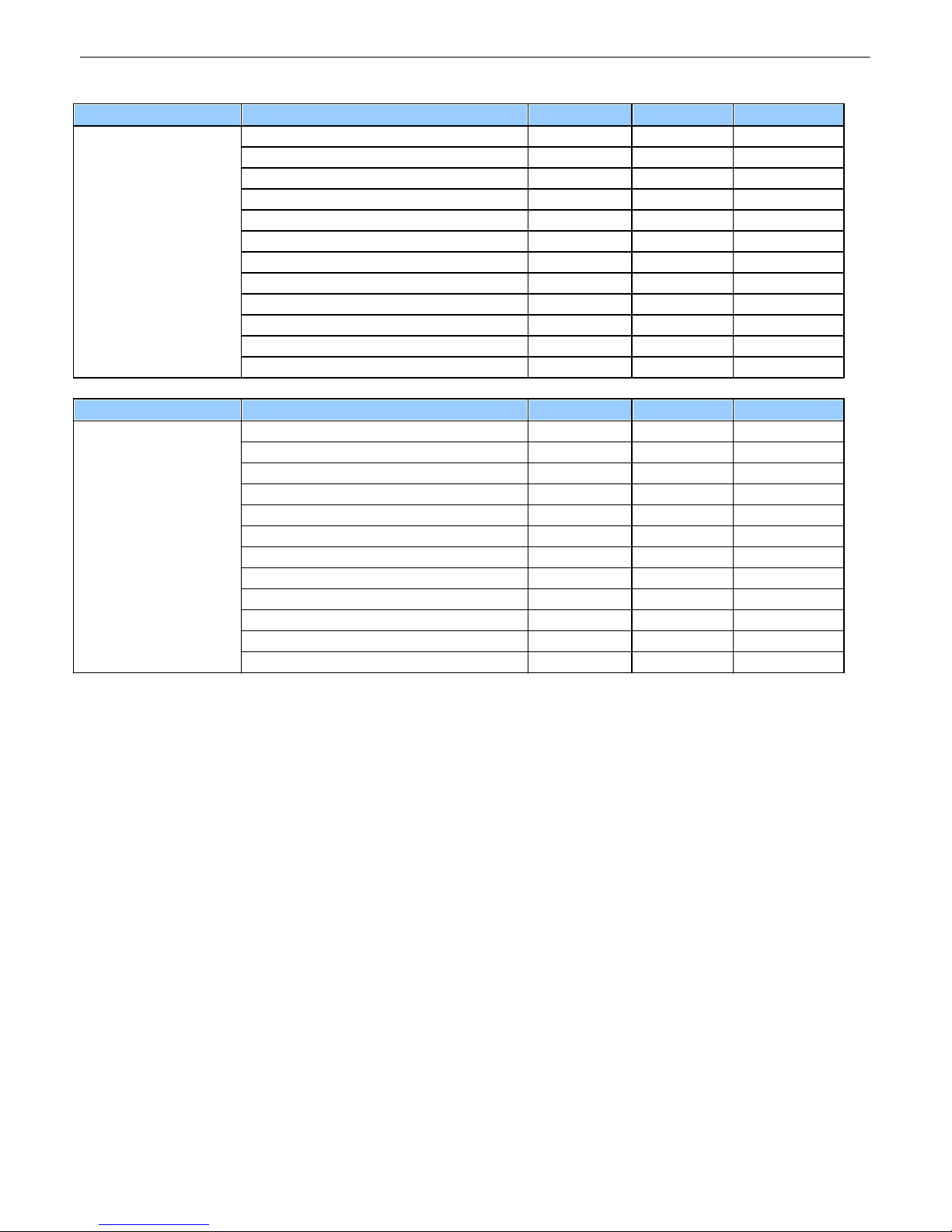
Dis p lay Map15.1
System alarms display map.
Page 52
48
Display
Description
Port
Address
Point
Display 2
A nalog 1 M inor U nder
9911
A nalog 1 M inor Over
9912
A nalog 1 M ajor U nder
9913
A nalog 1 M ajor Over
9914
Control991
9-16
Value991
17-32
A nalog 2 M inor U nder
99133
A nalog 2 M inor Over
99134
A nalog 2 M ajor U nder
99135
A nalog 2 M ajor Over
99136
Control991
41-48
Value991
49-64
Display
Description
Port
Address
Point
Display 3
A nalog 3 M inor U nder
9911
A nalog 3 M inor Over
9912
A nalog 3 M ajor U nder
9913
A nalog 3 M ajor Over
9914
Control991
9-16
Value991
17-32
A nalog 4 M inor U nder
99133
A nalog 4 M inor Over
99134
A nalog 4 M ajor U nder
99135
A nalog 4 M ajor Over
99136
Control991
41-48
Value991
49-64
Page 53
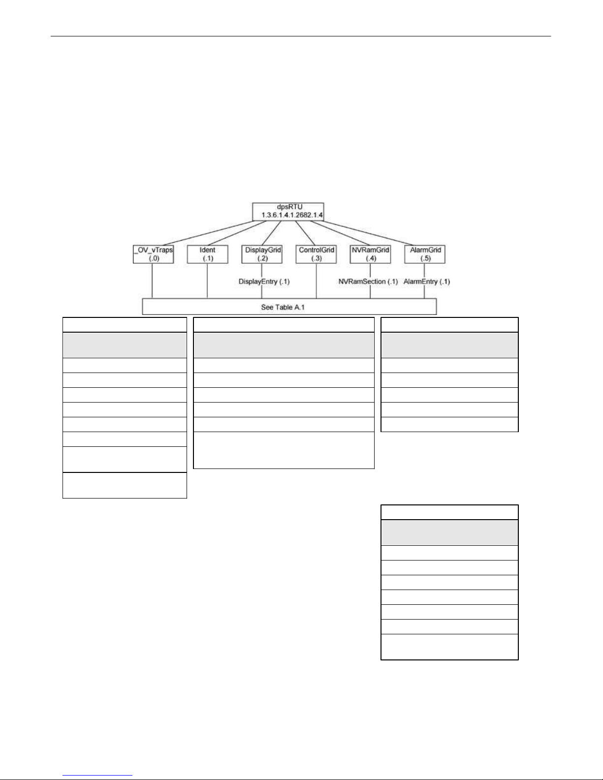
SNMP Manager Fu n ctions15.2
Tbl . B1 (O.)_OV_Traps points
_OV_vTraps
(1.3.6.1.4.1.2682.1.4.0)
PointSet (.20)
PointClr (.21)
SumPSet (.101)
SumPClr (.102)
ComFailed (.103)
ComRestored (.014)
P0001Set (.10001) through
P0064Set (.10064)
P0001Clr (.20001) through
P0064Clr (.20064)
Tbl . B2 (.1) Identity p o i n ts
Ident
(1.3.6.1.4.1.2682.1.4.1)
M anufacturer (.1)
M odel (.2)
Firmware V ersion (.3)
DateTime (.4)
ResyncReq (.5)*
* Must be set to "1" to perform the resync
request which will resend TRAPs for any
standing alarm.
Tbl . B3 (.2) Display Grid p o i n ts
DisplayEntry
(1.3.6.1.4.1.2682.1.4.2.1)
Port (.1)
A ddress (.2)
Display (.3)
DispDesc (.4)*
PntM ap (.5)*
Tbl . B5 (.5) AlarmEntry p o i n ts
AlarmEntry
(1.3.6.4.1.2682.1.4.5.1)
A port (.1)
A Address (.2)
A Display (. 3)
A Point (.4)
A PntDesc (.5)*
A St ate (.6)
* For specific alarm points, see
Table B6
The SNMP Manag er allows the user to view alarm status, set dat e/time, issue controls, an d perform a
resync. The display and ta bles belo w o utline t he MIB o bject identifiers. Ta ble 14. 2 begins with d psRTU;
however, the MIB obje ct ide n ti fi e r tre e ha s severa l l e v e ls abo ve it. The ful l Eng l i sh na me is as follo ws:
root. iso.o rg.dod.internet . private.enterprises.dps-In c.dpsA larmControl.dpsRTU. Therefore, dpsRTU's full
obj ect id entifie r is 1.3 . 6.1.4.1 . 2682.1 . 4. Each lev el beyond dpsRTU adds ano t her object id entifying
number. F or example, the object identifier of the Display porti on of the Control Grid is
1.3. 6.1.4.1 . 2682.1 . 4.3.3 because the obje ct identifier of dp sRTU is 1.3.6.1.4.1.2 682.1.4 + the Contro l
Gri d (.3) + the Displ ay (.3).
49
Page 54
50
UDP Header
Description
1238
Source port
162
Destinat ion port
303
Length
0xBAB0
Checksum
SNMP Header
Description
0
Version
Public
Request
Trap
Request
1.3.6.1.4.1.2682.1.4
Enterprise
126.10.230.181
Agent addres s
Enterprise Specific
Generic Trap
8001
Specific Trap
617077
Tim e s t amp
1.3.7.1.2.1.1.1.0
Object
NetGuardian v1.0K
Value
1.3.6.1.2.1.1.6.0
Object
1-800-622-3314
Value
1.3.6.1.4.1.2682.1.4.4.1.0
Object
01-02-1995 05:08:27.760
Value
1.3.6.1.4.1.2682.1.4.5.1.1.99.1.1.1
Object
99
Value
1.3.6.1.4.1.2682.1.4.5.1.2.99.1.1.1
Object
1
Value
1.3.6.1.4.1.2682.1.4.5.1.3.99.1.1.1
Object
1
Value
1.3.6.1.4.1.2682.1.4.5.1.4.99.1.1.1
Object
1
Value
1.3.6.1.4.1.2682.1.4.5.1.5.99.1.1.1
Object
Rectifier Failure
Value
1.3.6.1.4.1.2682.1.4.5.1.6.99.1.1.1
Object
Alarm
Value
SNMP Granular Trap Pack ets15.3
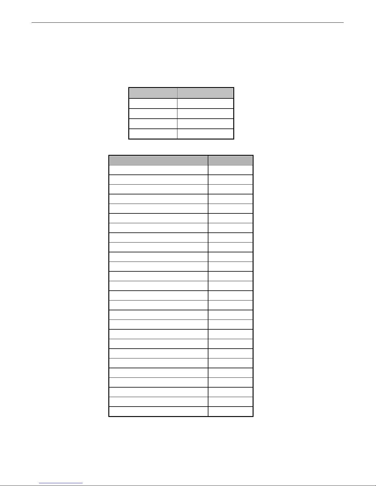
SNMP Trap ma na gers can us e one of two methods to get alarm information:
1.Granu l ar tra ps (not ne cessary to de fi ne po in t de scriptio n s for the Cell 2 I n te rfa ce) OR
2.The SNM P man ager reads the description from the T rap.
UDP Headers and des criptions
SNMP Headers and des c riptions
Page 55

51
16
Here are answers t o s ome comm on questions from Cell2 Interface us ers. The latest FAQs can be found on t he Cell2
Inter f ace suppor t web page , http://www.dpstele.com.
If you have a question about the Cell2 Interface, please call us at (559) 454-1600 or e-mail us at
Frequently Asked Questions
General FAQs16.1
Q. How do I telnet to the Cell2 Interface?
A. Y ou must use Port 2002 to conn ect to the Cell2 Interface. Confi gure yo ur Telne t client to conn ect
using T CP/IP (not " T elnet," or any other port option s). Fo r con nection information , enter the IP
add ress of the Ce ll2 Interface a nd Port 20 02. For example, to connect to the Ce l l2 I nterface using
the standard Windo ws Tel net client , cli ck St art, click Run, a nd type "teln et <Cell2 Interf ace IP
add ress> 2002."
Q. How do I connect m y Cell2 Interface to LAN?
A. To con nect your Cell2 Interfa ce to your L AN, you ne ed to confi gure the unit IP address, the subn et
mask and t he defa ult gateway. A sample con f igurati on could l ook li ke this:
Unit Address: 192.168.1.100
subnet mask: 255.255.255.0
Default Gateway: 192.168.1.1
Save your changes by writing to NVRAM and re boot. Any change to the unit 's IP conf igurati on
requ ires a reboo t .
Q. When I co n nect to the Cell2 Interface through the craft port on th e front pan el it either
doesn't work rig h t o r it d o esn't wo rk at all. What's going o n ?
A. Make sure you're usin g the rig ht COM port sett ings. Your COM port settings should read:
Bits per second: 115200 baud
Data bits: 8
Parity: None
Stop bits : 1
Flow control: None
Important! Flow control must be set to none. Flow control normally defaul t s to hardware i n most
termina l programs, and t his will not work corre ctly with the Cell2 Inte rf ace.
Q. The LAN link L ED is green on m y Cell2 Interface, but I can't poll it from m y T/Mon.
A. Some rout ers will not forward packets to an IP ad dress until the MAC address of the destinat ion
device has been registered on the router's Ad dress Resolution Protocol (ARP) table. Enter t he I P
add ress of yo ur gateway and y our T/Mon system to the ARP table.
Q. I'm unsure if the voltage of my p o wer suppl y is within the specified range. How to I test the
voltage?
A. Connect the black common lea d of a voltmeter to the ground terminal of the battery . Co nnect the re d
lea d of the voltmeter t o the ba t t ery's VCD termina l. The v oltmeter shoul d read between +12 and
+30VDC.
Page 56

52
SNMP FAQs16.2
Q. Which version o f SNMP is s u p p o rted by the SNMP agent on the Cell2 In terface?
A. SNMP v1 and v2c.
Q. How do I configure the Cell2 Interface to send traps to an SNMP manager? Is there a
separate MIB for the Cell2 I n terface? How many SNMP managers can th e agent send traps
to? And h o w do I set the IP address of the SNMP manager and the community string to b e
used when sending tra p s?
A. The Ce ll2 Interfa ce b egins sending traps as soon as the SNMP manag ers are d efined . T he Cell2
Interface MIB is includ ed on th e Cell2 Interf ace Resource CD. Th e MIB should be compiled on y our
SNMP manager. (Note: MIB versio ns may chan ge in th e future. ) The unit sup ports 2 SNMP
managers, which a re configured by entering it s IP address in the T rap Address fie ld of Ethernet Port
Setup. To configure the community strings, choose SNM P f rom the Edit menu, a nd ente r
app ropriate value s in t he Get , Set, and T rap fields.
Q. Does the Cell2 Interface support MIB-2 and / o r a n y other stand ard MIBs?
A. The Ce ll2 Interfa ce supports the bu lk of MIB-2.
Q. Does the Cell2 Interface SNMP agent supp o rt bo th Cell2 In terface and T/MonXM variables?
A. The Ce ll2 Interfa ce SNMP agent manages an e mbe dded MIB that supports only t he Cell2 Interface's
RTU variab les. The T/MonXM va riables are included in the d istributed MIB only t o provi de SNMP
managers with a sing le MIB f or all DPS Tel ecom prod ucts.
Q. How many traps are triggered wh en a s i n g l e point i s set or cleared? The MIB defines traps
like "major alarm s et/cleared," "RTU point set," and a lot of granular traps , which c o u l d i mply
that more than one trap is s ent w h en a c h ange of sta te occurs on one point.
A. Ge nerally, a singl e chan ge of state generat es a sing le trap.
Q. What does "point map" mean?
A. A point map is a sing l e M IB le af that p resents the current status of a 64-alarm-po int displa y in an
A SCII-reada ble form, where a "." represents a clear and an "x" repre sen t s an alarm.
Q. How c an I asso ciate descripti ve information wi th a point for the RTU granular trap s?
A. The Ce ll2 Interfa ce a larm point descripti ons are ind ividu ally d efined using the Web Browser.
Q. My SNMP traps aren't getting throu g h . What s h o u l d I try?
A. Try these three steps:
1. Make sure t hat the T rap Address (IP addre ss of the SNMP manag er) is defined. (If you cha nged
the T rap Address, make sure you saved the change to NVRAM and rebooted.)
2. Make sure all alarm poi nts are configured to send SNMP trap s.
3. Make sure t he Cell2 Interface and t he SNMP manager are both on the network. Use th e unit's
pin g command to ping th e SNMP manager.
Page 57

53
17
DPS Tele com products are backed by our courte ous, friend l y Technical Support re presentati ves, who
will give you the best in fast an d accurate customer service. To help us hel p you b etter, pl ease take t he
following step s be f ore callin g Technical Su pport:
1. Check the DPS Telecom websi te.
Technical Sup p o rt
Y o u wil l fi n d a nswers to many common q ue stio n s on the DPS Tele com website, at http://
www.dpstele.com/support/. Look here first for a fast solution to your p roblem.
2. Prepare relevant information .
Having important informati on abou t your DPS Tel ecom prod uct in hand whe n you call will gre atly
redu ce the time it takes to an swer y our questions. If you do not have all o f t he info rmation when you
call, o ur Technical Su pport rep resentatives can assist you in gath ering it . Please write the info rmation
down f or easy access. Please ha ve your user manual and hardware serial number read y.
3. Have access to troubl ed equipment.
Plea se b e at or ne ar your e quipment wh en you cal l DPS Telecom Technical Support. T his will help us
solve your pro blem more efficiently.
4. Call d u rin g Custom er Support hou rs .
Customer support hours are Monday through Fri day, fro m 7 A.M. to 6 P. M., Pacific time. T he DPS
Tele com Techni cal Suppo rt phon e number is (559) 45 4-1600.
Em ergency A ssistance: Emerge ncy assistance i s available 2 4 hours a da y, 7 days a week. For
emergency assistance af t er hours, allow the phone t o ring until it i s an swered with a paging message.
You will be asked to e nter your phone numbe r. An on-call techni cal support represent ative will return
your call a s soon as possible.
Page 58

54
18
All Software and firmware used in, for, or in connection with the Product, parts, s ubs y s t ems , or derivatives t hereof, i n
whatever form, including, without limitat ion, s ource code, object code and microcode, including any computer
programs and any documentation relating to or desc ribing such Software is furnished to the End User only under a
non-exclusive perpetual license solely for End User's use with the Product.
The Software m ay not be copied or modified, in whole or in part, for any purpose whatsoever. The Software may not
be reverse engineered, c ompiled, or disass embled. No tit le to or ownership of the Soft ware or any of its parts is
transferred to the End User. Tit le t o all patents, c opyrights , t rade secrets, and any other applic able rights s hall
remain wit h the DPS Telecom.
DPS Tel ecom's warrant y and limit ati on on its li ability for t he Software is as desc ribed in the warranty informat i on
provided t o End User in the Produc t M anual.
End User shall indemni fy DPS Telecom and hold it harmless for and against any and all claims , damages, los s es ,
cost s , ex penses, obligations, li abiliti es, fees and costs and all amounts paid in settlement of any claim, act i on or
suit which may be ass erted against DPS Telecom which arise out of or are related to the non-fulfillment of any
covenant or obligation of End User in connection with this Agreement.
This A greement shall be construed and enforc ed in acc ordance with the laws of the State of Cali fornia, wit hout
regard to choic e of law principles and exc luding the provisions of the UN Convent ion on Cont ract s for the
International Sale of Goods. A ny dis pute arising out of t he Agreement shall be commenced and m aintained only in
Fresno County , California. In the event suit is brought or an att orney is retained by any party to this A greement to
seek interpretation or construction of any t erm or provision of t his A greement, to enforc e the terms of this
Agreement , t o c ollec t any money due, or to obtain any m oney damages or equit able relief for breach, t he prevailing
party shall be entitled to recover, in addition to any ot her available remedy, reimbursement for reasonable at t orneys'
fees , c ourt c ost s, c os t s of investigation, and other related expenses.
End User License Agreemen t
Page 59

Warranty
DPS Telecom w ar r ants, to the original purchaser only, that its products a) substantial ly conform to DPS' published
specifications and b) are substantiall y free fr om defects in m aterial and workmanship. This warranty expires two years from the
date of product deli very wi th respect to hardware and ninety days from the date of product delivery with respect to software.
If the purchaser discovers within these periods a failure of the product to substantiall y conform to the specif ications or that
the product is not substantiall y free fr om defects in m aterial and workmanship, the purchaser must promply notify DPS . Within
reasonable tim e after notif ication, DPS will endeavor to correct any substantial non-conformance with the specifications or
substantial defects in m aterial and workmanship, with new or used replacement parts. All warranty service wil l be performed at
the company's offi ce i n Fresno, Cal ifornia, at no charge to the purchaser, other than the cost of shipping to and from DPS,
which shall be the responsibli ty of the purchaser. If DP S is unable to repair the product to conform to the warranty, DP S will
provide at its option one of the following: a replacement product or a refund of the purchase pri ce for the non-conforming
product. These remedies are the purchaser's only remedies for breach of warranty. Prior to initial use the purchaser shall have
determined the suitabili ty of the product for its intended use. DPS does not warrant a) any product, components or parts not
m anufactured by DPS, b) defects caused by the purchaser's failure to provide a suitable installation environment for the
product, c) damage caused by use of the product for purposes other than those for which it was designed, d) damage caused
by disasters such as fi re, flood, wind or lightning unless and to the extent that the product specif ication provides for
resistance to a defined disaster, e) damage caused by unauthorized attachments or modifications, f) dam age during shipment
from the purchaser to DPS, or g) any abuse or misuse by the purchaser.
THE FOREGOING WARRANTIES ARE I N LIEU OF AL L OTHER WARRANTIES, EXPR ESS OR IMPLIED, I NCL UDING B U T
NOT LIMITE D TO THE IMPLIED WARRANTIES OF MERCHANTABILITY AND FITN ESS FO R A PARTICUL AR
PURPOSE.
In no event will DPS be li able for any special, incidental, or consequential damages based on breach of w arr anty, breach of
contract, negligence, strict tort, or any other legal theory. Dam ages that DPS will not be responsible for i nclude but are not
limited to, loss of profits; loss of savings or revenue; loss of use of the product or any associated equipment; cost of capital;
cost of any substitute equipment, facilities or services; downtime; claims of third parties including custom er s; and injury to
property.
The purchaser shall f ill out the requested information on the Product Warranty Card and m ai l the card to DPS. This card
provides information that helps DPS make product improvements and develop new products.
For an additional fee DP S may, at its option, make avail able by written agreement only an extended warranty providing an
additional period of time for the appli cabil ity of the standard warranty.
Technical Support
If a purchaser believes that a product is not operating in substantial conform ance with DPS' published specifications or there
appear to be defects in material and workmanship, the purchaser should contact our technical support representatives. If the
problem cannot be corrected over the telephone and the product and problem are covered by the warr anty, the technical
support representative wil l authorize the return of the product for service and provide shipping information. If the product is
out of warranty, repair charges will be quoted. All non-w arr anty repairs receive a 90 -day warranty.
Page 60
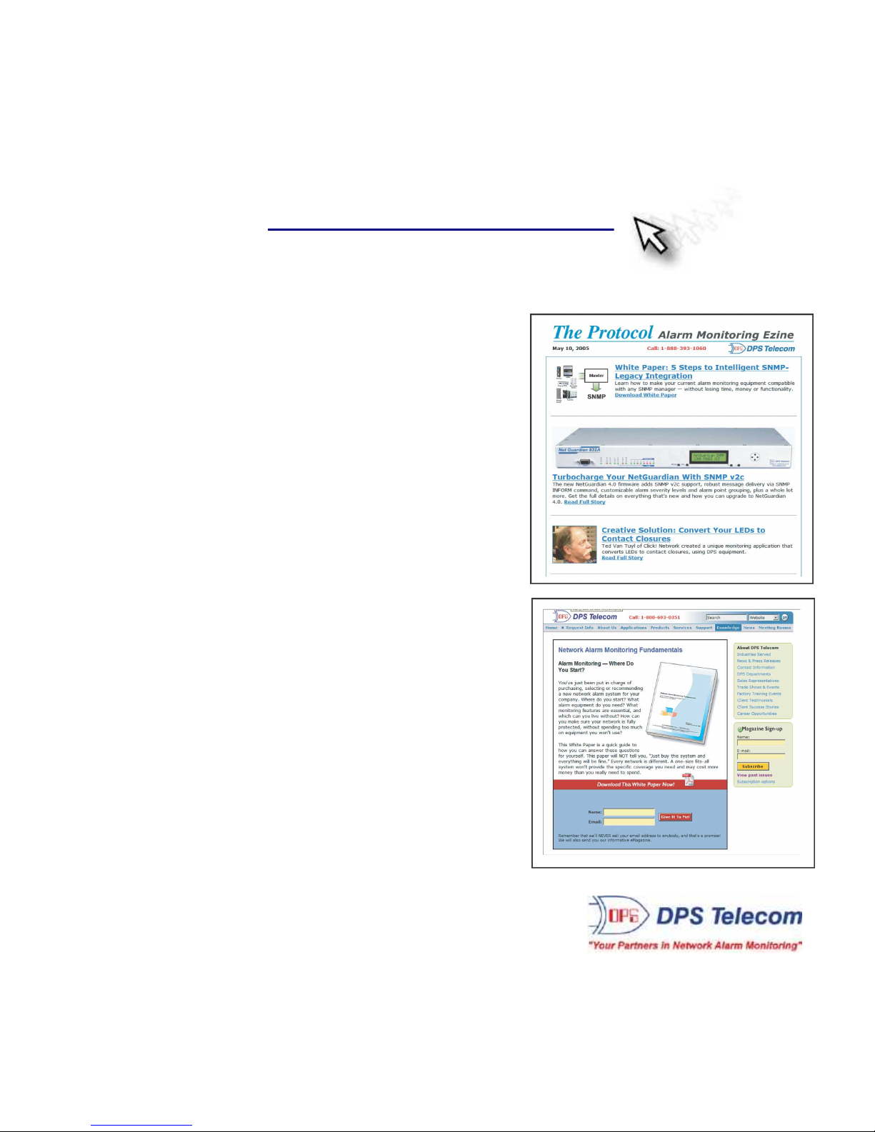
Free Tech Support is Onl y a Click Away
Need help with your alarm monitorin g? DPS Informati on Serv ices are ready to
serv e you … in your email or over the Web!
www.DpsTelecom.com
Free Tech Support i n Y our Email : The Protocol A l arm Monit ori ng Ezine
The Protocol Alarm Monito ring Ezine is your free e mai l
tech support alert, deliv ered directly t o your i n-box
every two weeks. Every issue has news yo u can use
righ t away:
Expert tips on u sin g your a larm monit oring
•
equ ipment — advanced te chn iques that wi ll save
you hours of work
Educati onal White Papers deli ver fast inf ormal
•
tuto rials on SNM P, ASCII processing, TL1 and
other alarm monito ring technologies
New product an d upgrade announcements kee p
•
you up to d ate with the late st te chn ology
Exclusiv e access to special of f ers for DPS
•
Telecom Factory T raining , product upgrade of f ers
and discoun t s
To get your free subscription to
The Protocol register online at
www.TheProtocol.com/register
Free Tech Support on the Web: MyDPS
MyDPS is your personal ized, members-on ly onl ine resource.
Registering for My DPS i s fast, free, and gives yo u exclusive
access to:
• Firmware and software downloads and upgrades
• Prod uct manua ls
• Prod uct dat asheets
• Exclu sive user forms
Register for MyDPS online at
www.DpsTelecom.com/register
(800) 622-3314 • www . DpsTele com . com • 4955 E. Yal e Avenue, Fresno, Cali fornia 93727
 Loading...