

Page 1
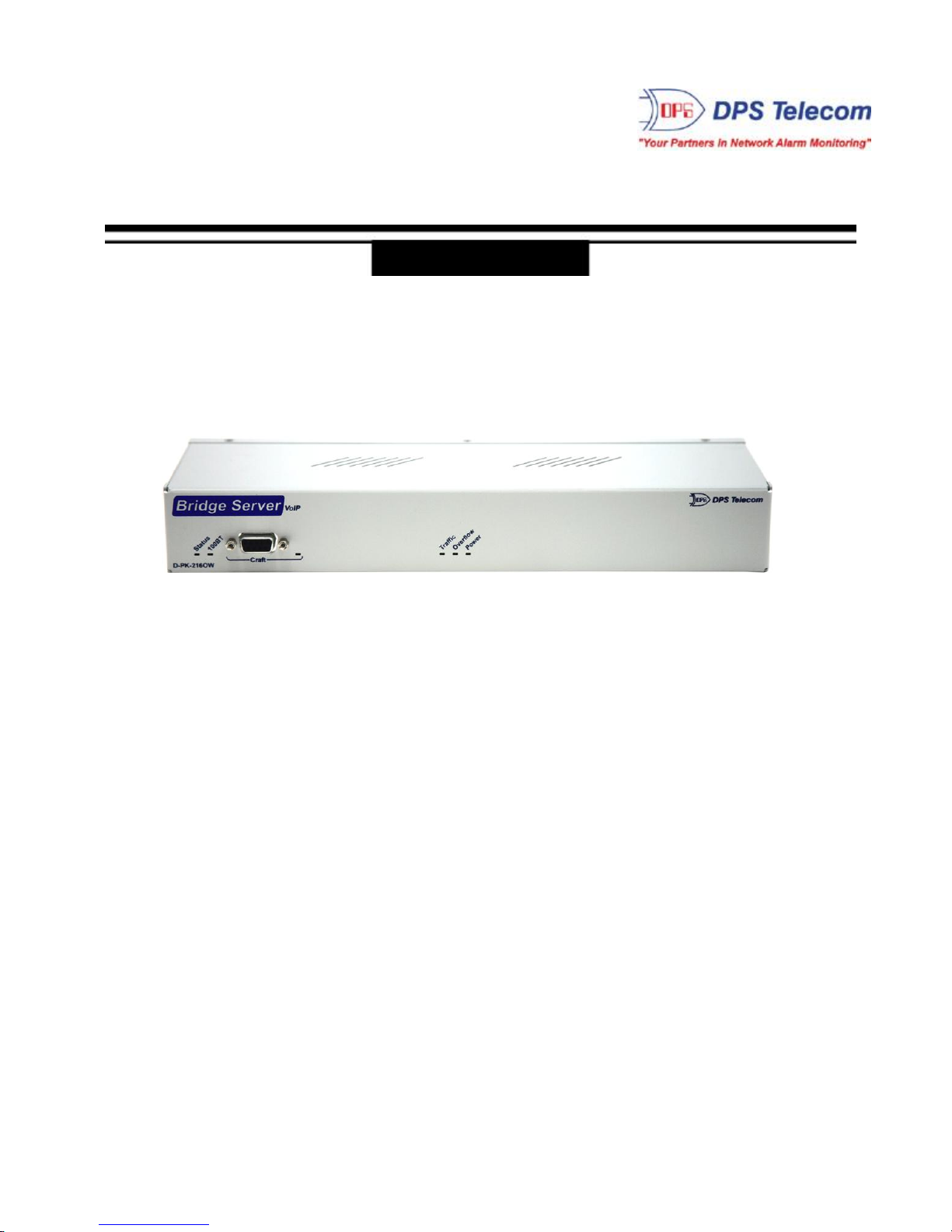
VoIP Bridge Server
USER MANUAL
Visit our website at www.dpstelecom.com for the latest PDF manual and FAQs.
June 24, 2015
D-OC-UM10A.18100 Firmware Version 2.0A
Page 2

Revision History
June 24, 2015
Oct. 18, 2010
Sept. 30, 2010
Firmware note added
Updated Overview and LED descriptions.
Initial Release.
This document contains proprietary information which is protected by copyright. All rights are reserved. No part of this
document may be photocopied without prior written consent of DPS Telecom.
All software and manuals are copyrighted by DPS Telecom. Said software and manuals may not be reproduced, copied,
transmitted or used to make a derivative work, by either mechanical, electronic or any other means in whole or in part, without
prior written consent from DPS Telecom, except as required by United States copyright laws.
© 2015 DPS Telecom
Notice
The material in this manual is for information purposes and is subject to change without notice. DPS Telecom shall not be
liable for errors contained herein or consequential damages in connection with the furnishing, performance, or use of this
manual.
Page 3

Contents
Visit our website at www.dpstelecom.com for the latest PDF manual and FAQs
VoIP Bridge Server Overview1 1
Specifications2 3
Shipping List3 4
Optional Shipping Items3.1 5
Installation4 5
Tools Needed4.1 5
Mounting4.2 6
VoIP Bridge Server Back Panel5 8
Power Connection (+12 or +24VDC Build Option)5.1 9
Power Connection (-48 or -24VDC Build Option)5.2 10
LAN Connection5.3 10
VoIP Bridge Server Front Panel6 11
Craft Port6.1 11
Front and Back Panel LEDs7 12
How to Set Up the VoIP Bridge Server8 13
Set Bridge Server IP via Craft Port (using TTY Interface)8.1 13
Add the Bridge Server to your Order Wire Configuration8.2 15
Dial into the Bridge Server from Order Wire stations8.3 17
How to Upgrade Firmware Via LAN9 18
Frequently Asked Questions10 19
General FAQs10.1 19
Technical Support11 20
End User License Agreement12 21
Page 4

Page 5
1
1
The VoIP Order Wire system from DPS Telecom is an effective way for technicians to communicate
between sites. Sometimes, however, you need to host a "conference call" across multiple VoIP
stations.
You need a simple device that will support this "conference call" functionality without needing to
broadcast packets across your network.
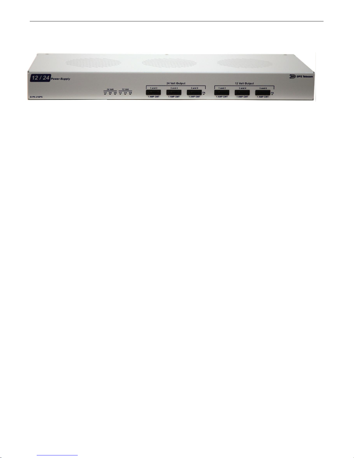
Meet the VoIP Bridge Server
This small device will bridge up to 5 VoIP Order Wire stations into a single conference call. Voice data
from individual stations is sent only to other stations connected to the bridge, rather than being
broadcast across the network. VoIP users simply follow the voice prompt at their station to dial into the
VoIP Bridge Server and join any other connected users on a conference call. Whenever a user enters
or leaves the call, all other connected users will hear an automated announcement.
VoIP Bridge Server Overview
Your VoIP Conference Bridging Solution
Page 6
2
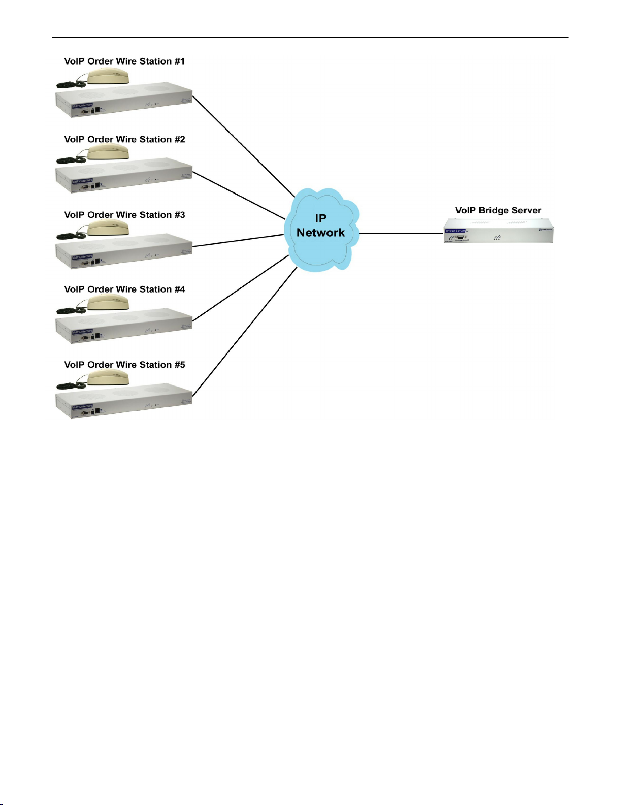
Up to 5 VoIP Order Wire stations may connect via IP to a single VoIP Bridge Server in order to
hold a conference call.
Note: Firmware version 2.0A.0026 or higher could support up to 10 VoIP stations.
Page 7

3
2
Protocols: Telnet, RTP, HTTP
Dimensions: 1.720" H x 11.5" W x 4" D
Weight: 1.5 lbs.
Mounting: 19" rack or wall mount
Power Input: -48VDC (-36 to -72 VDC)
Current Draw: 100 mA @ -24VDC
Fuse: Resettable Fuse (Internal), if +24V Power Input
Interfaces: 1 RJ45 10/100BaseT Ethernet port
Visual Interface: 6 Front Panel LEDs
Specifications
+24 VDC via 110VAC wall transformer (12 V to 30 VDC, Optional)
-24VDC (Optional)
50mA @ -48VDC
1/2 Amp GMT Fuse, if -48V or -24V Power Input
1 DB9 front-panel craft port
4 Back Panel LEDs
Operating Temperature: 32°–140° F (0°–60° C)
Operating Humidity: 0%–95% non-condensing
RoHS: 5/6
Page 8
4
3
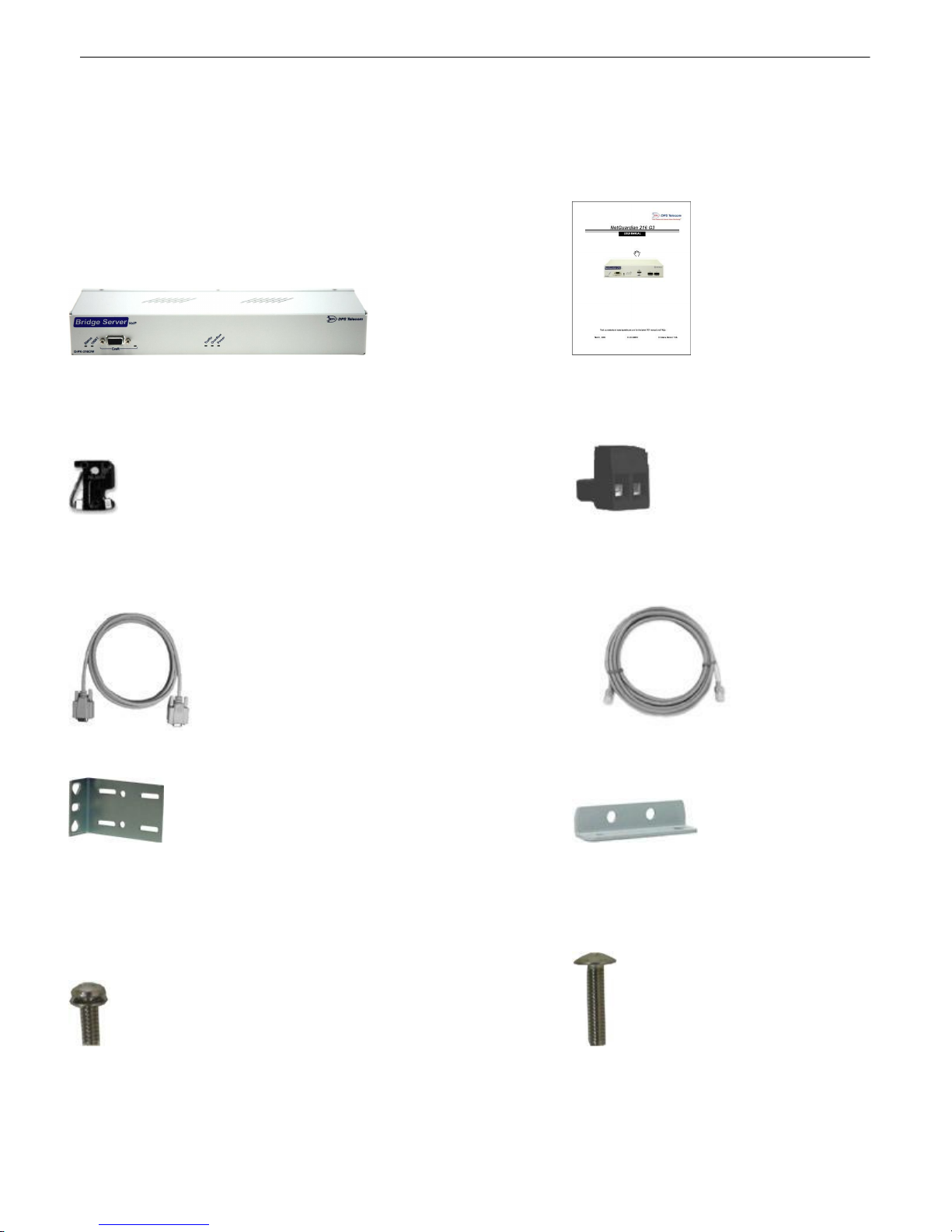
Please make sure all of the following items are included with your VoIP Bridge Server. If parts are
missing, or if you ever need to order new parts, please refer to the part numbers listed and call DPS
Telecom at 1-800-622-3314.
VoIP Bridge Server VoIP Bridge Server User Manual
D-PK-NG216 D-OC-UM10A.18100
½-Amp GMT Fuses Lg. Power Connector (Main Pwr)
(For -48V units only) (For -48V units only)
2-741-00500-00 2-820-00862-02
Shipping List
x 2
6 ft. DB9M-DB9F Download Cable 14 ft. Ethernet Cable
D-PR-045-10A-04 D-PR-923-10A-14
x 2
19" Rack Ear Wall Mount Bracket
D-CS-325-10A-00 D-CS-532-10A-05
x 4 x 2
Four 3/8" Ear Screws Two Metric Rack Screws
1-000-60375-05 2-0008075-03
Page 9
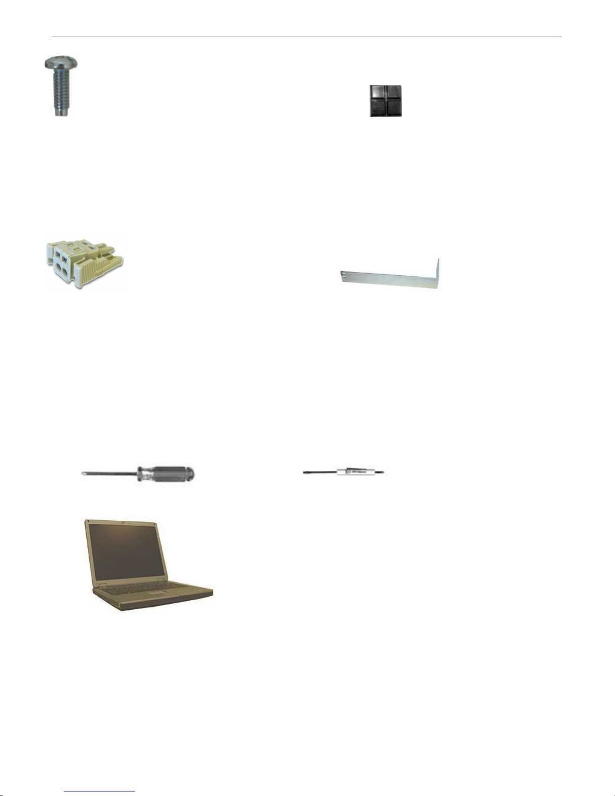
x 2
Two Standard Rack Screws Pads
1-100-12500-06 2-015-00030-00
Optional Shipping Items3.1
Small WAGO connector Long 19" Rack Ear
2-802-01020-00 (D-CS-325-10A-10)
5
4
Installation
Tools Needed4.1
To install the VoIP Bridge Server, you'll need the following tools:
Phillips No. 2 Screwdriver Small Standard No. 2 Screwdriver
PC with terminal emulator, such as HyperTerminal
Page 10
6
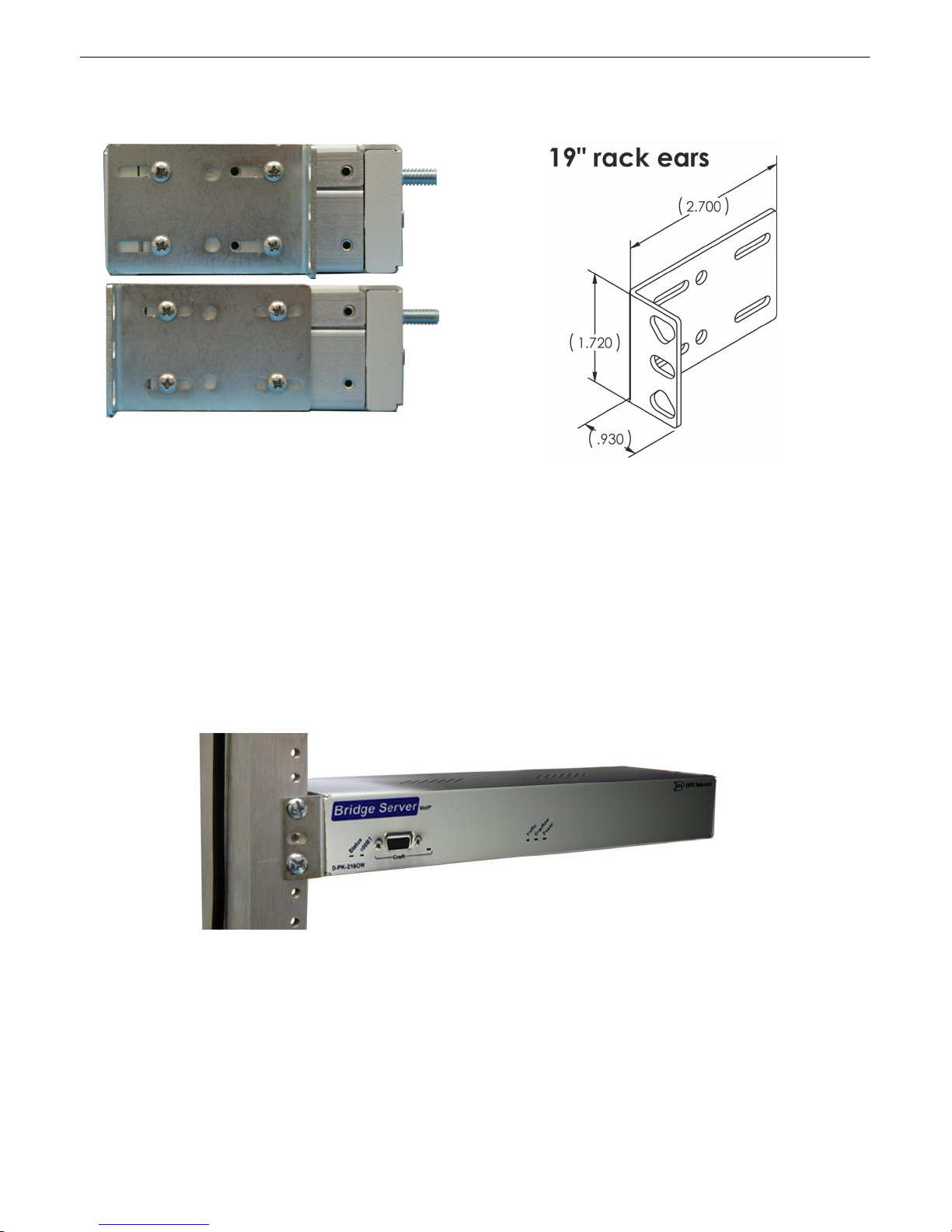
The VoIP Bridge Server can be flush- or rear-mounted
The dimensions (in inches) of the supplied 19" rack
ears.
Mounting4.2
Rack-Mounting Instructions
The compact VoIP Bridge Server occupies only half the width of a standard rack unit. Unless you
ordered a second "long" ear (not shown), only one rack ear is supplied with the VoIP Bridge Server. The
single rack ear can be mounted on the left or right side of the unit. The VoIP Bridge Server mounts in a
19" rack, and can be mounted on the right or left, in the flush-mount or rear mount locations, as shown
in the above image.
As shown below, the VoIP Bridge Server mounts onto one side of a 19" rack using the provided rack ear
for either size. The ear can be rotated 180 degrees during installation to adjust the position of the unit
relative to the rack. Attach the appropriate ear to the rack in the desired location.
The VoIP Bridge Server also mounts on your 19" equipment racks.
Wall-Mounting Instructions
The rack ears can be rotated 90° for wall mounting (shown below) or 180º for other mounting options
(not shown).
1. Depending on your order options, you will attach wall-mount flanges to both sides of the unit.
a. Fasten the flange to the VoIP Bridge Server with two of the 6/32 screws provided. (NOTE: Screws
longer than those provided may contact the internal components of the unit, adversely affecting its
Page 11
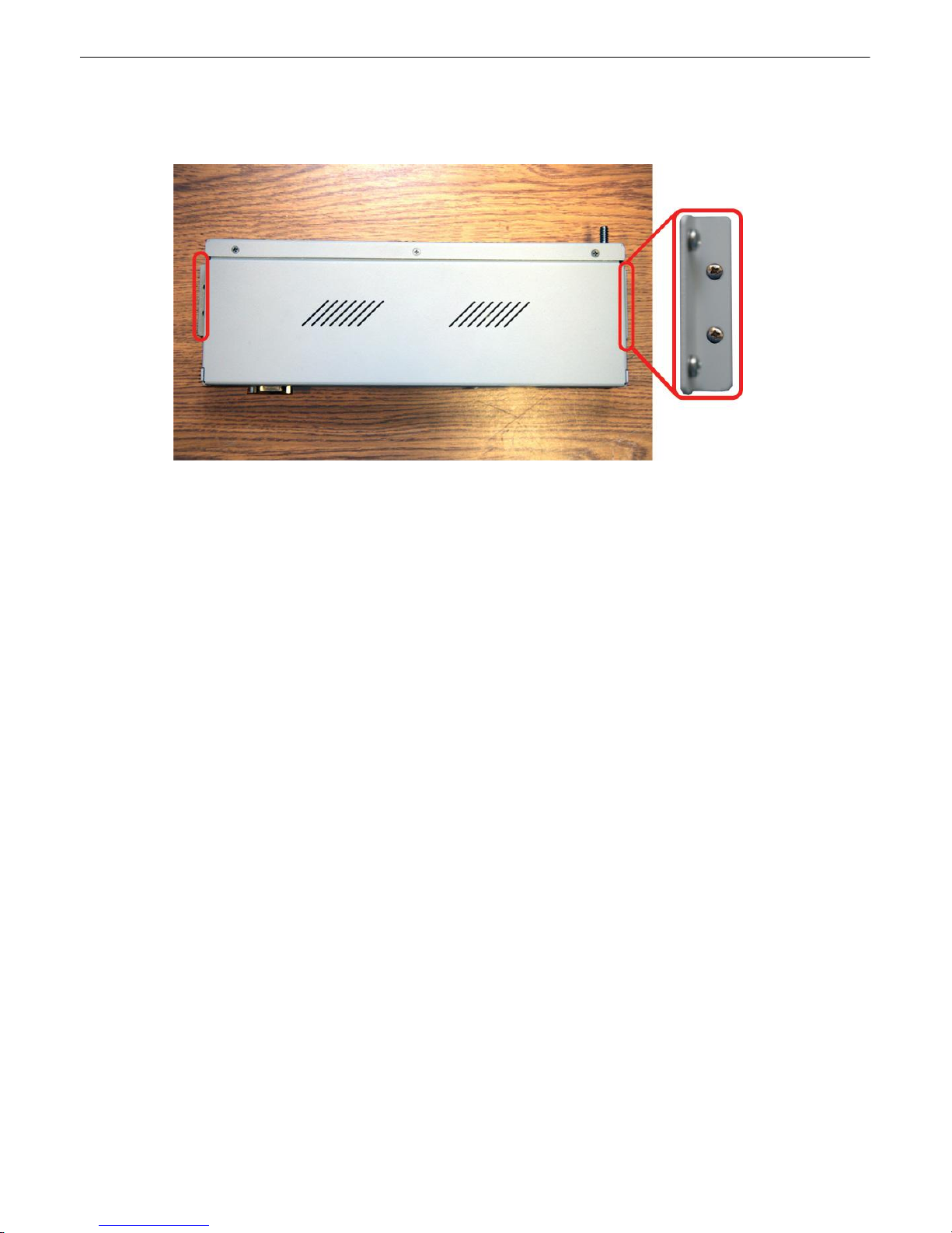
normal operation.)
2. After flanges have been attached to the VoIP Bridge Server, mount the unit in the desired location
with two screws through each flange.
Use the included wall mount bracket to mount the VoIP Bridge Server vertically on the wall.
7
Page 12
8
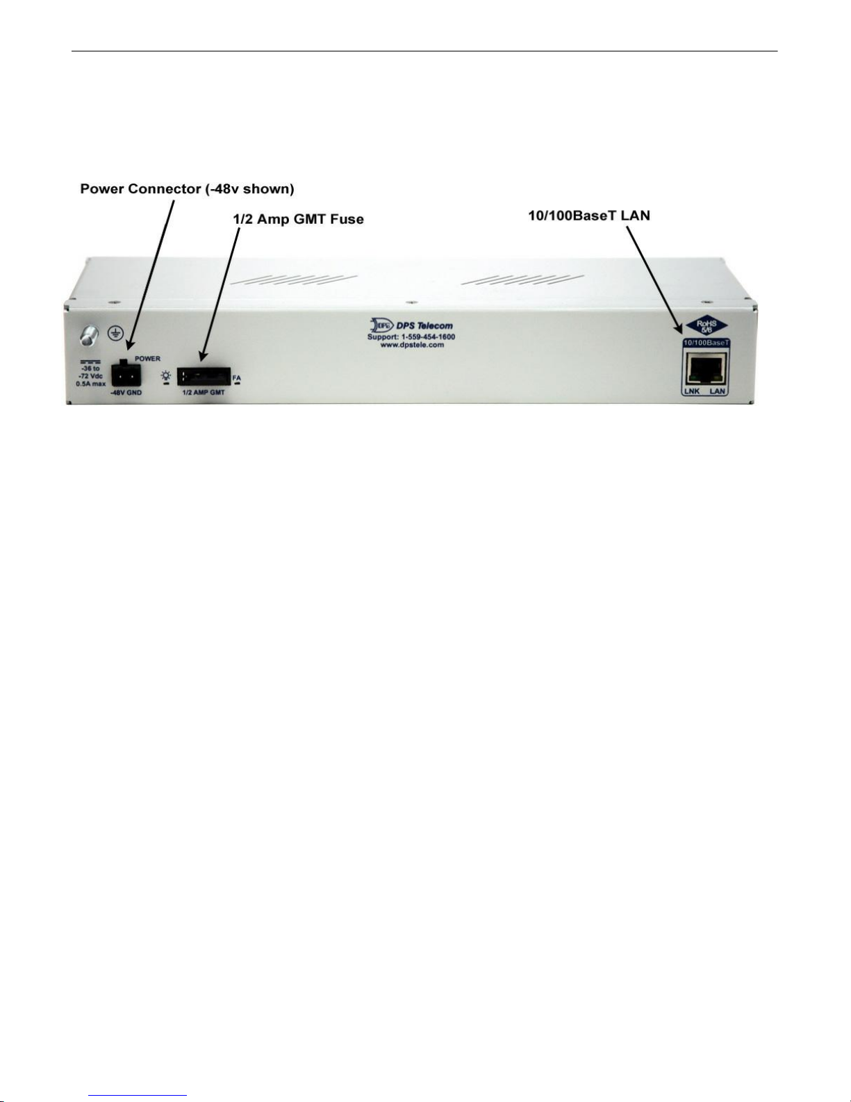
5
VoIP Bridge Server Back Panel
VoIP Bridge Server back panel connections
Page 13
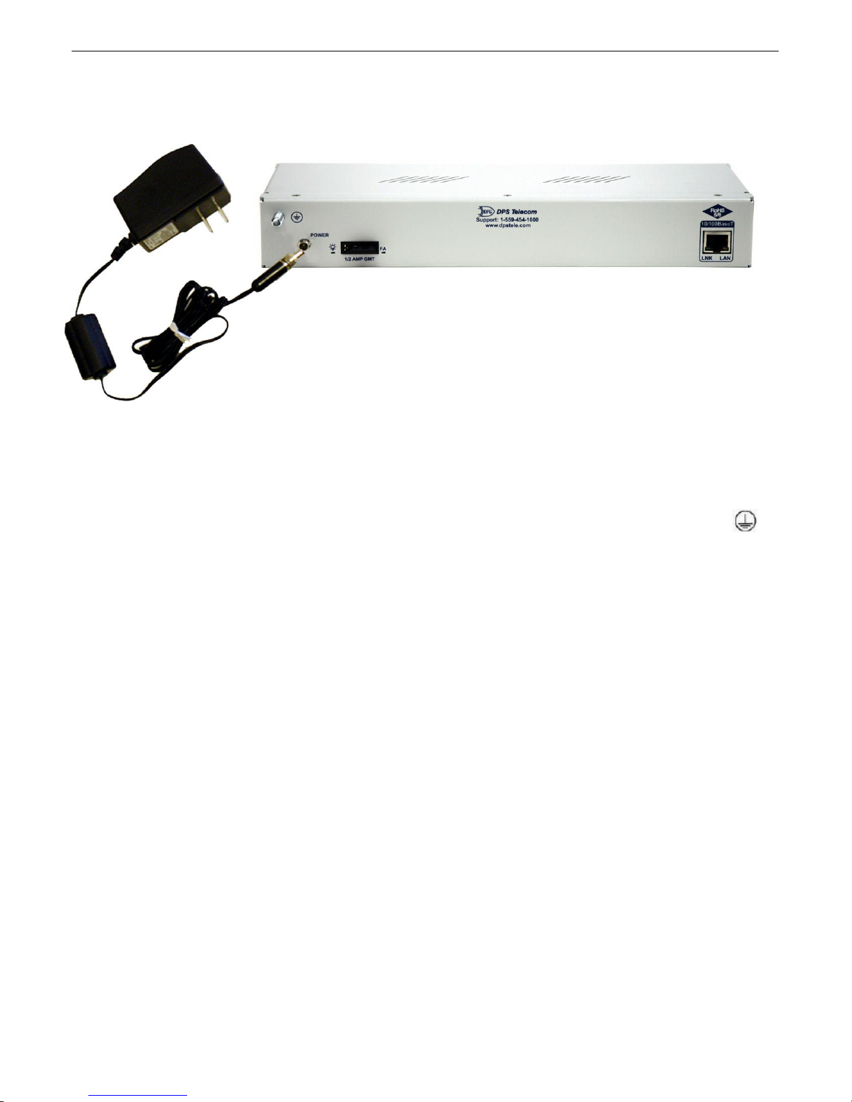
Power Connection (+12 or +24VDC Build Option)5.1
The VoIP Bridge Server is powered by a screw-on plug, located on the right side of the back panel.
Close-up view of VoIP Bridge Server's screw-on power connector.
Before you connect a power supply to the VoIP Bridge Server:
9
1. Always use safe power practices when making power connections. Be sure to remove fuses from
the back of the VoIP Bridge Server before making your power connections.
2. Use the grounding lug to connect the unit to earth ground. The grounding lug is next to the symbol
. Insert the eyelet of the earth ground cable between the two bolts on the grounding lug (Ground cable
not included.)
3. Plug in the power connector to the rear panel of the VoIP Bridge Server. Twist the collar of the plug to
lock in place.
4. Plug in the wall transformer to a power outlet. The power LED should be lit green. To confirm that
power is correctly connected, the front panel LEDs will flash RED and GREEN, indicating that the
firmware is booting up.
Page 14
10
5.
Power Connection (-48 or -24VDC Build Option)5.2
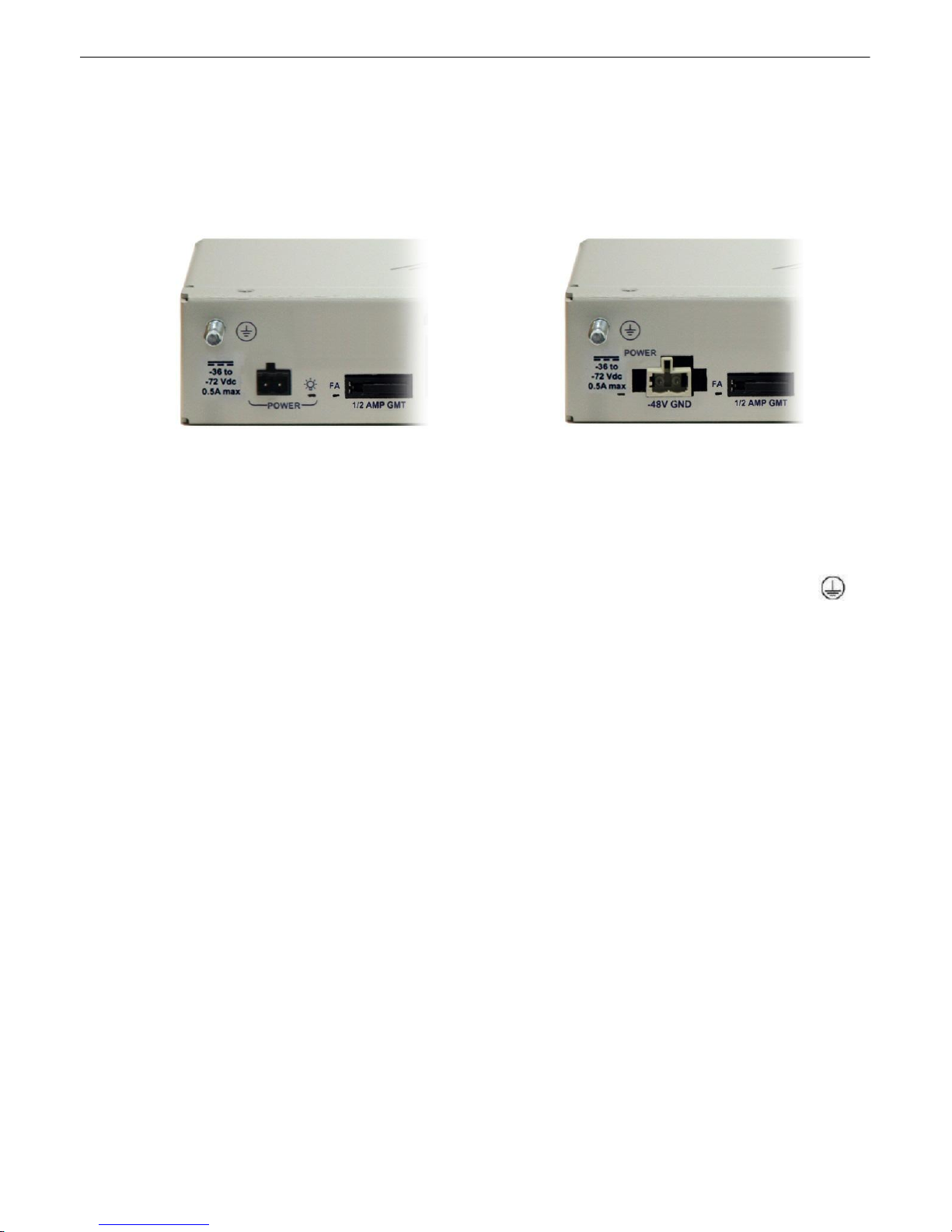
The VoIP Bridge Server can also be built with a single screw terminal barrier plug or WAGO power
connector.
Back panel power options
To connect the VoIP Bridge Server to a power supply, follow these steps:
1. Always use safe power practices when making power connections. Be sure to remove fuses from
the fuse distribution panel, as well as the back of the VoIP Bridge Server, before making your power
connections.
2. Use the grounding lug to connect the unit to earth ground. The grounding lug is next to the symbol
. Insert the eyelet of the earth ground cable between the two bolts on the grounding lug (Ground cable
not included).
3. Insert a battery ground into the power connector plug's right terminal and tighten the screw; then
insert a battery line to the plug's left terminal and tighten its screw.
4. Insert a fuse into the fuse distribution panel and measure voltage. The voltmeter should read between
–40 and –70VDC (for -48VDC build option) or -18 and -36VDC (-24VDC build option).
5. The power plug can be inserted into the power connector only one way to ensure the correct polarity.
Note that the negative voltage terminal is on the left and the GND terminal is on the right.
6. Insert fuse into the fuse slot. The power LED should be lit green. To confirm that power is correctly
connected, the front panel LEDs will flash RED and GREEN, indicating that the firmware is booting
up.
LAN Connection5.3
To connect the VoIP Bridge Server to the LAN, insert a standard RJ45 Ethernet cable into the
10/100BaseT Ethernet port on the back of the unit. If the LAN connection is OK, the LNK LED will light
SOLID GREEN.
Page 15
11
6
VoIP Bridge Server Front Panel
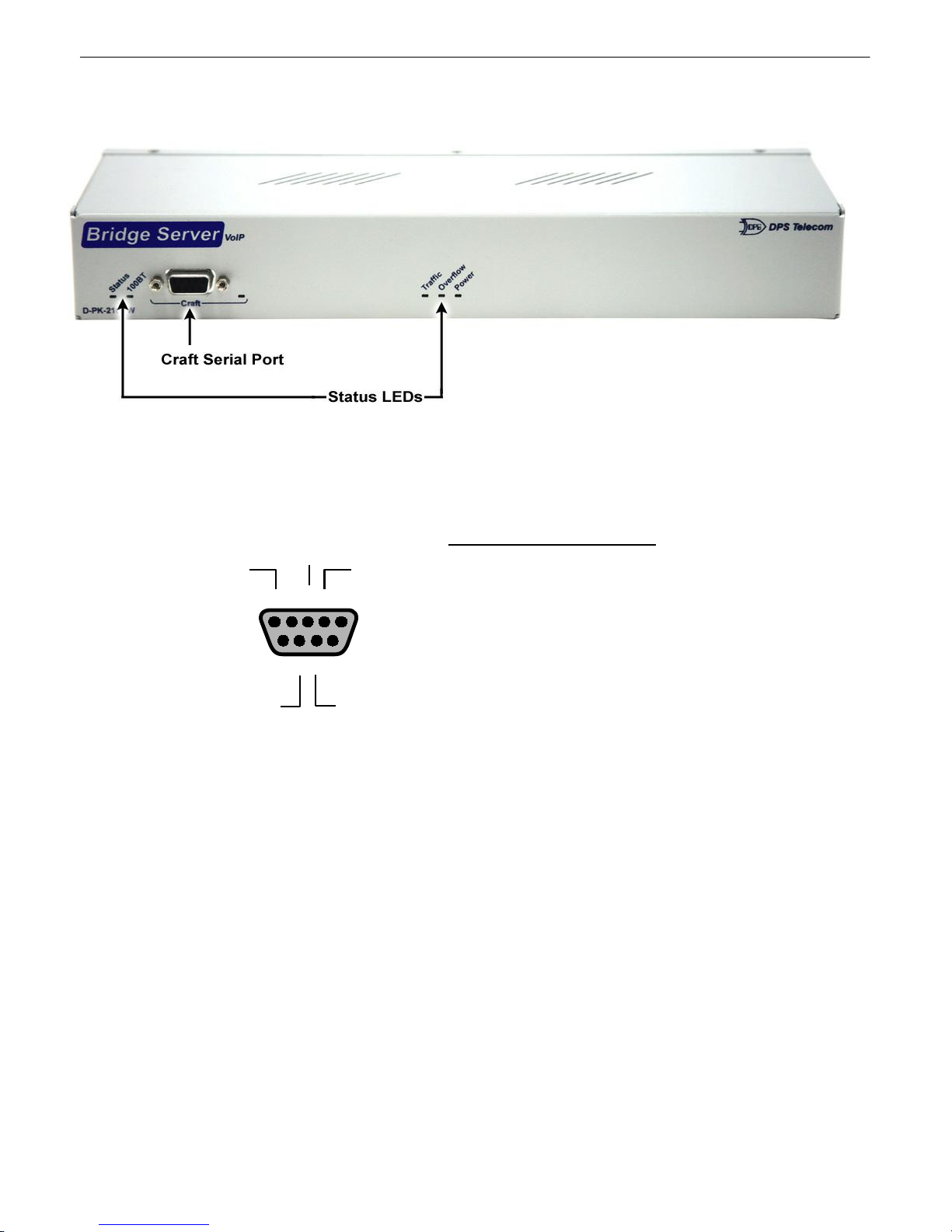
VoIP Bridge Server Front panel connections and LEDs
Craft Port6.1
DB9 RS-232
GND
RTS
RX
TX
12345
6789
CTS
Pin # Signal Description
1 Not connected
2 TX Transmit data
3
4
5 GND Ground
6 Not connected
7
8
9 Not connected
RX
CTS Clear to send
RTS
Recieve Data
Not connected
Request to send
VoIP Bridge Server Front panel connections and LEDs
Use the front panel craft port to connect the VoIP Bridge Server to a PC for onsite unit configuration. To
use the craft port, connect the included DB9 download cable from your PC's COM port to the craft port.
This is a standard DB9 to DB9. A pinout is shown above for reference.
Page 16
12
LED
Status
Description
Status
Flashing Green
Application is running
Flashing Red
Boot Loader is running.
100BT
Solid Green
100 Mb/s
Off
10 Mb/s
Craft
Flashing Red
Receiving data via craft port
Flashing Green
Transmitting data via craft port
Traffic
Flashing Red
Receiving data via LAN
Flashing Green
Transmitting data via LAN
Overflow
Flashing Red
More traffic than Bridge Server can handle
Off
Traffic is within acceptable limits
Power
Solid Green
Power supply OK
Off
No voltage or leads reversed
LED
Status
Description
PWR
Solid Green
Power supply OK
Off
No voltage leads reversed
FA
Solid Red
Fuse failure ("FA" = "Fuse Alarm")
Off
Fuse functioning normally
LNK
Solid Green
Ethernet link detected
LAN
Flashing Green
Traffic activity over LAN
7
Front and Back Panel LEDs
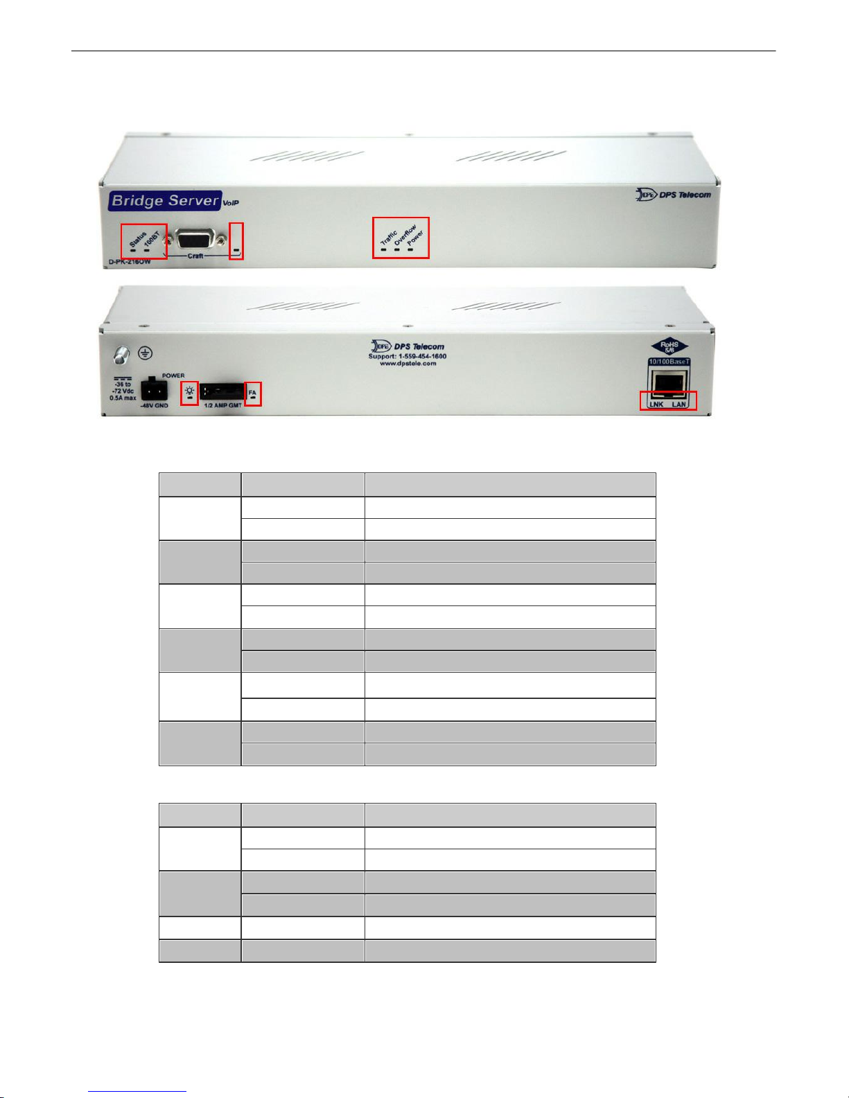
VoIP Bridge Server LEDs
Front Panel LED Descriptions
Back Panel LED Descriptions
Back Panel LED Descriptions
Page 17
13
Before you may use the VoIP Bridge Server to make conference calls with other VoIP Order Wire
stations, you must first assign it an IP address, a subnet mask, and a default gateway. This
provisioning step is performed within the TTY interface.
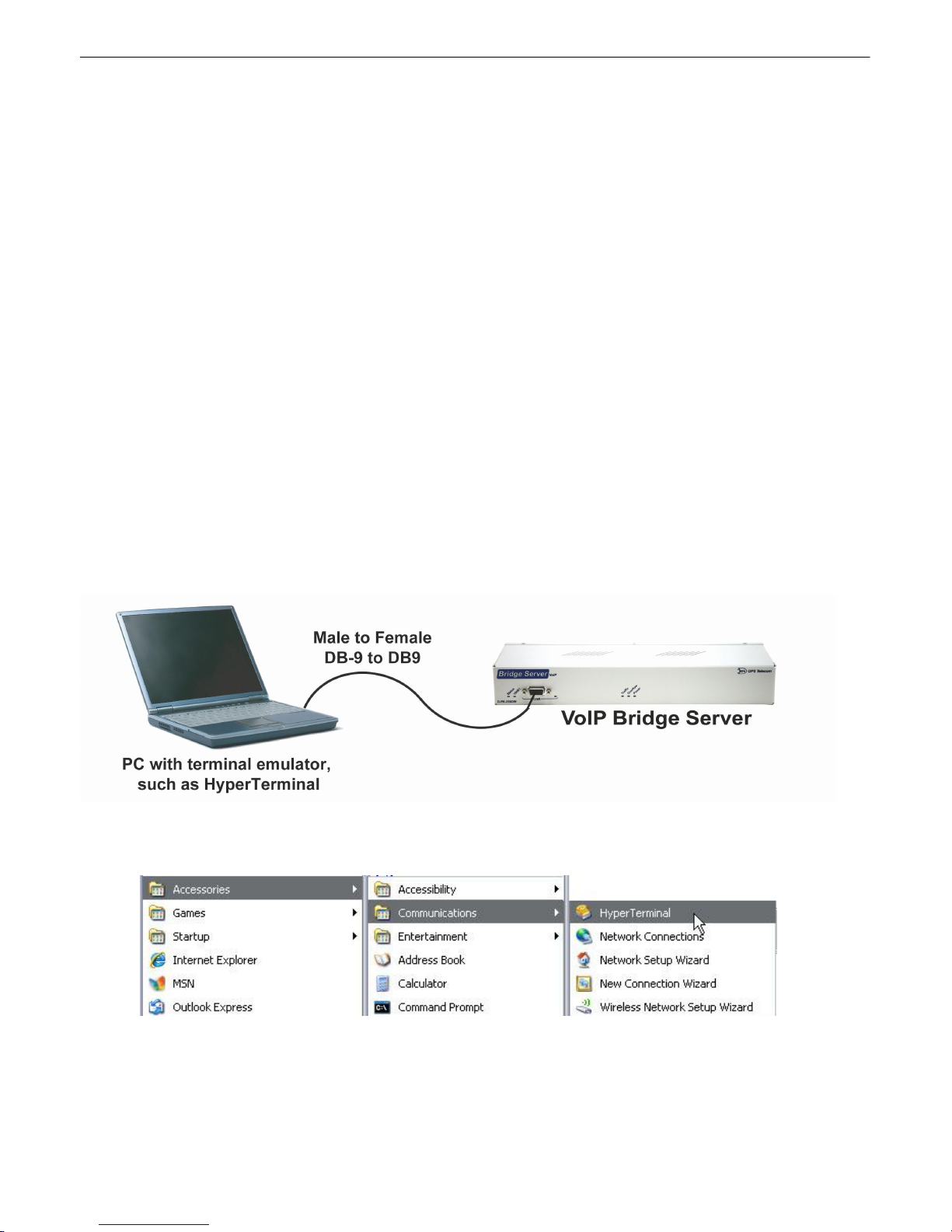
1. To connect to the VoIP Bridge Server for IP address provisioning, use a physical cable connection
between your PC's COM port and the unit's craft port. Note: You must be connected via craft port
or Telnet to use the TTY interface. Make sure you are using the straight through (1 to 1) Male to
Female DB9-DB9 download cable provided with your VoIP Bridge Server to make a craft port
connection. We'll be using HyperTerminal to connect to the unit in the following example however, most terminal-emulating programs should work.
To access HyperTerminal using Windows:
2. Click on the Start menu > select Programs > Accessories > Communications >
HyperTerminal.
8
The following steps are required in order to setup the VoIP Bridge Server and make your first conference call:
1. Set the VoIP Bridge Server's IP Address (using the TTY interface).
2. Add the VoIP Bridge Server to your VoIP Order Wire configuration using the "Orderwire Config"
3. Follow the voice menu prompts on 1 or more VoIP Order Wire stations to connect to the VoIP Bridge
How to Set Up the VoIP Bridge Server
software.
Server and begin a conference call.
Set Bridge Server IP via Craft Port (using TTY Interface)8.1
Page 18
14
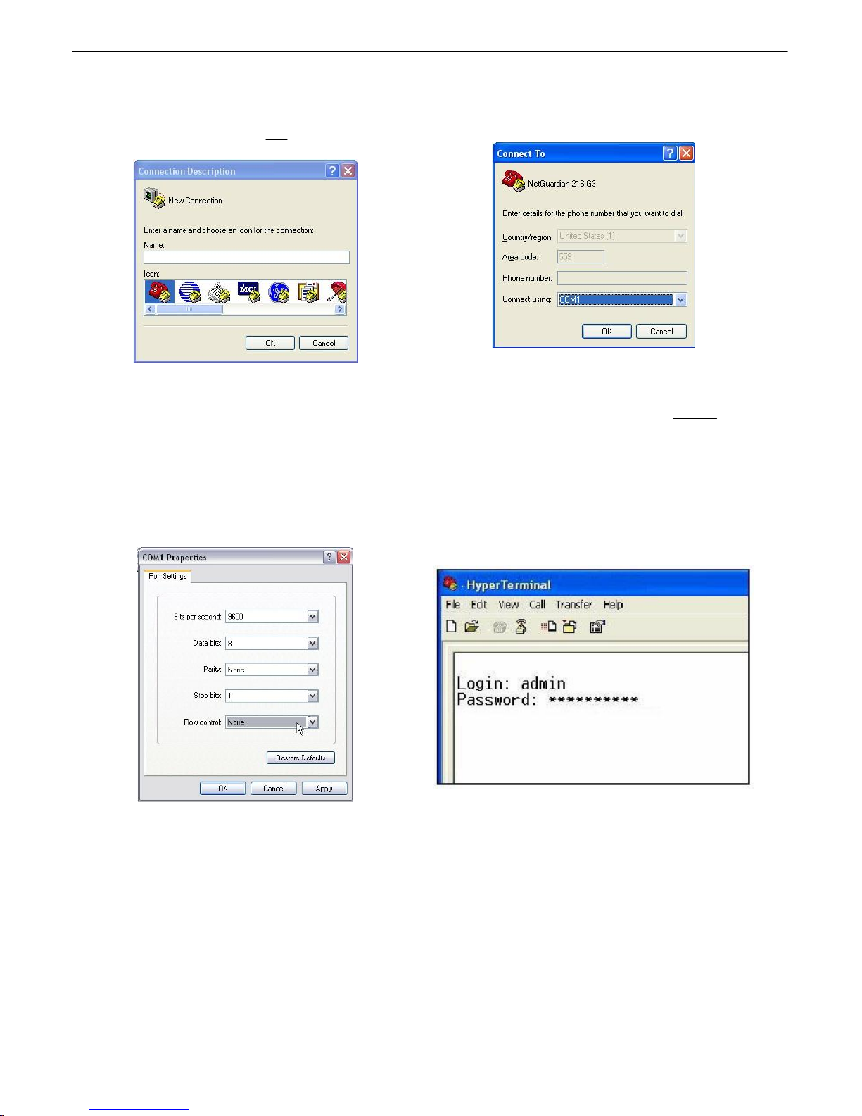
3. At the Connection Description screen, enter a
name for this connection. You may also select an
icon. The name and icon do not affect your ability
to connect to the unit.
4. At the Connect To screen, select Com port
you'll be using from the drop down and click OK.
(COM1 is the most commonly used.)
5. Select the following COM port options:
• Bits per second: 9600
• Data bits: 8
• Parity: None
• Stop bits: 1
• Flow control: None
Once connected, you will see a blank, white
HyperTerminal screen. Press Enter to activate
the configuration menu.
6. When prompted, enter the default user name
admin and password dpstelecom. NOTE: If
you don't receive a prompt for your user name
and password, check the Com port you are
using on your PC and make sure you are using
the cable provided.
Additional cables can be ordered from DPS
Telecom: Part number D-PR-045-10A-04
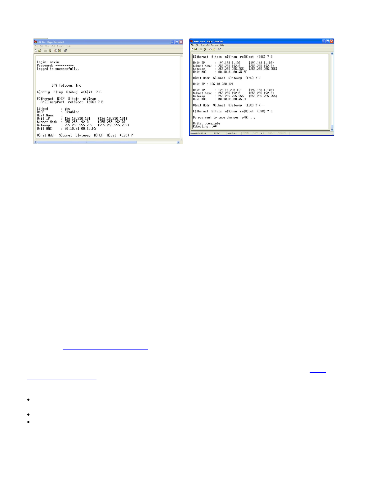
7. The VoIP Bridge Server's main main menu will
appear. Type C for C)onfig, then E for E)thernet.
Configure the unit's IP address, subnet mask, and
default gateway.
8. ESC to the main menu. When asked if you'd
like to save your changes, type Y for Y)es.
Reboot the VoIP Bridge Server to save its new
configuration.
Page 19
You have successfully assigned an IP address to the VoIP Bridge Server. This is the only
configuration step required within the VoIP Bridge Serverself. Next, you will need to provision
your VoIP Order Wire devices with the IP address of this VoIP Bridge Server.
NOTE: If you changed your computer's IP earlier in order to connect to the VoIP Bridge Server, be sure
to change the IP of your computer back to one that operates on your network.
15
Add the Bridge Server to your Order Wire Configuration8.2
To simplify the process of dialing into a conference call, VoIP Bridge Servers must be pre-databased in the
configuration of any VoIP Order Wire station that will connect to that VoIP Bridge Server (in most cases, all stations
will be updated). This process allows fast 2-digit dialing to reach a Bridge Server, rather than the cumbersome
process of dialing a full IP address with a phone keypad.
NOTE: These instructions describe only the configuration of the "Conference Servers" tab. The other tabs,
especially "Directory", must also be configured as part of a new VoIP deployment. If no Order Wire stations have
been listed in the "Directory" tab, the "Write to all devices" step at the end of this section will have no effect. Refer
to the Help file contained within Orderwire Config for information about configuring the other software tabs.
1. To add Bridge Servers into your Order Wire station configuration, launch the "Orderwire Config" application
that was packaged with your VoIP Order Wire stations. If you do not have this software, it is available as a free
download at: http://www.dpstele.com/mydps/
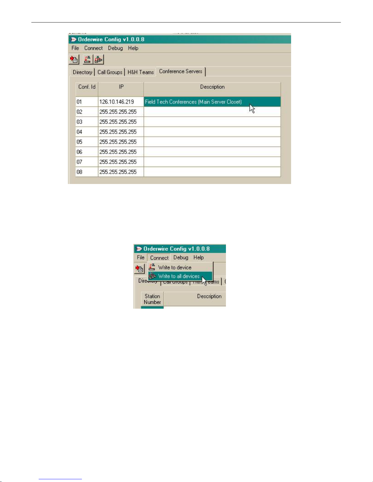
2. Next, you must add a new entry in the "Conference Servers" tab for your new VoIP Bridge Server. If your
version of the Orderwire Config software does not have this tab, you should download the latest version at http://
www.dpstele.com/mydps/
As shown in the example below, enter the following information for your VoIP Bridge Server:
A two-digit "Conf. Id" number (01-08). This number will be dialed from a VoIP Order Wire station to reach the
Bridge Server.
The "IP" address of the Bridge Server that you defined earlier.
A "Description" that will serve as a helpful reminder for you. In the example below, the Description field has
been used to store the purpose and location of the Bridge Server.
Page 20
16
If you have additional Bridge Servers, you may use the other rows to configure them as well. Up to 8 Bridge Servers
may be defined in a single Order Wire configuration.
3. Once you are satisfied with your configuration update, you must write the configuration to your VoIP Order
Wire stations for it to take effect. The simplest method is to click "Connect" >> "Write to all devices". This will write
the configuration to all devices defined in the "Directory" tab of Orderwire Config.
Your Bridge Server configuration has now been saved to your Order Wire stations (as listed in the
"Directory" tab). You are now ready to make your first conference call, as described in the next section.
Page 21

Dial into the Bridge Server from Order Wire stations8.3
After giving your Bridge Server an IP address and adding it to the configuration of your Order Wire stations,
you're now ready to make your first conference call using the Bridge Server.
1. Pick up the handset of a VoIP Order Wire station.
2. Dial '3' to "join a conference." (Pressing '#' instead will list the various menu options, including "To join a
conference, press '3'". Experienced conference users, however, will simply press '3' directly after picking up the
handset). After dialing '3', you will be prompted to "Enter 2-digit conference ID."
3. Dial the 2-digit "Conf. Id" (01-08) of your desired Bridge Server. You defined this in the Order Wire
configuration during the previous setup section.
You will now be connected to the conference, but you will be the only person on the call. If you wish, you
may dial into the call from another Order Wire station (use the same 3 steps above) to test the conference call
functionality.
Users on a conference call will hear an automatic verbal announcement when a user enters or leaves the
conference call. The joining user will also hear the verbal announcement of his/her own entry into the room.
NOTE: A single VoIP Bridge Server will support up to 5 simultaneous users. Any user who attempts to join
a conference call that is already full will hear an error prompt.
17
Page 22

18
9
The VoIP Bridge Server's web interface is used for only one purpose: upgrading firmware. To
connect, type the VoIP Bridge Server's assigned IP address into the address bar of your web browser
followed by /multiload (http://yourIPaddress/multiload), and press Enter.
At the login prompt, use the following username and password (NOTE: The username and password
cannot be modified):
Username: admin
Password: dpstelecom
Once logged in, you have the option to browse for a firmware file (*.mpb) and write it to the VoIP Bridge
Server.
How to Upgrade Firmware Via LAN
Page 23

19
10
Here are answers to some common questions from VoIP Bridge Server users. The latest FAQs can be
found on the DPS Telecom support web page, http://www.dpstele.com/support/
If you have a question about the VoIP Bridge Server, please call DPS Telecom at (559) 454-1600 or e-
mail us at [email protected]
Frequently Asked Questions
General FAQs10.1
Q. How do I telnet to the VoIP Bridge Server?
A. You must use Port 2002 to connect to the VoIP Bridge Server. Configure your Telnet client to
connect using TCP/IP (not "Telnet," or any other port options). For connection information, enter the
IP address of the VoIP Bridge Server and Port 2002. For example, to connect to the VoIP Bridge
Server using the standard Windows Telnet client, click Start, click Run, and type "telnet <VoIP
Bridge Server IP address> 2002."
Q. How do I connect my VoIP Bridge Server to the LAN?
A. Remember that the only purpose of the VoIP Bridge Server's web interface is to update firmware.
To connect your VoIP Bridge Server to your LAN, you need to configure the unit IP address, the
subnet mask, and the default gateway via the TTY interface (using Telnet). A sample configuration
could look like this:
Unit Address: 192.168.1.100
subnet mask: 255.255.255.0
Default Gateway: 192.168.1.1
Save your changes by writing to NVRAM and reboot. Any change to the unit's IP configuration
requires a reboot.
Q. When I connect to the VoIP Bridge Server through the craft port on the front panel it either
doesn't work right or it doesn't work at all. What's going on?
A. Make sure your using the right COM port settings. Your COM port settings should read:
Bits per second: 9600 (9600 baud)
Data bits: 8
Parity: None
Stop bits: 1
Flow control: None
Important! Flow control must be set to none. Flow control normally defaults to hardware in most
terminal programs, and this will not work correctly with the VoIP Bridge Server.
Q. I'm unsure if the voltage of my power supply is within the specified range. How to I test the
voltage?
A. Connect the black common lead of a voltmeter to the ground terminal of the battery. Connect the
red lead of the voltmeter to the battery's VDC terminal. The voltmeter should read a value that is
within the range listed in the "Specifications" section of this manual. The acceptable voltage range is
also commonly listed on the back panel of the unit near the power connector.
Page 24

20
11
DPS Telecom products are backed by our courteous, friendly Technical Support representatives, who
will give you the best in fast and accurate customer service. To help us help you better, please take the
following steps before calling Technical Support:
1. Check the DPS Telecom website.
Technical Support
You will find answers to many common questions on the DPS Telecom website, at http://www.
dpstele.com/support/. Look here first for a fast solution to your problem.
2. Prepare relevant information.
Having important information about your DPS Telecom product in hand when you call will greatly
reduce the time it takes to answer your questions. If you do not have all of the information when you
call, our Technical Support representatives can assist you in gathering it. Please write the information
down for easy access. Please have your user manual and hardware serial number ready.
3. Have access to troubled equipment.
Please be at or near your equipment when you call DPS Telecom Technical Support. This will help us
solve your problem more efficiently.
4. Call during Customer Support hours.
Customer support hours are Monday through Friday, from 7 A.M. to 6 P.M., Pacific time. The DPS
Telecom Technical Support phone number is (559) 454-1600.
Emergency Assistance: Emergency assistance is available 24 hours a day, 7 days a week. For
emergency assistance after hours, allow the phone to ring until it is answered with a paging message.
You will be asked to enter your phone number. An on-call technical support representative will return
your call as soon as possible.
Page 25

21
12
All Software and firmware used in, for, or in connection with the Product, parts, subsystems, or derivatives thereof,
in whatever form, including, without limitation, source code, object code and microcode, including any computer
programs and any documentation relating to or describing such Software is furnished to the End User only under a
non-exclusive perpetual license solely for End User's use with the Product.
The Software may not be copied or modified, in whole or in part, for any purpose whatsoever. The Software may not
be reverse engineered, compiled, or disassembled. No title to or ownership of the Software or any of its parts is
transferred to the End User. Title to all patents, copyrights, trade secrets, and any other applicable rights shall
remain with the DPS Telecom.
DPS Telecom's warranty and limitation on its liability for the Software is as described in the warranty information
provided to End User in the Product Manual.
End User shall indemnify DPS Telecom and hold it harmless for and against any and all claims, damages, losses,
costs, expenses, obligations, liabilities, fees and costs and all amounts paid in settlement of any claim, action or
suit which may be asserted against DPS Telecom which arise out of or are related to the non-fulfillment of any
covenant or obligation of End User in connection with this Agreement.
This Agreement shall be construed and enforced in accordance with the laws of the State of California, without
regard to choice of law principles and excluding the provisions of the UN Convention on Contracts for the
International Sale of Goods. Any dispute arising out of the Agreement shall be commenced and maintained only in
Fresno County, California. In the event suit is brought or an attorney is retained by any party to this Agreement to
seek interpretation or construction of any term or provision of this Agreement, to enforce the terms of this
Agreement, to collect any money due, or to obtain any money damages or equitable relief for breach, the prevailing
party shall be entitled to recover, in addition to any other available remedy, reimbursement for reasonable attorneys'
fees, court costs, costs of investigation, and other related expenses.
End User License Agreement
Page 26

Page 27

Warranty
DPS Telecom warrants, to the original purchaser only, that its products a) substantially conform to DPS' published
specifications and b) are substantially free from defects in material and workmanship. This warranty expires two
years from the date of product delivery with respect to hardware and ninety days from the date of product delivery
with respect to software. If the purchaser discovers within these periods a failure of the product to substantially
conform to the specifications or that the product is not substantially free from defects in material and workmanship,
the purchaser must promply notify DPS. Within reasonable time after notification, DPS will endeavor to correct any
substantial non-conformance with the specifications or substantial defects in material and workmanship, with new or
used replacement parts. All warranty service will be performed at the company's office in Fresno, California, at no
charge to the purchaser, other than the cost of shipping to and from DPS, which shall be the responsiblity of the
purchaser. If DPS is unable to repair the product to conform to the warranty, DPS will provide at its option one of the
following: a replacement product or a refund of the purchase price for the non-conforming product. These remedies
are the purchaser's only remedies for breach of warranty. Prior to initial use the purchaser shall have determined the
suitability of the product for its intended use. DPS does not warrant a) any product, components or parts not
manufactured by DPS, b) defects caused by the purchaser's failure to provide a suitable installation environment for
the product, c) damage caused by use of the product for purposes other than those for which it was designed, d)
damage caused by disasters such as fire, flood, wind or lightning unless and to the extent that the product
specification provides for resistance to a defined disaster, e) damage caused by unauthorized attachments or
modifications, f) damage during shipment from the purchaser to DPS, or g) any abuse or misuse by the purchaser.
THE FOREGOING WARRANTIES ARE IN LIEU OF ALL OTHER WARRANTIES, EXPRESS OR IMPLIED,
INCLUDING BUT NOT LIMITED TO THE IMPLIED WARRANTIES OF MERCHANTABILITY AND FITNESS FOR A
PARTICULAR PURPOSE.
In no event will DPS be liable for any special, incidental, or consequential damages based on breach of warranty,
breach of contract, negligence, strict tort, or any other legal theory. Damages that DPS will not be responsible for
include but are not limited to, loss of profits; loss of savings or revenue; loss of use of the product or any associated
equipment; cost of capital; cost of any substitute equipment, facilities or services; downtime; claims of third parties
including customers; and injury to property.
The purchaser shall fill out the requested information on the Product Warranty Card and mail the card to DPS. This
card provides information that helps DPS make product improvements and develop new products.
For an additional fee DPS may, at its option, make available by written agreement only an extended warranty
providing an additional period of time for the applicability of the standard warranty.
Page 28
Free Tech Support is Only a Click Away
Need help with your alarm monitoring? DPS Information Services are ready to
serve you … in your email or over the Web!
www.DpsTele.com
Free Tech Support in Your Email: The Protocol Alarm Monitoring Ezine
The Protocol Alarm Monitoring Ezine is your free email
tech support alert, delivered directly to your in-box
every two weeks. Every issue has news you can use
right away:
•
Expert tips on using your alarm monitoring
equipment - advanced techniques that will save
you hours of work
•
Educational White Papers deliver fast informal
tutorials on SNMP, ASCII processing, TL1 and
other alarm monitoring technologies
•
New product and upgrade announcements keep
you up to date with the latest technology
•
Exclusive access to special offers for DPS
Telecom Factory Training, product upgrade offers
and discounts
To get your free subscription to
The Protocol register online at
www.TheProtocol.com/register
Free Tech Support on the Web: MyDPS
MyDPS is your personalized, members-only online resource.
Registering for MyDPS is fast, free, and gives you exclusive
access to:
• Firmware and software downloads and upgrades
• Product manuals
• Product datasheets
• Exclusive user forms
Register for MyDPS online at
www.DpsTele.com/register
(800) 622-3314 • www.DpsTele.com • 4955 E. Yale Avenue, Fresno, California 93727
 Loading...