

Page 1
DPS Telecom
User Manual
Terminal Package*
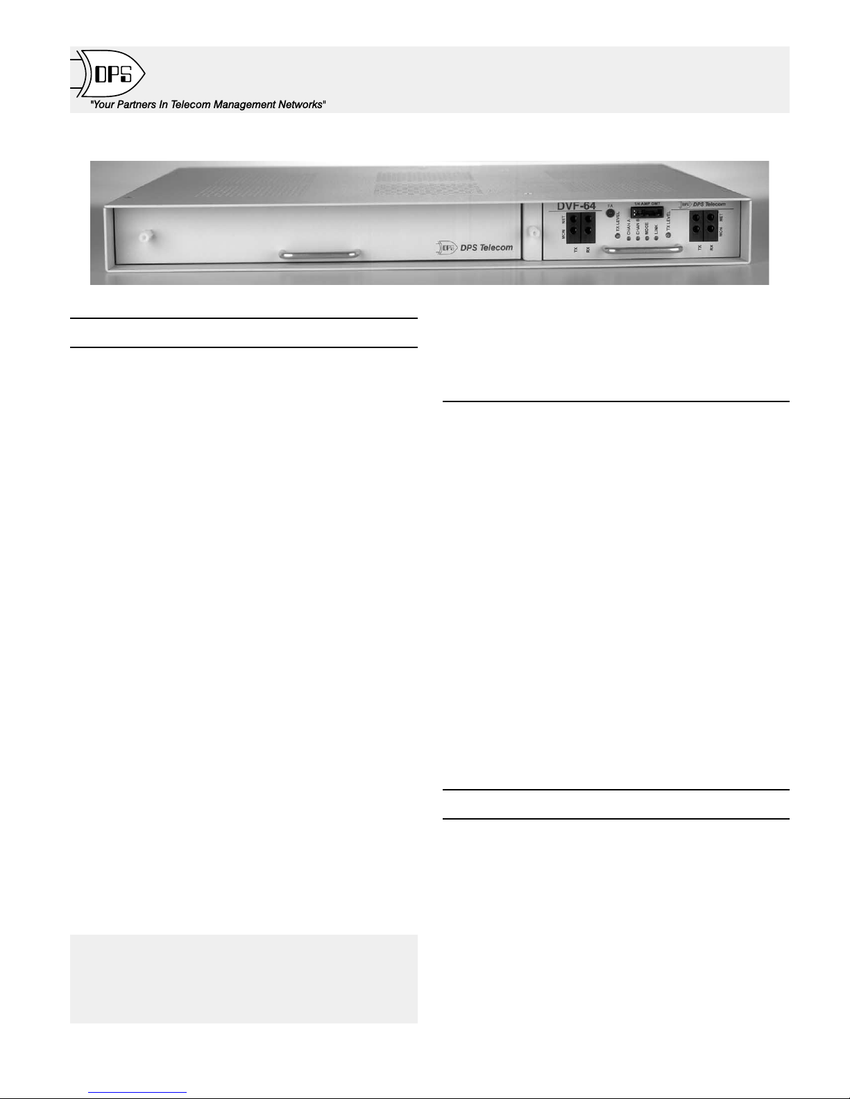
Fig. 1 - Digital Base Terminal Package consists of blank card and DVF-64 digital interface card.
Description
The Digital Base Terminal package (DPS Part Number
D-PG-413-11C-00) provides interface for RS422 data, 202
modem data and digital order-wire voice to a 64 KBit SONET
ring.
The package consists of a DVF-64 Digital Interface Card and
a blank place-holder card (for future addition af a DPS KDA
864 network element or FDO 3000 Order-Wire Off-Net card)
in a 1-3/4” rack-mount housing. The housing includes a
connectorized and wire-wrap back plane that is fully wired to
accept a KDA 864-TABS, KDA 864-E2A or FDO 3000
Off-Net plug-in module.
DVF-64 Card
DPS’ Digital-VF 64 KBit Converter (DVF-64) is an ideal solution for those network operators with an embedded analog
network who find themselves stepping up to a digital network
such as SONET. The DVF-64 provides an interface between an
analog voice frequency network or device and a 64 kilobit digi
tal overhead on a digital network.
Two separate VF circuits are included on the module, with a
switchable bridging network that allows the two circuits to per
form in a either a terminal or a repeater application. Signals at
the VF ports are converted to a 32 Kbit channel.
The DVF-64 provides a 24 Kbit port for digital order-wire to
interface via an Adaptive PCM card in a companion order-wire
shelf. It also provides a dual 8 Kbit port for RS 422 data.
The DVF-64 assembles the three digital channels into one 64
Kbit data stream.
The DVF-64 is available as an expansion card that fits into
the expansion card slot on a DPS KDA network element.
DVF-64 Connectors
The back panel includes connectors for interfacing the
ADPCM card in an optional companion order-wire shelf. Con
Change Notice
8/11/99: Added center-fold, model chart and glossary.
nectors are also provided for interfacing A and B sections on
the 64 Kbit channel. Access to the other DVF-64 ports is pro
vided at the wire-wrap block.
Companion packages
Companion packages are available to use with the Digital
Base Terminal Package to add order-wire and Adaptive PCM
functions. These packages plug into the connectors on the back
of the Digital Base Terminal Package, making the addition of
these functions easy.
An Order-Wire expansion package adds voice interface at a
site that has only the Digital Base Terminal Package. This order-wire package includes an Adaptive PCM card to digitize
the voice and interface it to the 24 KBit channel of the DVF-64.
The order-wire card includes a passive four-way bridge, which
can be used to interface other voice signals.
Another expansion package is available which adds an
Adaptive PCM card in an order-wire chassis. This package is
useful for interfacing non-DPS order-wire networks to the
SONET network. It allows an existing order-wire or network to
transport via the 24 KBit channel of the DVF-64 card.
-
Plug-in cards are available to add a KDA 864 network ele
ment or FDO 3000 Off-Net to the Digital Base Terminal Pack
age.
NOTE: The Terminal Package must be joined to an FDO
1000 Order-Wire package for the off-net to work.
Table of Contents
Description .................................1
Applications ................................2
Installation .................................4
LED Display ................................9
-
Specifications ..............................11
Options and Model Numbers .................11
*See Table D on page 8 for a listing of packages that use the
Terminal package.
-
-
-
D-PG-413-11C-00 1 UM118129
August 11, 1999
Page 2
from ADPCM (in Order-wire shelf)
Digital voice
24 Kbit
A
RS422 (8 Kbit)
B
Section A
DVF-64
64 Kbit (to SONET)
RS 422 application with a TABS network element
A
KDA 864-TABS
RS422 (8 Kbit)
B
Section A
202 modem application with an E2A network element
Digital voice from ADPCM
(in Order-wire shelf, if used)
A
VF (32 Kbit)
B
Section B
Digital voice from ADPCM
(in Order-wire shelf, if used)
24 Kbit
DVF-64
64 Kbit (to SONET)
A
VF
B
Section B
VF ports are
available to
transport 202
modem data
24 Kbit
A
RS422 (8 Kbit)
B
Section A
DVF-64
64 Kbit (to SONET)
A
VF (32 KBit)
B
(Unused)
Section B
RS 422 application with an NTP at a terminal location
from ADPCM (in Order-wire shelf, if used)
NTP
A end location
NTP
RS422 (8 Kbit)
B end location
Section A
KDA 864-E2A
A
B
64 Kbit (to SONET)
Digital voice
24 Kbit
DVF-64
A
VF
B
Section B
VF ports are
available to
transport 202
modem data
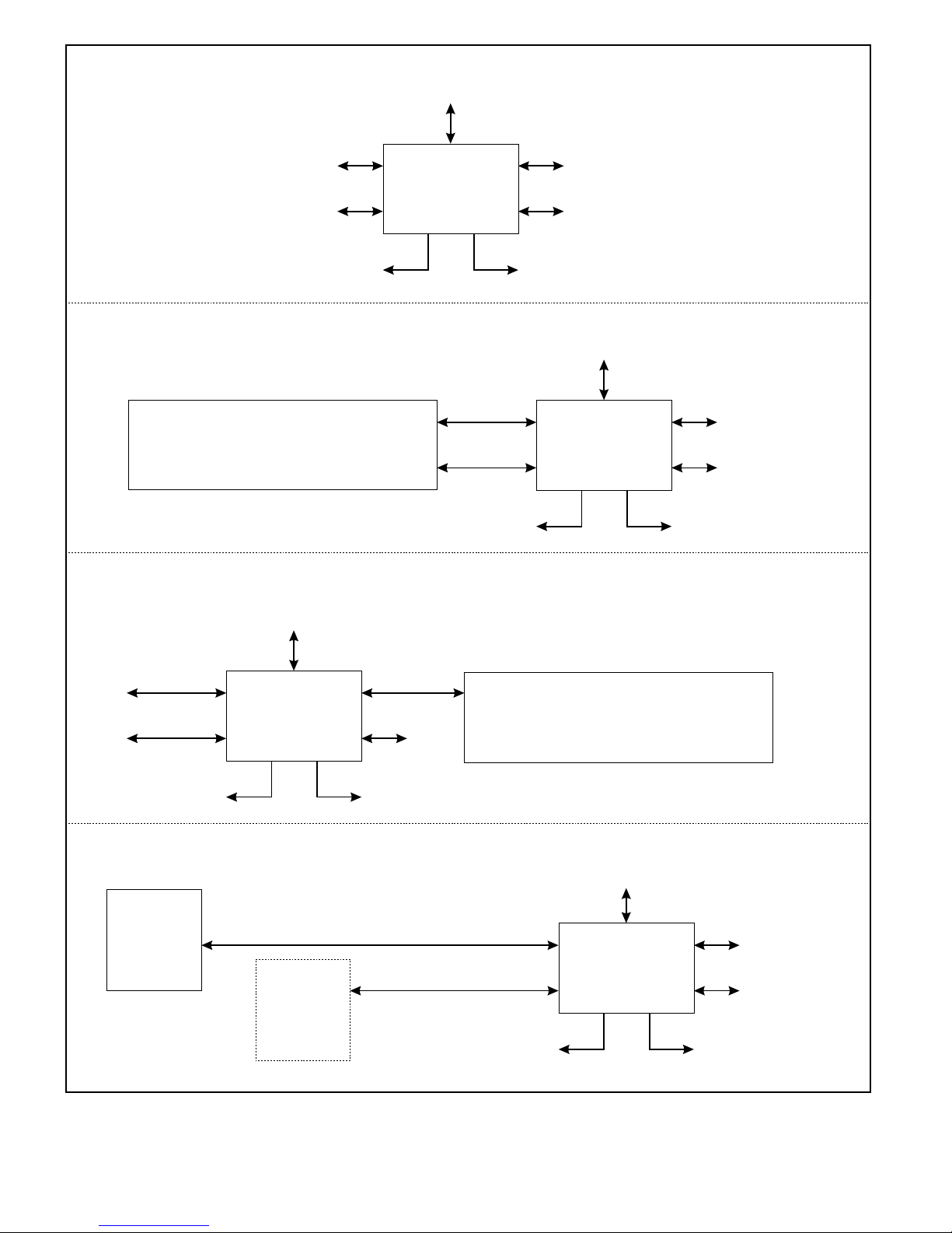
Fig. 2 - Digital Base Terminal Package interfaces 64 KBit overhead to order-wire voice, RS 422 data
UM118129 2 D-PG-423-11C-04
and 202 modem data.
August 11, 1999
Page 3
Applications
Shipping List
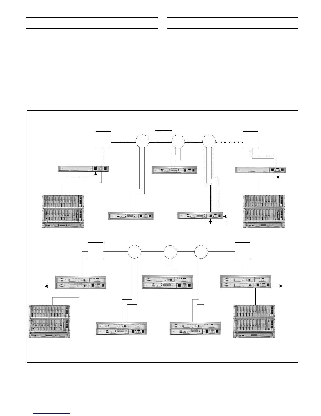
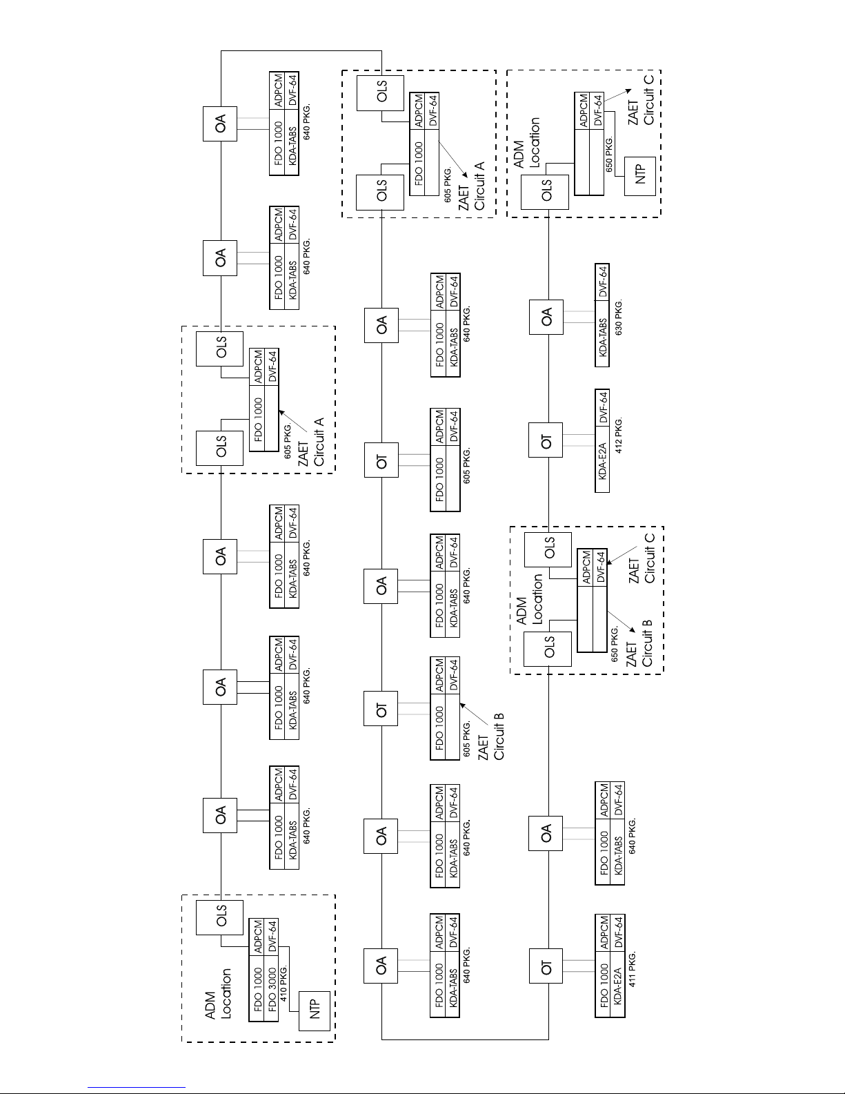
Fig. 2 shows the various applications of the Digital Base Ter
minal Package. A network illustration in Fig. 3 shows how the
Digital Base Terminal Package interfaces a TABS alarm
network to a SONET transport system. The VF ports can also
be used to "piggy-back" 202 modem data between sites in the
same network. It also shows how an order-wire can be inte
grated into the same network using other DPS packages.
VF Path
OW Chan.
32 Kbit VF channel
canalsobeusedto
carry VF modem data
Terminal
Aux. VF
Chan. A
Front
A-Chan.
Door
OW Chan.
OLS
OLS
or OT
or OT
RS422 TABS
(1200 Baud)
DVF-64
Satellite TABS
ABB
OA
OA
Satellite TABS
KDA 864-TABS
eq/w DVF-64 Expansion Card
-
-
Shelf
¤
Mounting hardware
¤
Fuses
¤
User Manual
¤
DVF-64 Card
¤
Interconnecting cables
¤
OA
A
AB
Satellite TABS
OLS
OW Chan.
OW Chan.
OLS
or OT
or OT
Terminal
DVF-64
OA
Back
Door
RS422 TABS
(1200 Baud)
A
B
Aux. VF
Chan. B
B-Chan.
KDA 864-TABS
eq/w DVF-64
OA
AAAB
AAAB
Satellite TABS
w/Order-Wire
FDO 1000 Order-Wire
KDA 864-TABS eq/w
DVF-64 Expansion Card
Aux. VF
Chan. A
OA
BB
BB
Aux. VF
Chan. B
OW Chan.
OLS
OLS
or OT
or OT
B-Chan.
RS422 TABS
(1200 Baud)
NTPNTP
NTP
Terminal
FDO 1000 Order-Wire
FDO 3000 Off-Net eq/w
DVF-64 Expansion Card
Off-net
Phone
Line
Back
Door
NTP
NTP
Terminal
FDO 1000 Order-Wire
FDO 3000 Off-Net eq/w
DVF-64 Expansion Card
Off-net
Phone
Line
Front
A-Chan.
Door
NTP
NTP
OW Chan.
OW Chan.
RS422 TABS
(1200 Baud)
KDA 864-TABS
eq/w DVF-64 Expansion Card
OLS
OLS
or OT
or OT
TABS TABS TABS TABS
TABS TABS TABS TABS
Satellite TABS
w/Order-Wire
FDO 1000 Order-Wire
KDA 864-TABS eq/w
DVF-64 Expansion Card
KDA864-TABS / DVF-64
OA
OA
Satellite TABS
w/Order-Wire
FDO 1000 Order-Wire
KDA 864-TABS eq/w
DVF-64 Expansion Card
KDA864-TABS / DVF-64 with order-wire and offnet
Fig. 3 - KDA 864-TABS reports network element status to an element manager via a digital network. DVF-64 VF
ports can be used to "piggy-back" 202 modem tones between sites. Order-wire and off net interface can be added.
D-PG-413-11C-00 3 UM118129
August 11, 1999
Page 4
19" or 23" Rack/
5" Projection
19" or 23" Rack/
Flush Front
19" or 23" Rack/
5-1/2" Projection
19" or 23" Rack/
1/2" Projection
NOTE: Use wide ears for 23"
SIDE VIEW REAR
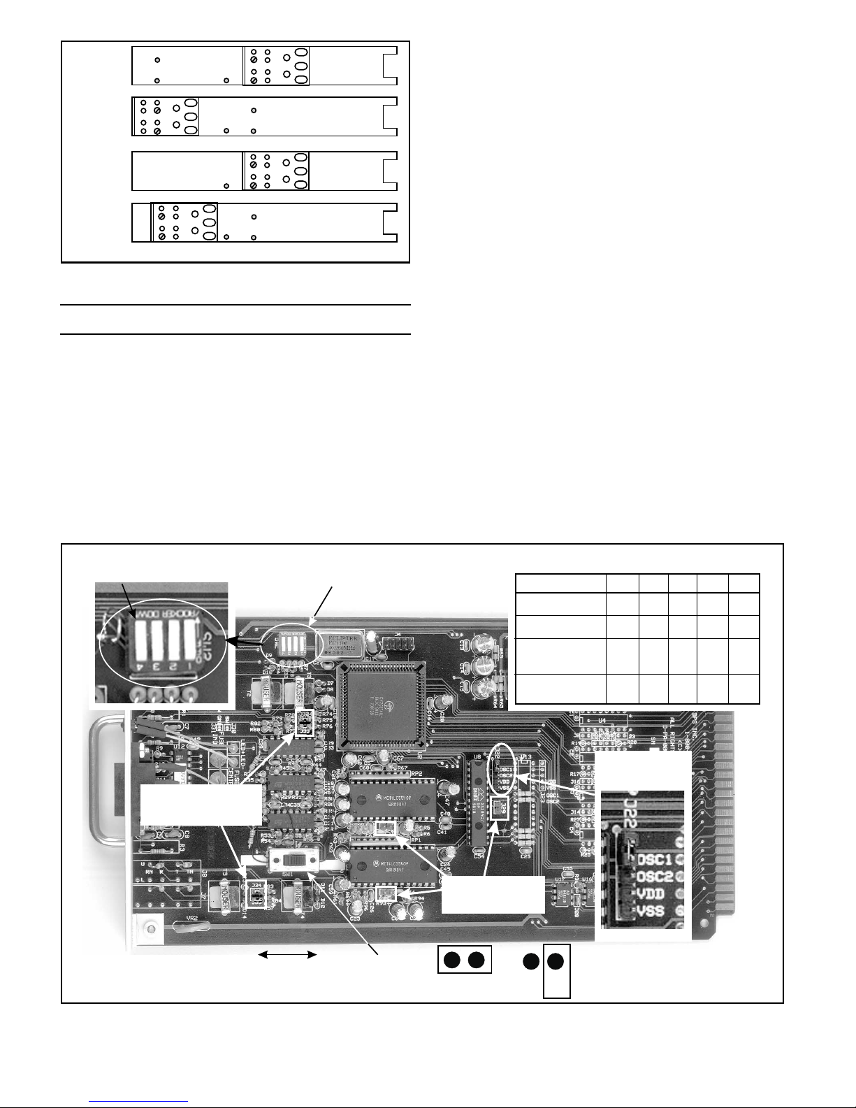
Fig. 4 - Position mounting ears for desired projection.
Installation
NOTE: The shelf fits in either a 19" or 23" rack. The mount
ing brackets on the side of the unit can be positioned for ei
ther 5" projection or flush mounting in a 19" rack or for
5-1/2" projection or 1/2" projection in a 23" rack.
1. Determine which mounting configuration is required and
orient the mounting brackets as shown in Fig. 4.
NOTE: Longer brackets are provided for 23” racks.
2. Attach each bracket with two 6-32 screws (provided in
hardware bag).
3. Place the shelf in the rack and align the mounting holes in
the brackets with the holes in the rack rails. Secure each
bracket with two 10-24 screws (provided in hardware bag).
NOTE: A wire-wrap tool with an .060" mandrel is required.
Refer to the wire wrap pin layout drawing (Fig. 8) for all
wire-wrap pin designations.
NOTE: The expansion card slot is factory wired for the
DVF-64 Digital Polling Channel.
4. Connect Fuse Alarm contacts to alarm device, if required.
(Refer to Fig. 8.)
5. Connect DB15 cables to the Network A and Network B
connectors on the back of the shelf.
6. Connect other end of cables to appropriate connector on
the fiber terminal. See Fig. 8 and Table B for DB15 pin-outs.
NOTE: Cable lengths are specified as 50’, 75’ or 100’ when
the shelf is ordered. If lengths are incorrect, contact DPS in
-
-
side sales to order the correct lengths.
7. Remove fuses from DVF-64 front panel.
-
8. Connect power at power barrier terminals. Refer to Fig. 8.
NOTE: Observe polarity of power connections. “Battery”
terminal is negative on -24 and -48 volt models.
NOTE: Do not replace fuses until board options are checked
and adjusted.
9. Remove DVF-64 p.c. board.
10. Set SW-1, Terminal/Repeater switch. Refer to Fig. 5.
(Continued on page 10)
Press switch down to turn off
1
2
34
J32 - J35
Default = Closed
Terminal Repeater
Sw 2
Sw 1
J23, J24, J29
Default = Open
J- Closed
Table C - DVF-64 Switch Settings
Application
End point, Section A
End point, Section B
Mid point (repeater),
E2A looping
Mid point,
E2A non-looping
SW1
Term.
Term.
Rptr.
Term.
SW2-1
ON
OFF
ON
ON
J22
Default=OSC1
J- Open
SW2-2
OFF
ON
ON
ON
SW2-3
OFF
OFF
ON
OFF
SW2-4
OFF
OFF
OFF
OFF
Fig. 5 - Set S2 and Terminal / Repeater switch on the DVF-64 card.
UM118129 4 D-PG-423-11C-04
August 11, 1999
Page 5
If You Have Add AddTo Make / If You Have To Make
414
Order-Wire
Off-Net
ADPCM
635
Order-Wire
ADPCM
413
413
+
DVF-64
DVF-64
+
413
650
660
413
413
635
Order-Wire
650
660
DVF-64
ADPCM
DVF-64
ADPCM
DVF-64
DVF-64
ADPCM
ADPCM
DVF-64
ADPCM
+
Order-Wire
+
Order-Wire
+
+
+
+
+
Order-Wire
+
Order-Wire
635
413
660
KDA E2A
413
ADPCM
DVF-64
ADPCM
DVF-64
605
Order-Wire
650
KDA E2A
605
Order-Wire
635
Order-Wire
412
ADPCM
DVF-64
ADPCM
DVF-64
DVF-64
ADPCM
DVF-64
ADPCM
+
+
+
+
+
Off-Net
Order-Wire
Off-Net
635
Order-Wire
KDA E2A
412
KDA E2A
ADPCM
DVF-64
410
Order-Wire
Off-Net
411
Order-Wire
KDA E2A
ADPCM
DVF-64
ADPCM
DVF-64
660
413
650
660
650
660
660
ADPCM
DVF-64
ADPCM
DVF-64
ADPCM
ADPCM
DVF-64
ADPCM
ADPCM
+
+
Order-Wire
+
Order-Wire
+
Order-Wire
+
KDA TABS
+
KDA TABS
+
413
635
630
413
DVF-64
ADPCM
DVF-64
DVF-64
650
605
Order-Wire
635
Order-Wire
645
KDA TABS
650
ADPCM
DVF-64
ADPCM
DVF-64
ADPCM
ADPCM
DVF-64
ADPCM
DVF-64
+
+
+
+
+
Order-Wire
KDA E2A
KDA TABS
KDA TABS
Order-Wire
Order-Wire
KDA TABS
630
DVF-64
640
Order-Wire
KDA TABS
ADPCM
DVF-64
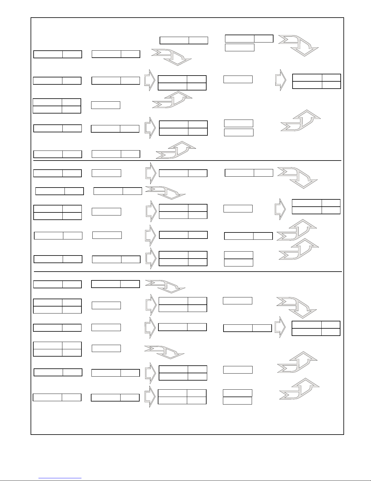
Fig. 6 - Packages can be expanded to make other packages.
D-PG-413-11C-00 5 UM118129
August 11, 1999
Page 6
6-7
Page 7

Glossary of Order-Wire and Alarm Remote Terms
ACO - Alarm cut off. Switch to silence an audible alarm.
When the ACO is “on,” the audible alarm device is silenced.
Alarm Point - A single discrete alarm input that requires a
discrete (usually on-to-off or off-to-on) change in current flow
or voltage to indicate a change of alarm condition from normal
to alarm state. Assigned to a point number in a display and ad
dress. Usually reported to master as a single bit in a data stream.
Battery - Facility DC power. Normally supplied from a bat
tery plant inside the office. Polarity is normally negative (posi
tive ground) in a telecom facility.
Baud - The data transmission rate that the Com Port uses to
talk to the equipment. Common data rates include: 1200, 2400,
4800, 9600, 19200 (19) and 38400 (38).
Change Of State - This is the condition of a point when it is
in transition from one state to another. Change of State is abbre
viated as COS.
Control Point - Relay isolated output that is controlled by
command from the master. Normally-open (SPST) dry contacts
are commonly used.
COS - This is the abbreviation for Change Of State.
Craft Port - Serial port for connection of a computer or
ASCII terminal to test and modify configuration of the remote.
Database - A file containing records of organized and related information.
Displays - Displays contain 64 points of data.
Download - The act of transferring a configuration file from
a computer to the KDA. Can be done remotely via the dial port
(modem), if equipped, or locally via the craft port.
DTMF - The abbreviation for Dual Tone Multi-Frequency.
This is a common touch tone telephone.
Expansion Card - Accessory card that fits into a slot at the
right side of the KDA chassis. Adds additional functions to the
host unit, such as the ADPCM and DVF-64 cards.
FDO - Model designation for DPS Telecom’s order-wire
product line. All products with this prefix are used with the or
der-wire.
KDA - Model designation for DPS Telecom’s alarm remote /
network element product line. All products with this prefix are
alarm remotes.
LED - The abbreviation for Light Emitting Diode. The LED
is used as an indicator of activity.
Modem - The abbreviation for Modulator/Demodulator.
Modems are used to transfer data over telephone lines.
Off-net - A connection point in the order-wire network for
the public switched telephone network (PSTN). Allows or
der-wire stations to have access for global communications.
Optically Isolated - Electrical interface, such as a discrete
alarm point input, that isolates the external circuitry from the
internal circuitry of the KDA with an optical coupler. Optical
Isolation reduces the possibility of electrical mis-match or in
terference between the KDA and the alarm sources.
Order-Wire - Voice communications device for mainte
nance personnel. Often includes data for alarms and network
management. Other terms are service channel and supervisory.
Polarity - The polarity of a point can be either Normal
(NRM) or Reverse (RVS). Normal polarity is current flow in a
closed circuit for an alarm.
-
POTS - Plain Old Telephone Service. A 2-wire phone line to
a central office switch.
-
-
RTU - Remote Telemetry Unit. An RTU is a device that
gathers alarm inputs and communicates them to a master alarm
station.
Satellite - Additional KDA units at the same location and
communicating with the master through a “base” KDA. Up to
three satellites can be associated with a base KDA. Using satel
lites expands the use of a remote address, allowing greater sys
tem capacity.
TBOS - Telemetry-Byte-Oriented-Serial protocol. A
well-established alarm system protocol used by many
telco-oriented manufacturers. Normally embedded in switches,
channel banks and other equipment with many alarm points.
TBOS normally uses an RS422 serial port. A port has a capac
ity of 512 alarm points, divided into 8 “displays” of 64 points
each.
Traffic - Activity on the line or channel.
Wire-Wrap - Wire connection points using a steel post that
the connecting wire is wrapped around using a special tool.
-
-
-
-
-
-
-
UM118129 8 D-PG-423-11C-04
August 11, 1999
Page 8
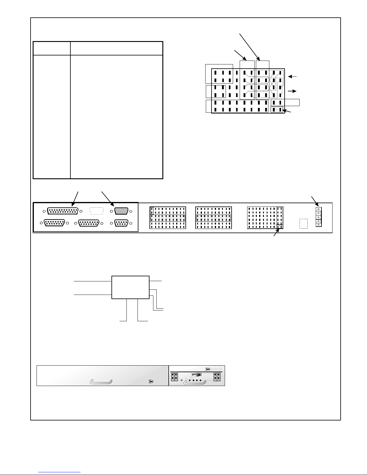
Table B - Network Connector Pinouts
(DB 15 - DTE)
Pin No.
1
2
3
4
5
6
7
8
9
10
11
12
13
14
15
Function
TCLK (-) (Clock input)
TSYN (-) (Sync input)
TXD (-) (DPS data output)
RXD (-) (DPS data input)
RSYN (-)
RCLK (-)
N/C
N/C
TCLK (+)
TSYN (+)
TXD (+) (DPS data output)
RXD (+) (DPS data input)
RSYN (+)
RCLK (+)
N/C
E2A/202 Modem
Connections
TABS RS422
Connections
Alarm
points
61-63
2W**
POTS line
Control
points
1-8
Jumpers are factory
installed for
KDA 864-TABS*
application.
B
A
AB
T
Wire-Wrap
R
Block C3
1
T
R
Shield
Details
1
Fuse alarm
12345678910
*To convert to KDA 864 E2A application,
remove jumpers and re-jumper
pin 7A to 9C, 7B to 9D,
7C to 9A and 7D to 9B.
**To convert to FDO 3000 Off-Net application,
remove jumpers and re-jumper pin 1C to 2C
and 1D to 2D.
These ports not used in this application
AD
PCM
12
DB15 Female
8
Section A
DB25 Female
1
915
Network
1
1325
DB15 Female
8
Section B
DB9 Male
1
5
VF
6
DB9 Female
1
5
915
9
Data
ALM
RTN
9
1
ALM
6
RTN
Back View
C1
12345678910
21 22 23 24 25 26 27 28 29 30
31 32 33 34 35 36 37 38 39 40
ALM
RTN
ALM
RTN
ALM
RTN
51 52 53 54 55 56 57 58 59 60
C2
Connectors are wired
for future KDA 864-TABS network element.
8 Kbit TABS ports
(RS422)
Section A
Section B
DVF-64
24 Kbit Order-Wire
port (to ADPCM in
future order-wire shelf)
32 Kbit E2A ports
(202 Modem/VF)
64 Kbit to Fiber Network A 64 Kbit to Fiber Network B
Block
Diagram
C3
Power
ALM
RTN
-BATT
GND
FRAME
Fuse alarm
Front View
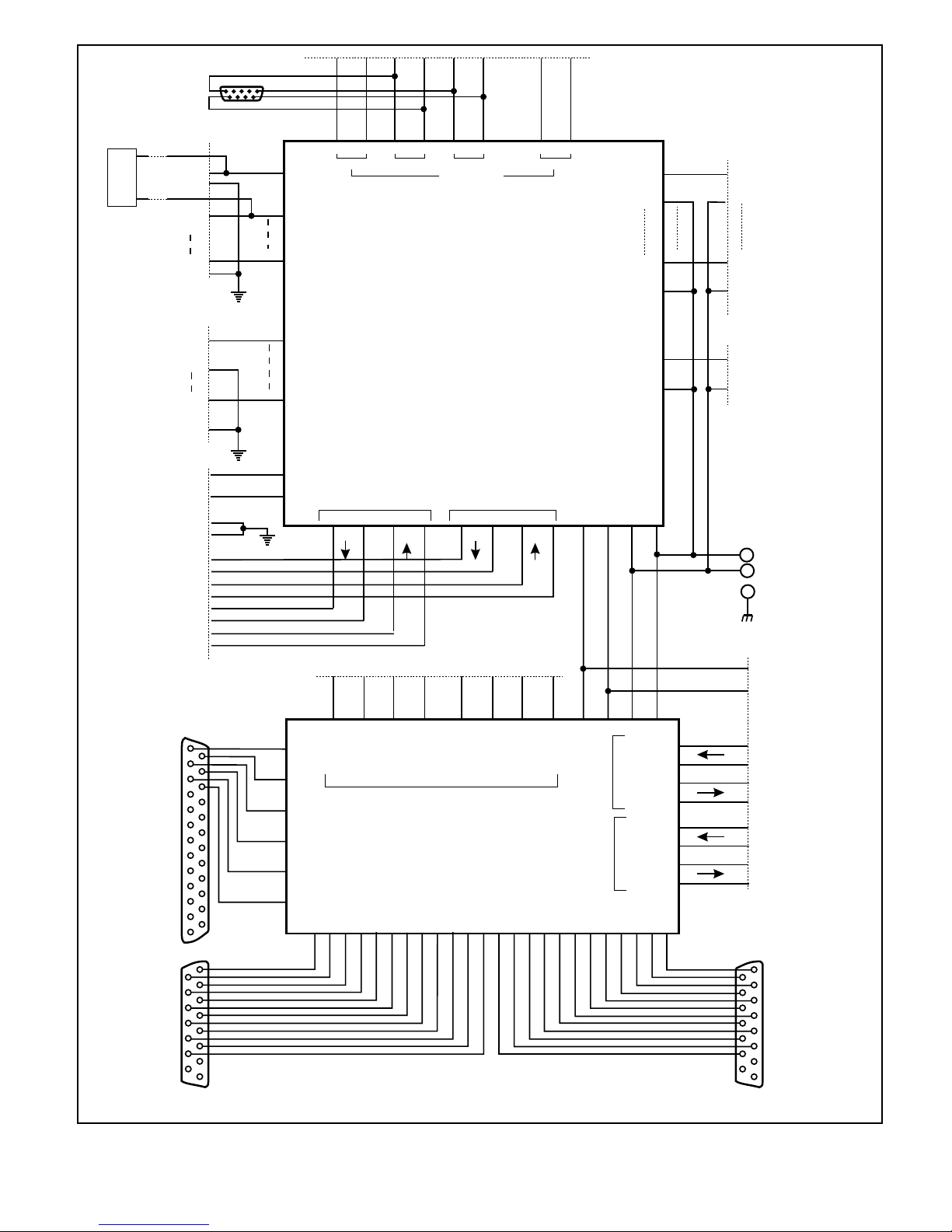
Fig. 8 - Terminal package is wired to accept KDA network element or FDO 3000 Off-Net plug-in card.
D-PG-413-11C-00 9 UM118129
August 11, 1999
DPS Telecom
DVF-64
DPC-64
FA MOD 8 7 56
FA
DPS Telecom
DPS INC.
Terminal Package
D-PC-413-11C-04
3-30-99
Page 9
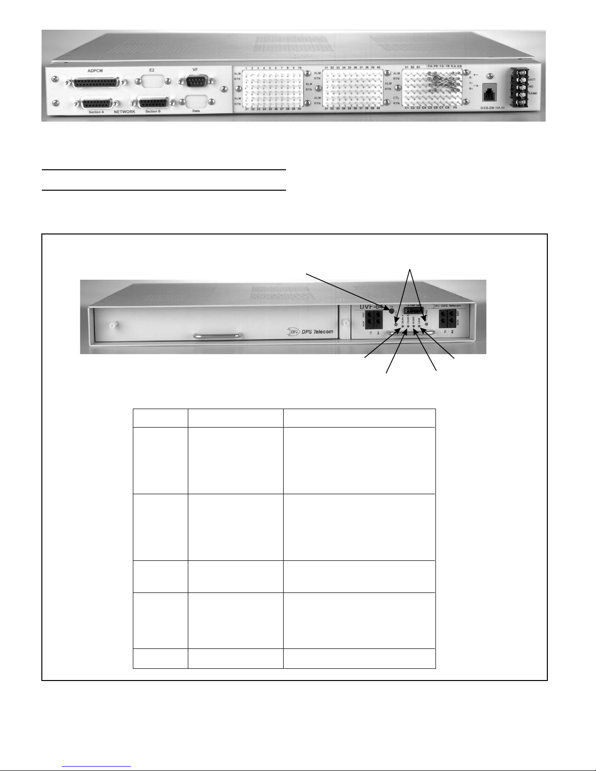
Fig. 9 - Back panel provides wire wrap connections for fuse alarm, VF and digital ports.
Network interfaces at DB15 connectors. (See Fig. 6 for pin-out information.) ADPCM and VF connectors are used
with other applications.
Installation (Cont.)
11. Set DIP switch. (See Fig. 5.)
12. Replace card.
LED
Channel A
13. Replace fuses
14. Test shelf.
Transmit Levels for VF ports
are factory calibrated - Adjust only
Fuse Alarm
if directed by DPS Tech Support
Channel A
Table C - DVF-64 Led Meanings
Color
OFF
Solid GRN
Flashing GRN
Flashing RED
Flashing RED/GRN
Meanings
Channel Off
Channel active
Loss of transmit sync
Loss of receive sync
Loss of both channels
Link
Channel B Mode
Channel B
OFF
Solid GRN
Flashing GRN
Flashing RED
Flashing RED/GRN
Mode
OFF
Solid RED
Link
OFF
Flashing GRN
Flashing RED
Flashing RED/GRN
Fuse Alarm
Solid RED
Fig 10 - KDA LCD and LEDs indicate real-time status of alarms and controls and perform diagnostics. LEDs on
UM118129 10 D-PG-423-11C-04
Channel Off
Channel active
Loss of transmit sync
Loss of receive sync
Loss of both channels
Repeater switch Off
Repeater switch On and bridged
No TABS
64 Kbit section A active
64 Kbit section B active
Both sections being polled
Blown Fuse
DVF-64 show channel status.
August 11, 1999
Page 10
Wire-Wrap
Block C3
3C1 C2
Jack
RJ-12
Phone line
D1 D24
Add jumpers
at W/W block
C3 to convert
to FDO 3000
Off-Net
Wire-Wrap
C1-1A
C1-1B
C1-2A
C1-2B
C1-10E
C1-10F
Wire-Wrap
Block C2
C2-1A
C2-1B
C2-6E
5
Block C1
DB9 Male
9
VF
1
6
P1-1
P1-2
P1-30
P1-31
P1-56
1E 1F 2E 2F 3E 3F 8E 8F
P2-21
P2-20
P2-19
P2-18
P2-17
BABABA BA
Alarm
Points
2-30
12 3 8
Control Points
KDA 864-E2A
or
KDA 864-TABS
Alarm
Points
31-56
(P1 & P2)
or
FDO 3000 Off-Net
P2-22
P2-31
P2-32
W/W Block
C3
Alarm
Point
57
Alarm
Point
60
Alarm
Point
61
Alarm
Return
Alarm
Return
Alarm
Return
P2-1
P2-2
P2-7
P2-8
P2-9
P2-10
Wire-Wrap
Block C2
C2-7E
C2-7F
C2-10E
C2-10F
Wire-Wrap
Block C3
C3-1A
C3-1B
DB25 Female
to ADPCM
C2-6F
W/W Block C3
C3-9E
C3-9F
C3-9E
C3-10E
C3-10C
C3-10D
C3-10A
C3-10B
C3-9C
C3-9D
C3-9A
C3-9B
13
25
14
1
9
T1
R1
T
R
T1
R1
T
R
1
P2-47
P2-48
Shields
202 / RS422
Section A
P2-51
P2-49
P2-53
P2-54
5A 5B 5C 5D 6A 6B 6C 6D
26
25
36
35
DCP A IN-
DCP A IN+
DCP A OUT+
DCP A OUT-
TABS Ports (RS422)
TC TS TD RD RS RC RC RS RD TD TS TC
38
52
37
22
21
50
49
51
46
9
10
11
12
13
14
Satellite
C3-
SCLK +
SCLK -
SEN +
SEN -
SDAT +
SDAT -
RS422
Section B
P2-39
34
33
DCP B IN+
DVF-64
(P3)
45
47
48
P2-40
DCP B IN-
39
27
40
P2-37
DCP B OUT+
41
P2-38
28
42
DCP B OUT -
43
P2-45
Alarm
44
Fuse
Fuse
E2A Port
(202)
23
Alarm
P2-46
24
GND
-Batt.
P2-56
P2-55
555653 54
DVFAIN-
DVFAIN+
DVF A OUT -
DVF A OUT +
DVFBIN-
DVFBIN+
DVF B OUT -
DVF B OUT +
29
30
31
Alarm
Point
64 is not
wired
Power
Barrier
-Batt.
GND
Frame
Gnd.
W/W Block C3
C3-9F
Fuse
Alarm
C3-10F
2
1
4
3
8
7
6
5
---+++-++-+-+-----++++-+
32
7B
7A
7D
w/DVF Card
7C
8A
KDA 864-TABS
8B
8C
8D
Block Diagram, Type III Shelf
KAD 864-E2A,
or FDO 3000 Off-Net
2-25-99 CDH
1
9
DB15 Female
Network
Section A
15
Fig. 11 - Inner-Shelf wiring is completed at the factory. Shelf is wired for future KDA plug-in.
D-PG-413-11C-00 11 UM118129
August 11, 1999
DB15 Female
Network
Section B
15
Page 11
64 Kbit
Digital
Section A
64 Kbit
Digital
Section B
24 Kbit
Port to ADPCM
Processor
Note 1
Note 2
32 Kbit Port
CODEC
CODEC
Term.
SW 1
Note 3
Rptr.
Te st
Jacks
Te st
Jacks
Te st
Jacks
Te st
Jacks
Port A
(202)
Ports
Port B
VF
NOTES:
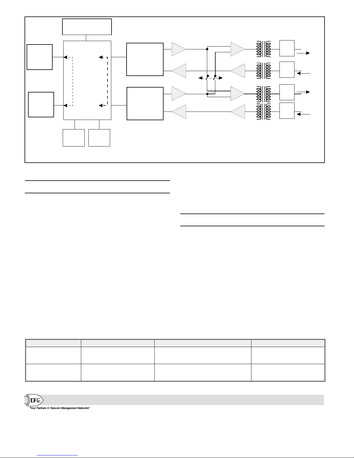
1. 8 Kbit (TABS) and 2 (order-wire voice) d loops between A and B sections
8 Kbit
RS 422
Port A
8 Kbit
RS 422
Port B
when bothsections are ON (SW 1-1 and SW 1-2 on).
2. 32 Kbit data (E2A from VF port) loops between A and B sections when SW 2-3 is on.
3. With SW 1 in Term. position, VF ports are summed at the CODEC (ports do not communicate with each other at
the VF side). With SW 1 in Rptr. Position, VF ports are bridged (ports communicate with each other at the VF side).
Fig. 12 - DVF-64 Functional Schematic.
Specifications
Dimensions: 17.0"(W) X 12.0"(D) X 1.75"(H)
Mounting: The unit can be mounted
in a 19" or 23" rack. Rack mounting ears
can be located for flush mounting, for
1/2” projection or for 5" projection
mounting. The DVF-64 card fits in
expansion card slot of KDA housing.
Back Panel Interface:
3-Wire Wrap Blocks,
One Power Terminal Block
2 DB15 network
1 DB25 ADPCM
1 DB9 VF
Power Input: Power input is -36 to -72 VDC.
Current Requirement is 80 MA
@ -48 VDC.
Fuse: 1/4 Amp
Table D - Packages that use the 413 Terminal Package
4 Kbit ata
Operating Temperature Range:
0 Degrees to +60 Degrees Celsius
Humidity: 0% to 95% non-condensing.
Operational Modes: Terminal and Repeater.
Model Numbers
D-PG-413-11C-04: Digital Base Terminal Package, Eq. w/
DVF-64 card, -48 VDC.
D-AS-00080-10A KDA 864-E2A P.C. assembly (to add
E2A network element to the Digital
Base Terminal package).
D-AS-00080-30A KDA 864-TABS P.C. assembly (to add
TABS network element to the Digital
Base Terminal package).
D-PC-801-11C-04 FDO 3000 Off-Net P.C. assembly (to
add off-net. Requires Order-Wire and
ADPCM in companion shelf (414
package - see Table D).
D-PC-803-11C-04 DVF Card (spare)
Part Number Package Name Components Other Manuals
D-DG-605-11C-04 Satellite Terminal w/ Order-Wire FDO 1000 / Phone / Speaker / ADPCM
D-PG-414-11C-04 Order-Wire and Off-Net Expansion
(to add to 413 to make a 410 package)
NOTE: Fig. 6 shows how packages can be expanded.
DPS Telecom
UM118129 12 D-PG-423-11C-04
4955 E. Yale - Fresno, CA 93727 - Phone: (559) 454-1600 / (800) 622-3314 - FAX: (559) 454-1688
Blank module / DVF-64
(2 Housings)
FDO 1000 / Phone / Speaker / ADPCM
FDO 3000 (card only)
(1 additional Housing)
e-mail: [email protected]
Visit our Web site at http://www.dpstele.com
UM110339
UM110339
UM117239
August 11, 1999
 Loading...