

Page 1
DPS Telecom
“Your Partners in Network Alarm Monitoring”
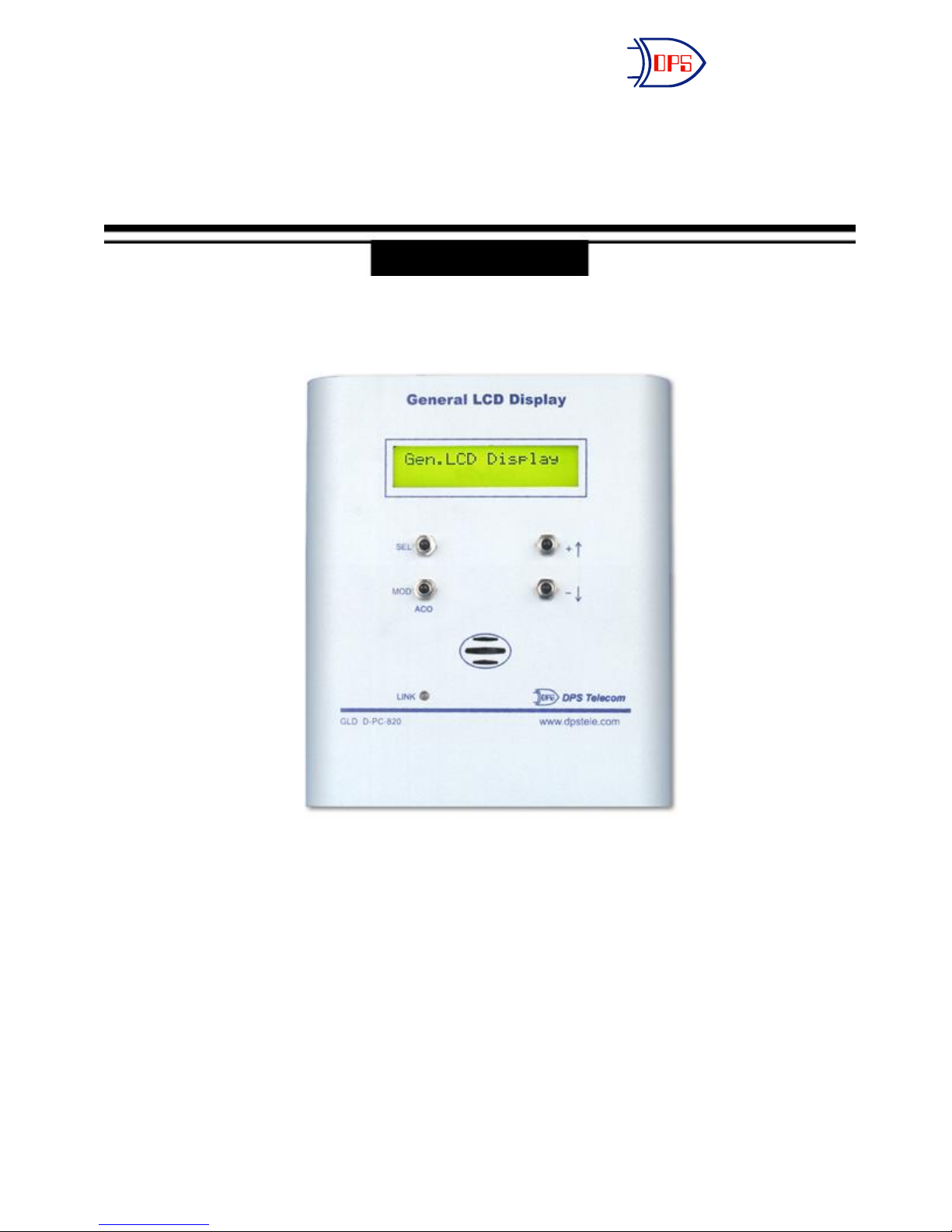
General LCD Display (GLD)
USER MANUAL
Visit our website at www.dpstelecom.com for the latest PDF manual and FAQs.
June 2, 2010
D-OC-UM106.02100
Version 1.0F
Page 2

Revision History
June 2, 2010
March 28, 2008
Updated pinouts for RS485/422 and RS232 GLD versions.
Converted to H&M4 and added G4 and G5 connection sections
This document contains proprietary information which is protected by copyright. All rights are reserved. No part of this
document may be photocopied without prior written consent of DPS Telecom.
All software and manuals are copyrighted by DPS Telecom. Said software and manuals may not be reproduced, copied,
transmitted or used to make a derivative work, by either mechanical, electronic or any other means in whole or in part,
without prior written consent from DPS Telecom, except as required by United States copyright laws.
© 2010 DPS Telecom
Notice
The material in this manual is for information purposes and is subject to change without notice. DPS Telecom shall not be
liable for errors contained herein or consequential damages in connection with the furnishing, performance, or use of this
manual.
Page 3

Contents
Visit our website at www.dpstelecom.com for the latest PDF manual and FAQs
Overview1 1
Summary of Features1.1 1
Description1.2 1
Shipping List1.2.1 2
Hardware2 3
Specifications2.1 3
GLD Connections2.2 4
Setting the Internal Address (v1.0D or older)2.2.1 4
Setting the Internal Address & Baud Rate (v1.0E or newer)2.2.2 5
2.2.2.1
LED Indications2.2.3 5
Audible Notification2.2.4 5
LCD Operation2.2.5 5
Host Connections2.3 6
Multiple GLDs2.3.1 6
Setting Baud Rate
5
KDA Connection2.3.2 7
2.3.2.1
NetGuardian Connection2.3.3 9
2.3.3.1
2.3.3.2
2.3.3.3
IAM Connection2.3.4 13
T/MonXM Connection2.3.5 14
2.3.5.1
KDA Software Configuration
NetGuardian G2 Web Browser configuration
NetGuardian G4 Web Browser Configuration
NetGuardian G5 Web Browser configuration
T/MonXM Software Configuration
8
10
11
12
15
Page 4

Page 5

Overview1
Summary of Features1.1
• View system status remotely
• Multiple display capabilities
• Speaker for audible notification
• Detailed alarm indication messages
Description1.2
The General LCD Display (GLD) allows the user to monitor an existing network from different locations by
providing
remote visibility of the system’s status. This convenient method of monitoring gives the user the ability to
monitor the network without being physically present at the system site. With detailed alarm indication messages,
the GLD gives peace of mind to network managers who aren’t able to constantly observe the system’s status from
the network’s location.
1
The GLD can easily “daisy-chain” from unit to unit. This means that up to 3 GLDs can be connected to a single
host, with a maximum range of 1,500 feet between the host and the last GLD unit (the 1,500 foot maximum
applies
to a single GLD as well). The GLD is also easy to install, with connectors for all ports and mounting screws for
easy
attachment to any flat vertical surface.
Along with the convenience of remote visual monitoring, the unit is equipped with a speaker for audible
notification.
The unit will sound when certain conditions occur, keeping the network manager informed of the system’s status
even when the unit is not being watched. Additionally, the Link LED on the face of the GLD indicates
communication
with the host. A red flash indicates receive activity while a green flash shows transmit activity.
With detailed alarm messaging, multiple display capabilities and easy installation, the GLD is a simple solution
to a network manager’s remote monitoring needs.
Page 6
2
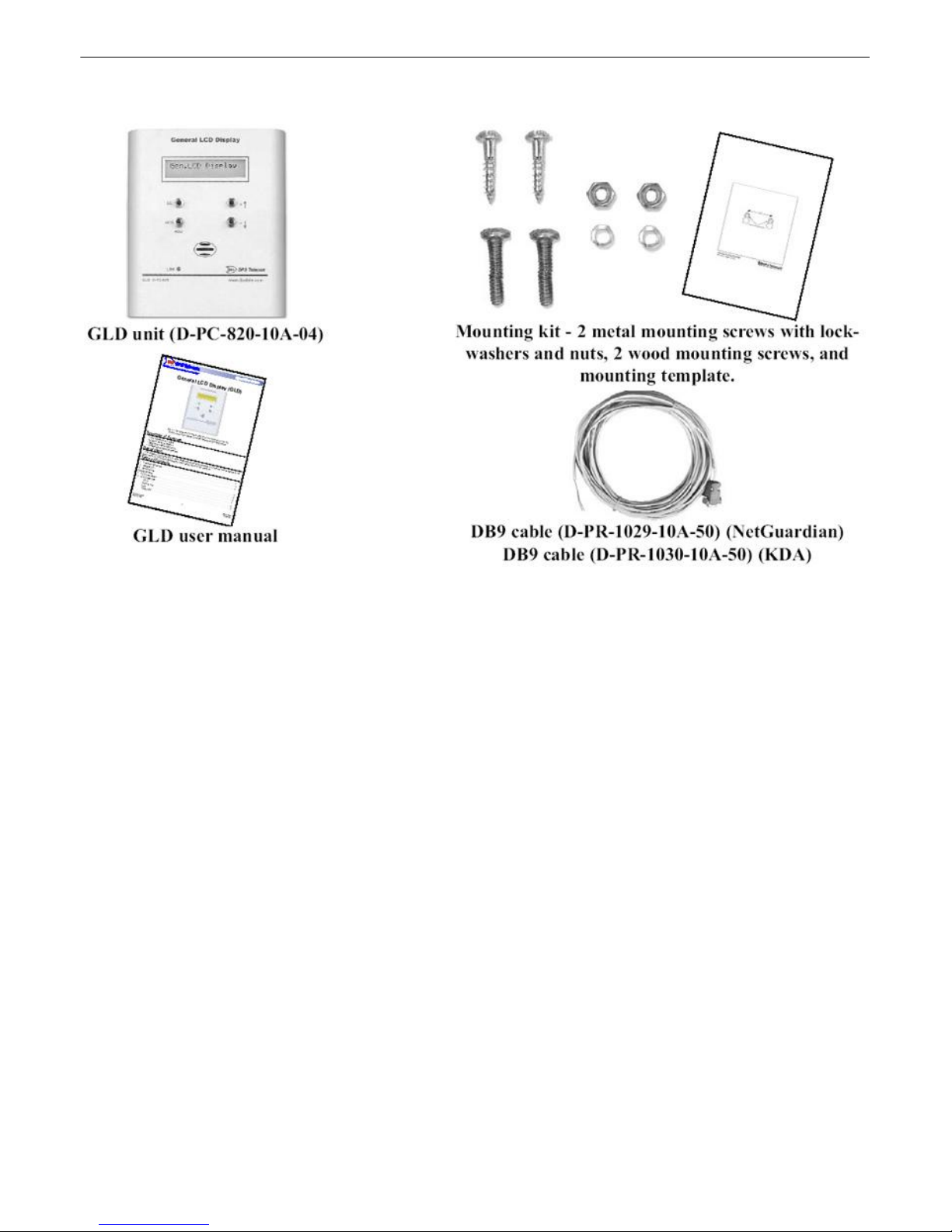
1.2.1 Shipping List
Page 7

3
Dimensions:
5 1/8”H x 5”W x 1 1/2”D
Power Input:
-48VDC
Current draw:
100mA
Fuse:
Internal
Interface:
RS485
Operating
Temperature
Range:
0 to +60 degrees Celsius (+32 to +140 degrees Fahrenheit)
Operating
Humidity Range:
0% to 95% non-condensing
Mounting:
Keyhole pattern on back for attachment to mounting screws (included)
Hardware2
Specifications2.1
Page 8
4
WARNING
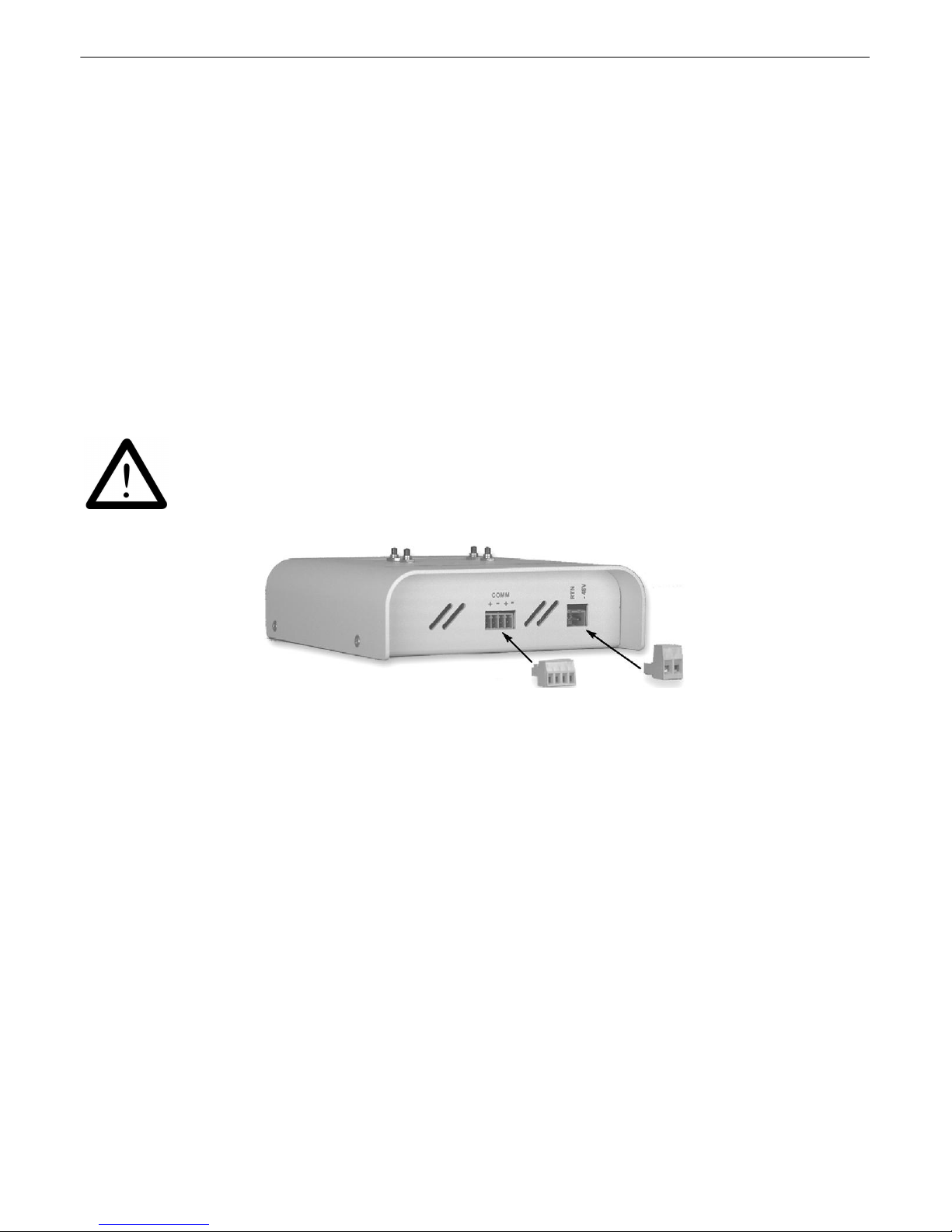
Fig. 2.2 - GLD barrier terminals
GLD Connections2.2
1) Mount the GLD in the desired location using the mounting template and the mounting screws provided. Position
the case onto the screws then slide it down to lock into place.
2) Remove the screw-lug barrier plugs from the bottom of the GLD. (See figure 2.2)
3) Connect communication wires from the host to the ‘IN’ terminals of the 4 position barrier plug. (See figure 2.2)
If daisy chaining, connect communication wires from the ‘OUT’ terminal to the ‘IN’ terminal of the next GLD.
The ‘+’ and ‘-’ ports are universal and therefore either side may be used as an “IN” port or an “OUT” port. (See
figure 2.2.1) (Requires small standard screwdriver to work with small connectors)
4) Connect a -48VDC power lead and a GND lead to the corresponding terminals of the 2-position barrier plug.
5) All barrier screws should be seated firmly but not over-tightened so as to nick the bare wire.
6) Push the plugs firmly back into their appropriate location on the bottom of the case.
7) Once the hardware connections are complete, power the unit(s) by applying -48VDC to the power lead.
Always observe electrostatic discharge (ESD) precautions
2.2.1 Setting the Internal Address (v1.0D or older)
Each unit must have a separate internal address. The address is stored internally and only needs to be set once
prior to use.
To set the internal address:
1). Enter Set Address mode by simultaneously holding down the + and – buttons.
2). Use the up or down arrows to choose the desired address from the Set Address menu.*
e.g.: GLD Addr: 2
+/- to change
3). Press SEL to accept the displayed address. An asterisk (*) will appear next to the address you have accepted.
e.g.: GLD Addr: 2*
MOD to exit
4). Press MOD to exit Set Address mode.
Page 9

2.2.2 Setting the Internal Address & Baud Rate (v1.0E or newer)
Each unit must have a separate internal address. The address is stored internally and only needs to be set once
prior to use.
To set the internal address:
1). Enter Set Address mode by simultaneously holding down the + and – buttons.
2.) To set address press select.
3). Use the +/- buttons to choose address.
3). Press SEL to accept the displayed address. An asterisk (*) will appear next to the address you have accepted.
e.g.: GLD Addr: 2*
4). Press MOD to exit Set Address mode.
2.2.2.1 Setting Baud Rate
To set the baud rate:
5
1). Enter Set baud rate mode by simultaneously holding down the + and – buttons.
2.) Press +, you will see "GLD baud".
3). Press SEL, then use the +/- buttons to adjust baud rate.
3). Press SEL to set.
4). Press MOD to exit.
2.2.3 LED Indications
The Link LED indicates communication with the host. A red flash shows receive activity, while a green flash shows
transmit activity.
A slow red blink represents a communication link idle for more than 2 minutes, which is considered a
communication failure. The LCD will show “Link Down.”
2.2.4 Audible Notification
The host may activate the GLD speaker as certain conditions occur. Press the MOD/ACO button to locally
terminate the sound.
2.2.5 LCD Operation
Refer to the host’s manual for specific operation details.
* If using only 1 GLD unit, the address must be set to 1.
Page 10
6
Host Connections2.3
The GLD can be connected to the KDA (page 7), the NetGuardian (page 9), the NetGuardian G4 (page 11), the
NetGuardian G5 (page 12), the IAM (page 14) or T/MonXM (page 15).
Note: There are host version requirements to connect the GLD. See the individual host sections in this manual for
specific minimum version requirements.
2.3.1 Multiple GLDs
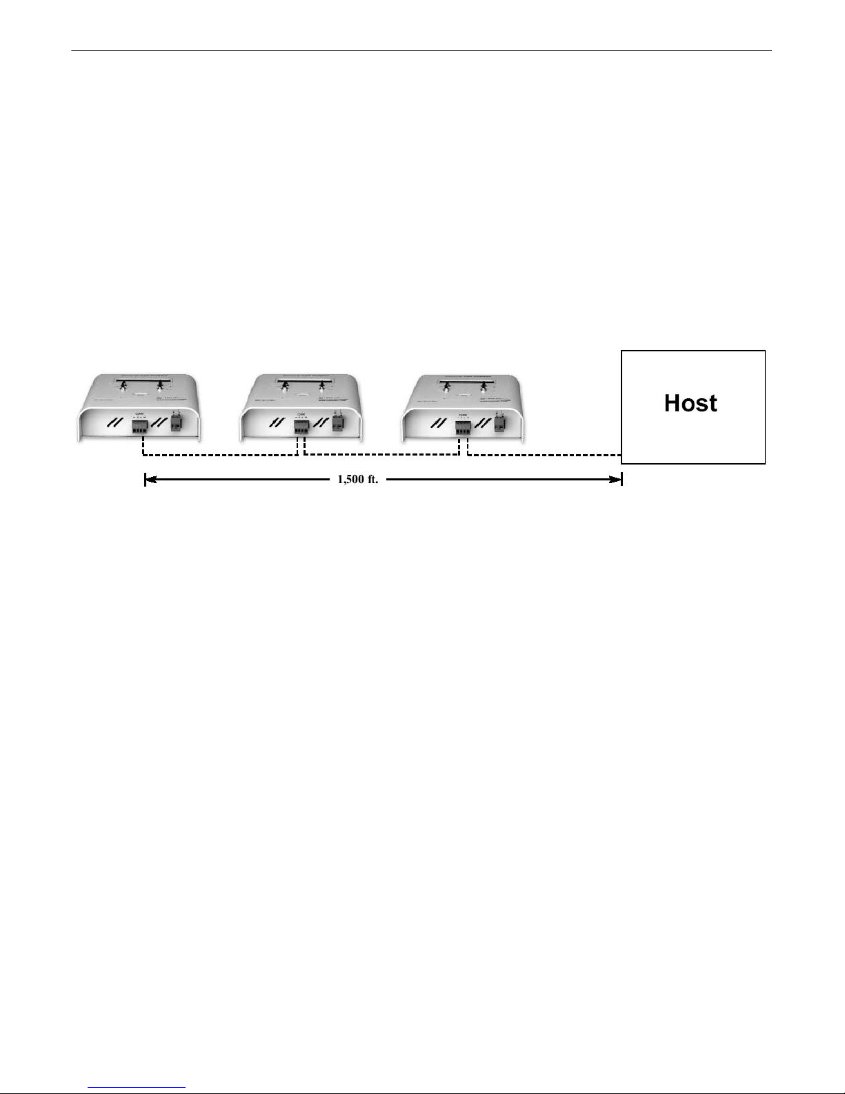
Up to twelve GLDs can be installed at one site. The units can be connected to a host in a daisy chain
configuration as shown in the figure below or in a star configuration. Whether connecting 1, 2, or 12
GLD units to the host, the maximum connection length is 1,500 feet. The ‘+’ and ‘-’ from the host
channel are connected to the ‘IN’ side of the communication plug on the bottom of the GLD. The ‘OUT’
side of the communication plug is for daisy chaining to other GLDs.*
* The ‘+’ and ‘-’ ports are universal and therefore either side may be used as an “IN” port or an “OUT” port.
Page 11
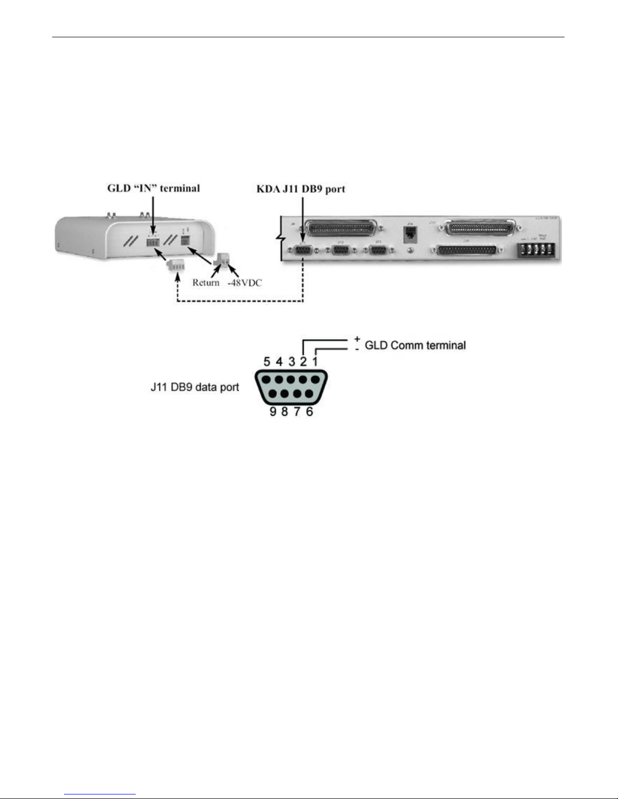
2.3.2 KDA Connection
Fig. 2.3.2a - Communication lines between the KDA and GLD
Fig. 2.3.2b - KDA J11 pinout to GLD
1). Connect communication wires from the J11 DB9 female connector on the back panel of the KDA. (See figure
2.3.2a)
2). From the J11 data port on the KDA, connect the communication wires to the 4 position barrier plug of the GLD.
Pin 1 is connected to the negative terminal of the GLD and pin 2 is connected to the positive terminal of the GLD.
(See figure 2.3.2b and table A)
Note: KDA Time Stamp version 1.7D and above is required to connect the GLD.
7
Table A - J11 pinout information to GLD
J11 Pin # GLD Comm terminal Wire Color
1 Negative (-) Blue/White
2 Positive (+) White/Blue
Page 12
8
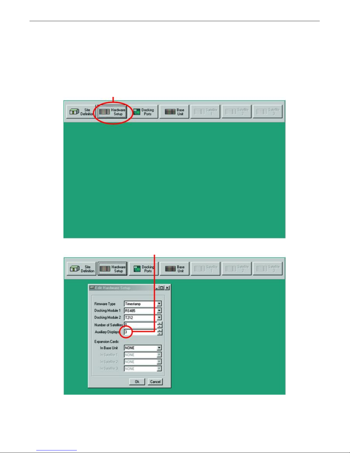
Fig. 2.3.2.1a - "Hardware Setup" can be accessed from the main screen
Fig. 2.3.2.1b - The "Edit Hardware Setup" menu pops up when the "Hardware Setup" button is
selected
2.3.2.1 KDA Software Configuration
1). From the main menu screen, select “Hardware Setup”. (See figure 2.3.2.1a)
2). From the “Edit Hardware Setup” pop-up window, enter the number of GLD units you are connecting (1-3) in the
“auxiliary displays” section and press “OK”. (See figure 2.3.2.1b)
Note: The Firmware type must be set to “Timestamp” and Docking module 1 must be set to “RS485”. (See figure
2.3.2.1b)
Enter the number of GLDs being connected
Page 13
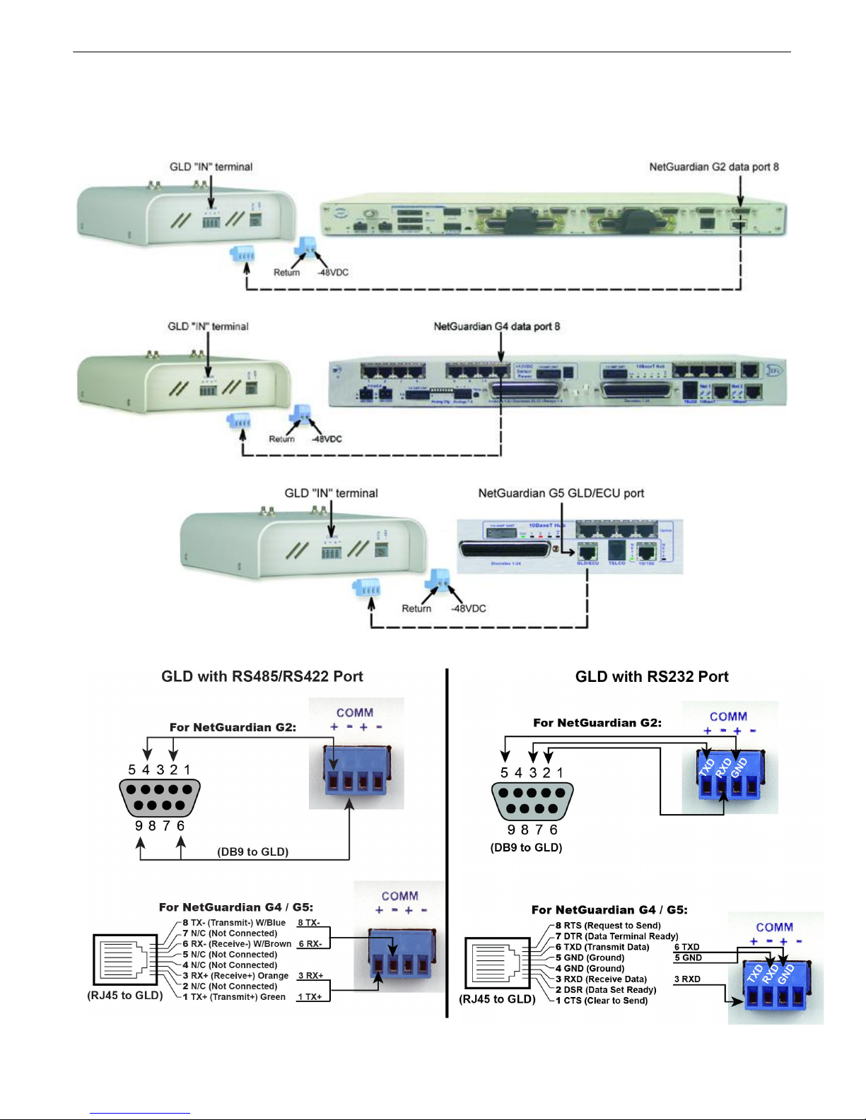
2.3.3 NetGuardian Connection
Communication lines between the NetGuardian G2 and GLD
Communication lines between the NetGuardian G4 and GLD
Communication lines between the NetGuardian G5 and GLD
Note: NetGuardian version 1.5C and above is required to connect the GLD. The NetGuardian must have an
RS485 or RS232 port for GLD support.
9
Page 14
10
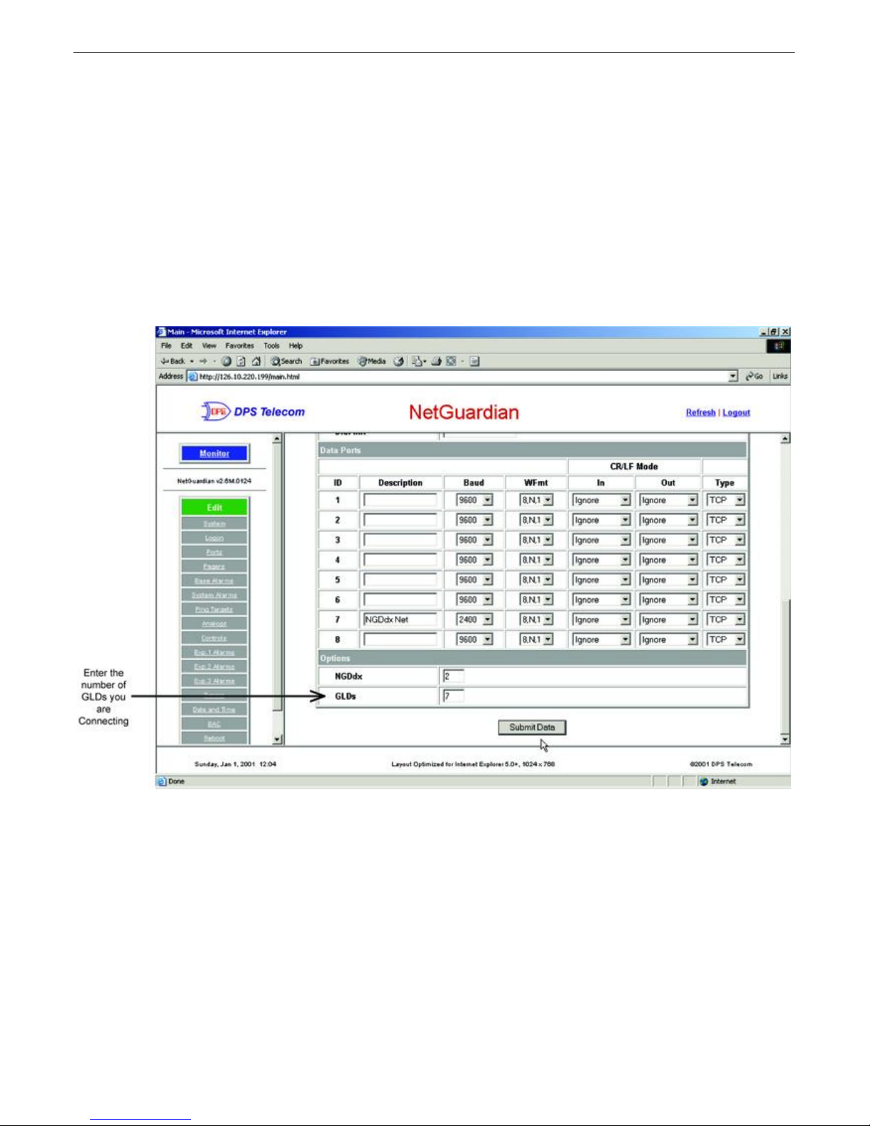
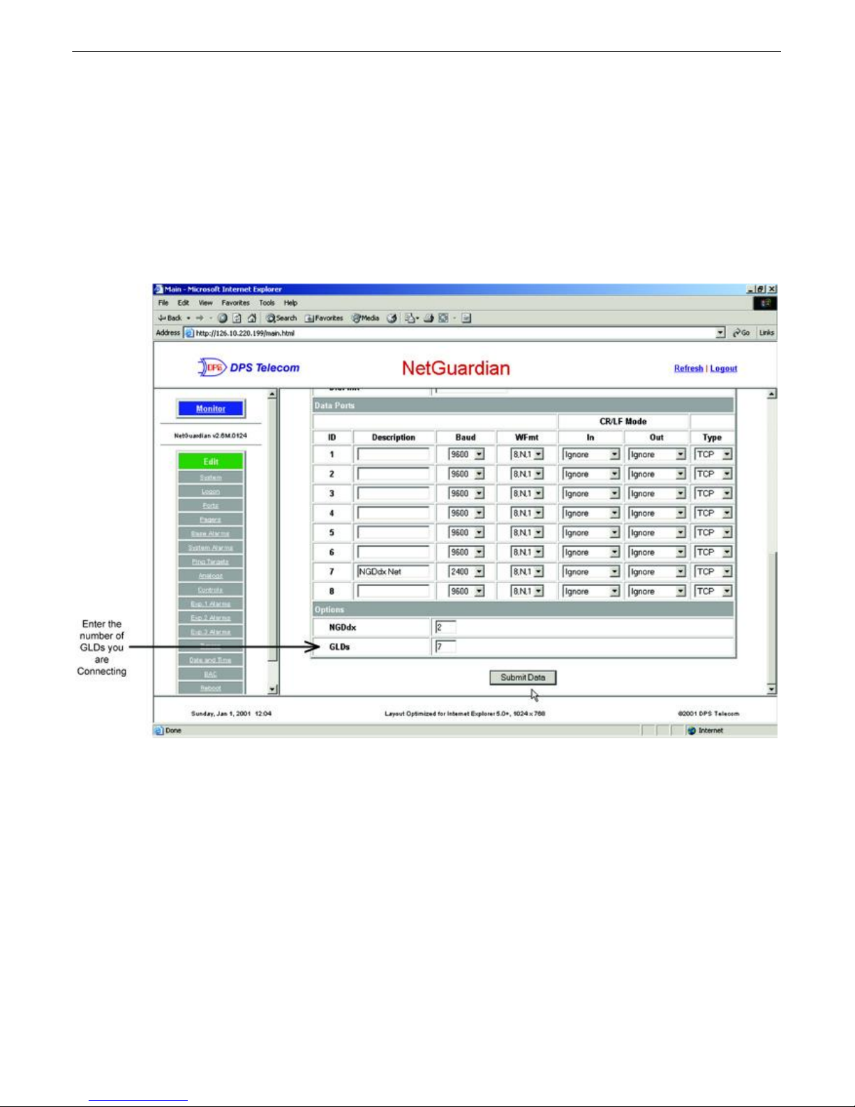
Fig. 2.3.3.1 - Web Browser configuration for connection to GLD
2.3.3.1 NetGuardian G2 Web Browser configuration
1). From the main screen, select “Edit” and then “Ports.”
2). Scroll down to the Options portion of the Ports screen.
3). Enter the number of GLDs you are connecting to the NetGuardian.
4). Hit the “Submit Data” button.
Note: If connecting more than 3 GLDs, set the NetGuardian baud rate to 9600 (see the NetGuardian user
manual).
Page 15
2.3.3.2 NetGuardian G4 Web Browser Configuration
Fig. 2.3.4.1 - Web Browser configuration for connection to GLD
1). From the main screen, select “Edit” and then “Ports.”
2). Scroll down to the Options portion of the Ports screen.
3). Enter the number of GLDs you are connecting to the NetGuardian G4.
4). Hit the “Submit Data” button.
Note: If connecting more than 3 GLDs, set the NetGuardian G4 baud rate to 9600 (see the NetGuardian G4
user manual).
11
Page 16
12
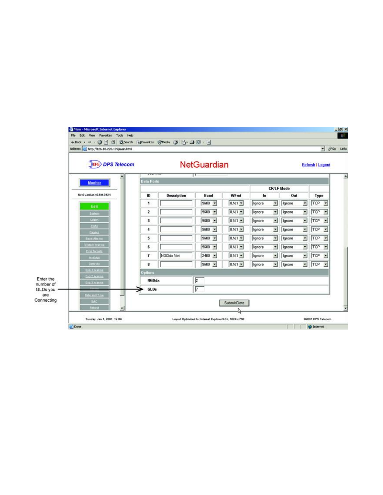
Fig. 2.3.5.1 - Web Browser configuration for connection to GLD
2.3.3.3 NetGuardian G5 Web Browser configuration
1). From the main screen, select “Edit” and then “Ports.”
2). Scroll down to the Options portion of the Ports screen.
3). Enter the number of GLDs you are connecting to the NetGuardian G5.
4). Hit the “Submit Data” button.
Note: If connecting more than 3 GLDs, set the NetGuardian G5 baud rate to 9600 (see the NetGuardian G5
user manual).
Page 17
2.3.4 IAM Connection
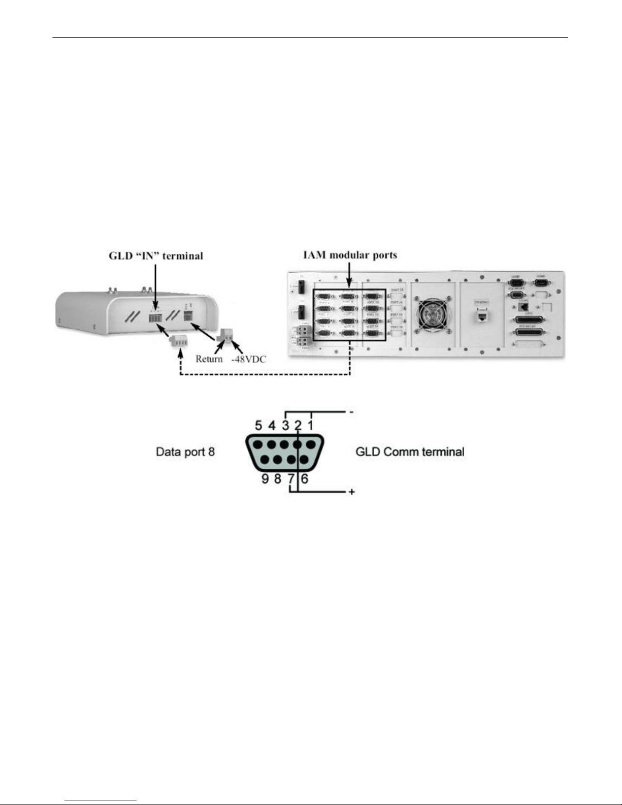
Fig. 2.3.6a - Communication lines between the IAM and GLD
Fig. 2.3.6b - IAM DB9 pins to GLD
1). Connect communication wires from a DB9 modular port on the back panel of the IAM. (See figure 2.3.6a)
2). From the DB9 port, connect the communication wires to the 4 position barrier plug of the GLD.
Pinout 1 = Rx-, Pinout 2 = Tx+, Pinout 3 = Tx-, and Pinout 7 = Rx+. (See figure 2.3.6b and table C)
3). Tie communication wires 2 and 7 together for connection to the positive terminal of the GLD and tie
communication
wires 1 and 3 together for connection to the negative terminal of the GLD.
4). For software configuration for the IAM, see the section in this manual regarding T/MonXM software
configuration
(pages 15 - 17).
Note: IAM version 3.5D1 and above is required to connect the GLD.
13
DB9 Pinout GLD Comm terminal Wire Color
1 Negative (-) White/Blue
2 Positive (+) Blue/White
3 Negative (-) White/Blue
7 Positive (+) Blue/White
Table C - DB9 pinout information to GLD
Page 18
14
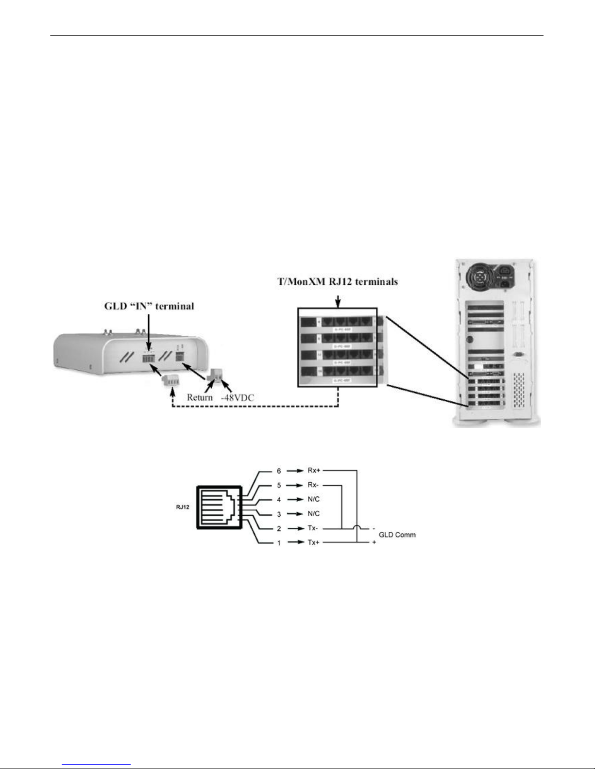
Fig. 2.3.7a - Communication lines between the T/MonXM and GLD
Fig. 2.3.7b - RJ12 pins to GLD
2.3.5 T/MonXM Connection
1). Connect communication wires from an RJ12 connection on the back panel of the T/MonXM. (See
figure 2.3.7a)
2). From the RJ12 connection, connect the communication wires to the 4 position barrier plug of the
GLD.
Wire 1 = O/W Tx+, Wire 2 = W/O Tx-, Wire 5 = W/B Rx-, and Wire 6 = B/W Rx+. (See figure 2.3.7b
and table D)
3). Tie communication wires 1 and 6 together for connection to the positive terminal of the GLD and tie
communication
wires 2 and 5 together for connection to the negative terminal of the GLD.
Note: T/MonXM version 3.5E and above is required for GLD support. T/MonXM must have the card
with the RS485 port to connect the GLD.
Table D - RJ12 pinout information
RJ12 Pinout GLD Comm terminal
1 Positive (+)
2 Negative (-)
5 Negative (-)
6 Positive (+)
Page 19
2.3.5.1 T/MonXM Software Configuration
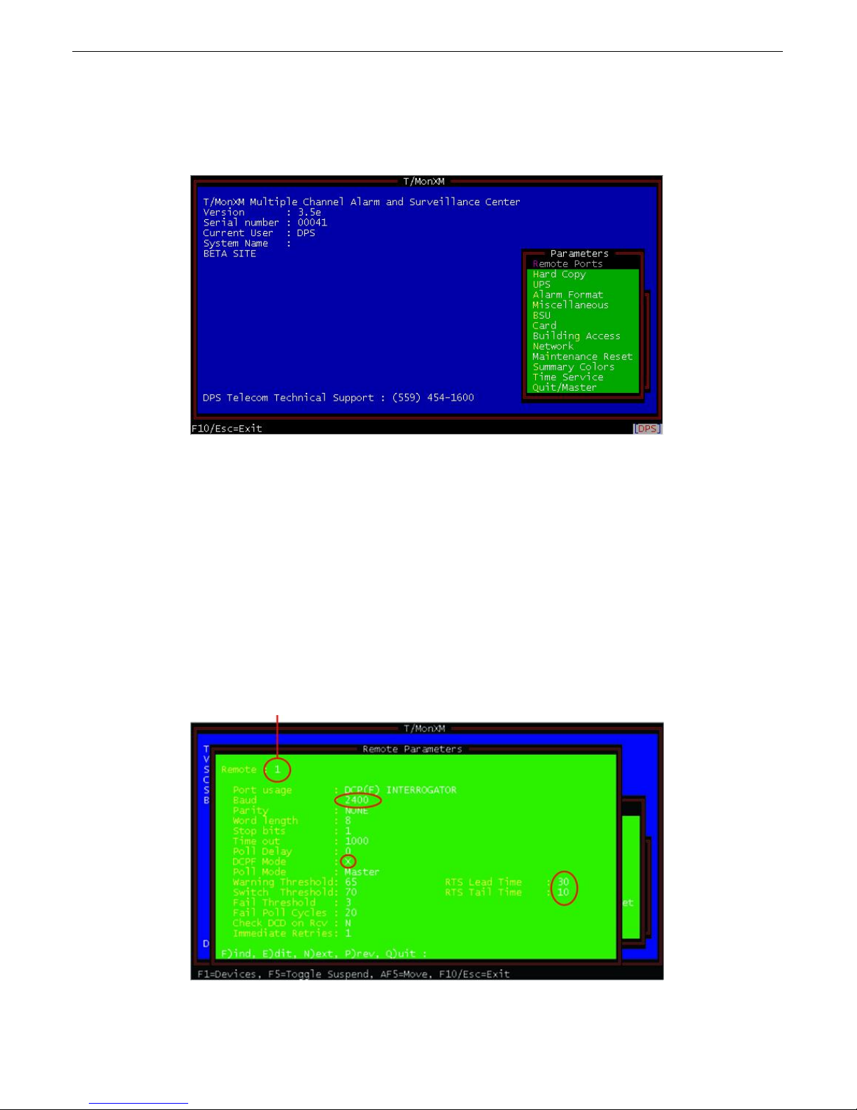
Fig. 2.3.7.1a - The parameters menu is available from the main menu
Fig. 2.3.7.1b - Enter the default settings in the Remove Ports screen except for the fields
highlighted above
1). From the main menu of T/MonXM, select the Parameters menu.
2). Select Remote Ports menu. (See figure 2.3.7.1a)
15
3). Select the data port you are plugging the GLD into by pressing F)ind and entering the number. (See figure
2.3.7.1b)
4). Select the E)dit Option. (See figure 2.3.7.1b)
5). Setup port usage for DCP(F) Interrogator (2400 BAUD). (See figure 2.3.7.1b)
6). Select Enter (Enter sets the automatic defaults) until you reach the DCPF Mode setting and type “X”. (See
figure 2.3.7.1b)
7). Resume selecting Enter (default) until you reach the RTS Time settings. (See figure 2.3.7.1b)
8). Set the RTS Lead to 30 and the RTS Tail to 10 and press enter again. (See figure 2.3.7.1b))
Physical communication line location (port number)
Page 20
16
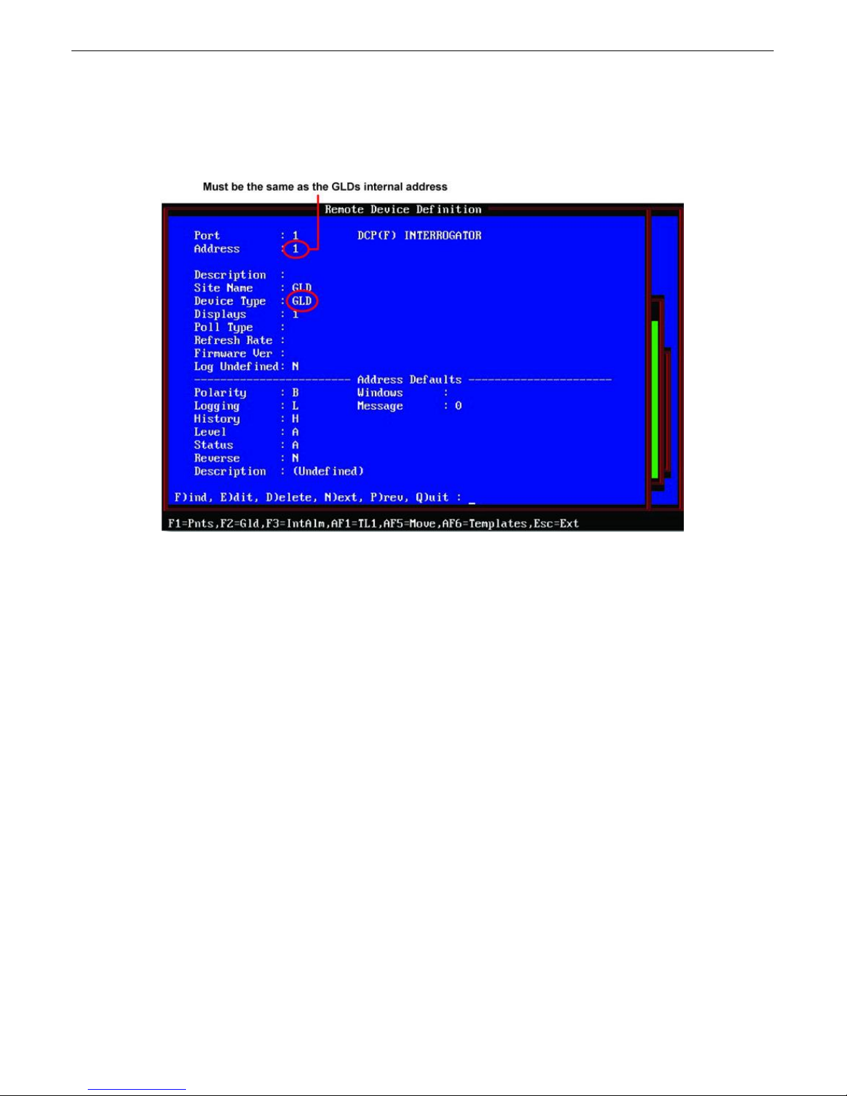
Fig. 2.3.7.1c - Enter the default settings in the Remote Device screen except for the fields
highlighted above
9). Select F1 for Devices. (See figure 2.3.7.1b)
10).Select the address for the GLD (must be either 1, 2 or 3). (See figure 2.3.7.1c)
11).At Device type, select GLD. (See figure 2.3.7.1c)
Model Numbers
General LCD Display (GLD): D-PC-820-10A-04
DB9 cable (NetGuardian): D-PR-1029-10A-50
DB9 cable (KDA): D-PR-1030-10A-50
DB9 cable (IAM): D-PR-1031-10A-50
RJ45 cable (NetGuardianG4/G5) D-PR-NGCBL-12003 (50')
D-PR-NGCBL-12004 (75')
D-PR-NGCBL-12005 (200')
Page 21

Page 22

Page 23

Warranty
DPS Telecom warrants, to the original purchaser only, that its products a) substantially conform to DPS' published
specifications and b) are substantially free from defects in material and workmanship. This warranty expires two years from
the date of product delivery with respect to hardware and ninety days from the date of product delivery with respect to
software. If the purchaser discovers within these periods a failure of the product to substantially conform to the specifications
or that the product is not substantially free from defects in material and workmanship, the purchaser must promply notify
DPS. Within reasonable time after notification, DPS will endeavor to correct any substantial non-conformance with the
specifications or substantial defects in material and workmanship, with new or used replacement parts. All warranty service
will be performed at the company's office in Fresno, California, at no charge to the purchaser, other than the cost of shipping
to and from DPS, which shall be the responsiblity of the purchaser. If DPS is unable to repair the product to conform to the
warranty, DPS will provide at its option one of the following: a replacement product or a refund of the purchase price for the
non-conforming product. These remedies are the purchaser's only remedies for breach of warranty. Prior to initial use the
purchaser shall have determined the suitability of the product for its intended use. DPS does not warrant a) any product,
components or parts not manufactured by DPS, b) defects caused by the purchaser's failure to provide a suitable installation
environment for the product, c) damage caused by use of the product for purposes other than those for which it was designed,
d) damage caused by disasters such as fire, flood, wind or lightning unless and to the extent that the product specification
provides for resistance to a defined disaster, e) damage caused by unauthorized attachments or modifications, f) damage
during shipment from the purchaser to DPS, or g) any abuse or misuse by the purchaser.
THE FOREGOING WARRANTIES ARE IN LIEU OF ALL OTHER WARRANTIES, EXPRESS OR IMPLIED,
INCLUDING BUT NOT LIMITED TO THE IMPLIED WARRANTIES OF MERCHANTABILITY AND FITNESS FOR
A PARTICULAR PURPOSE.
In no event will DPS be liable for any special, incidental, or consequential damages based on breach of warranty, breach of
contract, negligence, strict tort, or any other legal theory. Damages that DPS will not be responsible for include but are not
limited to, loss of profits; loss of savings or revenue; loss of use of the product or any associated equipment; cost of capital;
cost of any substitute equipment, facilities or services; downtime; claims of third parties including customers; and injury to
property.
For an additional fee DPS may, at its option, make available by written agreement only an extended warranty providing an
additional period of time for the applicability of the standard warranty.
Technical Support
If a purchaser believes that a product is not operating in substantial conformance with DPS' published specifications or there
appear to be defects in material and workmanship, the purchaser should contact our technical support representatives. If the
problem cannot be corrected over the telephone and the product and problem are covered by the warranty, the technical
support representative will authorize the return of the product for service and provide shipping information. If the product is
out of warranty, repair charges will be quoted. All non-warranty repairs receive a 90-day warranty.
Page 24
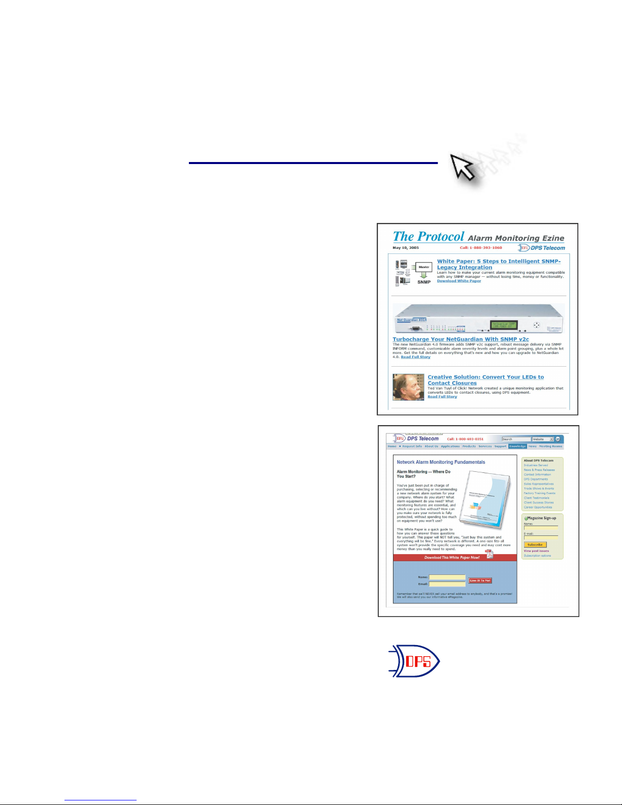
Free Tech Support is Only a Click Away
Need help with your alarm monitoring? DPS Information Services are ready to
serve you … in your email or over the Web!
www.DpsTelecom.com
Free Tech Support in Your Email: The Protocol Alarm Monitoring Ezine
The Protocol Alarm Monitoring Ezine is your free email
tech support alert, delivered directly to your in-box
every two weeks. Every issue has news you can use
right away:
Expert tips on using your alarm monitoring
•
equipment — advanced techniques that will save
you hours of work
Educational White Papers deliver fast informal
•
tutorials on SNMP, ASCII processing, TL1 and
other alarm monitoring technologies
New product and upgrade announcements keep
•
you up to date with the latest technology
Exclusive access to special offers for DPS
•
Telecom Factory Training, product upgrade offers
and discounts
To get your free subscription to
The Protocol register online at
www.TheProtocol.com/register
Free Tech Support on the Web: MyDPS
MyDPS is your personalized, members-only online resource.
Registering for MyDPS is fast, free, and gives you exclusive
access to:
• Firmware and software downloads and upgrades
• Product manuals
• Product datasheets
• Exclusive user forms
Register for MyDPS online at
DPS Telecom
“Your Partners in Network Alarm Monitoring”
www.DpsTelecom.com/register
(800) 622-3314 • www.DpsTelecom.com • 4955 E. Yale Avenue, Fresno, California 93727
 Loading...