

Page 1
DAC-P
USER MANUAL
“Your Partners in Network Alarm Management”
Visit our website at www.dpstelecom.com for the latest PDF manual and FAQs.
February 13, 2003 D-OC-UM032.13200 Firmware Version 1.0D
Page 2

Revision History
12/20/02
2/11/03 Second Preliminary Manual
2/13/03 Third Preliminary Manual
First Preliminary Manual
This document contains proprietary information which is protected by copyright. All rights are reserved. No part of this
document may be photocopied without prior written consent of DPS Telecom.
All software and manuals are copyrighted by DPS Telecom. Said software and manuals may not be reproduced, copied,
transmitted or used to make a derivative work, by either mechanical, electronic or any other means in whole or in part,
without prior written consent from DPS Telecom, except as required by United States copyright laws.
© 2003 DPS Telecom
Notice
The material in this manual is for information purposes and is subject to change without notice. DPS Telecom shall not be
liable for errors contained herein or consequential damages in connection with the furnishing, performance, or use of this
manual.
Page 3

Contents
Visit our website at www.dpstelecom.com for the latest PDF manual and FAQs
Introduction1 ................................................................................................1
Shipping List2 ................................................................................................1
Specifications3 ................................................................................................3
Operation4 ................................................................................................3
Installation5 ................................................................................................5
Tools Needed5.1 ................................................................................................5
Mounting5.2 ................................................................................................6
Power Connection5.3 ................................................................................................6
Network Connections5.4 ................................................................................................7
Configuration6 ................................................................................................8
Craft Port6.1 ................................................................................................8
Terminal Interface6.2 ................................................................................................9
Assigning an IP Address6.3 ................................................................................................10
Configuration File6.4 ................................................................................................11
Uploading the Configuration File6.5 ................................................................................................12
Other Configuration Options6.6 ................................................................................................13
System6.6.1 ................................................................................................13
Logon6.6.2 ................................................................................................14
Timers6.6.3 ................................................................................................17
Date and Time6.6.4 ................................................................................................19
Modem6.6.5 ................................................................................................20
NVRAM6.6.6 ................................................................................................21
Monitoring7 ................................................................................................21
MEFA7.1 ................................................................................................22
Config List7.2 ................................................................................................23
Alert Log7.3 ................................................................................................24
Configuration File Upload Alerts7.3.1 ................................................................................................24
Remote Communication Alerts7.3.2 ................................................................................................25
Page 4

Dial RTU7.4 ................................................................................................26
Reboot RTU7.5 ................................................................................................28
Other Commands8 ................................................................................................29
Ping8.1 ................................................................................................29
Stats8.2 ................................................................................................30
Debug8.3 ................................................................................................31
Unused Commands8.4 ................................................................................................32
LCD Display and Menu9 ................................................................................................32
Front Panel LED Operation10 ................................................................................................32
Technical Support11 ................................................................................................33
Page 5
Introduction1
t
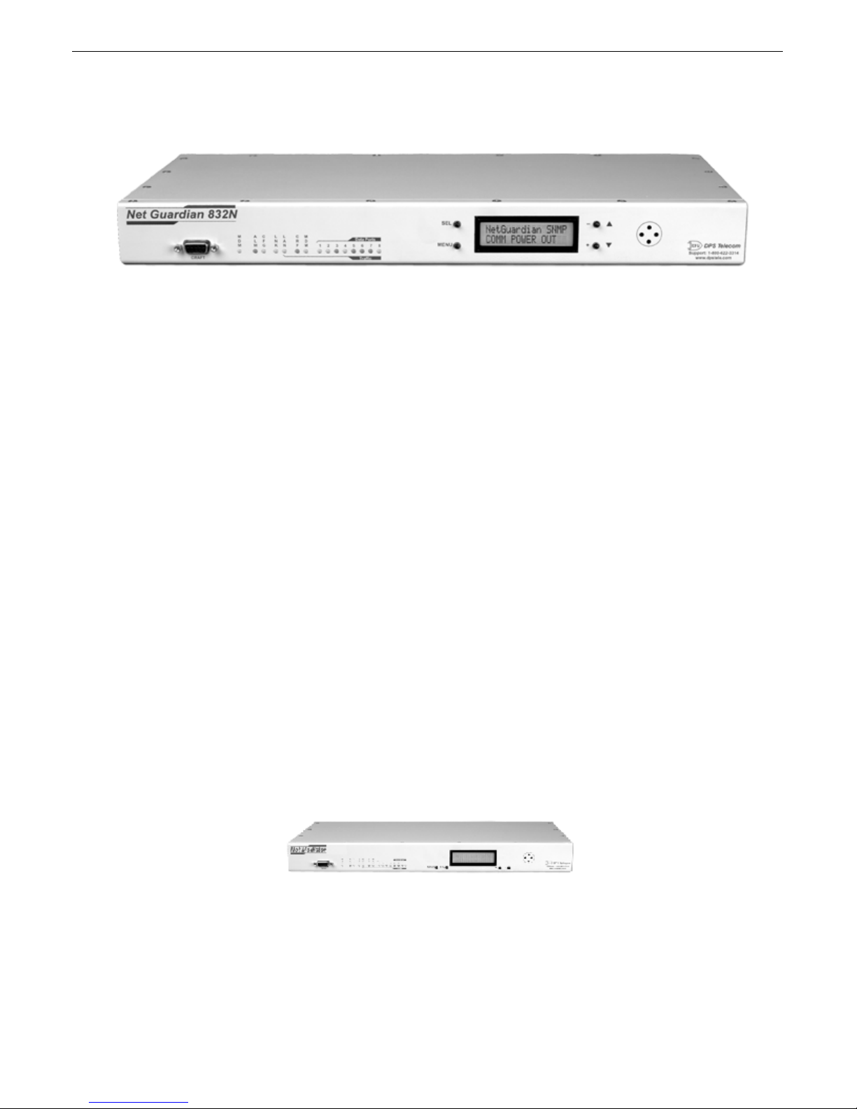
Fig. 1. The DAC-P
The DPS Telecom DAC-P serves as a mediator between remote telemetry units and the DPS Telecom Network Telemetry
Processor (NTP). The DAC-P collects alarm reports from remotes, maps remote data to a MEFA display grid, and forwards
the data through a four-port TABS responder to the NTP.
The DAC-P communicates with remotes through four dial-up modem lines. Either the DAC-P or one of its remotes can
initiate a dial-up connection. All four modem connections can be used simultaneously.
The DAC-P also provides central control for alarm collection remotes. The DAC-P manages dial-up connections, provisions
remotes with configuration data, provides extensive monitor visibility to help diagnose problems, and forwards control relay
and reboot commands from the NTP to remotes.
1
These control functions, plus alarm monitoring, are accessible remotely over a LAN/WAN connection or locally through a
craft port connection.
The DAC-P channels are provisioned via FTP with a configuration file derived from the TMAS database. Other
configuration options are set locally through a craft port or Telnet connection. For more information, see Section 6,
"Configuration."
This User Manual contains all the information you need to successfully install and configure the DAC-P. However, if you
run into a problem or require additional help, DPS Telecom's courteous Technical Support staff is ready to provide the
assistance you need.
Shipping List2
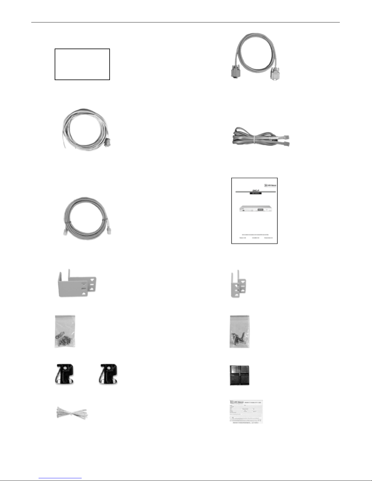
While unpacking the DAC-P, please make sure that all of the following items are included. If some parts are missing, or if
you ever need to order new parts, please refer to the part numbers in parentheses and call DPS Telecom Customer Service a
1-800-622-3314.
DAC-P
(D-PC-932-10A-00)
Page 6
2
E
R
E
H
S
E
O
G
C
I
H
P
A
R
G
DAC-P Data Port to Modem Shelf Cable 6 ft. Download Cable 4 ft.
(D-PR-DACAB-12003.00001) (D-PR-045-10A-04)
DB9 to Open End Cable Telephone Cable 6 ft.
(D-PR-652-10A-06) (D-PR-045-10A-01)
Ethernet Cable DAC-P User Manual
(D-OC-UM032.13200)
23" Rack Ears 19" Rack Ears
Eight 3/8" Ear Screws and Eight Lock Washers Four Rack Screws
Two 1-Amp GMT Fuses Pads
Cable Ties Warranty Card
Page 7

Specifications3
k
–
k
Dimensions: 1¾"H x 17"W x 12"D (4.45 cm x 43.18 cm x 30.48 cm)
Weight: 4 lbs. 3 oz. (1.9 kg)
Mounting: 19" or 23" rac
3
Power Input:
Current Draw: 200mA
Fuse: 1 Amp GMT
Interfaces: 4 DB9 RS-232 serial ports
Operating Temperature: 32°–140° F (0°–60° C)
Operating Humdity: 0%–95% noncondensing
48 VDC
4 DB9 RS-485 TABS ports
1 RJ45 10baseT Ethernet port
1 RJ11 POTS jac
1 DB9 craft port
Operation4
The DAC-P communicates with its alarm collection remotes through dial-up connection. The DAC-P has four DB9 RS-232
serial ports for connecting to up to four modems and four phone lines. The dial-up connection between the DAC-P and its
remotes is two-way; either the DAC-P can initiate a call to poll a remote, or a remote can initiate a call to report an alarm.
The remote will call the DAC-P if:
• Any alarm occurs. (All alarm events are considered equally severe.)
The DAC-P will call the remote if:
• The alive/full update time expires without a call from the remote. The default alive/full update time is 24 hours. The DACP will reset the alive/full update clock if the remote calls to report an alarm.
• The DAC-P receives a control relay command for the remote unit.
• The DAC-P receives a dial command for the remote unit.
• The DAC-P receives a reboot command for the remote unit.
• A DAC-P user chooses the Dial RTU or Reboot RTU command from the terminal interface.
Page 8
4
t
b
b
Remoteswillcallinto
report alarms and give
status reports at userspecified intervals.
Since the station address may be
unknown, the DAC-P will ascertain
the unit's ID by sending a command
to address 0.
This requires that the
station address is listed in
the configuration file.
Remote
Calls DAC-P
Map Data to
MEFA Display Grid
Collect Data
DAC-P Calls
Remote
Acknowledge
All Alarms
The DAC-P will call if the
remote does not report at
the specified time or if a
control is to be sent to the
unit.
The DAC-P signals to the
remote that COS alarms
have been collected.
The remote's configuration
is verified and updated
every time the DAC-P
communicates with it.
Configure
Remote
Send Pending
Control Commands
Control commands are queed
until they can be send. The
command is cancelled if
invalid or if the dial-up
connection cannot be made.
Report Data
Disconnect
To NTP
When Polled
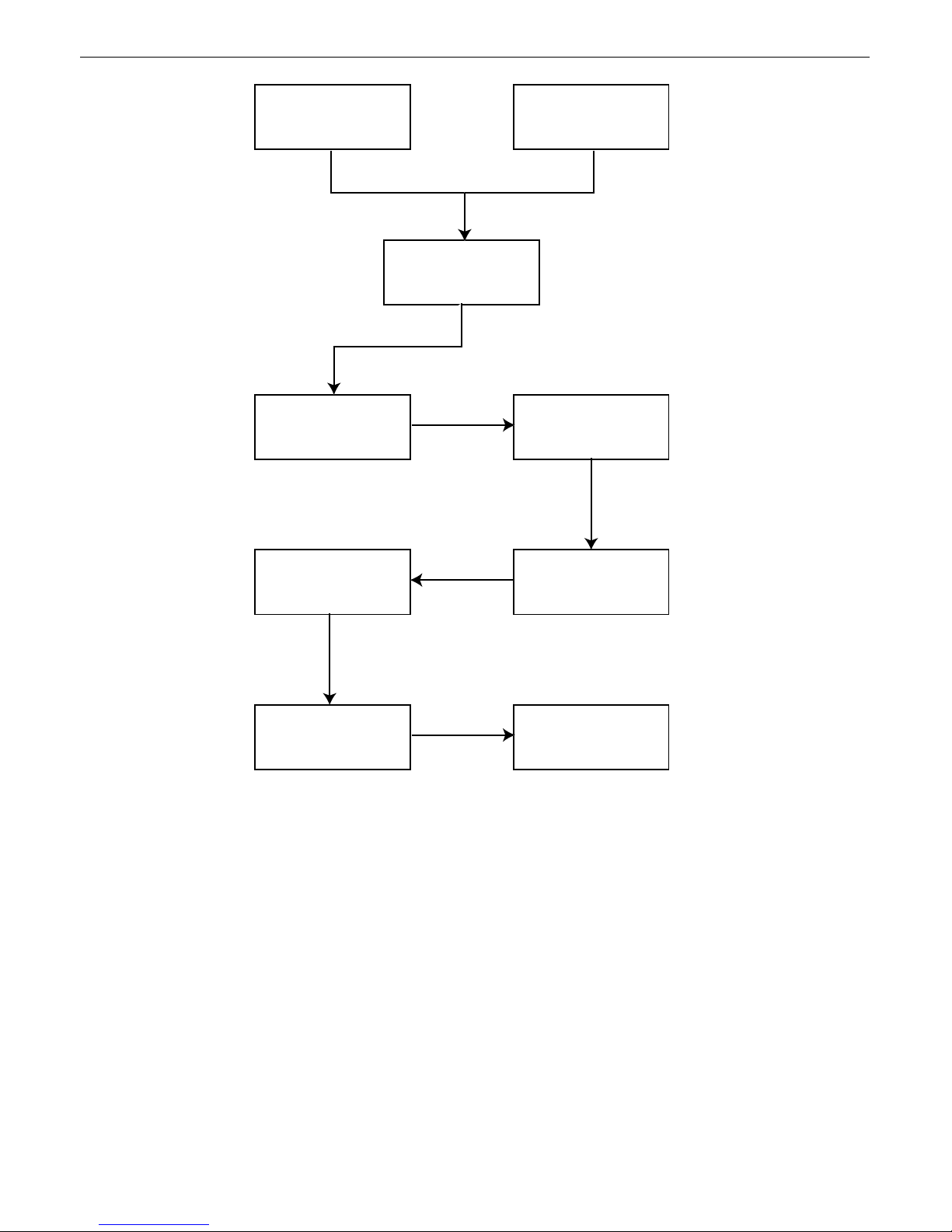
Fig. 2. DAC-P Operations Flow Char
The DAC-P performs a defined set of operations every time it communicates with a remote (see Figure 2):
1. Send FUDR, or full update command to station address 0.
a. Use response to ascertain actual remote address.
. Post alarm data to MEFA displays.
2. Send DACK command to acknowledge collection.
3. If the remote has sent a power-up alarm, send TIME command and restart at Step 1.
4. Download configuration settings (whenever the DAC-P communicates with a remote, it updates the remote's configuration
with the settings in the DAC-P's own configuration file, which is derived from the TMAS database):
a. Download alive/full update time.
. Set momentary relay period to 600 msec standard.
c. Configure all alarms as major.
Page 9
d. Set initial redial time. (There is one global setting for all remotes that report to the DAC-P. Range: 30 seconds to 5
minutes.)
e. Set fallback redial time. (Must be the same as initial redial time.)
f. Set redial attempts before fallback to three attempts.
g. Set primary phone number.
h. Set backup phone number.
i. Set all other phone number fields to none.
5. Send pending relay control commands.
6. If reboot requested, send reboot command.
7. Disconnect.
Installation5
5
Tools Needed5.1
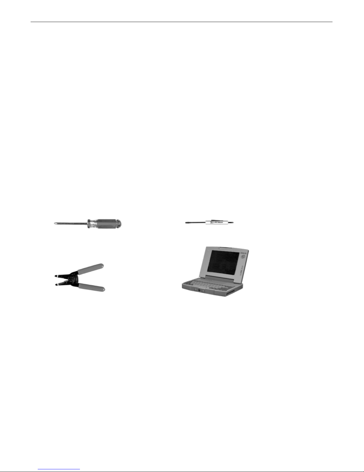
To install the DAC-P, you'll need the following tools:
Phillips Screwdriver Small Standard No. 2 Screwdriver
Wire Strippers/Cutter Computer
Page 10
6
r
Mounting5.2
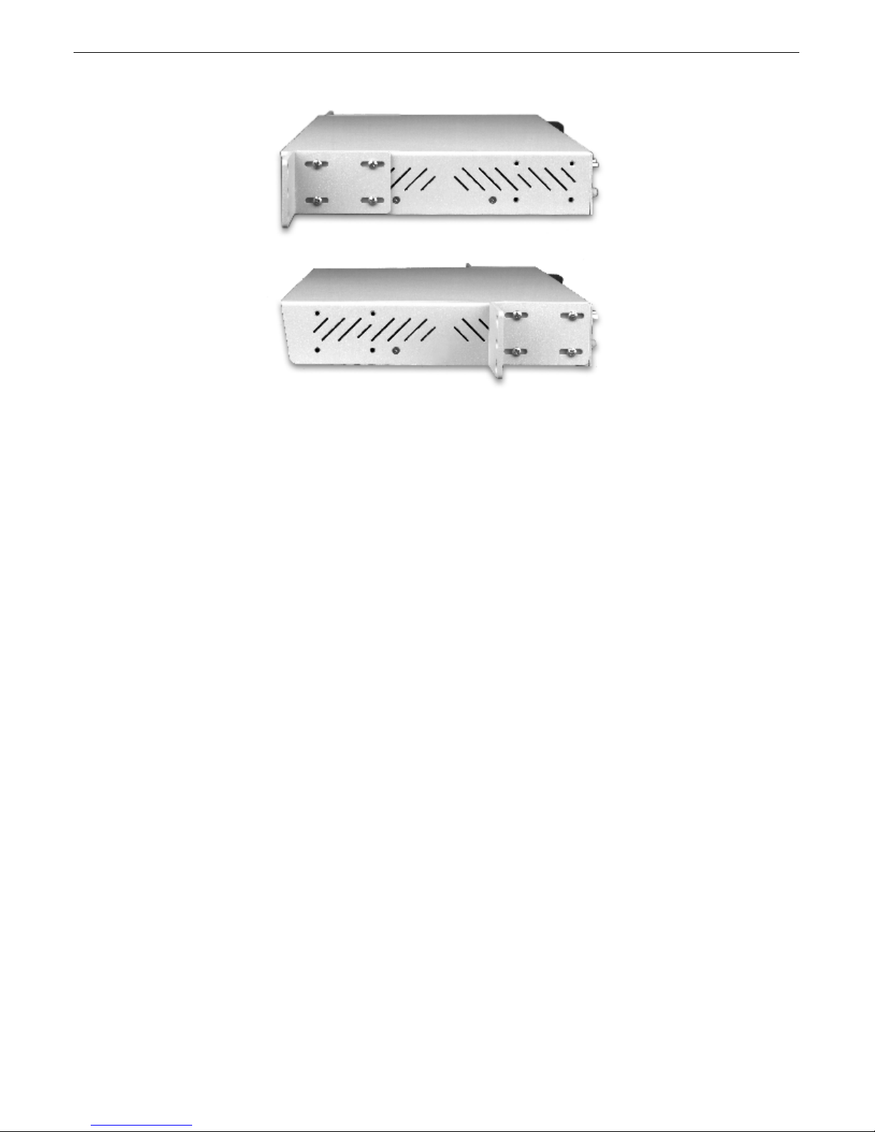
Fig. 3. The DAC-P can be flush or rear-mounted.
The DAC-P can be mounted in a 19" rack or a 23" rack by using different rack ears for each size. Two rack ear locations are
provided. Attach the appropriate rack ears in the flush-mount or rear-mount locations shown in Figure 3.
Power Connection5.3
To connect the DAC-P to a power source, follow these steps:
1. Remove the fuse from the front panel of the DAC-P and make sure that the power supply to the unit is off.
2. Remove the screw lug barrier plug from the front panel of the DAC-P.
3. Connect a -48 VDC line to the -48V terminal and a battery ground to the GND terminal of the screw lug. Seat the barrier
screws firmly, but be careful not to nick the bare wire. Repeat for power source B if you have dual power inputs.
4. Push the plug firmly back into its socket. Note that this connection is keyed and the plug must be properly aligned within
the socket.
5. For earth/frame grounding, connect a copper wire with a ring terminal to the grounding post located on the back panel of
the DAC-P. DPS Telecom recommends wire of at least 14 gauge. Place the ring terminal between the two nuts and secure the
nuts on the grounding post. Connect the other end of the wire to an earth/frame ground.
6. With the DAC-P fuse still removed, turn on the power supply.
7. Connect the black common lead of a voltmeter to the GND terminal and the red lead to the –48V terminal. The voltmete
should read between –43 and –53 VDC. If the reading is outside this range, check your power supply.
8. Do not power the unit until all connections have been made.
9. Insert the fuse to power the DAC-P.
Page 11
7
Network Connections5.4
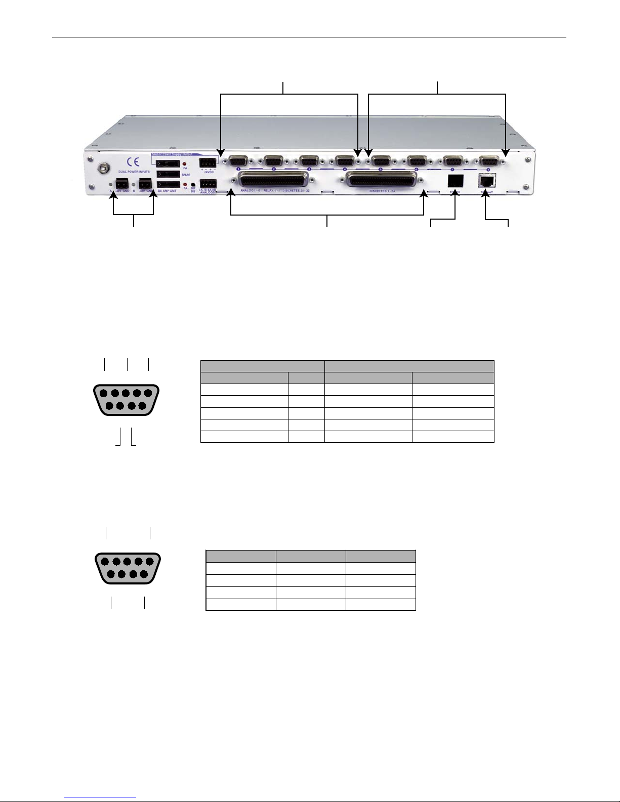
4 RS-232 ports connect to modems 4 RS-485 TABS ports to NTP
Dual Power Feeds
These connections are not used
RJ11 Jack
RJ45 Ethernet Jack
Fig. 4. The back panel of the DAC-P
All network connections for the DAC-P are on the back panel of the unit, as shown in Figure 4.
A RJ45 10BaseT Ethernet jack connects the DAC-P to your LAN or WAN.
Data ports 1–4 are allocated to modem connections. Using the provided cable, connect these ports to the DPS Telecom DialUp Converter Shelf. Pinouts for data ports 1–4 are shown below in Figure 5.
TXRXGND
DAC-P DB9 212 Dial-Up Converter DB25
12345
6789
DCD DTR
Data ports 5–8 connect the DAC-P's four TABS responders to the Network Telemetry Processor. Pinouts for data ports 5–8
are shown below in Figure 6.
RX +
TX +
Signal Pin Signal Pin
TX 2 RX 2
RX 3 TX 3
GND 5 GND 7
DCD 7 DTR 5
DTR 8 DCD 4
Fig. 5. Pinouts for data ports 1–4
12345
6789
RX –
TX –
Signal Pin Wire Color
TX+ 1 Wht/Blu
RX+ 4 Wht/Org
TX– 6 Blu/Wht
RX– 9 Org/Wht
Fig. 6. Pinouts for data ports 5–8
Page 12
8
t
t
Configuration6
Craft Port6.1
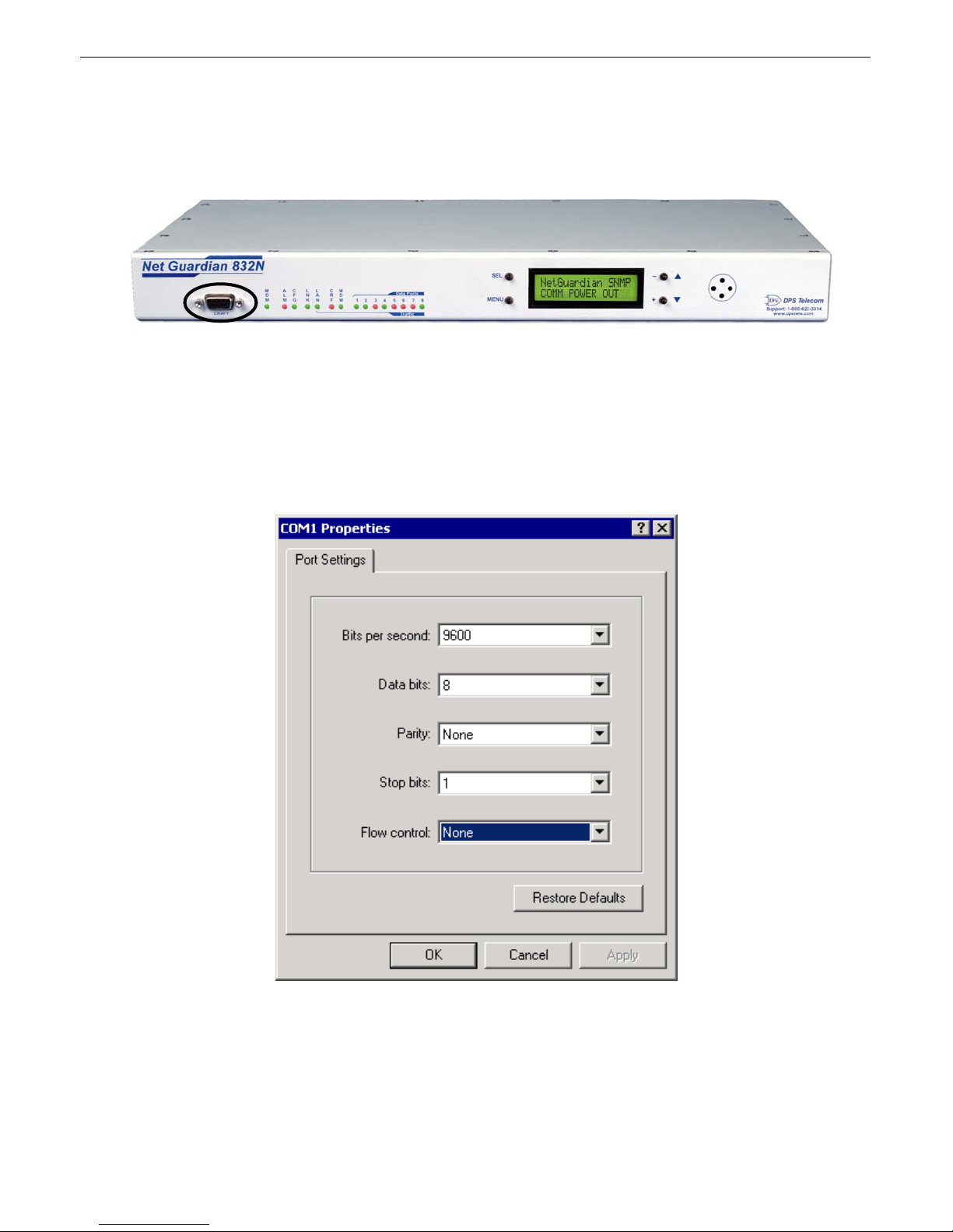
Fig. 7. The DAC-P craft por
The DAC-P can be provisioned and configured either locally, through a craft port connection, or remotely, through a
LAN/WAN connection. However, some initial configuration must be done locally before you can access the DAC-P through
a network connection.
To make a local connection to the DAC-P, connect a DB9 serial cable from the COM port of your computer to the craft por
on the front panel of the DAC-P.
Select the following COM port options, as shown in Figure 8:
• Bits per second: 9600
• Data bits: 8
Fig. 8. Port settings to connect to the DAC-P
Page 13
• Parity: None
N
• Stop bits: 1
• Flow control: None
Terminal Interface6.2
9
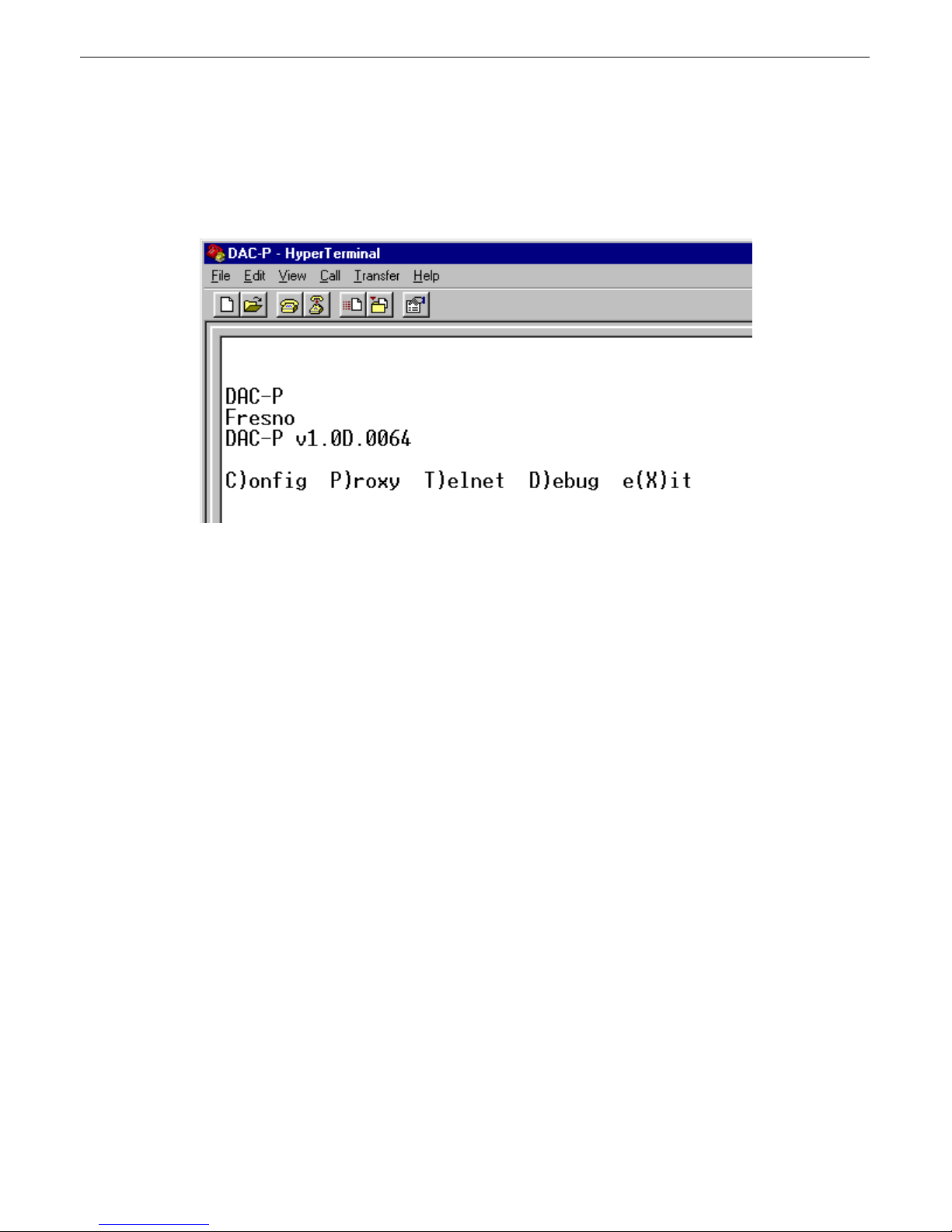
Fig. 9. DAC-P configuration main menu
When you first connect to the DAC-P, all you will see on your screen is a cursor. The Quiet logon feature, which suppresses
the password prompt and the asterisks normally seen when typing passwords, is enabled by default. If you would like to see
a password prompt when connecting to the DAC-P, disable the Quiet logon feature. For instructions on disabling Quiet
logon, see Section 6.6.1, "Logon."
You must enter the password to continue. The factory default password is "dpstelecom," all in lower case. You can change
the password later. Type the password (no asterisks will be displayed if Quiet logon is enabled) and press Enter.
After entering the password, you will see the DAC-P configuration main menu, as shown in Figure 8.
To choose a command, press the key for the letter before or within the parenthesis. For example, to select the C)onfig menu
from the main menu, press C. To e(X)it the terminal interface, press X.
To quit a menu, press Esc, and you will return to the previous menu.
For configuration changes to take effect, you must save your changes in the DAC-P's memory. To save changes, press Esc to
return to the main menu. A confirmation prompt will ask if you want to save changes. Alternatively, you can save your
changes by choosing C)onfig > E)dit > n(V)ram > W)rite. (For more information about writing to NVRAM, see Section
6.6.6, "NVRAM."
ote: If you are using a Unix Telnet client to access the DAC-P, make sure your terminal software is set for character mode.
Many Unix clients are set by default to line mode, which is incompatible with the DAC-P terminal interface. To set your
Telnet client for character mode, press the Esc key to enter command mode and type "mode char." For more information,
consult the man page for your Telnet client.
Page 14
10
Assigning an IP Address6.3
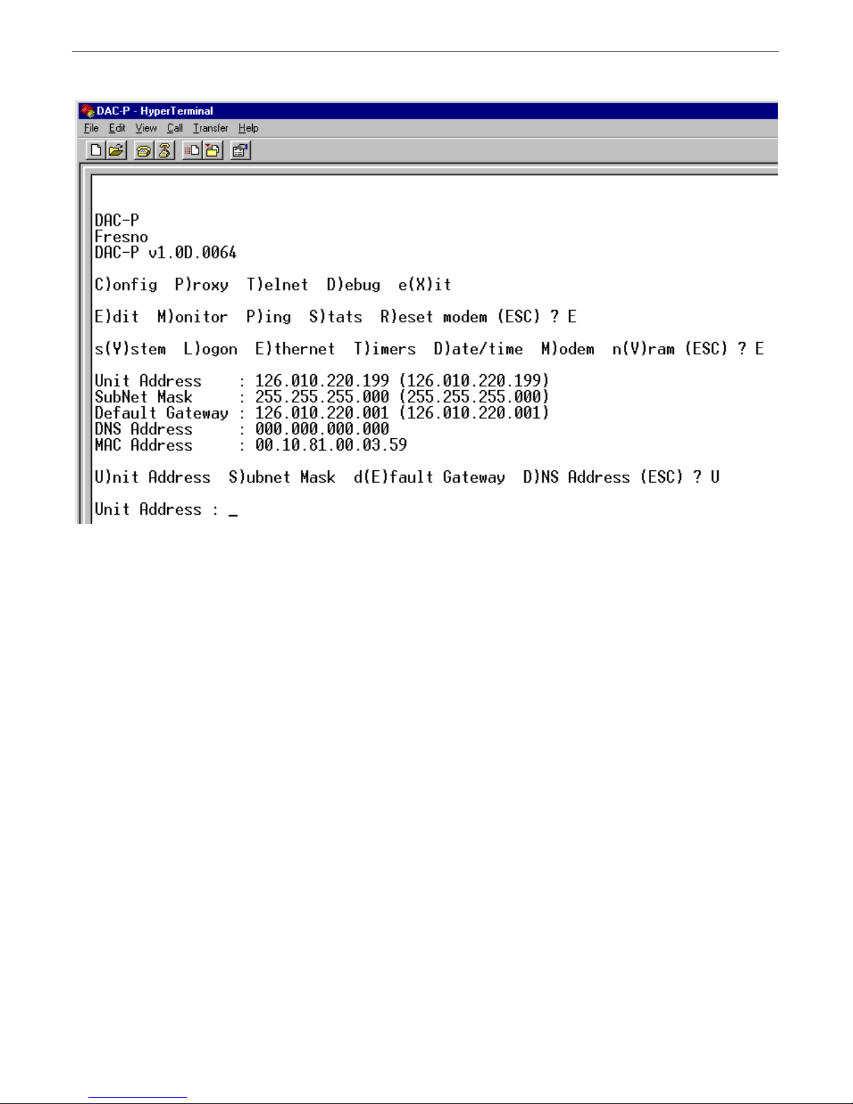
Fig. 10. Assigning an IP address.
Your first step in configuring the DAC-P is to assign it an IP address, so that the unit will appear on your network. The IP
address must be unique—no other device on the network should have the same address.
Connect your computer to the craft port of the DAC-P and begin a terminal session. (See Section 6.1, "Craft Port," for
instructions.)
Choose C)onfig > E)dit > E)thernet. The screen will display the current IP configuration and a menu for editing IP
configuration. (See Figure 10 above.)
You must assign the DAC-P a unit IP address, a subnet mask, and a default gateway. To edit these fields, choose the
appropriate command from the menu. You will be prompted to type a value, as shown in Figure 9.
After making your selections, you must reboot the unit for the changes to take effect. Choose C)onfig > E)dit > s(Y)stem >
R)eboot > y)es.
To verify the DAC-P's IP configuration, ping the IP address you assigned the unit.
Page 15
Configuration File6.4
t
N
t
t
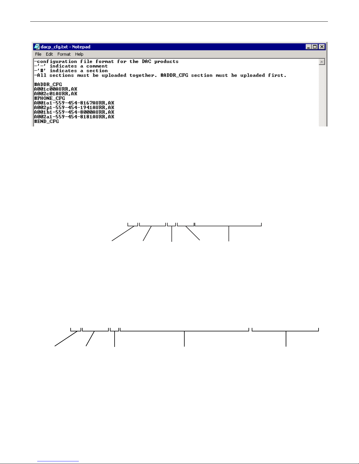
Fig. 11. A sample configuration file
The DAC-P must be provisioned with a configuration file that defines the remotes it will poll. The configuration file is a tex
file derived from the TMAS database using utility software. The file is transmitted to the DAC-P via File Transfer Protocol
(FTP).
ote: Every time a configuration file is uploaded to the DAC-P, the unit's memory is completely overwritten. You mus
always upload a complete configuration file. If a section of the configuration file is omitted, the default settings for tha
section will be used.
11
A sample configuration file is shown in Figure 10. The file is divided into two sections: #ADDR_CFG and #PHONE_CFG.
A001c00AURR,AK
IRIS Port DCP Address
(1–255)
Fig. 12. Elements of an #ADDR_CFG entry
The #ADDR_CFG section defines which remotes the DAC-P will poll, what type of device the remote is, and to which
MEFA to map the device. Valid entries for the address field are 0 to 255. Valid entries for the device type field are: "a" for
DS5000 (single); "b" for DS5000 (dual); and "c" for DS3000 or KDA-E2A. Valid entries for the MEFA field are 0 to 31.
Each line of the #ADDR_CFG section defines an individual remote. Each remote must have a unique address and MEFA.
Device Type
MEFA
(0–31)
Location
(Free-form
text field)
A001o1-559-454-8167AURR,AK
IRIS Port DCP Address
(1–255)
Outbound,
Primary
or Backup
Phone Number
Fig. 13. Elements of a #PHONE_CFG entry
Phone Number
Location
(Free-form
text field)
The #PHONE_CFG section defines the phone numbers associated with remotes. Each line of the #PHONE_CFG section lists
the address of the remote, the type of phone number, and the phone number.
Each remote can have three phone numbers:
1. "o": Outbound phone number. The phone number the DAC-P will dial to call the remote.
Page 16
12
N
r
t
2. "p": Primary phone number. The first number the remote will call to report an alarm. This phone number will be
downloaded to the remote.
3. "b": Backup phone number. The phone number the remote will call to report an alarm if the primary phone number fails.
This phone number will be downloaded to the remote.
If a type of phone number is not defined, no phone number for that function will be assigned. For example, for these lines of
the #PHONE_CFG section:
A001o1-559-454-8167AURR,AK
A001p1-559-454-1941AURR,AK
A002o1-559-454-8181AURR,AK
o line of the configuration file begins "A001b . . .", and therefore the remote at address 1 has an outbound phone numbe
and a primary phone number, but no backup number.
The tag "#END_CFG" signals the end of the configuration file. This tag should appear only once, at the end of the file. No
sections should appear below this tag. Do not put this tag between sections.
Uploading the Configuration File6.5
The configuration file must be uploaded to the DAC-P via File Transfer Protocol. No username is required, but you mus
give a password. The factory default password is "dpstelecom." Any FTP client may be used to transfer the configuration
file, but only a limited set of FTP commands are supported.
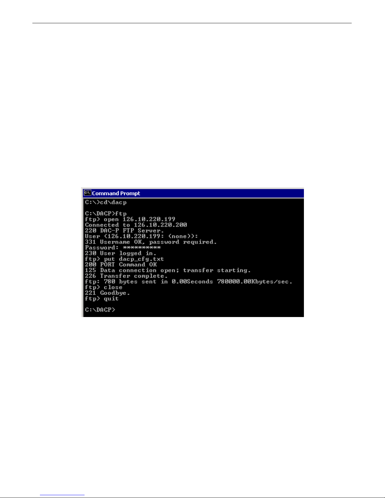
To transfer the file from a DOS prompt, follow these steps (see Figure 14 above):
1. From the DOS prompt, change to the directory where the configuration file is located.
2. Type "ftp" and press Enter.
3. At the FTP prompt, type "Open" and the IP address of the DAC-P, and press Enter.
4. Type the password (factory default is "dpstelecom") and press Enter.
5. Type "put" and the name of the configuration file and press Enter. (If thve configuration file is in a different directory you
must type the full path name.
6. Type "close" and; press Enter to close the connection to the DAC-P.]
Fig. 14. Uploading the configuration file
Page 17
7. Type "quit" to exit FTP.
If the configuration file is not correctly formatted, you will see a STOR error message, which will state that the data could
not be stored. If you see a STOR error, verify the formatting of the configuration file and upload again. (For information on
configuration file formatting, see Section 6.4, "Configuration File."
After uploading, the DAC-P must be rebooted for the new configuration to take effect.
There are four ways you can reboot the DAC-P:
1. Type "REBOOT" at the FTP password prompt.
2. In the DAC-P terminal interface, choose C)onfig > E)dit > s(Y)stem > R)eboot. (See Section 6.6.1).
3. Cycle power to the DAC-P unit.
4. Select the Reboot command from the LCD display menu. (See Section 9).
Other Configuration Options6.6
More configuration options are available through the DAC-P's terminal interface. To select these options, start a terminal
session with the DAC-P, either locally through the craft port or remotely via Telnet.
13
6.6.1 System
Fig. 15. System menu commands
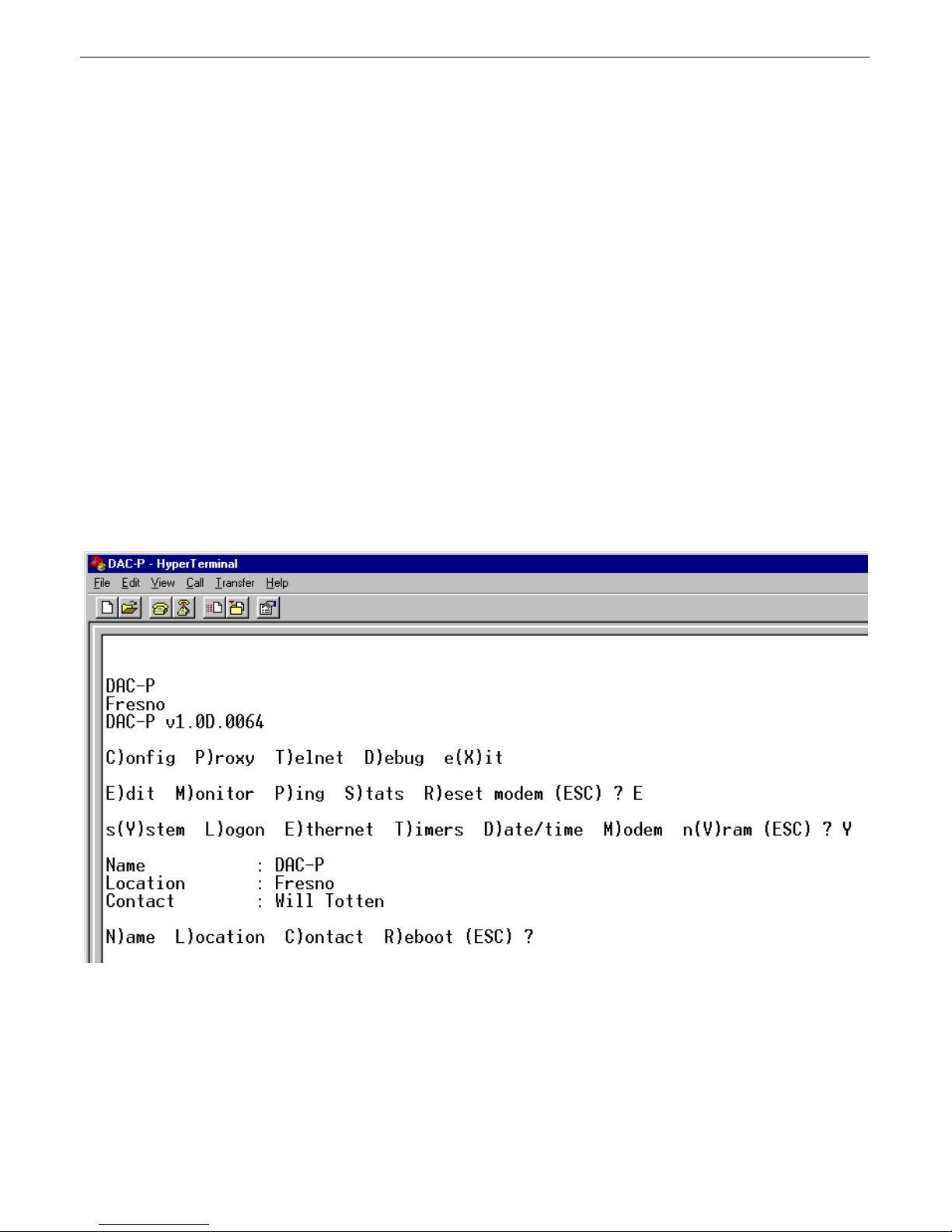
To edit identification information for the DAC-P, choose C)onfig > E)dit > s(Y)stem.
The System menu contains commands for editing the name of the DAC-P unit, its location, and the primary contact person
responsible for the unit.
The C)onfig > E)dit > s(Y)stem > R)eboot command reboots the DAC-P. If you choose the R)eboot command, a
confirmation prompt will ask you to confirm your choice.
Page 18
14
6.6.2 Logon
Fig. 16. Editing the Master Password
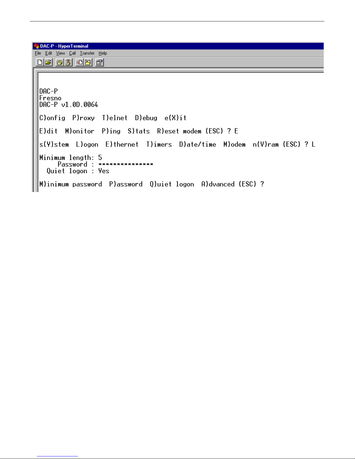
To edit passwords and define security levels for users, choose C)onfig > E)dit > L)ogon.
The first three commands on the Logon menu define options for the Master Password. The Master Password has all access
rights. There is no user name associated with the Master Password.
The options for editing the Master Password are: minimum length of the password, the password itself, and the Quiet logon
option.
If you choose to change the Master Password, you will be prompted to type the new password once to enter and a second
time to confirm. If both entries are the same, the screen will display "Password change successful."
When enabled, Quiet logon disables the password prompt and the asterisks that normally appear when the password is typed.
For increased security, the default setting is Quiet logon Yes. The Q)uiet logon command is a toggle command; pressing the
Q key will switch between Quiet logon Yes and Quiet logon No.
Page 19
15
t
t
Fig. 17. Authorized user lis
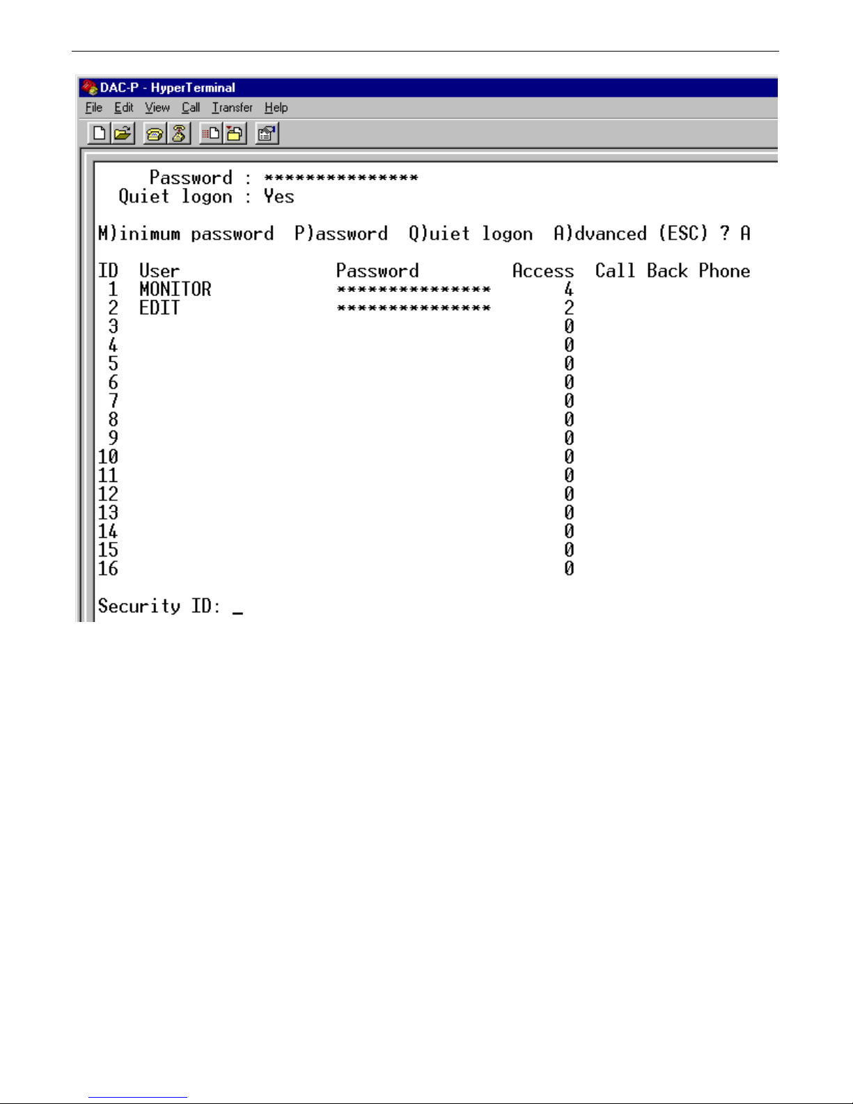
To set passwords and security levels for users who do not have access to the Master Password, choose C)onfig > E)dit >
L)ogon > A)dvanced.
Up to 16 users can be defined, and each can have unique access rights. In the example in Figure 17, the user MONITOR is
authorized only to access the monitor screens, while the user EDIT can only edit the configuration database. To create or edi
a user, type is or her ID number and press Enter.
Page 20
16
Fig. 18. Editing user security levels.
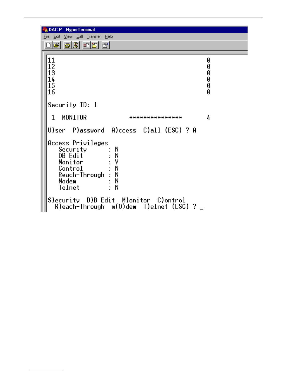
Once you have selected a user, you can define the user's name, password, and access. If you choose the U)ser or P)assword
commands, you will be prompted to enter the user name or password. User passwords must be entered a second time for
confirmation. If you want to delete a user, choose the U)ser command, erase the user's name, and press Enter. A confirmation
prompt will ask you if you want to delete the user.
Choosing the A)ccess command opens a list defining the user's access privileges, as shown in Figure 18. Choosing one of the
menu commands toggles permission for that item. In the example above, to add database editing access to the user
MONITOR, press D, and the list will update to read "DB Edit: Y." To remove MONITOR's monitoring privileges, press M,
and the list will update to read "Monitor: N."
The S)ecurity command gives the user the privilege to edit passwords, including the Master Password. A user with only DB
Edit privileges cannot edit passwords.
If all access privileges are set to Y, the user has the same access privileges as the Master Password.
Page 21
6.6.3 Timers
17
Fig. 19. Timers menu
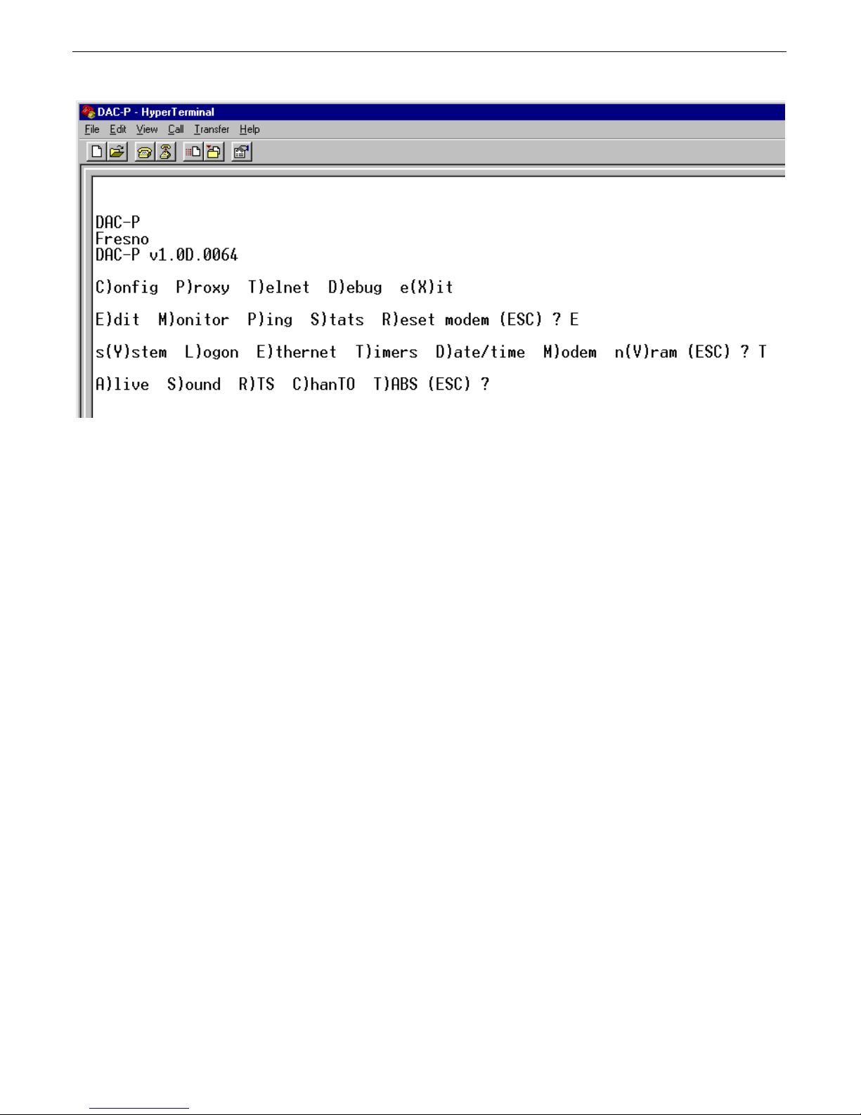
The Timers menu contains commands for editing the alive/full update time, how long the alarm speaker will sound, the RTS
head and tail time, channel timeout, and TABS poll delay.
Page 22
18
To select the Timers menu, choose C)onfig > E)dit > T)imers.
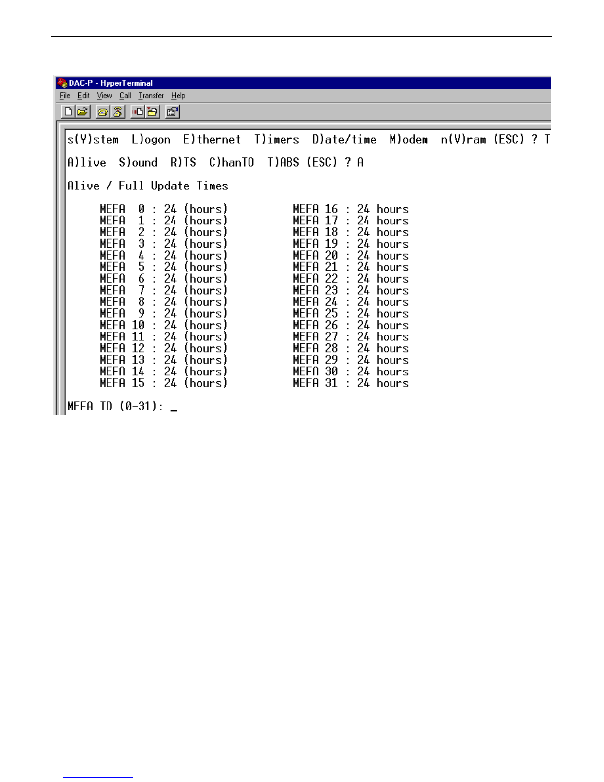
Fig. 20. Editing alive/full update times
The alive/full time determines how often the remote will call the DAC-P to give a status report. If the alive/full update time
expires and the remote has not reported, the DAC-P will call to poll the remote. The alive/full update timer is restarted
everytime the DAC-P communicates with the remote.
To edit alive/full update times, select C)onfig > E)dit > T)imers > A)live. This command opens a list of remotes, listed by
their MEFAs. To select a particular remote's alive/full update time, type its MEFA ID number and press Enter. If the
alive/full update time is set to zero, the alive/full update timer feature is disabled.
The C)onfig > E)dit > T)imers > S)ound command sets how long the speaker will sound if an alarm condition is detected.
Choosing this command will open a menu for setting the sound timer period and time units. To disable the speaker, set the
sound timer to zero.
The C)onfig > E)dit > T)imers > R)TS command opens menu options for setting the RTS Head time (how long the DAC-P
carrier is on before transmitting data) and RTS tail time (how long the carrier is on after transmitting data). The default value
for both times is zero, which sets the DAC-P carrier for always on, or constant carrier.
The C)onfig > E)dit > T)imers > C)hanTO command sets the channel timeout timer. The channel timeout is the maximum
time the RTU has to respond to a poll before the poll is considered failed. Range for channel timeout is 20–5000 msec.
The C)onfig > E)dit > T)imers > T)ABS command sets the TABS poll delay. Range for TABS poll delay is 20–255 sec.
Page 23
6.6.4 Date and Time
19
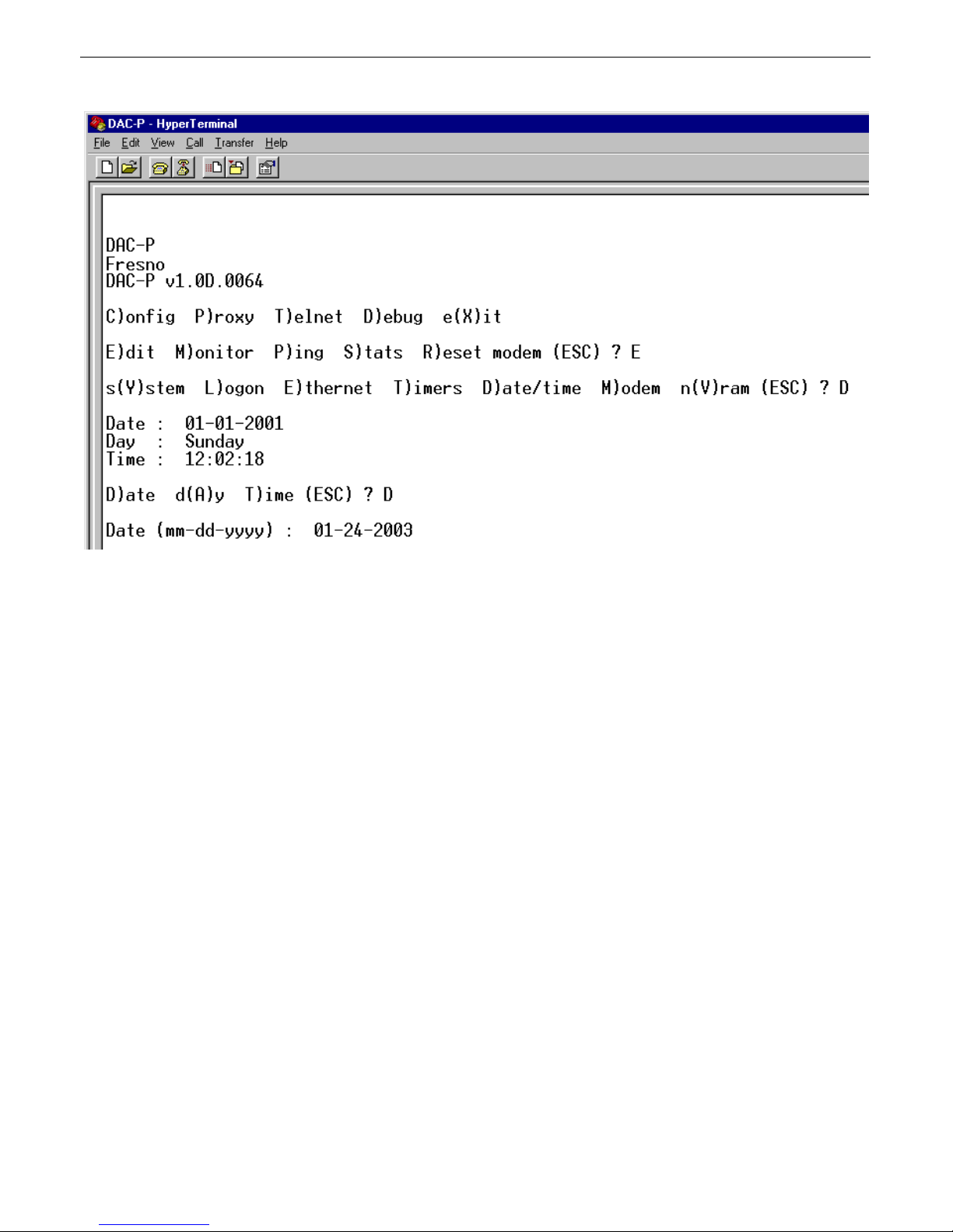
Figure 21. Editing the date
To set the DAC-P's internal clock, choose C)onfig > E)dit > D)ate/time.
The available options are to set the date in MM-DD-YYYY format, the day of the week, and the time. To choose an option
to edit, press the appropriate key and you will be prompted to enter the correct information.
Page 24
20
6.6.5 Modem
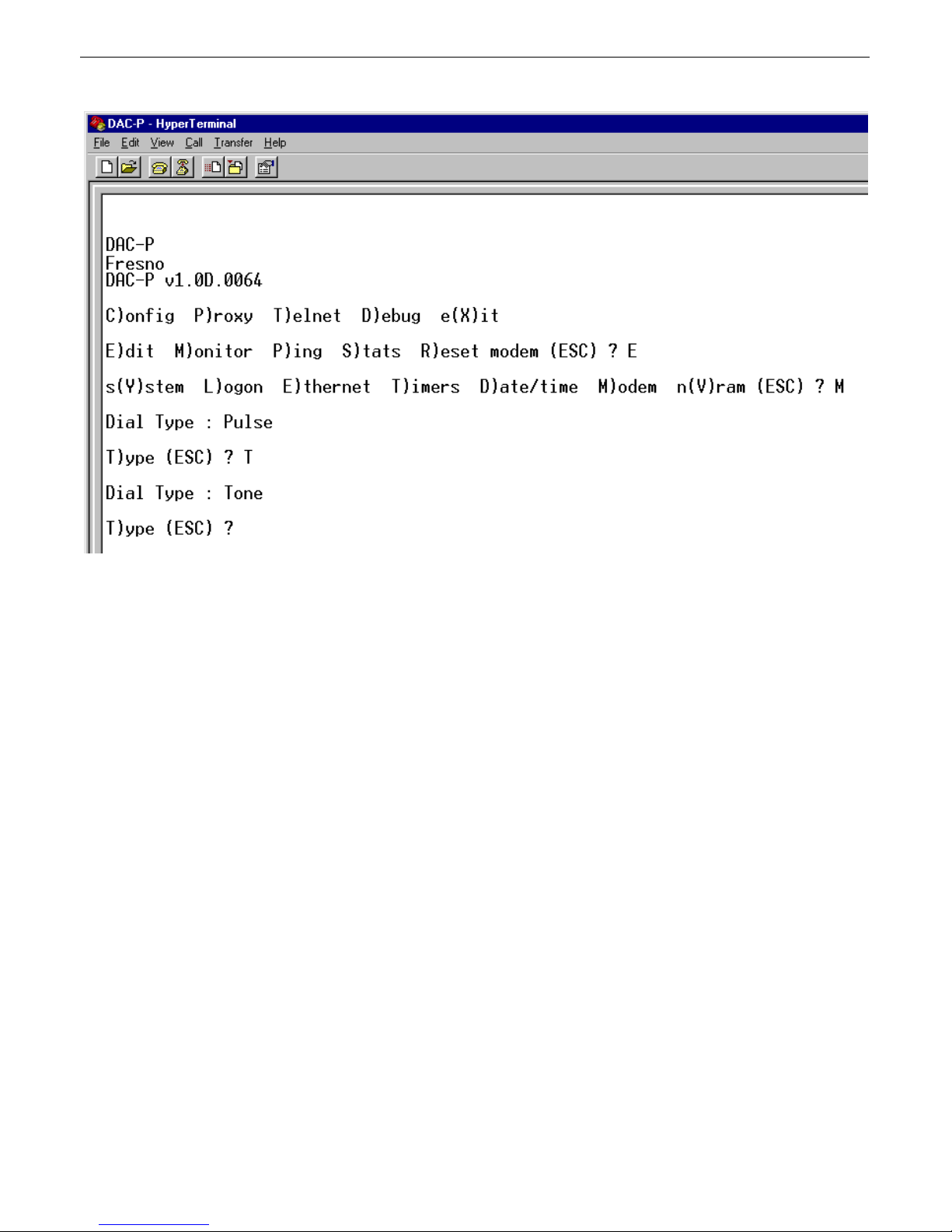
Figure 22. Setting modem for tone dialing
The C)onfig > E)dit > M)odem command provides access to one option, the dial type used by the modem. If you choose the
M)odem command, the DAC-P will report whether the modem is set for pulse or tone dialing. Choosing the T)ype command
will toggle between pulse and tone dialing. Wheneveer applicable, RTUs will be configured to the same dialing type as the
DAC-P.
Page 25
6.6.6 NVRAM
21
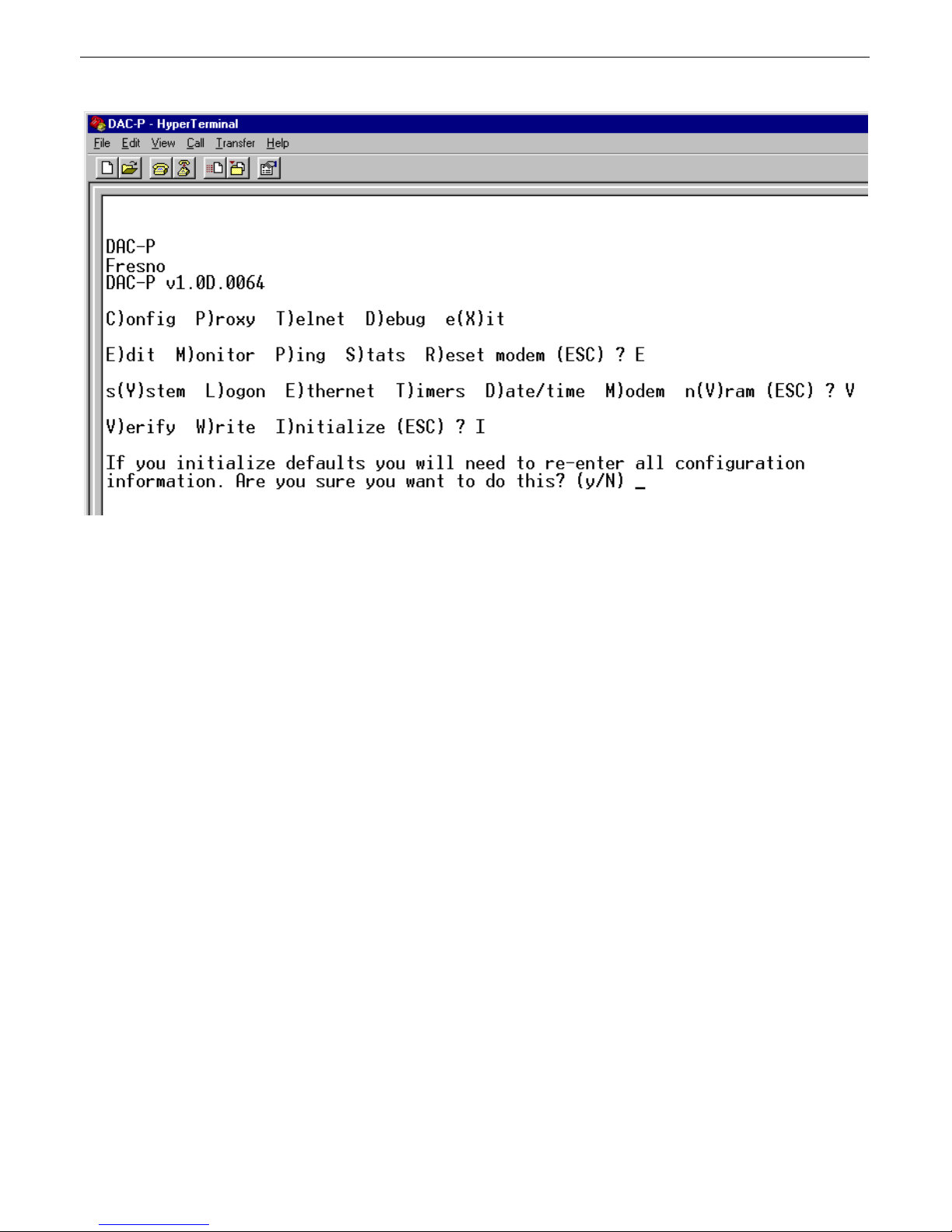
Figure 23. Initializing NVRAM
C)onfig > E)dit > n(V)ram opens a menu of commands for working with the DAC-P's nonvolatile RAM, or NVRAM.
The configuration file and all information entered through the terminal interface are stored in the DAC-P's nonvolatile RAM.
Erasing or overwriting the nonvolatile RAM will alter the DAC-P's configuration.
The NVRAM menu contains three commands:
The V)erify command checks the integrity of the NVRAM.
The W)rite command overwrites the NVRAM with the configuration information defined in the current terminal session. Use
this command to save changes to the DAC-P's configuration.
The I)nitialize command will erase the NVRAM, removing the configuration file and all other configuration information. If
you choose the I)nitialize command, a confirmation prompt will ask you to confirm your choice (see Figure 23).
NOTE: Initializing the NVRAM will erase all configuration information, including the TMAS database configuration
file. Do not initialize the NVRAM unless you want to re-enter all configuration information.
Monitoring7
The terminal interface can also be used to monitor the DAC-P, either remotely through a Telnet session or through a
computer connected to the DAC-P's craft port. The monitoring features of the terminal interface can be used to troubleshoot
problems and verify correct operation of the DAC-P.
Page 26
22
MEFA7.1
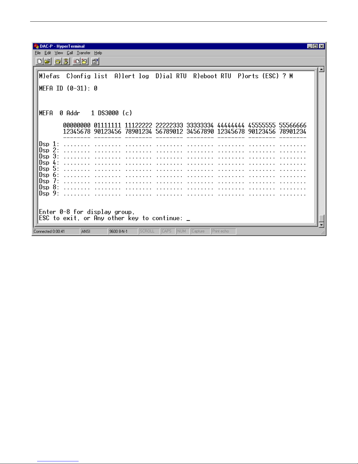
Fig. 24. Monitoring MEFAs
The C)onfig > M)onitor > M)efas command displays the collected data for a for each MEFA in the format in which it will be
reported to the NTP.
If you choose the M)efas command, a prompt will ask you to specify a MEFA (range 0–31). The screen will display the data
for the first nine displays. Enter a number 0–8 to see other display groups. There are 89 displays for each MEFA.
Page 27
23
t
Config List7.2
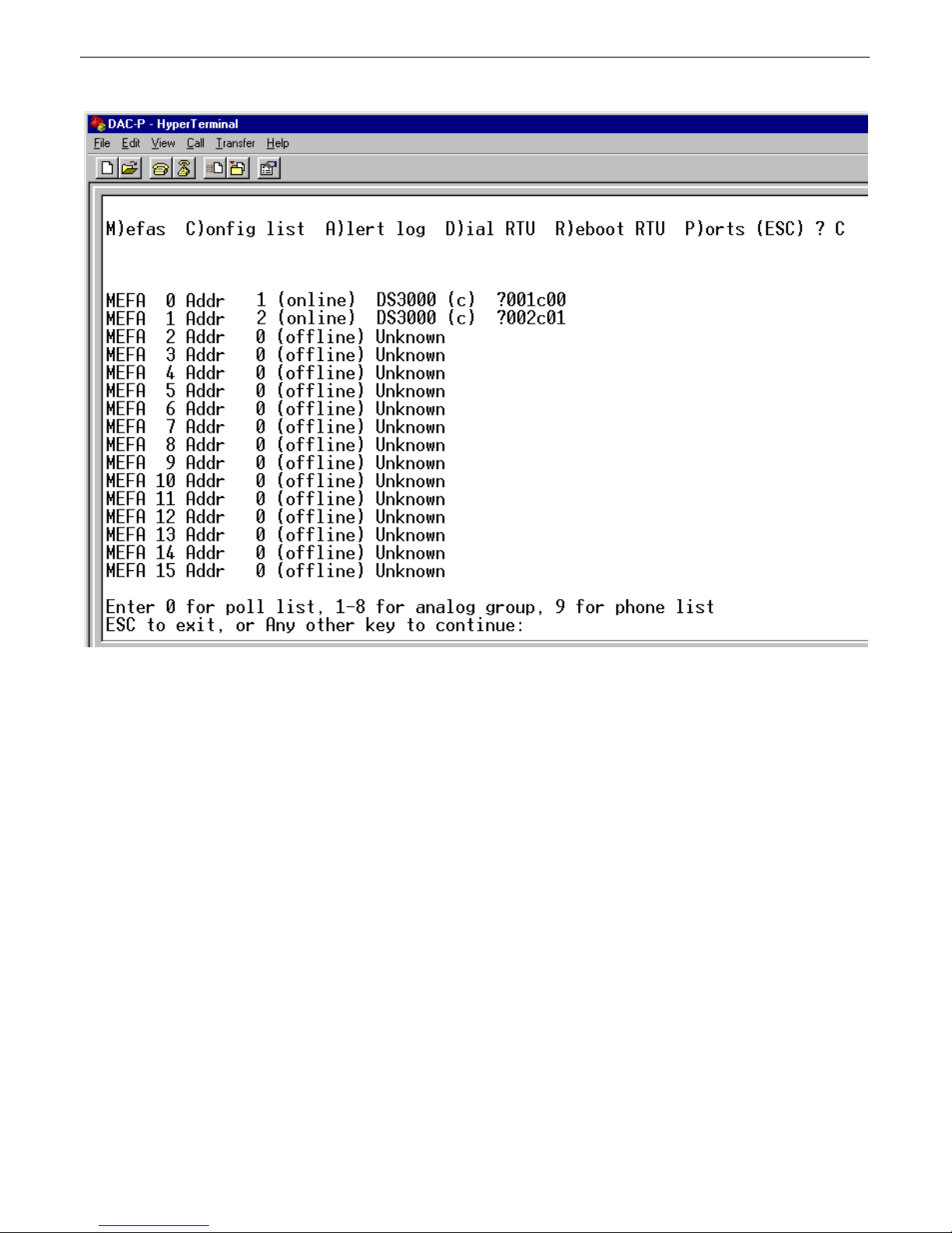
Fig. 25. Poll lis
To review the configuration file currently used by the DAC-P, choose C)onfig > M)onitor > C)onfig list.
The configuration list consists of two sections, the poll list, shown in Figure 25, and the phone list, shown in Figure 26.
The poll list shows the DCP address and remote device associated with each MEFA, and the remote's online status.
Page 28
24
t
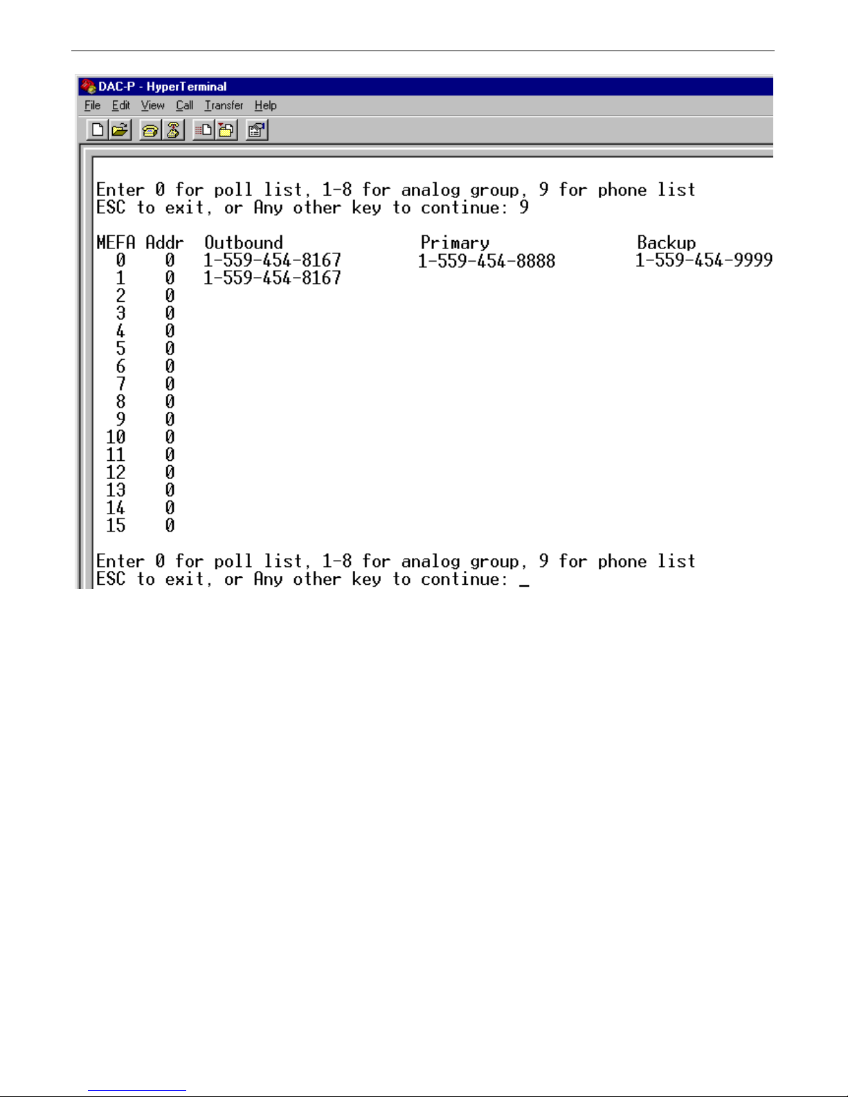
Fig. 26. Phone lis
To see the phone list, press 9. The phone list (Figure 24) displays the phone numbers associated with each MEFA.
To return to the poll list, press 0.
Alert Log7.3
The DAC-P maintains a log of all system alert messages. Reading the alert log can help you detect errors and verify correct
functionality. The alert log is cleared whenever the DAC-P reboots or the user clears it.
To see the alert log, choose C)onfig > M)onitor > A)lert log. Each alert message is stamped with the date and time of the
event. A prompt will ask you if you want to delete the messages in the alert log.
The following two sections explain some common alert messages.
7.3.1 Configuration File Upload Alerts
Here are some alert messages referring to uploading configuration files, and their explanations:
RTU Address Out of Range, addr = X
The remote address was not in the acceptable range of 1–255.
Page 29

Multiple Entries for the Same RTU Address, addr = X
Only one remote can be associated with each MEFA.
Mefa Out of range, mefa = X
The MEFA index is not in the acceptable range of 0–31.
Multiple Entries for the same Mefa, mefa = X
There can be only one configuration entry for each MEFA.
Tech Code Not Recognized, tech = X
Configuration entry does not have correct device type code. Correct codes are "a" (DS5000) or "c" (DS3000).
Type Specifier for Phone Number Not Recognized, type = X
Phone numbers must be prefaced with the correct specifier. Correct specifiers are "o" (outbound number), "p" (primary
number), or "b" (backup number).
RTU Address Does Not Have a Contact Phone Number, addr = X
All configuration file entries for remotes must have at least an outbound phone number.
7.3.2 Remote Communication Alerts
Here are some alert messages referring to communication with alarm collection remotes, and their explanations:
25
Calling RTU Address X from Port X
The DAC-P is calling the indicated remote.
Call to RTU Address X Complete. Disconnecting Port X.
A call is complete. This message appears whether or not the call was successful.
Connection Made to RTU Address X on Port X at 1200 bps.
The DAC-P has connected to the remote at the indicated baud rate.
Failed Multiple Poll Attempts to RTU Address X from Port X.
The call was made, but communication was unsuccessful. The character time-out timer may be too narrow, or the DAC-P
might be connected to a nonworking or incompatible RTU.
Failed to Connect. Could not Call RTU Address X from Port X.
The remote did not answer the DAC-P's call.
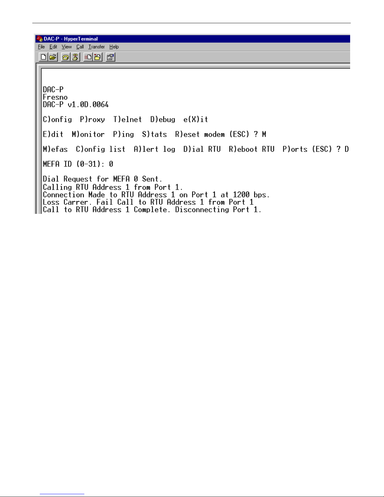
Loss Carrier. Fail Call to RTU Address X from Port X.
The remote's modem has dropped its carrier signal, terminating the connection.
RTU Address X is not Configured. Aborting Connection at Port X.
The detected RTU address does not appear in the DAC-P database. The DAC-P configuration file needs to be reviewed and
updated.
Initializing MEFA Alarm Bitmaps.
The MEFA alarm bitmpas are reinitialized whenever the DAC-P reboots or a new configuration file is uploaded.
Control Queue Full - DS3000 Control Request Discarded.
Multiple relay requests were recieved faster than they could be processed.
Unable to Send Control Command.
Communication was terminated before a relay command could be sent, and the command was discarded.
Unable to Send Reboot Command.
Communication was terminated before a reboot command could be sent, and the command was discarded.
Sending Reboot Command to RTU Address X from Port X.
Page 30
26
A reboot command has been sent to the RTU.
Dial RTU7.4
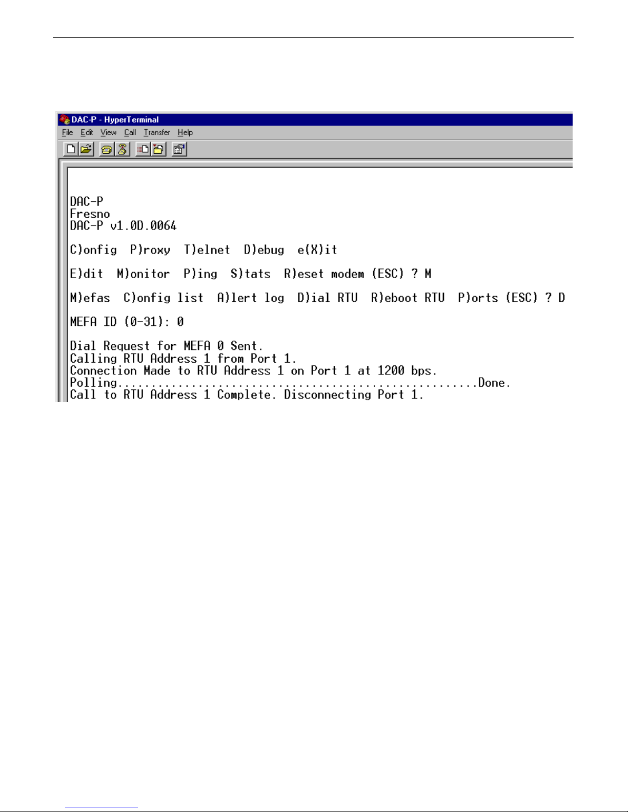
Fig. 27. A successful call to an RTU.
The C)onfig > M)onitor > D)ial RTU command initiates a call to a remote. If you choose this command you will be
prompted to enter the MEFA of the remote you want to call. A successful call will look like Figure 27.
Page 31
27
N
Fig. 28. A failed call to an RTU
If the DAC-P cannot initiate communication with the remote, you will see a screen like Figure 28.
ote: After a call to an RTU has been initiated, pressing the Esc key will exit to the Monitor menu, but it will not cancel the
call, which will proceed even if the call is not monitored.
Page 32
28
N
Reboot RTU7.5
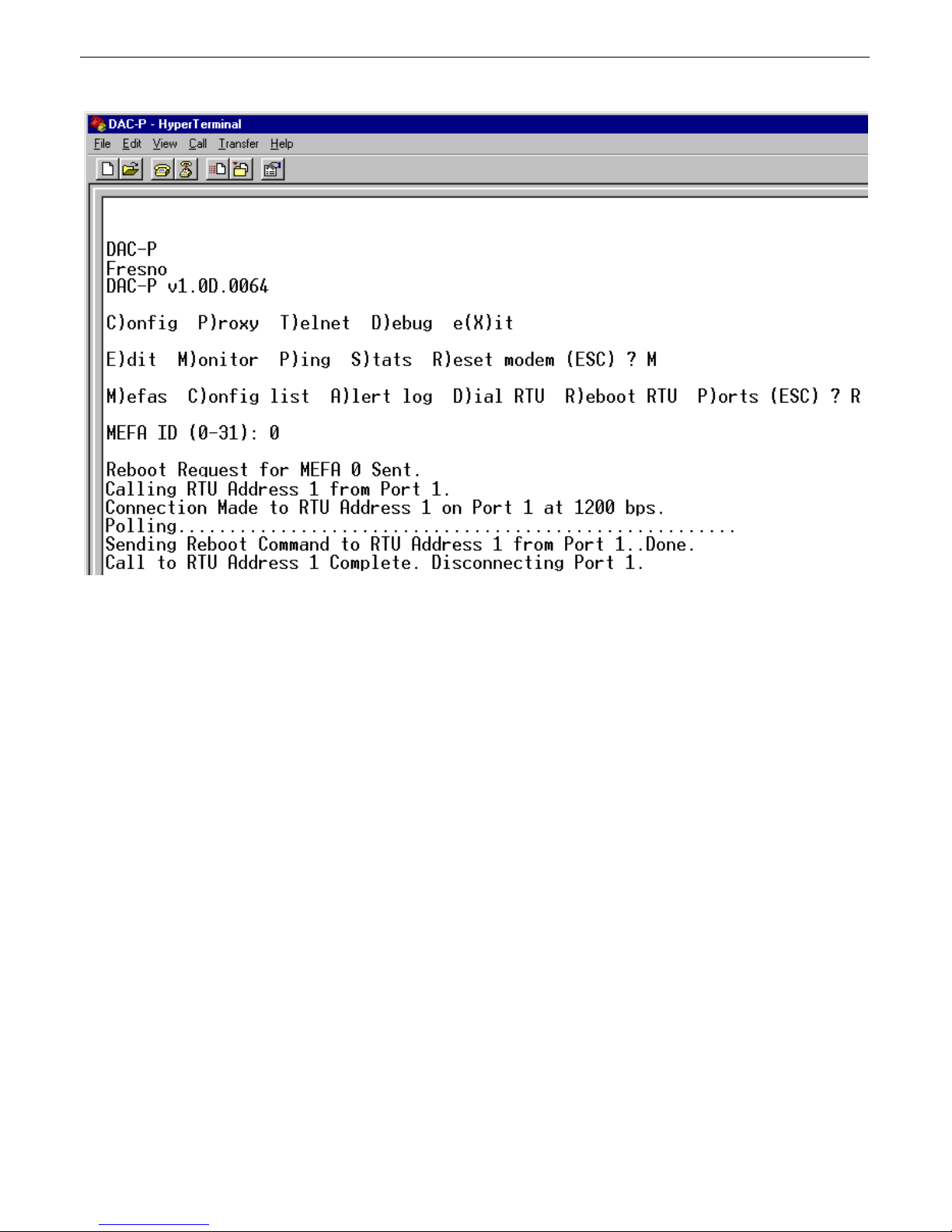
Fig. 29. Rebooting a remote from the DAC-P.
The C)onfig > M)onitor > R)eboot RTU command initiates a call to a remote and sends it a reboot command. If you choose
this command you will be prompted to enter the MEFA of the remote you want to reboot. A successful reboot will look like
Figure 29, above.
ote: After sending a reboot command, pressing the Esc key will exit to the Monitor menu, but it will not cancel the
transmission of the reboot command, which will proceed even if the call is not monitored.
Page 33
29
Other Commands8
Ping8.1
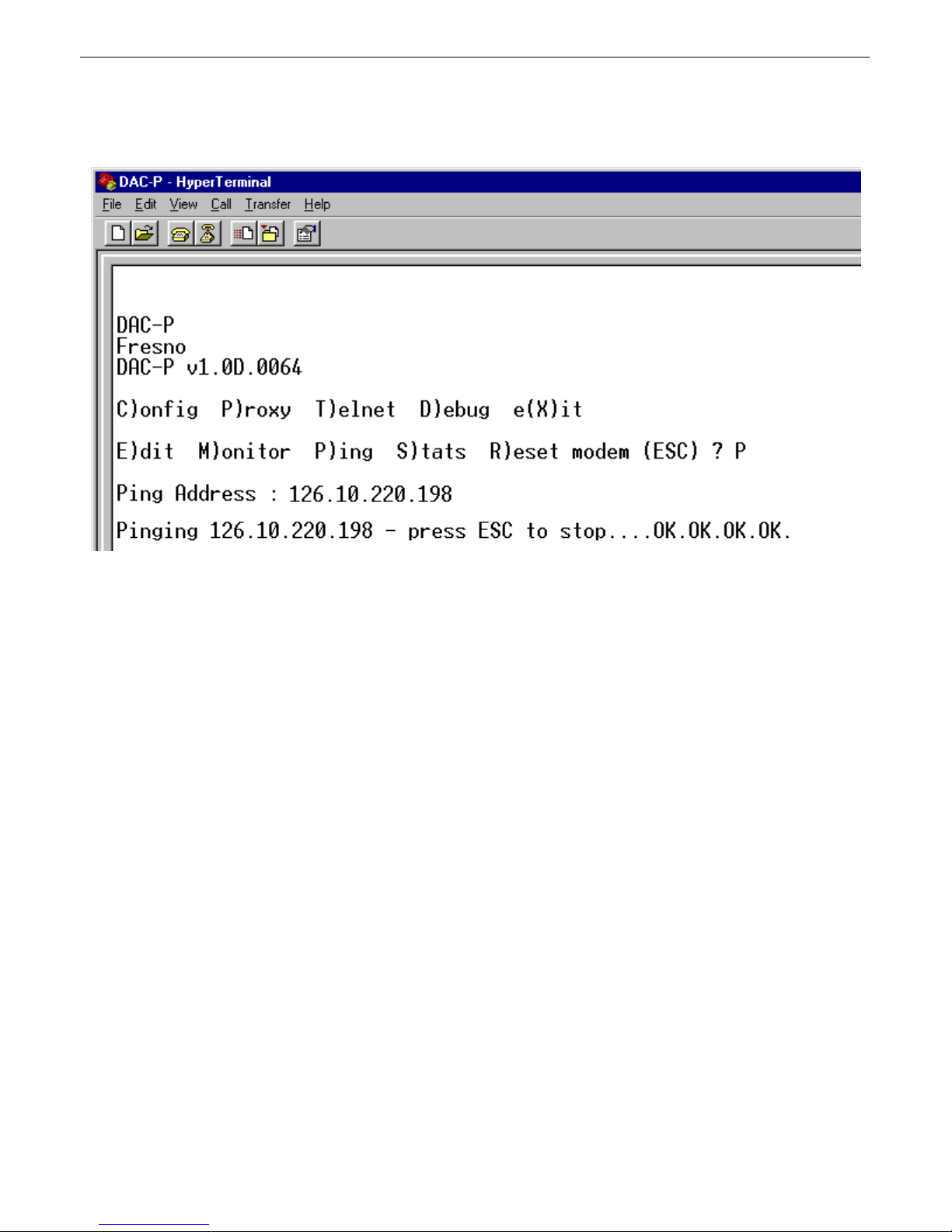
Fig. 30. Ping command
The C)onfig > P)ing command pings IP addresses on your network. If you choose this command, you will be prompted to
enter the IP address you want to ping. A successful ping will look like Figure 30. To stop pinging, press Esc.
Page 34
30
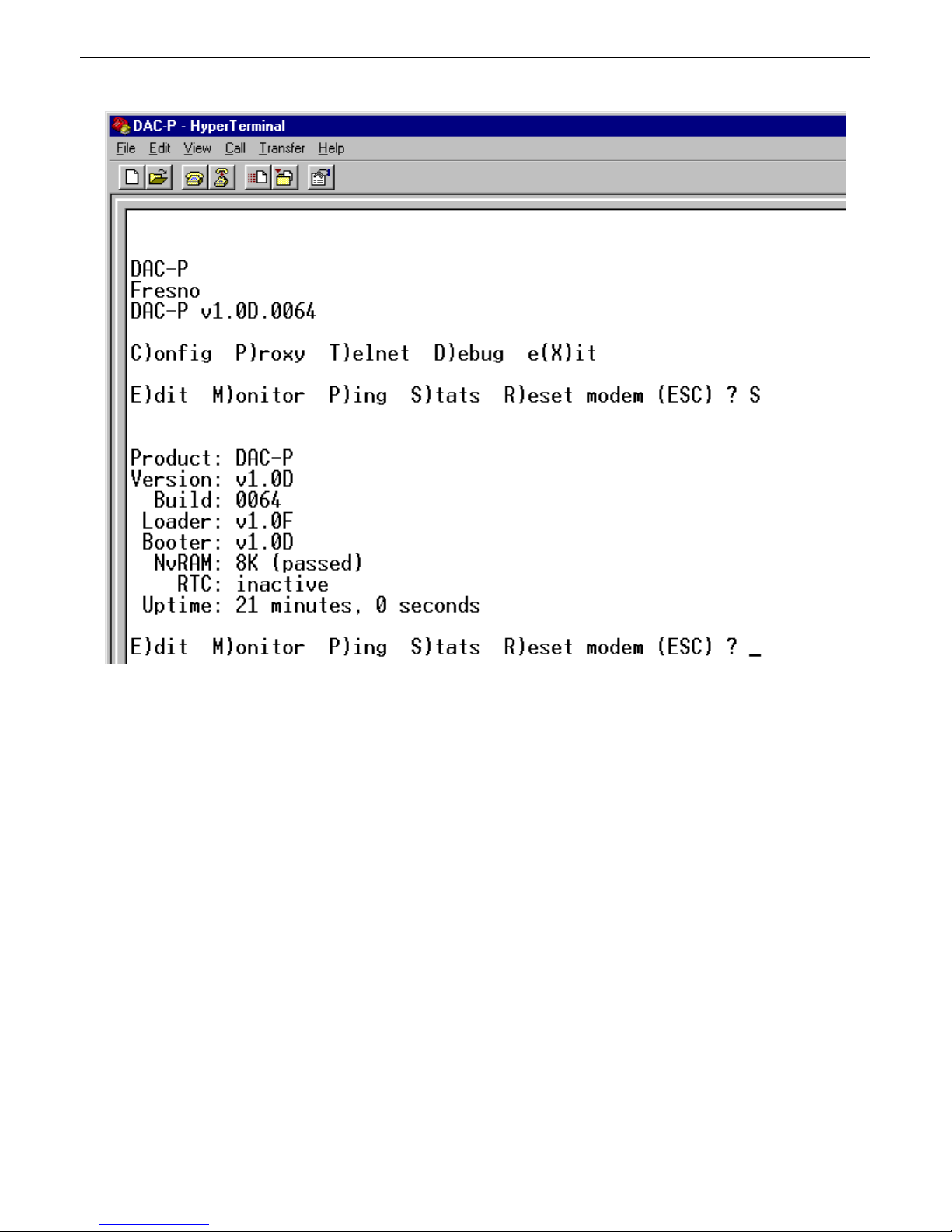
Stats8.2
Fig. 31. Stats command
The C)onfig > S)tats command displays a list of system statistics, as shown in Figure 31.
Page 35
31
Debug8.3
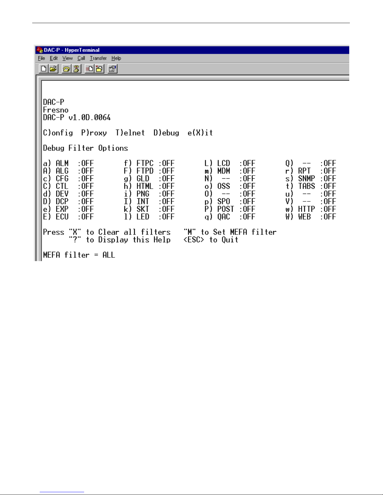
Fig. 332. Debug filters
The D)ebug command displays communications activity between the DAC-P and its remotes as it is processed. There are
seven filters to selectively display communications information.
Choosing the D)ebug command displays the screen shown in Figure 32. To activate a filter, press its command key. To turn
off all filters, press X.
The MEFA filter isolates communication with with remote devices. You can see communication traffic with either one
MEFA or all MEFAs.
The communication filters are:
DCP: Displays DCP communication in English format.
INT: Displays communication in hexadecimal format.
POST: Displays posting of collected alarm data to MEFA bitmaps.
OSS: Displays posting of TABS control commands.
FTPC: Displays processing of FTP connection.
FTBD: Displays processing of FTP data.
TABS: Displays communication on all four TABS channels.
Page 36
32
p
r
Filters other than those listed above are not needed to debug DAC-P communication. These filters should be left off.
It is useful to display several filters together. For example, displaying communications traffic through the DCP, INT, and
POST filters gives you a view of DCP communications between the DAC-P and the remotes, the DCP communication in
hexadecimal format, and how the data is posted to the MEFA bitmaps.
Unused Commands8.4
The commands P)roxy, T)elnet, and C)onfig > R)eset modem are not used with the DAC-P.
LCD Display and Menu9
Using the LCD display menu
The four buttons surrounding the front panel LCD display are used to access the LCD display menu. To access the menu,
ress the MENU button. To scroll the menu, use the + and – buttons. To select a menu command, press the SEL button.
Standard Prompt
When no menu item is selected, the LCD panel will display the firmware version and the standard prompt, "Press MENU fo
front panel operations."
Controlling Display Speed
The scroll speed can be temporarily increased by pressing and holding the + button while the message is active.
Menu Commands:
• Reboot: Reboots the DAC-P.
• Run Config: Forces the configurator to run on the craft port at 9600, N, 8, 1.
Front Panel LED Operation10
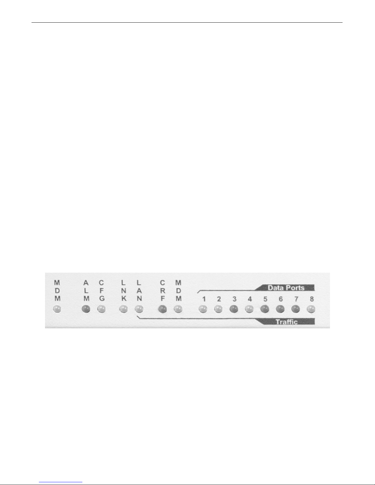
Fig. 33. Front panel LEDs
The LEDs on the front panel of the DAC-P display alarm and communication status. Table A shows the meaning of the LED
display messages.
Page 37

LED Status Description
Flashing Red New alarm status ALM
Solid Red Standing alarm acknowledged
CFG
Flashing Red NVRAM not verified (download
needed)
Flashing Green NVRAM verified, system
operational
Green Ethernet link OK LNK
Red Ethernet link failure
Flashing Green Data transmit LAN, CRF, MDM, DATA 1–8
Flashing Red Data receive
Table A. LED status messages
Technical Support11
DPS Telecom products are backed by our courteous, friendly Technical Support representatives, who will give you the best
in fast and accurate customer service. To help us help you better, please take the following steps before calling Technical
Support:
1. Check the DPS Telecom website.
You will find answers to many common questions on the DPS Telecom website, at
http://www.dpstelecom.com/support/. Look here first for a fast solution to your problem.
33
2. Prepare relevant information.
Having important information about your DPS Telecom product in hand when you call will greatly reduce the time it takes to
answer your questions. If you do not have all of the information when you call, our Technical Support representatives can
assist you in gathering it. Please write the information down for easy access. Please have ready your User Manual and
hardware serial number.
3. Have access to troubled equipment.
Please be at or near your equipment when you call DPS Telecom Technical Support. This will help us solve your problem
more efficiently.
4. Call during Customer Support hours.
Customer support hours are Monday through Friday, from 7 A.M. to 6 P.M., Pacific time. During these hours Technical
Support representatives are on duty in our fully equipped simulation lab.
Emergency Assistance: Emergency assistance is available 24 hours a day, 7 days a week. For emergency
assistance after hours, allow the phone to ring until it is answered with a paging message. You will be asked to
enter your phone number. An on-call technical will return your call as soon as possible.
Page 38

Index
alarm severity, 3
alarm speaker, 17
alert log, 24, 25
messages, 24, 25
alive/full update time, 3, 17
channel timeout, 17
commands, 3, 9, 10, 12, 13, 14, 17, 19, 20, 21, 22, 23, 24, 26, 28, 29, 30, 31, 32
C)onfig > E)dit > D)ate/time, 19
C)onfig > E)dit > E)thernet, 10
C)onfig > E)dit > E)thernet > d(E)fault Gateway, 10
C)onfig > E)dit > E)thernet > S)ubnet Mask, 10
C)onfig > E)dit > E)thernet > U)nit Address, 10
C)onfig > E)dit > L)ogon, 14
C)onfig > E)dit > L)ogon > A)dvanced, 14
C)onfig > E)dit > L)ogon > A)dvanced > A)ccess, 14
C)onfig > E)dit > L)ogon > A)dvanced > P)assword, 14
C)onfig > E)dit > L)ogon > A)dvanced > U)ser, 14
C)onfig > E)dit > L)ogon > M)inimum password, 14
C)onfig > E)dit > L)ogon > P)assword, 14
C)onfig > E)dit > L)ogon > Q)uiet logon, 14
C)onfig > E)dit > M)odem, 20
C)onfig > E)dit > n(V)ram, 21
C)onfig > E)dit > n(V)ram > I)nitialize, 21
C)onfig > E)dit > n(V)ram > W)rite, 9, 21
C)onfig > E)dit > n(V)ram >V)erify, 21
C)onfig > E)dit > s(Y)stem, 13
C)onfig > E)dit > s(Y)stem > C)ontact, 13
C)onfig > E)dit > s(Y)stem > L)ocation, 13
C)onfig > E)dit > s(Y)stem > N)ame, 13
C)onfig > E)dit > s(Y)stem > R)eboot, 12, 13
C)onfig > E)dit > T)imers, 17
C)onfig > E)dit > T)imers > A)live, 17
C)onfig > E)dit > T)imers > C)hanTO, 17
C)onfig > E)dit > T)imers > R)TS, 17
C)onfig > E)dit > T)imers > S)ound, 17
C)onfig > M)onitor > C)onfig list, 23
C)onfig > M)onitor > D)ial RTU, 3
C)onfig > M)onitor > R)eboot RTU, 3, 10, 28
C)onfig > Monitor > A)lert log, 24
C)onfig > P)ing, 29
C)onfig > R)eset modem, 32
Page 39

commands, 3, 9, 10, 12, 13, 14, 17, 19, 20, 21, 22, 23, 24, 26, 28, 29, 30, 31, 32
C)onfig > S)tats, 30
C0onfig > M)onitor > D)ial RTU, 26
Config > Monitor > M)efas, 22
D)ebug, 31
e(X)it, 9
navigating menus, 9
P)roxy, 32
T)elnet, 32
configuration, 10
default gateway, 10
IP address, 10
subnet mask, 10
configuration file, 1, 3, 11, 23, 24
uploading, 11
craft port, 8
current draw, 3
DAC-P, 1, 13
primary contact person, 13
unit location, 13
unit name, 13
DCP address, 11, 23
debug, 31
filters, 31
dimensions, 3
Ethernet jack, 7
FTP, 1, 12
installation, 5, 6, 7
mounting, 6
network connections, 7
power connection, 6
tools needed, 5
interfaces, 3
LCD display, 32
controls, 32
LEDs, 32
status messages, 32
logon, 9, 14
Quiet logon, 9, 14
MEFA, 1, 3, 11, 22, 23
display grid, 1, 3
Page 40

modem, 20
modems, 3
momentary relay period, 3
monitoring, 21, 22
Network Telemetry Processor (NTP), 1
NVRAM, 9, 21
saving to NVRAM, 9
operation sequence, 3
parts, 1
numbers, 1
ordering, 1
password, 9, 12, 14
access rights, 14
default, 12, 14
default password, 9
Master, 14
password length, 14
users, 14
phone list, 23
phone numbers, 3, 11, 23
backup, 3, 11, 23
outbound, 11
outgoing, 23
primary, 3, 11, 23
poll list, 23
power input, 3, 6
rack ears, 1, 6
redial, 3
attempts setting, 3
fallback redial time, 3
initial redial time, 3
RJ11 jack, 7
RTS head time, 17
RTUs, 11
valid device types, 11
saving configuration changes, 9, 21
serial ports, 3, 7
pinouts, 7
shipping list, 1
specifications, 3
STOR error, 12
Page 41

TABS, 1, 7
ports, 7
responder, 1
technical support, 33
Telnet, 9
Unix client, 9
terminal interface, 9
commands, 9
menus, 9
TMAS database, 1, 11
users, 14
access rights, 14
creating a user, 14
deleting a user, 14
Page 42

Page 43

Warranty
DPS Telecom warrants, to the original purchaser only, that its products a) substantially conform to DPS' published
specifications and b) are substantially free from defects in material and workmanship. This warranty expires two years from
the date of product delivery with respect to hardware and ninety days from the date of product delivery with respect to
software. If the purchaser discovers within these periods a failure of the product to substantially conform to the specifications
or that the product is not substantially free from defects in material and workmanship, the purchaser must promply notify
DPS. Within reasonable time after notification, DPS will endeavor to correct any substantial non-conformance with the
specifications or substantial defects in material and workmanship, with new or used replacement parts. All warranty service
will be performed at the company's office in Fresno, California, at no charge to the purchaser, other than the cost of shipping
to and from DPS, which shall be the responsiblity of the purchaser. If DPS is unable to repair the product to conform to the
warranty, DPS will provide at its option one of the following: a replacement product or a refund of the purchase price for the
non-conforming product. These remedies are the purchaser's only remedies for breach of warranty. Prior to initial use the
purchaser shall have determined the suitability of the product for its intended use. DPS does not warrant a) any product,
components or parts not manufactured by DPS, b) defects caused by the purchaser's failure to provide a suitable installation
environment for the product, c) damage caused by use of the product for purposes other than those for which it was designed,
d) damage caused by disasters such as fire, flood, wind or lightning unless and to the extent that the product specification
provides for resistance to a defined disaster, e) damage caused by unauthorized attachments or modifications, f) damage
during shipment from the purchaser to DPS, or g) any abuse or misuse by the purchaser.
THE FOREGOING WARRANTIES ARE IN LIEU OF ALL OTHER WARRANTIES, EXPRESS OR IMPLIED,
INCLUDING BUT NOT LIMITED TO THE IMPLIED WARRANTIES OF MERCHANTABILITY AND FITNESS FOR
A PARTICULAR PURPOSE.
In no event will DPS be liable for any special, incidental, or consequential damages based on breach of warranty, breach of
contract, negligence, strict tort, or any other legal theory. Damages that DPS will not be responsible for include but are not
limited to, loss of profits; loss of savings or revenue; loss of use of the product or any associated equipment; cost of capital;
cost of any substitute equipment, facilities or services; downtime; claims of third parties including customers; and injury to
property.
The purchaser shall fill out the requested information on the Product Warranty Card and mail the card to DPS. This card
provides information that helps DPS make product improvements and develop new products.
For an additional fee DPS may, at its option, make available by written agreement only an extended warranty providing an
additional period of time for the applicability of the standard warranty.
Technical Support
If a purchaser believes that a product is not operating in substantial conformance with DPS' published specifications or there
appear to be defects in material and workmanship, the purchaser should contact our technical support representatives. If the
problem cannot be corrected over the telephone and the product and problem are covered by the warranty, the technical
support representative will authorize the return of the product for service and provide shipping information. If the product is
out of warranty, repair charges will be quoted. All non-warranty repairs receive a 90-day warranty.
Page 44

“Dependable, Powerful Solutions
that allow users to monitor larger,
more complicated networks with a
smaller, less trained staff”
(559) 454-1600 • (800) 622-3314 • (559) 454-1688 fax
“Your Partners in Network Alarm Management”
www.dpstelecom.com
4955 E. Yale • Fresno, CA 93727
 Loading...