

Page 1
DPS INC
"Your Partners in Telemetry Monitoring Systems"
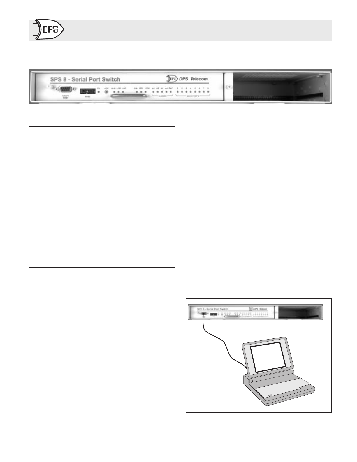
8 Port Serial Switch
Fig. 1 - SPS 8 expands ASCII Ports up to Eight Times
Operation Guide
Table Of Contents
Overview ....................................1
Functional Schematic ..........................2
Typical MUX Applications .....................2
Shipping List .................................2
Installation...................................2
Configuration ................................2
Modem Tuning ...............................4
LED Display Status............................5
ACK Button..................................5
Hardware Connections.........................5
Connectorized Model Layouts...................6
Operation....................................7
Specifications.................................8
Options & Model Numbers .....................8
Overview
DPS’s 8 Port Serial Switch allows you to connect up to eight
data sources to one port on a collection device , such as the Net
Dog 82IP. Commands from an interrogating ASCII terminal
control the switch to route data to the appropriate port. Each
channel has a 16K buffer that allows data to be moved between
ports at different data rates.
The 8 Port Serial Switch is available with wire-wrap pins for
external connection or with DB9 connectors.
The Switch consists of nine interface ports interconnected
and controlled by a processor. Associated with each port is a
“docking module” socket that allows the physical interface to
the outsideworldto be configured to match the associated communications channel or device. This model of the 8 Port Serial
Switch is equipped with RS 232 interfaces on each port.
The 8 Port Serial Switch is housed on a plug-in board that fits
in a 1-3/4" rack-mount housing. The back of the housing provides DB9 connectors for connecting the associated devices.
The P.C. board can be changed rapidly without removing any
of the connections.
The front panel of the 8 PortSerial Switch provides LEDs for
monitoring unit activity and a craft port for configuration.
There is a fuse alarm indicator on the front panel and a fuse
alarm output relay that activates when the fuse blows.
The 8 Port Serial Switch operates on either -24 or -48 Volts
DC, depending on the option. (Options are described in the Options and Model Numbers section on page 8.)
Variable Data Rates
In addition to switching between multiple ports, the 8 Port
Serial Switch will select a preset data rate for each port. Available data rates are 300, 1200, 2400 and 9600 Baud.
T/MUX Software
The MUX is programmed for various parameters with
T/ASCMUX software, running under T/Config software on a
personal computer. The craft port on the front panel is easily
accessed any time the configuration needs changing.
Downloadable Firmware
Future product upgrades will be easy to install with the
downloadable firmware. Simply connect a P.C to the craft port
and load the new firmware from a diskette.
D-PC-186-10A-XV 1 OG119699
September 16, 1999
T/ASCMUX
T/kda
Fig.2-8Port Serial Switch Configures at the Front Panel
Craft Port
Page 2
CTS
GND
TX
RX
DSR
RTS
RS232
-BATT.
GND
Fuse
Alarm
Common
Port
Craft
Port
LED's
ProcessorBuffer
Power
Regulator
Port
Port
Port
Port
CTS
GND
TX
RS232
RX
1
DSR
RTS
Port
2
CTS
GND
TX
RX
3
DSR
RTS
Port
4
Port
5
CTS
GND
TX
RX
6
DSR
RTS
Port
7
CTS
GND
TX
RX
8
DSR
RTS
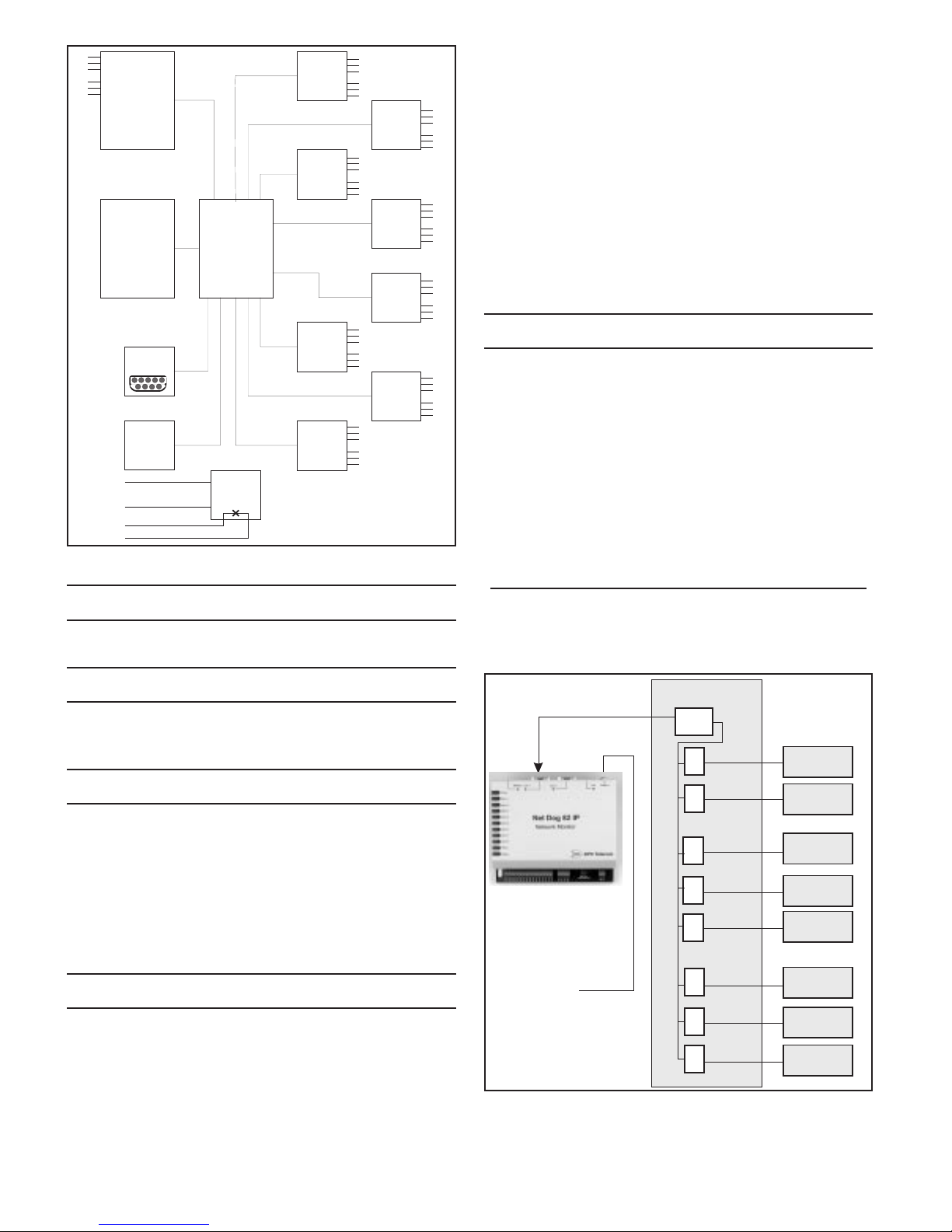
Fig.3-8Port Serial Switch Routes Data by
Microprocessor
Functional Schematic
The illustration in Fig. 3 shows a functional schematic of the
8 Port Serial Switch.
Connect power wires to the wire wrap J2 or to the
¤
connectors in back of the Switch. See Hardware
Connections elsewhere in this guide for wire wrap or
CTS
GND
TX
RX
DSR
RTS
CTS
GND
TX
RX
DSR
RTS
CTS
GND
TX
RX
DSR
RTS
connector pin layouts.
Connect communications lines to other devices to
¤
the Switch.
Verify that the power is correct for the option (-24 or
¤
-48 VDC). See Options and Model Number section
at the end of this Operation Guide.
Insert the fuse in the fuse holder on the front panel.
¤
Connect the Switch Craft Port to a a dumb terminal
¤
or a P.C. with terminal emulation software. Refer to
the Configuration Section below for more
information.
Configuration
CTS
GND
TX
RX
DSR
RTS
The 8 Port Serial Switch is configured with a program called
T/ASCMUX. T/ASCMUX runs under a host program called
T/Config, which can host configuration software for a variety
of DPS products.
NOTE: T/ASC MUX also works with ASCII MUX product.
T/Config is included on the disk supplied with the Switch
unit. If T/ASCMUX is being run on a computerthat already has
T/Config installed, we recommend that you re-install the
T/Config on the T/ASCMUX disk to be sure the latest version
is running.
T/Config and T/ASC MUX Install
Place the T/ASCMUX disk in the A drive and type
a:<ENTER>.
Type TINSTALL <ENTER>. Follow the directions on the
screen.
Typical MUX Applications
The illustration in Fig. 4 shows the 8 Port Serial Switch interfacing 8 ASCII sources to a DPS Net Dog 82IP equipped with
an ASCII interrogating port.
Shipping List
Verify the following items were included in the shipment:
¤
8 Port Serial Switch in a 1 rack unit case
¤
2 Mounting Brackets
¤
1 Real Fuse; 1 Dummy Fuse (for shipping)
¤
T/ASCMUX Software
¤
Configuration Cable
¤
ASCII MUX Operation Guide
Installation
¤
Unpack the 8 Port Serial Switch and all accessories.
¤
Attach the mounting brackets for the required rack
width.
¤
Mount the 8 Port Serial Switch case to the Rack.
¤
Remove fuse.
8 Port Serial Switch
Common
Port
Port
Port
Port
Port
Port
Port
Port
Port
1
2
3
4
5
6
7
8
Serial Port
Netdog 82IP
To ASCII
Terminal via
LAN or Dial Line
Fig. 4 - ASCII MUX Gathers Alarm Data from
Distributed data Sources into one Port
Data Sources
Source #1
Source #2
Source #3
Source #4
Source #5
Source #6
Source #7
Source #8
OG119699 2 D-PC-186-10A-XV
September 16, 1999
Page 3
Start T/ASC MUX
Select the hard drive and the T/Config directory.
Type T/CONFIG <ENTER>.
Highlight T/ASCMUX <ENTER>.
The first screen will request initials. Enter your initials and
press <ENTER>.
Fig. 5 - Main Menu Lists the Functions Available in
T/ASCMUX
Main Menu
The Main Menu (Fig. 5) lists the functions available in
T/ASCMUX. Each of these Main Menu items is explained in
the following paragraphs. Most fields will have an associated
“default box” that appears. To select from the default box press
Tab and use the Tab key or cursor arrows to highlight the desired value, then press <ENTER>.
Fig. 6 - Enter a New Name in the Open ASCII window or
Select from Default Box
Open ASCMUX
This selection is used to open an existing configuration or to
name a new one. When this function is selected a box will appear with three fields. See Fig. 6 and Table A.
Table A - Field Descriptions in the Open ASCII MUX
Screen
Field Description
NAME Enter a new name or select an existing one from the de-
fault box. The name will appear in the Title Bar at the
top of the screen at all times. The name should be exclusive to this configuration.
SITE NAME Enter a name that describes the location of the unit.
(Mandatory field)
COMMENT Optional field for additional identifying information,
such as date or initials of preparer.
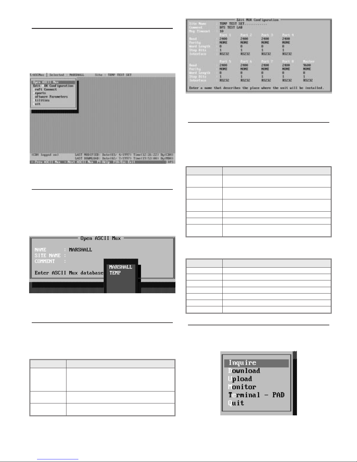
Fig. 7 - Set ASCII Port Parameters in the Edit
Configurations Screen
Edit MUX Configuration
This selection presents the Edit MUX Configuration screen.
See Fig. 7. Set parameters for each of the eight ports and the
MUX (common) Port in this screen. Parameters and their values are explained in Table B.
Table B - Field Descriptions for the Edit Configuration
Screen
Field Description
Msg Timeout Time to delay before aborting incomplete message. En-
ter in tenths of seconds (10-255). Default is 100.
Baud Off, 300, 1200, 2400 and 9600. Select from default box.
Default 1200 Baud.
Parity EVEN, NONE, ODD. Select from default box. Default
NONE.
Word Length 7 BITS, 8 BITS. Select from default box. Default is 8.
Stop Bits 1 BIT, 2 BITS. Select from default box. Default is 1.
Interface TTL, RS232, RS422, RS485, 202. Select from default
box. Default is RS232.
Several “Hot Keys” are available in the Edit MUX Configuration screen. The line at the bottom of the screen lists them.
Table C - Hot Keys in the Edit Configurations Screen
Key Description
Tab Select default box.
Up Arrow Go to previous field.
F1 Go to previous port.
F2 Go to next port.
F8 Save.
F9 Help.
F10/Esc Go to first field or exit.
Craft Connect
Use this menu item when connecting to the craft port on the
front of the MUX for downloading or other functions.
NOTE: When using thisfunction, the MUX port is not active.
Fig. 8 - Select from Several Craft Port Functions in the
Craft Connect Menu
D-PC-186-10A-XV 3 OG119699
September 16, 1999
Page 4

Table D - Craft Connect Functions
Function Description
INQUIRE
DOWNLOAD Configure the unit using the selected configuration (re-
UPLOAD Retrieve configuration from the unit. Overwrites se-
MONITOR Monitor operational status. (Fig. 6) Screen shows local
Terminal - PAD Observe data on any port. Select port with function key.
QUIT Exit this function and return to the Main Menu.
Retrieve and display the unit*s configuration status.
fer to the title bar). Press <ENTER> to start.
lected configuration. Press <ENTER> to start.
alarm and control point status. (Shown in this screen
only.) It also displays four operational status points, for
use by DPS Technical Support. Press F7 for the Modem
Tuning window.
This function is not fully implemented at this time.
Fig. 9 - Monitor Screen Shows Status of Auxiliary Alarms
and Control Relay
Fig. 10 - Press F7 while in the Monitor Mode to Access the
Tune Modem Window
Modem Tuning
If the MUX is equipped with modems on any of the ports, set
the modem levels while in the monitor mode. Press F7 to access
the Modem Tuning Window (Fig. 10). Use the + (plus) and (minus) keys to select the port (selected port is displayed in the
first field of the window). With a level meter on the port to be
adjusted, use the keys listed in the window to control the transmit and raise or lower the level, as needed. The receive portion
of the modem has an AGC input, so requires no adjustment.
NOTE: Do not tune above -4dbm or below -34dBm as the
waveforms become distorted at those levels.
ular unit is configured. Several configurations can be reported.
A query box will ask for starting and ending configuration
names (press Tab to see a default box listing of existing configurations), report destination andfile name (if outputting to file).
Fig. 11 - Configuration Computer Com Port Parameters
must be set before Downloading the MUX or Switch.
Software Parameters
Before a configuration can be downloaded, it is necessary to
set the configuration computer’s com port to match the MUX
craft port parameters. That is done in the Software Parameters
function. See Fig. 11 and Table E.
A sub-menu appears when this function is selected. Select
“Communications” from this sub-menu.Parameters and their
values are given in Table E. Select“Parameters” if you wish to
specify the report directory (Fig. 12).
Table E - Software Parameters Functions
Function Description
COM PC Com Port number (1-4).
BAUD Set only at 9600 Baud.
STOP BITS Select 1.
DATA BITS Select 8.
PARITY Select NONE.
MAX TIMEOUT Time to wait for a response (50-9999 Milliseconds). De-
fault is 3000.
MAX RESEND Number of requests before a timeout will be declared
(0-100). Default is 20.
SEND DELAY Amount of time before the next request is made. (1-100
seconds). Default is 1.
DIAL TYPE Not applicable.
QUIT Exit this function and return to the Main Menu.
Parameters Menu Item
Report Path Specify the Directory for report files. Normally this is
“Tconfig. See Fig. 12.
Reports
Use this menu item to run configuration reportsto the screen,
printer or file. Reports are useful in creating records and reference files. Such files allow future reference to see how a partic-
OG119699 4 D-PC-186-10A-XV
Fig. 12 - Select “Parameters” from the Software Parame-
ters Menu to Define the Directory for Reports
September 16, 1999
Page 5

Utilities
Use this menu item to copy or delete configurations and to
perform corrective functions at the direction of DPS technical
support.
A sub-menu appears when this function is selected. See Fig.
13 and Table F.
Table F - Utilities Functions
Function Description
COPY ASCII
MUX
REBUILD KEY
FILES
DELETE ASCII
MUX
TERMINAL General purpose dumb terminal.
QUIT Exit this function and return to the Main Menu.
Copies another configuration into the selected
configuration.
Repairs damaged index files. Use only at the direction
of DPS technical support.
Deletes the selected configuration from the database.
NOTE: The “Selected Configuration” is listed on the Title
Bar at the top of the screen.
Quit
Use this menu item to exit T/ASCMUX.
LED Display Status
Dual-color LED indicators on the front panel give maintenance personnel quick diagnostics of the operational status of
the ASCII MUX. TableG explains the LED functions in detail.
Table G - ASCII MUX LED Display Functions
LED Condition Meaning
FA OFF Fuse Normal
RED Fuse Blown
ALM RED Craft port is active.
LOD RED Download in progress.
LOC RED Craft Port active
CM1 BLINKING
ER1 RED Error condition.
CFG RED Needs download.
A1 - A4 RED Alarm point active.*
RLY RED Control relay operated.*
ASCII PORTS
1-8
RED
BLINKING
GREEN
GREEN Normal mode.
BLINKING
GREEN
BLINKING
RED
*Alarm and Control functions are reserved for possible
future use.
Receiving data on common port.
Transmitting Data on common port.
Transmitting data on respective port.
Receiving data on respective port.
Fig. 13 - Select Functions from Utilities Menu
ACK Button
The ACK Button performs an LED test. While the ACK button is held in LED’s will illuminate in their solid color, alternating from green to red and back.
Hardware Connections
The following illustrations show wiring pinouts for the
MUX.
DSR
GND
54321
9
RTS CTS
8
Craft Port Connector
The Craft Port is a female RS232 DB9 connector used as a
direct link into the MUX. Normally used to configure the
MUX. See Fig. 15.
RX
PIN # SIGNAL DESCRIPTION
TX
6
7
1
NC
2
TX
3
RX
4
NC
5
GND
6
NC
7
CTS
8
RTS
9
NC
Fig. 15 - Craft Port Pin-Outs
Not Connected
Transmit Data
Receive Data
Not Connected
Ground
Not Connected
Clear To Send
Request To Send
Not Connected
SPS-8
CRAFT
PORT
Fig. 14 - LED Indicators on the Front Panel Show Operational Status of the 8 Port Serial Switch.
D-PC-186-10A-XV 5 OG119699
September 16, 1999
DPS Telecom
FA
LOC
ER1
CFG
A1 A2 A3 A4 1 2 6 4 5 6 7 8RLYACK ALM CM1LOD
ALARMS ASCII PORTS
Page 6

Wire Wrap Pin Layouts
and Rear Panel Connectors
Figs. 16 through 17 show the pinouts for J1 and J2 wire wrap
pins a on the rear panel.
J3 J1 J2
Fig. 16 - Wire-Wrap Connectors are Accessed from Rear
Connectorized Model Layouts
Figure 18 shows the back panel of a connectorized Switch.
Refer to Fig. 19 for the connector pin-outs.
2143658712111413161518 38
10
9
20
22 42
24 44
26 46
28 48
30 50
32 52
34 54
36 56
17 37
19 39
21 41
23 43
25 45
27 47
29 49
31 51
33 53
35 55
J1 Pin Layout
PIN # DESCRIPTION
1
N/C
3
CTS PORT 1
5
TXD PORT 1
7
N/C
9
CTS PORT 2
11
TXD PORT 2
13
N/C
15
N/C
17
N/C
19
N/C
21
CTS PORT 3
23
TXD PORT 3
25
N/C
27
CTS PORT 4
29
TXD PORT 4
N/C
31
N/C
33
N/C
35
N/C
37
CTS PORT 5
39
TXD PORT 5
41
N/C
43
CTS PORT 6
45
TXD PORT 6
47
N/C
49
N/C
51
N/C
53
N/C
55
Fig. 17 - Non-Connectorized Models Connect Directly to Wire-Wrap Pins at Back of Switch
PIN #
2
4
6
8
10
12
14
16
18
20
22
24
26
28
30
32
34
36
38
40
42
44
46
48
50
52
54
56
COMMON PORT PORTS 1 - 8
40
DESCRIPTION
N/C
GND PORT 1
RXD PORT 1
RTS PO RT 1
GND PORT 2
RXD PORT 2
RTS PO RT 2
N/C
N/C
N/C
GND PORT 3
RXD PORT 3
RTS PO RT 3
GND PORT 4
RXD PORT 4
RTS PO RT 4
N/C
N/C
N/C
GND PORT 5
RXD PORT 5
RTS PO RT 5
GND PORT 6
RXD PORT 6
RTS PO RT 6
N/C
N/C
N/C
J9 J10 J11 J12 J13 J14 J15 J16 J17 J18 J19 J20 J21 J22
J2 Pin Layout
PIN # DESCRIPTION
1
CTS PORT 7
3
TXD PORT 7
5
N/C
7
CTS PORT 8
9
TXD PORT 8
11
N/C
13
N/C
15
N.C. CTRL 1*
17
COM. CTRL 1*
19
N/C
21
ALARM 1 -*
23
ALARM 2 -*
25
ALARM 3 -*
27
ALARM 4 -*
29
N/C
31
N/C
33
N/C
35
N/C
37
N/C
39
TXD COMMON (MUX) PORT
41
DCD COMMON (MUX) PORT
43
N/C
45
FUSE ALARM
47
N/C
49
N/C
51
N/C
53
N/C
55
- BATTERY
FUSE ALARM
(NORMALLY OPEN FORM 'A' RELAY)
*For Future Implementation
DB9 FEMALE CONNECTORS
FUSE ALARM AND CONTROLS
PIN #
DESCRIPTION
2
GND PORT 7
4
RXD PORT 7
6
RTS PORT 7
8
GND PORT 8
10
RXD PORT 8
12
RTS PORT 8
14
N/C
16
N.O. CTRL 1*
18
N/C
20
N/C
22
ALARM 1 +*
24
ALARM 2 +*
26
ALARM 3 +*
28
ALARM 4 +*
30
N/C
32
N/C
34
N/C
36
N/C
38
DTR COMMON (MUX) PORT
40
RCV COMMON (MUX) PORT
42
GND COMMON (MUX) PORT
44
N/C
46
FUSE ALARM
48
N/C
50
N/C
52
N/C
54
N/C
56
GROUND
45
46
J20-J22
Not Used
ALARM POINTS 1 - 4
Frame
Ground
GND
-BATT
POWER
TERMINAL
BLOCK
J9 - J17
PINOUT FOR RS232 INTERFACE
1 ( N/C)
2(TXD)
3 ( RCV)
4 ( N/C)
5 ( GND)
6 ( N/C)
7 ( DCD)
8 ( DTR)
9 ( N/C)
Fig. 19 - Female DB9 Connector Pin-Outs on Rear of 8 Port Serial Switch.
OG119699 6 D-PC-186-10A-XV
Fig. 18 - Rear Panel of Connectorized Model
J18
PINOUT FOR FUSE ALM & CTRLS
1(F/ACOM)
2 (F/A N.O.)
3 ( N/C)
4 ( N/C)
5 ( N/C)
6 (CTRL N.C.)
7 (CTRL N.O.)
8 (CTRL COM)
9 ( N/C)
PINOUT ALARM POINTS
1 (ALM 1A)
2 (ALM 1B)
3 (ALM 2A)
4 (ALM 2B)
5 (ALM 3A)
J19
6 (ALM 3B)
7 (ALM 4A)
8 (ALM 4B)
9 ( N/C)
September 16, 1999
Page 7

Operation
Dumb Terminal Operation
With a dumb terminal at the common port (either directly or
via some transport media), use the following procedure to select the desired ASCII port:
1. After the terminal is connected, type @@@.
2. At the prompt, the currently selected port number will be
displayed.
3. Type S followed by the number of the desired port
<Enter>.
4. Type C<Enter> to connect to the desired port.
Operation via Net Dog
To access the common port of the SPS 8 using the Net Dog’s
reach through capability:
1. Connect a Telnet Client to TCP port 2002 at the address of
the desired Net Dog.
2. Get the clear channel.
3. After the terminal is connected, type @@@.
4. At the prompt, the currently selected port number will be
displayed.
5. Type S followed by the number of the desired port
<Enter>.
6. Type C<Enter> to connect.
D-PC-186-10A-XV 7 OG119699
September 16, 1999
Page 8

Specifications
"
Options & Model Numbers
Specifications for the Switch are shown below.
Dimensions 17.0"(W) X 12.0"(D) X 1.75"(H)
Mounting The MUX can be mounted in a 19" or 23" rack.
The MUX unit can also be wall mounted.
Power Input -24 DC unit: -18 to -36 VDC @ 200 mA
-48 DC unit: -36 to -72 VDC @ 180 mA (max)
30 mA (typical).
Fuse 1/2 Amp
Operating Temperature Range
0 degrees to +60 degrees Celsius.
Humidity 0% to 95% non-condensing
Interface 1-RS232 (DB9) Craft Port on the front,
9 DB9 connectors on the back.
Buffers 16k byte on each MUX channel.
Electrical Interface:
Common Port: RS232
Eight Channel (source) Ports: RS232
Data Rates: 300, 1200, 2400 and 9600 Baud.
All specifications are subject to change without notice.
The 8 Port Serial Switch part numbers and options are listed
below. These options are constantly expanded. As a result,
more options may be available than are listed below. Contact
your distributor for currently available options.
D-PC-186-10A-02
8 Port Serial Switch: RS 232, Connectorized,
-24VDC.
D-PC-186-10A-04
8 Port Serial Switch: RS 232, Connectorized,
-48VDC.
DPS INC
"Your Partners in Telemetry Monitoring Systems
OG119699 8 D-PC-186-10A-XV
4955 East Yale Avenue - Fresno, CA 93727 - Phone (559) 454-1600 / (800) 622-3314 - FAX (559) 454-1688
e-mail: sales@dpstele.com
Visit our Web site at http://www.dpstele.com
September 16, 1999
 Loading...