

Page 1
NetGuardian 832A/864A G5 ODOT
USER MANUAL
Vis it our websit e at www.dpstelecom.com for the latest P DF manual and FAQs.
November 22 , 2016
D-UM-NETG5-12114
Firmware Version 5. 3L
Page 2

Revision History
November 22, 2016
April 13, 2016
March 24, 2016
June 1, 2015
Minor Updates
Added steps to s et up Kenwood Radio
Keyed 202 Added
Initial ODOT Release
This document contains propri etary information which is protected by copyright. All rights are reserved. No part of this
document may be photocopied without pri or w ritten consent of DPS Tel ecom .
All software and manuals are copyri ghted by DPS Tel ecom . Said software and manuals m ay not be reproduced, copied,
transmi tted or used to make a derivative work, by either mechanical, electronic or any other means in whole or i n part, without
prior wr itten consent from DPS Tel ecom , except as required by United States copyri ght laws.
The material in this manual is for information purposes and is subject to change without notice. DPS Telecom shall not be
liable for errors contained herein or consequential damages in connection with the furnishing, performance, or use of this
manual.
© 2016 DPS Telecom
Page 3

Contents
Visit our w ebsite at www .dpstelecom.com for the latest PDF manual and FAQs
NetGuardi an G5 Overview1 1
About This M anua l2 2
Shippi n g Li st3 2
Port Alloc ation3.1 6
Optional Accessories4 6
Specifications5 10
Hardw are I n stal l ation6 12
Tools Needed6.1 12
Mounting6.2 12
Power Connecti on6.3 13
LAN Connection6.4 15
Telco Connect ion6.5 17
Alarm and Control Relay Connections6.6 17
Alarm and Control Relay Connector Pinout Table (832A)6.6.1 18
Alarm and Control Relay Connector Pinout Table (864A)6.6.2 19
Discretes 1–24 Connector Pinout Diagram (832A)6.6.3 20
Analogs1–6/Discretes 25–32/Relays 1–8 Connector Pinout Diagram (832A)6.6.4 21
Discretes 1- 48 Connector Pinout Diagram (864A)6.6.5 22
Analogs 1-6/Discretes 49-64/Relays 1-8 Connector Pinout Diagram (864A)6.6.6 23
Analog Dipswitc hes6.6.7 24
Integrated Temperature and Battery Sensor (Optional)6.6.8 25
6.6.8.1
Data Ports6.7 26
Connecting NetGuardian Acc es s ories6.7.1 27
GLD/ECU Expansion Port (RS-485)6.7.2 27
Hardware Options6.8 27
Integrated 10/100BaseT Ethernet Switc h (Optional)6.8.1 28
Integrated T1/E 1 P ort6.8.2 28
GSM/GP RS or CDMA Wireless M odem Top Board (Optional)6.8.3 30
6.8.3.1
+12 or +24 VDC Sensor Power Supply6.8.4 31
Hardware Acc eleration (SSL/SS H)6.8.5 32
Integrated 8 Additional Serial Data Ports6.8.6 32
Analog Step Sizes
Wireless M odem Act i vation
25
30
D-Wire Sensor Inputs6.8.7 33
6.8.7.1
Optional 66 Block Connect or (832A)6.9 33
Connecting D-Wire Sensors
33
Page 4

Optional 66 Block Connect or (864A)6.10 36
Optional Hinged Wire-Wrap Back Panel6.11 38
Lexan Wire-Wrap Cover6.11.1 39
Optional Hinged Pluggable Back P anel6.12 40
Optional Hinged Amphenol Back P anel6.13 43
Alarm and Control Relay Connector Pinout Tables (KDA 864)6.13.1 46
Controls6.14 47
Bypassing Pass word6.15 48
LCD Display7 49
Alarm and Control Status Mes s ages7.1 49
LCD Command Menu7.2 50
Sound off7.2.1 51
Reboot7.2.2 51
Run Config7.2.3 51
Contrast7.2.4 52
Alarm S pea ker8 52
Front Pan el LEDs9 53
Back Pa nel LEDs10 54
Configuring the Ne tGua rdi an11 55
RADIUS Authenticat ion (Available as of Firmware 5.0I)11.1 55
Connecting to the Ne tGua rdi an12 55
... via Craft Port12.1 55
... via LAN12.2 57
TTY Interface13 58
Est ablis hing an SSH Sess ion13.1 59
Unit Configuration13.2 59
Ethernet Port Setup13.2.1 59
13.2.1.1
13.2.1.2
T1/E1 W A N Sett i ngs
New! Backup Mode
60
61
SFP Fiber Connecti on (For Fiber Build Option)13.2.2 61
Edit P PP P ort13.2.3 62
Tune 202 Modem13.2.4 63
RADIUS Configuration13.2.5 64
UnitKal13.2.6 65
New! - TTY Command Mode13.2.7 65
DSCP Configuration13.2.8 68
Monitoring13.3 72
Monitoring the NetGuardian13.3.1 72
13.3.1.1
Monitoring Base Alarms
72
Page 5

13.3.1.2
13.3.1.3
13.3.1.4
13.3.1.5
13.3.1.6
13.3.1.7
13.3.1.8
Monitoring Ping Targets
Monitoring and Operating Relays (Controls)
Monitoring Analogs
Monitoring Syst em A larms
Monitoring Data Port Ac t ivity
Monitoring the Accumulation Timer
Monitoring DSCP Devic es
73
73
74
74
75
75
76
Viewing Live Target Pings13.3.2 77
Proxy M enu13.3.3 78
Event Logging13.3.4 78
Back ing Up NetGuardian Configuration Data via FTP13.3.5 79
13.3.5.1
Reloading NetGuardian Configuration Data
79
Debug Input and Filter Options13.3.6 80
Reference S ection14 81
Display Mapping14.1 81
System Al arms Dis play M ap14.1.1 84
SNMP Manager Functions14.2 88
SNMP Granular Trap Packets14.3 89
Trap SNMP Logic14.4 91
ASCII Conversion14.5 91
RADIUS Dictionary File (Available on Resource Disk )14.6 92
Frequently Asked Que stions15 93
General FAQs15.1 93
SNMP FAQs15.2 95
Pager FAQs15.3 96
Techni ca l S up port16 97
End User Li cense Agre ement17 98
Page 6

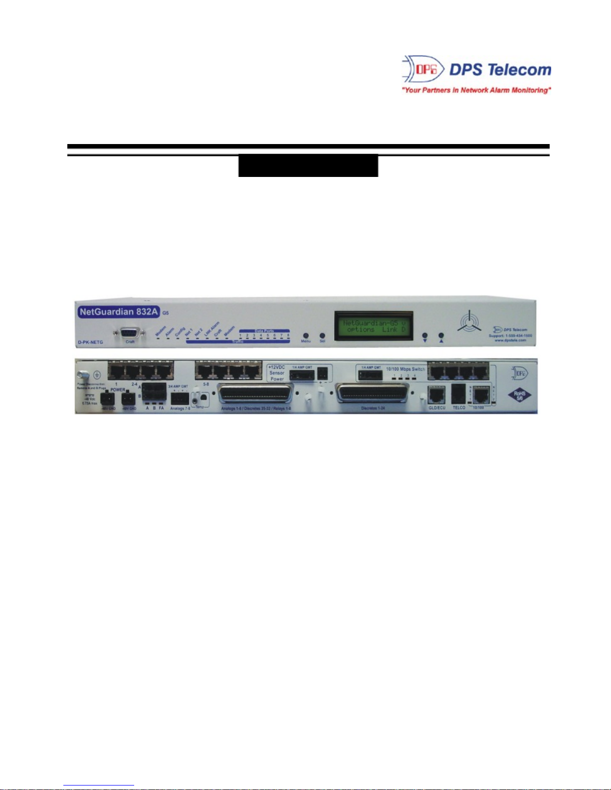
1
NetGuardian G5 Overview1
Fig. 1 . 1. The NetGuard ian has all t he to ols you nee d to manage you r remote site.
The NetGuardian G5 — The Intelligent RTU for Complete Site Management
The NetGuardi an G5 is a RoHS 5/6-complia nt, LAN-ba sed, SN MP/DCPx remote tel emetry unit. T he
NetG uardi an has all th e too ls you n eed t o manage yo ur remote site s, includi ng bu ilt-i n ala rm monit oring,
pag ing and e mai l capab ilities that can eliminate the ne ed fo r an al arm master.
With the Ne tGua rdi an, yo u can:
· Monito r 32 di screte a larms, 32 pi ng al arms, an d 8 analo g alarms
· Contro l remote site equ ipment via 8 terminal server ports an d 8 control rel ays
· Monito r your remote site f rom anywh ere using the NetGu ardia n's built -in Web Browser Interface.
· Report alarms to multi ple SNMP man agers or th e T/Mon NOC Alarm Monitoring System.
· Report alarms via LA N or dia l -up conn ection.
· A utomati cal ly send pager and email a larm noti f ications 24/7.
· Connect multiple concurren t users via Telne t ove r LA N to tel ecom switches, servers, radios,
PBX s an d oth er equ ipment.
· Monito r discrete and analog t hreshol d ala rms.
· Ping IP netwo rk devices and verify that th ey're onli ne and op erati ng.
· NEW! Backu p Mode: Redund ant L AN conn ectivi t y.
New: The NetGu ardian G 5 suppo rt s serial bau d rate s up t o 115 , 200, addi t ional RS485 for GLD/ECU
exp a nsion pol li ng port , trip le CPU speed for faster processing, optional b uilt-in 4-port switch (tie d to
NET2), optional external t emperature sensor, analog rea dings accurate to within +/- 1 %, du al 10 / 100
NICs (isolated ) repla cin g the 10BaseT NICs, SN MPv2 c, SNMPv2c Inform trap, an d SNMPv3.
TIP: This is the ba sic installation (hardware) manua l. For softwa re and web configuration manua ls,
ple a se refer to ap pro p ri at e manua l on th e Resource CD provi de d with yo u r un it , v isit www.dpstele.com/
pdfs/op_guides
Stand-a l o n e local visibili ty
Y ou don't ne ed an alarm master unit to monito r your site with t he NetGuardian . With t he NetGua rdian's
bui lt-in Web Bro wser Interface, you can access the NetGu ardia n, view alarms and control remote site
devices from any comput er anywhere in your network.
24/7 pager and email alerts - no master needed
Out of the box, the NetGua rdian support s 24 / 7 pager and email repo rt ing. Send alarms directly to
mainte nance technician s in t he fi eld, eve n when no one's in th e offi ce.
Connect via LAN to telecom switc h es, s ervers, radios and more
Each of the NetGua rdian's eight serial ports can be i ndividuall y confi gured to serve as a craft port, a
channel port or a T CP o r UDP reach-through p ort, giving y ou LAN-based terminal server access to up t o
eig ht serial devices.
Page 7
NEW - RADIUS Authenticatio n (As o f fi rmware v5.0I)
Tak e the securit y of your alarm remote s to t he ne xt leve l with RADIUS aut hentication. N ow t he
Net G uardian G 5 can in t eract w ith you r R ADIUS server , in t egrat in g it as part of your enterprise
management.
Reports to multipl e SNMP managers and T/Mon NOC simultan eousl y
The NetGuardi an reports to both the T/Mon NOC Alarm Monito ring System and any SNMP manager.
Y ou can simultaneo usly fo rwa rd ala rms from the NetGu ardia n to T/ Mon NOC and multiple SNMP
managers at multiple IP addresses. Alarms can also be configured t o dispat ch to one, some, or al l
SNMP managers.
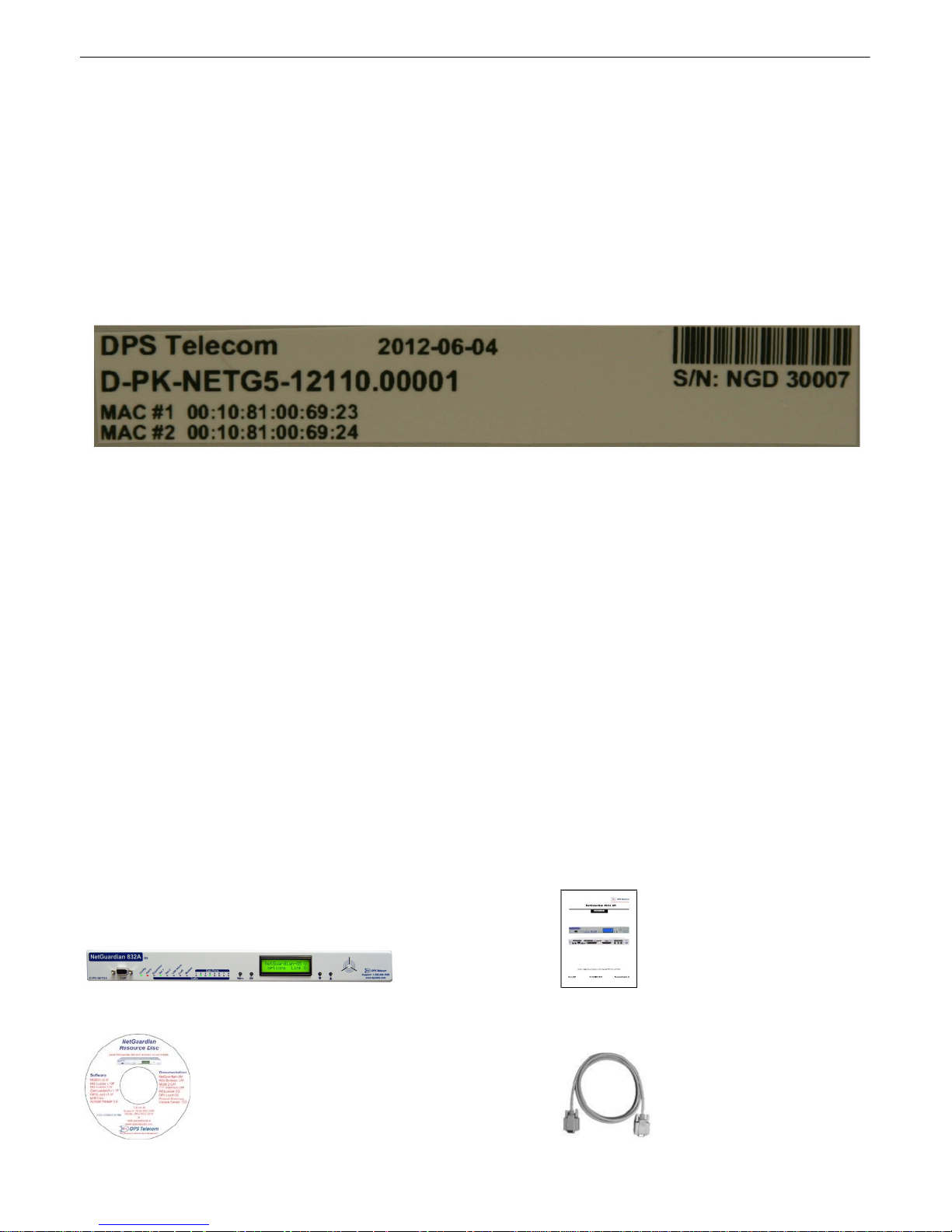
Fig. 1 . 2. You r Ne t Guardia n will come with a label o n the f ront panel that wi ll in clu de th e Produ ct Number,
Seria l Number, a nd MAC Addresses. This will help you if you ever n eed to contact DPS ab out your
device. Th e barcod e and seri al number can be used to f acilia t e your int ernal tracking.
2
About T h i s Manual2
There are t hree separate user manual s for t he NetGua rdian G5 : t he Hardware Manual (which you're
read ing now), the N GEditG5 U ser Manu al, and th e NetG uardi an G5 Web Interface User Manual.
This Hardwa re Manual prov ides instructions for hardware i nstallation and using t he TTY interface. The
NGEditG 5 and Web Interface User Manuals, inclu ded on th e NetGuard ian Resource CD, provide
instructio ns for configurin g the NetGu ardian using the Wind ows-based N GEditG 5 utility software o r t he
Web I nterface.
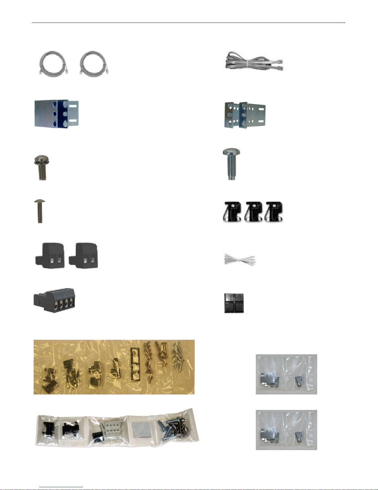
Ship p i n g L i st3
While unpacking the NetGuardian, plea s e make sure that all of the following items are included. If some parts are
missing, or if you ever need to order new parts, please refer to the part numbers liste d a nd call DPS Telecom at
(80 0) 622-3 314.
NetGuardia n 832A G5: D-PK-NETG5-12001 NetGuardian G5 Hardw are
NetGuardia n 864A G5: D-PK-NG864-1 2001 Manual D-UM-NETG5
Page 8
3
NetGuardia n G5 Resource CD DB9M-DB9F Download Cable 6 ft.
(inclu d es manual s, MIBs, and softw are) D-PR-045-1 0-A-04
Two Ethernet Cables 14 ft. Telephone Cable 6 ft.
D-PR-923-10B-14 D-PR-045-1 0A-01
23" Ra ck Ears 19" Ra ck Ears
D-CS-325-10A-01 D-CS-325-1 0A-00
Eight 3/ 8" Ear Screws (F ) Four Stand ard Rack Screws (H)
2-000-60375-05 1-00 0-12500-0 6
Four Metric Rack Screws (G) Three 3/4 -Amp GMT Fuses (B)
2-000-80750-03 2-74 1-00750-0 0
Two Large Power Connector Plugs for Main Po wer (C) Four Cable Ties
2-820-00862-02 (Sixteen with hing ed pan el)
4 Pin Ana l o g Conn ector (D) Pads (E)
2-820-00814-02 2-015-00030-00
A B C D E F G H Optional
+
Screws an d connectors a re packaged in a sealed hardware kit, s h o wn above
+
Page 9

(Hardware kit contai n i n g a WAGO connector)
4
Page 10

5
Optional Items
Two 3/4-Amp GMT Accesso ry Fuses (A) One Small Connector for Sensor Output
2-741-00250-00 2-820-00812-02
External Temperature Sensor 20 ft. External Temp erature Sensor
D-PR-991-10A-07 D-PK-SENSR-12037
Page 11
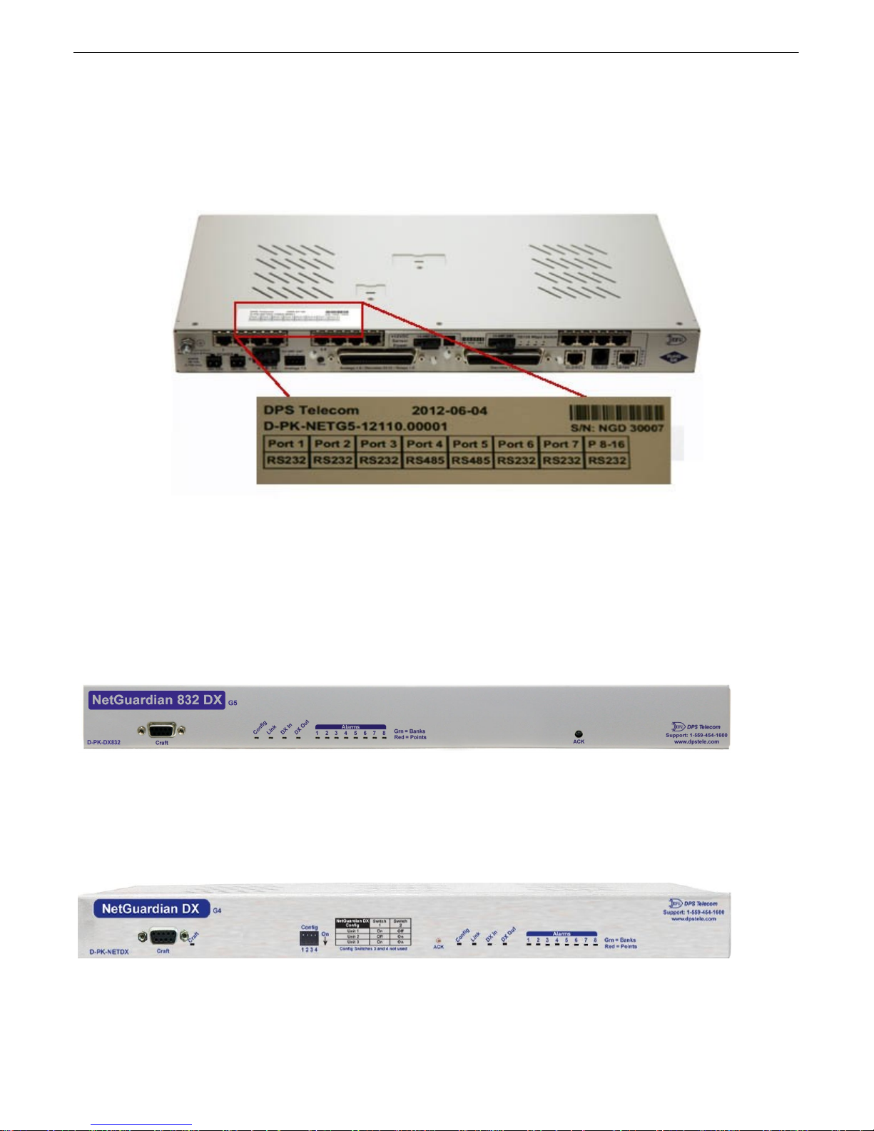
Port Allocation3.1
Locate d on t he top of the unit in the back le f t corn er is the Port Allo cat i on Sti cker. Thi s sticker i nclude s
your part number (D-PK-NETG 5-### ##.# #### ), wh ich specifies your bu ild option. The table belo w i t lists
your port allo cation. T his label display s serial electrical inf ormation abo ut ea ch o f t he po rt s, fo r exa mpl e
if th e port hardware is config ured for RS232 , RS4 85, 202, e t c.
6
Optional Accessories4
Y ou can e xtend the capab ilities of th e NetG uardi an th rough accessory units that prov i de greate r discrete
ala rm capacity, remote audiovisual alarm not ificati on, v isual surv eill ance of remote sites, an d oth er
options. If you wo uld like to o rder an y of these accessories, or if you would like more in f ormation about
them, call DPS Telecom at (800) 622 -3314.
NetGuardia n Expans i o n (NetGuardian 832A/8 64A DX G5)
D-PK-DX832/D-PK-DX864
The NetGuardi an G5 expansions provide and additional 32 al arms for your NetGu ardian 83 2A model or
64 p oint s for your 864A, providi ng a t otal of 12 8 or 25 6 alarms with 3 expansio n uni t s. Each e xpansion
comes stand ard with an additional 8 con t rol rel ays and 8 analog inp uts, and is avai labl e with an optio nal
8 po rt hub. (Opt iona l builds are also avail able witho ut contro ls, anal ogs, or both.)
NetGuardia n Expans i o n (NetGuardian DX G4)
D-PK-NETDX-12022.00001
The NetGuardi an Ex pansion G4 provides an additi onal 48 discrete and 8 relay contro ls. Up t o thre e
NetG uardi an Ex pansions can be daisy-chained off on e N etGuardian, prov idin g a to t al of 176 discrete
Page 12
7
and 32 analo g alarm point s.
NetGuardia n Expans i o n
The NetGuardi an 480 (NG480) Expansion provi des an addit iona l 80 alarms and 4 relays. With 80
discrete al arm inp u ts, yo u can ea sily fo rward al l the al a rms of a small to medi um-sized site.
NetGuardia n E16
D-PK-DXE16
A dding the N etGuardian E1 6 provides an ad diti onal 16 alarm points and 16 contro ls. One N etGuardian
E16 u nit may be used per NetGua rdian 832 A/864 A G5 re mote. In this config urati on, th e E16 must be t he
last un it in t he chain. Having only 1 seria l port, it cannot forward traff ic to a subsequ ent RTU.
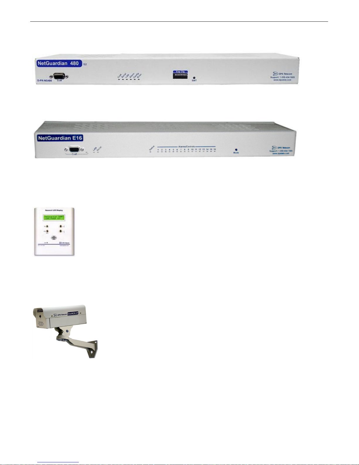
General LCD Display (GLD)
D-PK-GLDRJ-12001.00001
The General LCD Display (GLD) is a small wall-mou nted remote termin al fo r the NetGuardia n. The LCD
display shows system status and a larm messages, and th e bui lt-in spe aker giv es an audible no t ice of
ala rms. Up to 1 2 GL Ds can be daisy-cha ined off th e NetG uardi an.
NetGuardia n Si teMON IP D-PK-CAMRA
The NetGuardi an Sit eMON provides security surveil lance o f remote sites. The SiteMON con nects to
either th e NetG uardi an's inte grated 10/ 100BaseT switch or a separate 1 0/100/10 00 switch. Site MON
images can be accessed d irectly f rom the Sit eMON 's Web Browser Inte rf ace or T/GFX. You can also
mount t he camera at harsh weather site s with t he wide-temp chassis design.
Page 13
Hinged W i re-Wrap Bac k Panel
For 19" ra ck: D-PK-NGPAN-12002 For 23" ra ck: D-PK-NGPAN-12006
The hinged wire-wrap b ack pan el provides wire-wrap con nection s for t he NetGua rdian's alarms and
control relays.
Plugga b l e Barrier Panel
For 19" ra ck: D-PK-NGPAN-12021 For 23" ra ck: D-PK-NGPAN-12007
The pluggab le barrier p anel provides screw-lug barrie r plug connections for th e NetG uardi an's alarms
and con t rol relays.
8
Hinged Amphenol Back Panel
For 19" ra ck: D-PK-NGPAN-12027
The Hinged Amph en ol Back Panel easily allow s f or Upgrades fr om a KDA864 to a NetGuardian
864.
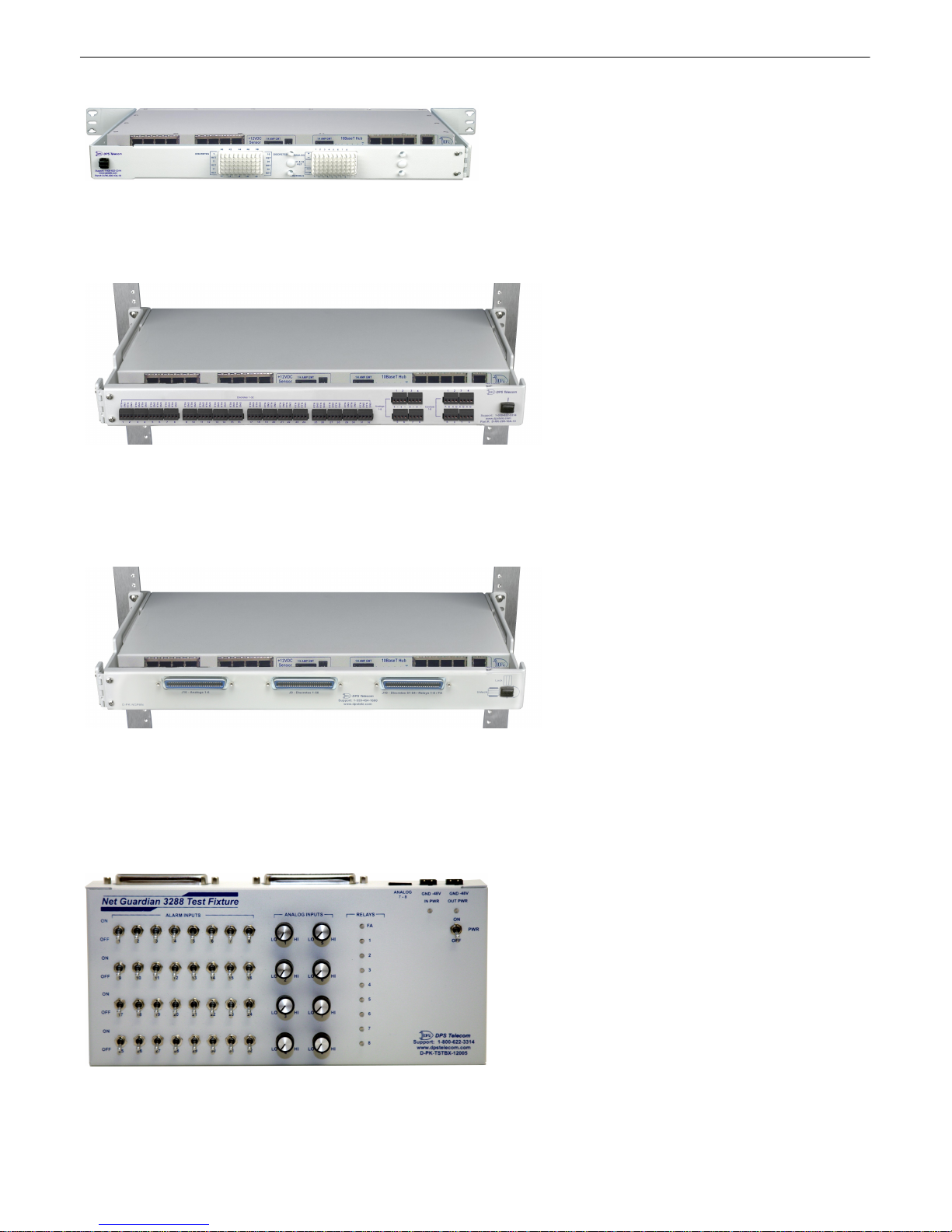
NetGuardia n 3288 Test Fixture
D-PK-TSTBX-12005.00001
Page 14

9
Every DPS product is rigo rously tested before shi pping, and th e NetG uardi an Te st Box allows
techni cia ns to ve rify e very discrete a larm input, control rel ay, and volt age-b ased an alog alarm in put on a
NetG uardi an G5. Th is time-tested t ool i s no w a vailab le to you as the NetGuardia n 3288 Te st Fi xture
(known casuall y as the "NetG uardi an Te st Box"). With 32 di screte a larm toggles, 8 a nalog knobs, and 8
control relay LEDs, yo u can ve rify every alarm input and control output o n your N etGuardians in a
control led wa y.
Page 15

Specifications5
Discrete A l arm Inputs: 32 (e xpanda ble to 80, 128, or 176 in G5 model)
64 (e xpanda ble to 112, 160, or 2 08 in 864A model)
Analog Ala rms: 8
Analog I np u t Ra n g e: (–94 t o 94 VDC or 4 to 20 mA)
Analog Accuracy: +/- 1% of A nal og Range (See Analog Step Sizes)
Control Relays: 8 Form C (ex pandabl e to 1 6, 24, 32)
Maximum V o l tage: 60 VDC/120 VAC
Maximum Current: 1 Amp, AC/DC
Ping A larms: 32
Protocols: SNMPv1, SN MPv2 c, SNMPv3, DCPx, DCPf, TRIP, SNPP
SM T P, TA P, HTT P, FTP, TELNET, ICMP, RADI U S, (SSH, HT TPS
with Hardware Accelera t ion b uild option).
Interfaces: 9 RJ4 5 Yost serial ports (17 RJ45 p orts with th e 16S top board
option)
2 RJ4 5 10/ 100 full-dupl ex Etherne t ports (1 port tie d int ernal ly to
switch
- if switch opt ion is purchased)
1 RJ1 1 tel co j ack
2 50 -pin amphenol conn ectors (discretes, controls, and an alogs)
1 4-p in screw connector (analo gs)
With Fiber top -board build op t ion: 4 10/1 00/ 1000 copper Ethern et
ports AND 2- 1000 Ba se-X SFP Fibe r ports
With D-Wire top-boa rd buil d optio n: 1 RJ11 D-Wire port
With WAN top -board build op t ion: 1 Rj45 WAN port
Physical Dimensions: 1 . 720" H x 17. 026" W x 8. 136"D (Ne t Guardian 83 2A)
(11.250"D with hinged Wire Wrap A dapt er)
1.720"H x 17.026"W x 9.636"D (N etG uardi an 864A)
(12.750"D with hinged Wire Wrap A dapt er)
Weight: 4 lb s. 3 oz. (1.9 kg)
Mounting: 19" or 23" ra ck
Power Input
Volta g e Options I n clude: –48 VDC nomin al (–3 6 to – 72 VDC)
(Optional) –24 VDC nominal (– 18 to –36 VDC)
(Optional) Wide Ra nge –24/–48 VDC (–18 to –58 VDC)
(Optional) +24V DC (+18 t o +36 VDC)
(Optional) +12V DC (+11 t o +18 VDC)
Current Draw : 300 mA at 48 VDC (1 60 0 mA a t 24 VDC)
GMT Fuse: 3/4 amp recommended
Sensor Power Output
Volta g e Output Options : +12 VDC
10
Page 16

11
+24 VDC
Output Current: Up to 2 50 mA at ei t her +12 or +24 VDC
Input Current Draw : May in crea se b y 150 mA a t 48 VDC
GMT Fuse: 3/4 amp re commende d
Modem: 33.6 K int ernal
V i sual I n terface: LCD display
16 b icolor L EDs
5 un icolor L EDs (10 wi t h Switch Optio n)
Audible Notifica ti on : A larm speak er
Operating Temperature: 32° to 140° F (0° to 60° C)
Storage Temp erature: -22° to 176° F (-30° t o 80° C)
Indus trial Temperature Option: -22° to 158° F (-30° t o 70° C)
Operating Humidity: 0%– 95% n oncond ensing
MTBF: 60 years
Windows Com p atibility: Windows 95, 9 8, NT, ME, X P, 2000 , Vista, 7 3 2/64 bit
*RoHS 5 Approved
Note: Th is equi pment ha s be en te sted and f ound to comply with the li mits for a Class A d igital device,
pursuant to part 15 of the FCC Rule s. Th ese limits are designed to provide reasona ble p rotectio n
aga inst harmful interfere nce when the equip men t is opera t ed in a commercial environmen t . This
equ ipment gene rates, uses, and can rad iate radio frequency energ y and, if not installed an d used i n
accordance with the instruction man ual, may cause harmful interfere nce to rad io communicatio ns.
Operation of thi s eq uipmen t in a re sid enti al are a is likely to cause h armful in t erfere nce in whi ch case the
user will be require d to correct th e interfere nce at hi s own exp ense.
Page 17
Hardware Installation6
Tools Needed6.1
To install t he NetGuardian, you'll need the f ollowing t ools:
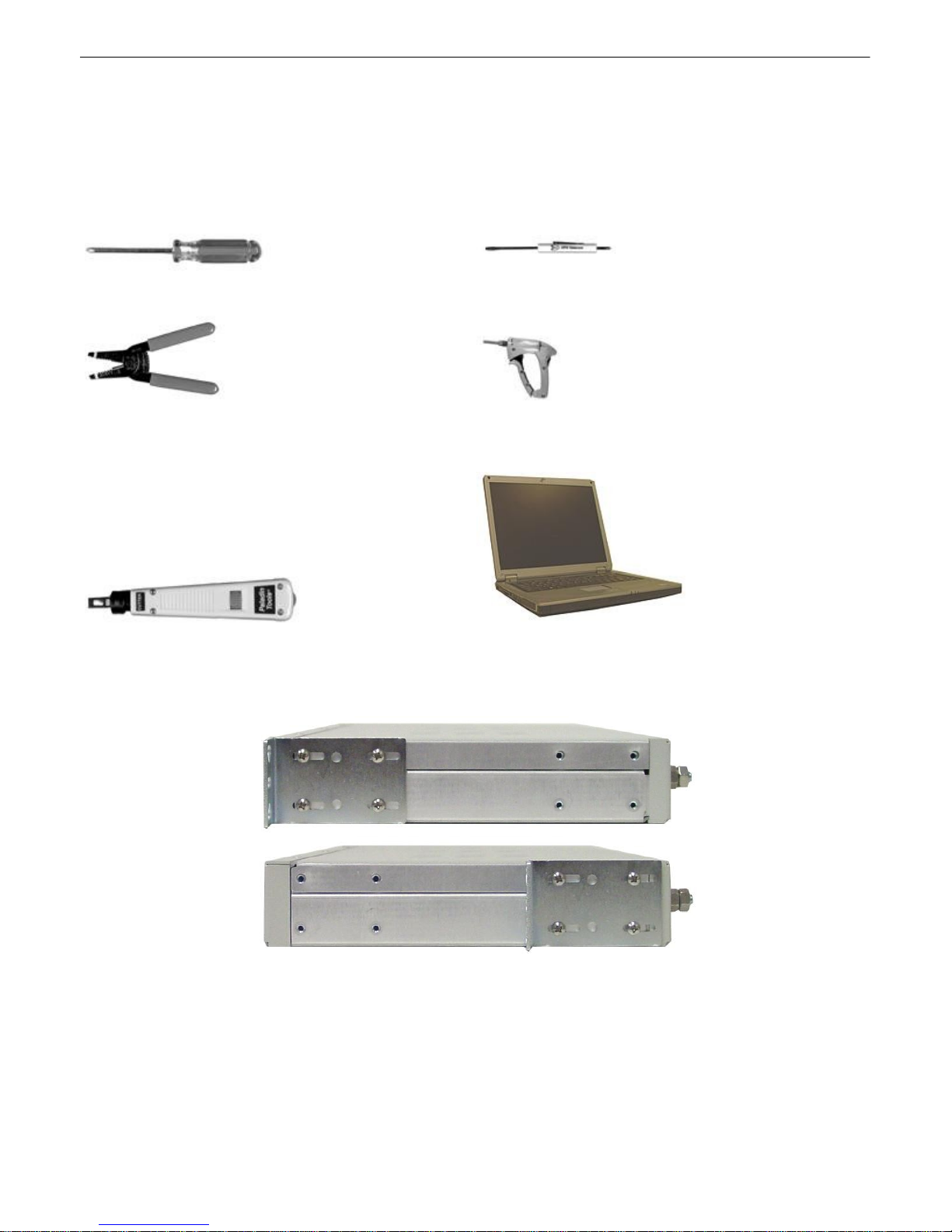
Phillip s No. 2 Sc rewdriver Small Standa rd No. 2 Screwdriver
Wire Strippers/Cutter Wire Wrap Gun (if h i n g ed w i re wrap p anel is
used)
12
Punch Down Tool (if 66 bloc ks are used) PC with NGEditG5 s o ftware
Mounting6.2
Fig. 6 . 2.1. T he NetGua rdian can be f lush or re ar-mounte d
The NetGuardi an moun t s in a 19" rack or a 23" ra ck using the pro vided ra ck ears for ea ch size. Two
rack ea r locations are provi ded. Attach the app ropriate rack ears in the flush-mount o r rear-mount
locati ons shown in F igure 6.2.1.
Note: Rack e ars can be rot ated 90° fo r wa ll mount ing or 180 º for othe r mou nting opt ions (not sho wn ).
Page 18
13
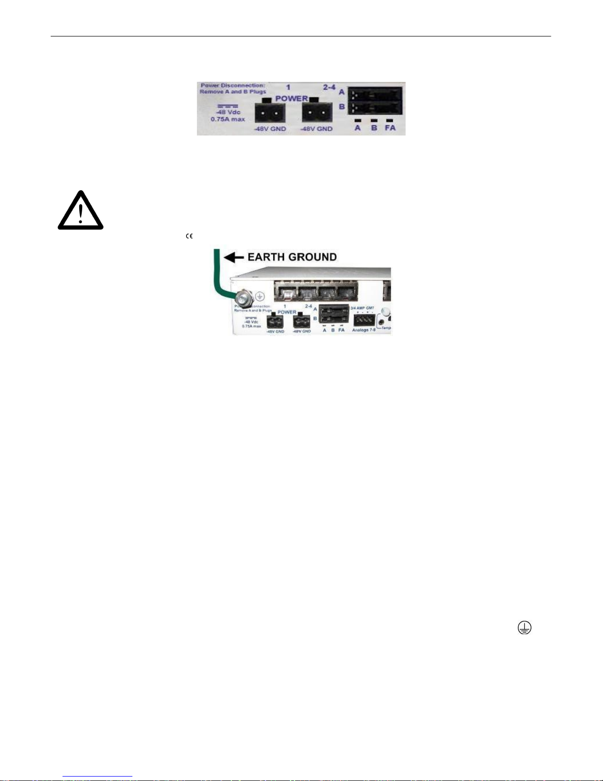
WARNING!
The Grounding Lug o n th e bac k of the unit provides a perma n ent con n ection to
earth ground w h en con n ected. The Grounding Lu g must be used in order to
com ply with standards.
Grounding Lug and Sym bol
Power Connection6.3
Fig. 6 . 3.1. Power conne ctors an d fuse.
The NetGuardi an has two screw terminal ba rrier plug p ower connectors, located on th e left sid e of the
back p anel. (See F igure 6.3. 1.)
Before y o u connect a power supply to the NetGuardian, test the voltage of y o u r po wer supply:
· Connect the b lack common lead of a voltmeter to t he ground termina l of the ba t t ery, and connect
the re d l ea d of the v ol t mete r to th e ba tte ry 's –48 V DC termin al . The v ol t mete r shoul d rea d
between -36 and –7 2 VDC. I f t he readin g is outsid e this ran ge, test the p ower suppl y.
· I f yo u r N e tGuardia n h as the -24 VDC power conn e ctio n op t io n , th e n th e vo l tmete r shou ld rea d
between -18 and -36 VDC.
· I f yo u r N e tGuardia n h as the +12 VDC power conne ctio n op ti o n, the n the v o lt o meter shou l d re ad
between +11 a n d +18 VDC.
To connect the NetGuardian to a p o wer supply, follow these steps:
1. Remove th e fuse from the ba ck pan el of the N et G ua rd ia n. Do not reinsert the fuse until al l
connection s to the unit have been made.
2. Remove t he power conne ctor plug from Power Con nector A. Note tha t t he pl ug can b e inserted
into the power conn ector only one way - this en sure s that the barri er plug can o nly be rei nserted
with the correct polari ty.
Note: that the –48V terminal i s on the left and the GND terminal is o n th e right.
3. Use th e gro u nd i n g lu g to conne ct the un i t to ea rt h gro u n d. Th e g ro un d i n g lu g is nex t to th e
symbol. Insert the eyelet o f t he ea rt h ground cable between t he two bolts on the groundin g lug
(Gro und cab le no t includ ed).
4. Insert a battery ground int o the power con nector plug 's right terminal and t ighten th e screw
5. Insert a –48 VDC line to the plug's left term inal and tighten its screw.
Page 19

6. Push the power connector pl ug fi rmly back i nto the po we r con nector. If the power fe ed is
WARNING!
The Grounding Lug o n th e bac k of the unit provides a perma n ent con n ection to
earth ground w h en con n ected. The Grounding Lu g must be used in order to
com ply with standards.
Grounding Lug and Sym bol
connected correctly, the LED by the conne ctor will li gh t GREEN. I f t he po larit y of the power feed
is reve rsed , t he LED will no t illuminate .
7. Repeat Steps 2–4 fo r Power Connector B.
8. Reinsert th e fuse to po wer th e N e tGuardia n . The fro nt pan e l LEDs will flash RED and GREEN.
To connect the NetGuardian to a p o wer supply using a WA GO conn ector, fol l o w these steps:
14
1. Remove the 2 fuses (A& B) from the ba ck pan el of the N etG u ard ia n. Do not reinsert the fuses until
all c o n n ection s to the unit have been made.
2. Remov e the WA GO powe r con nector. Note tha t t he pl ug can b e inserted in t o the power conn ector
onl y one way — t his ensures tha t t he barrier p lug can only be reinserte d with t he correct polarit y. Note
that the –4 8V termin al is on Slots 1 and 3 and the GND termin al is on Slots 2 and 4 when cou ntin g
from left t o right.
3. Use the gro u n di n g lu g to conn ect the un i t to e a rth gro u n d . Th e gro u nd i n g lu g is nex t to the
symbol.Insert the eyelet o f t he ea rt h ground cable between t he two bolts on the groundin g lug (Gro und
cable not i ncluded).
4. Insert a battery ground into the power connector plu g's slots 2 and 4 by pushi ng down on t op of t he
app ropriate slot of the WAGO conn ector with a screwdri ver and inserting the wi re int o the slo t , t hen
rele asing the screwdrive r. Insert a –48 VDC line to the plug's slots 1 and 3 using the same method a s
before.
Page 20
15
Inserting a -48 VDC Line i nto Sl ot
1 of WAGO Connector
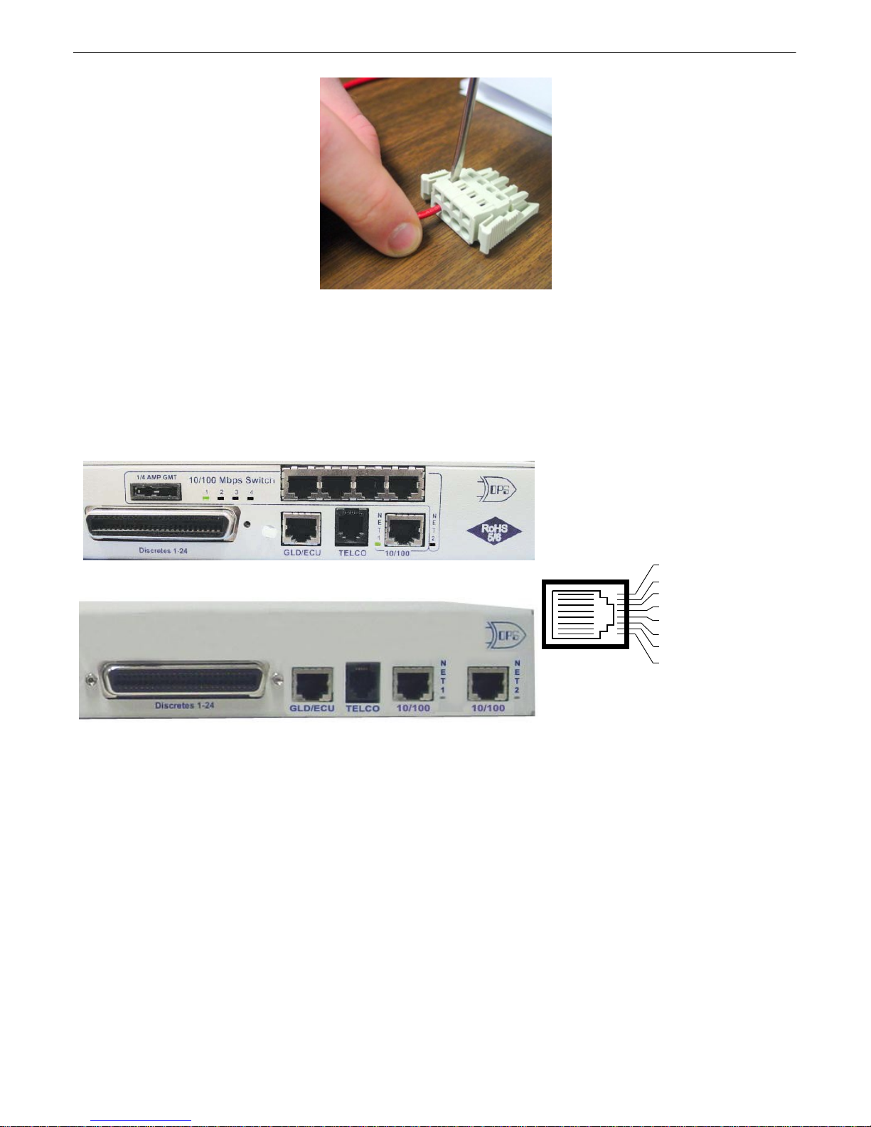
Fig. 6 . 4.1. T wo 10/1 00 Ethernet ports (With Switch)
Fig. 6 . 4.2. T wo 10/1 00 Ethernet ports (Without Swi t ch)
RJ45 Et herne t Co nnection
8
7
5
6 Receive In – (RI–)
4
3 Receive In + (RI+)
2 Transmit Out – (TO–)
1 T ransm it O ut + (T O+)
Fig. 6 . 4.3 Etherne t port p inou t
5. Push the power conne cto r plug f irmly ba ck into t he po we r con nector. If the power fe ed is connected
correctly, the LED by the conn ector will ligh t GREEN. If t he po larit y of the power feed is rev ersed, th e
LED will not i lluminate.
6. Rein sert the fu ses to power the N e tGuardia n . Th e fro n t pa n el LEDs will fla sh RED and GREEN.
LAN Connec tion6.4
For enhanced security, t he NetGua rdian G5 has two 10 / 100 Ethernet po rts. Ea ch p ort has its own
separat e IP address and subn et, so you can safe ly conn ect one port to your private company L AN and
the othe r t o the public I ntern et.
There is no ro uting bet we en Net 1 and Net 2, th is ensures that both con nections are independe nt of
each other. By d efau lt, ou t bound da t a traff ic from the NetGuardian 832A wi ll be sent over Net 2. Only
outbound da t a tha t is specifically directed to Net 1, usually t he Company's LAN, will be sent t o Net 1. To
use bot h net wo rk interfaces, be sure Net1 and Net2 are on sep arate Subnet Masks.
To use o nly one o f t he network inte rf aces, set e ither Net1 or Net2 to IP add ress being u sed and set the
unu sed network IP subnet an d gateway t o 255 . 255.255 . 0. If your NetGuardian ha s the 4-port hub build
opti o n , u se N et 2 , whi ch is connected to the H u b . Both po rt s are stand ard RJ4 5 po rt s that ta k e standard
RJ45 Ethe rn et cable s. I f the IP conne ctio n i s OK, the LN K LED will lig h t SOLID GREEN when t he cabl e
is connected .
Page 21
The NetGuardi an G5 un it with t he in t egrat ed switch comes with t wo physical 10/1 00 Ethernet ports. The
standa rd G5 uni t wi t hout t he switch comes equipped with two physical E t herne t ports. The switch is
internally t ied t o NET 2 and any one of it s four port s can be used fo r uplink.
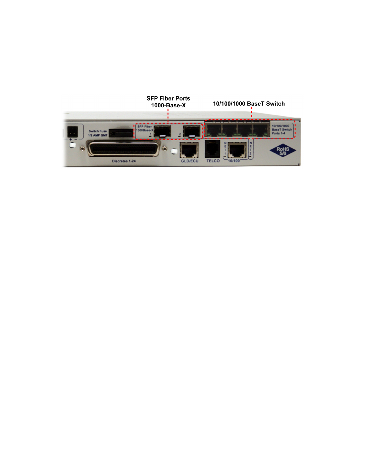
Build Opti on: NetGuardian G 5 with G i gE Fiber Top Board
If your NetGuardian G5 was ordere d with t he G igE Fiber top bo ard, 1 000Ba se SFP inte rf ace must be
used. The SFP p orts are in t ernally con nected t o the 4 port switch and NET 2.
Fig. 6 . 4.4. Back panel o f Ne t Gu ardia n G5 with fiber
16
Page 22
17
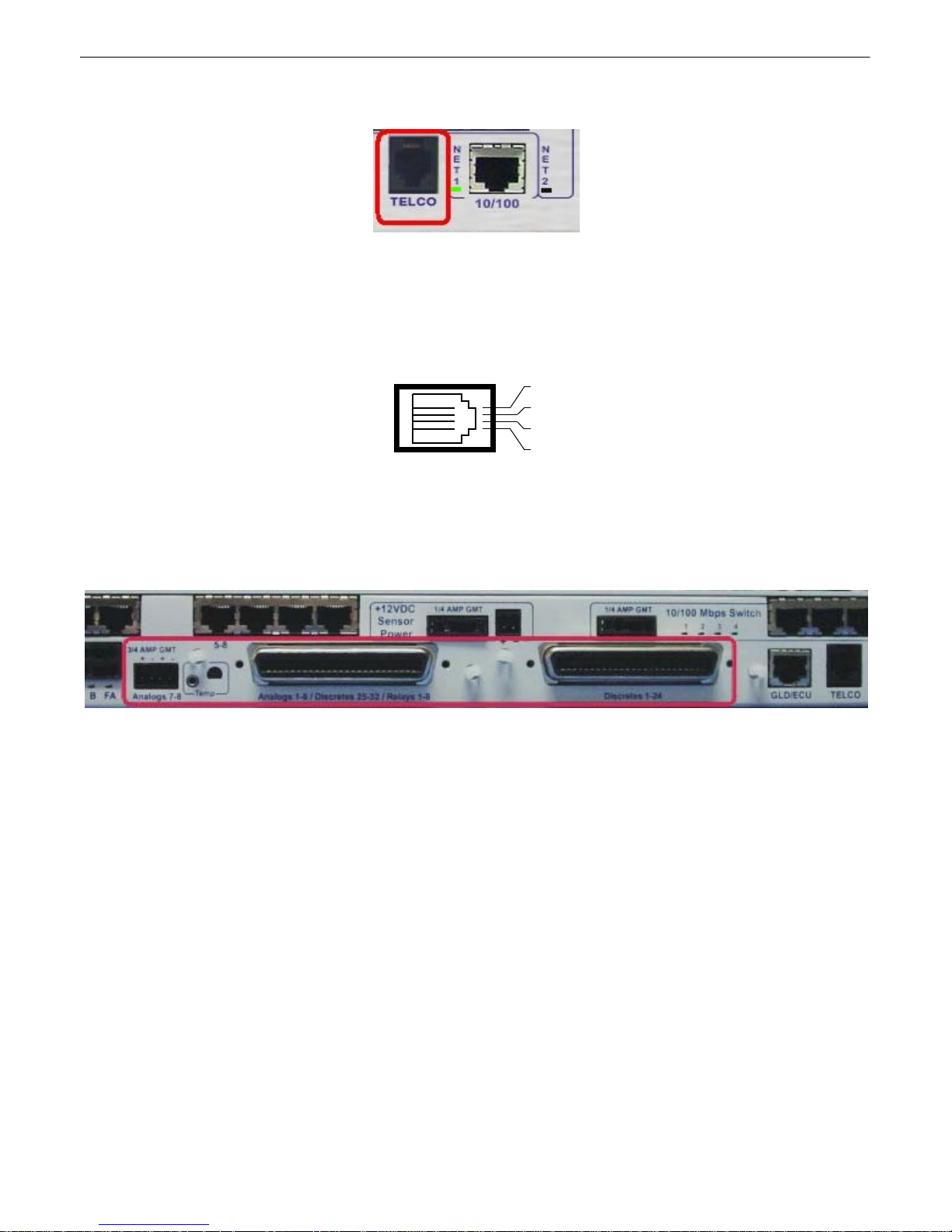
Telco Connection6.5
Fig. 6.5.1. Telco jack
The rear panel t elco ja ck (see F igure 6.5.1) connects the NetGuardi an internal mode m to a standa rd
pho ne line for dial-up access and pager alarm not ificati on.
RJ11 Phone Line Connection
4
3 Ring
2 Tip
1
Fig. 6 . 5.2 Telco jack pinout
The pinout fo r t he Te lco jack is shown i n Fig ure 6.5.2, above.
Alarm a n d Con trol Relay Connec tions6.6
Fig. 6.6.1. Alarm and control relay connectors
The NetGuardi an G5's discrete alarm inpu t s, control rel ay o utput s, and fi rst six anal og alarm inputs are
connected thro ugh the two 50-pi n connectors labeled "Discretes 1–24" and "Analog s 1– 6/Discretes 25–
32/Re lay s 1– 8" on t he back pan el. Analog alarm input s 7 a nd 8 are connected th rough the f our-pin
connector labeled "Anal ogs 7–8 . " (See Figure 6.6. 1.)
Note: The N etGuardian's 864 A's discrete alarm inputs, contro l rela y output s, and first six analog a larm
inp uts are conn ected through the t wo 50-pi n conne ctors la bele d "Discretes 1–4 8" an d "Analog s 1– 6/
Discretes 49–64/Relays 1–8 " on t he ba ck panel. Analog ala rm in puts 7 and 8 a re conne cted thro ugh the
four-p in conne ctor labele d "A nal ogs 7–8."
Page 23
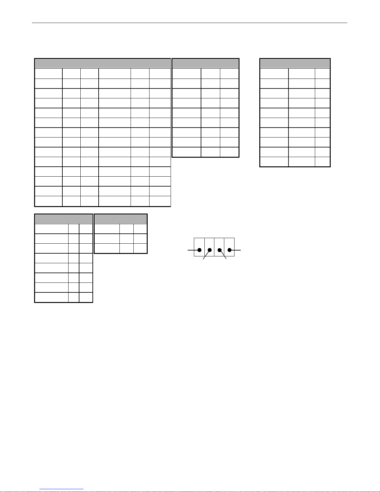
6.6.1 Al arm and Control R elay Connector Pinout Table (832A)
Discretes 1–25
RTN
ALM
RTN
ALM
ALM 1
126ALM 13
1338ALM 2
227ALM 14
1439ALM 3
328ALM 15
1540ALM 4
429ALM 16
1641ALM 5
530ALM 17
1742ALM 6
631ALM 18
1843ALM 7
732ALM 19
1944ALM 8
833ALM 20
2045ALM 9
934ALM 21
2146ALM 10
1035ALM 22
2247ALM 11
1136ALM 23
2348ALM 12
1237ALM 24
24
49
GND
25
50
Discretes 25–32
RTN
ALM
ALM 25
126ALM 26
227ALM 27
328ALM 28
429ALM 29
530ALM 30
631ALM 31
732ALM 32
833Control Relays 1–8
NO/NC
CO
CTRL 1
934CTRL 2
10
35
CTRL 3
11
36
CTRL 4
12
37
CTRL 5
13
38
CTRL 6
14
39
CTRL 7
15
40
CTRL 8
1641FUSE
1742Analog s 1–6
ADC
+–ADC 1
1944ADC 2
2045ADC 3
2146ADC 4**
2247ADC 5**
2348ADC 6**
2449GND
2550Analog s 7–8
ADC
–+7
7–
7+
8**
8–
8+
A nalogs 7–8
ANA 7 – ANA 8 +
ANA 7 + ANA 8 –
18
Table 6.6.1.A. Alarm and con t rol relay connector p inout for G5
Table 6. 6.1.A shows the pinouts for th e 50-pin con nectors "Discretes 1–24 " and "Analog s 1– 6/Discretes
25– 32/Relays 1– 8," a nd the pinout f or the f our-pi n conne ctor "A nalogs 7–8. "
Note that th e N etGuardian's control relays can be set for eit her Normally Open or N ormally Cl osed
ope ratio n. By factory d efault, all contro l relays are set to N ormally Open. You can reset a ll relays for
Normally Closed o perat ion a t t he hardware lev el by resetti ng a j umper on t he NetGuardian circuit bo ard.
Y ou can a lso configure th e control relays individually, using e ither t he Web in t erface or the NGEditG5
software utility.
For instructions on resetting control rela ys for Normall y Closed opera t ion, see t he section t itle d
"Controls."
ADC** chann els 4, 5, 6, and 8 may be un ava ilab le fo r exte rnal use. These a nalog channels are
sometimes conf igure d in hardware for monitoring A and B po we r f eeds, internal te mpe rature, and
ext ernal tempera t ure. For details reg ardin g yo ur uni t 's hardware, plea se re f erence the product
description appen dix .
Page 24

19
Discretes 1–48
ALM
PIN
ALM
PIN1262613212739327281442294052830156331417293216843342930341710535431131361812637441332381914739451533402016841461734422118943471935442220104548213646232211474923374824
2412GND
25
Discretes 49-64, Rela ys 1-8, Anal ogs 1-6
ALM
PIN
Relays 1-8
4926RLY 1
934501RLY 2
10355127RLY 3
1136522RLY 4
12375328RLY 5
1338543RLY 6
14395529RLY 7
1540564RLY 8
16415730FUSE
1742585ADC
+-5931ADC 1
1944606ADC 2
20456132ADC 3
2146627ADC 4**
22476333ADC 5**
2348648ADC 6**
24
49
GND
25
GND/RTN*
50
Analog s 7-8
ADC+-7BA8**BA
6.6.2 Al arm and Control R elay Connector Pinout Table (864A)
Table 7.B. Al arm and relay connection pi nout s for Ne t Guardia n G5 864
RTN* is the a larm return pin. Alarms on standa rd units are dry closure or groun d closure. Most uni t s will
have RTN interna lly t ied t o GND. However, special ha rdware a ssemblie s may h ave RTN isolate d from
GND. For details regarding your unit's hardwa re, pl ease refe rence the prod uct descriptio n append ix.
ADC** chann els 4, 5, 6, and 8 may be un ava ilab le fo r exte rnal use. These a nalog channels are
sometimes conf igure d in hardware for monitoring A and B po we r f eeds, internal te mpe rature, and
ext ernal tempera t ure. For details reg ardin g yo ur uni t 's hardware, plea se re f erence the product
description appen dix .
Page 25

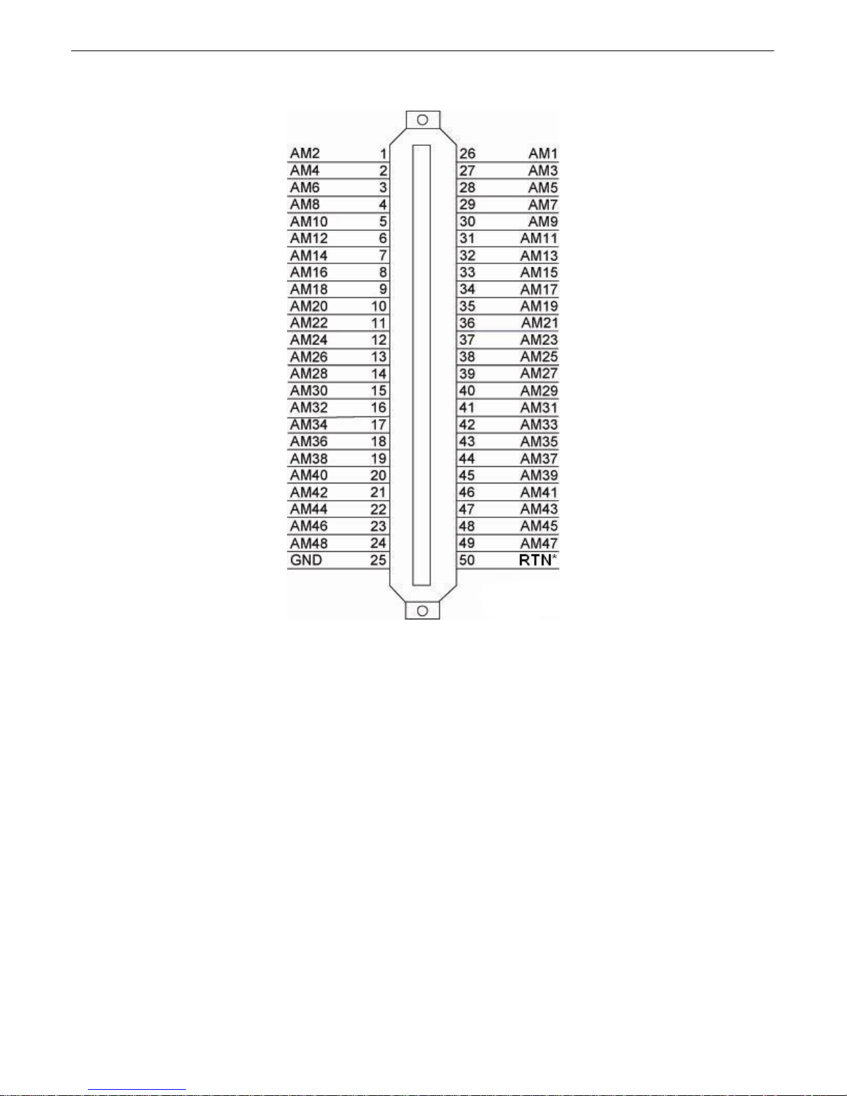
6.6.3 Discretes 1–24 Connector Pinout Diagram (832A)
20
RTN 1
RTN 2
RTN 3
RTN 4
RTN 5
RTN 6
RTN 7
RTN 8
RTN 9
RTN 10
RTN 11
RTN 12
RTN 13
RTN 14
RTN 15
RTN 16
RTN 17 ALM 17
RTN 18
RTN 19
RTN 20
RTN 21
RTN 22
RTN 23
RTN 24
GND
1
2
3
4
5
6
7
8
9
10
11
12
13
14
15
16
17
18
19
20
21
22
23
24
25
26
27
28
29
30
31
32
33
34
35
36
37
38
39
40
41
42
43
44
45
46
47
48
49
50
ALM 1
ALM 2
ALM 3
ALM 4
ALM 5
ALM 6
ALM 7
ALM 8
ALM 9
ALM 10
ALM 11
ALM 12
ALM 13
ALM 14
ALM 15
ALM 16
ALM 18
ALM 19
ALM 20
ALM 21
ALM 22
ALM 23
ALM 24
GND
Fig. 6.6.2.1. Pinout Diagram for Discretes 1–24 conne ctor
Page 26

21
6.6.4 Analogs1–6/Discretes 25–32/R elays 1–8 Connector Pinout
Diagram (832A)
RTN 25
RTN 26
RTN 27
RTN 28
RTN 29
RTN 30
RTN 31
RTN 32
CTRL 1 NO
CTRL 2 NO
CTRL 3 NO
CTRL 4 NO
CTRL 5 NO
CTRL 6 NO
CTRL 7 NO
CTRL 8 NO
FUSE NO FUSE CO
Unused
ANA 1 +
ANA 2 +
ANA 3 +
ANA 4 +
ANA 5 +
ANA 6 +
GND
1
2
3
4
5
6
7
8
9
10
11
12
13
14
15
16
17
18
19
20
21
22
23
24
25
26
27
28
29
30
31
32
33
34
35
36
37
38
39
40
41
42
43
44
45
46
47
48
49
50
ALM 25
ALM 26
ALM 27
ALM 28
ALM 29
ALM 30
ALM 31
ALM 32
CTRL 1 CO
CTRL 2 CO
CTRL 3 CO
CTRL 4 CO
CTRL 5 CO
CTRL 6 CO
CTRL 7 CO
CTRL 8 CO
Unused
ANA 1 –
ANA 2 –
ANA 3 –
ANA 4 –
ANA 5 –
ANA 6 –
GND
Fig. 6.6.3.1. Pinout Diagram for Discretes 25–32/Relays 1–8 conn ector
Page 27
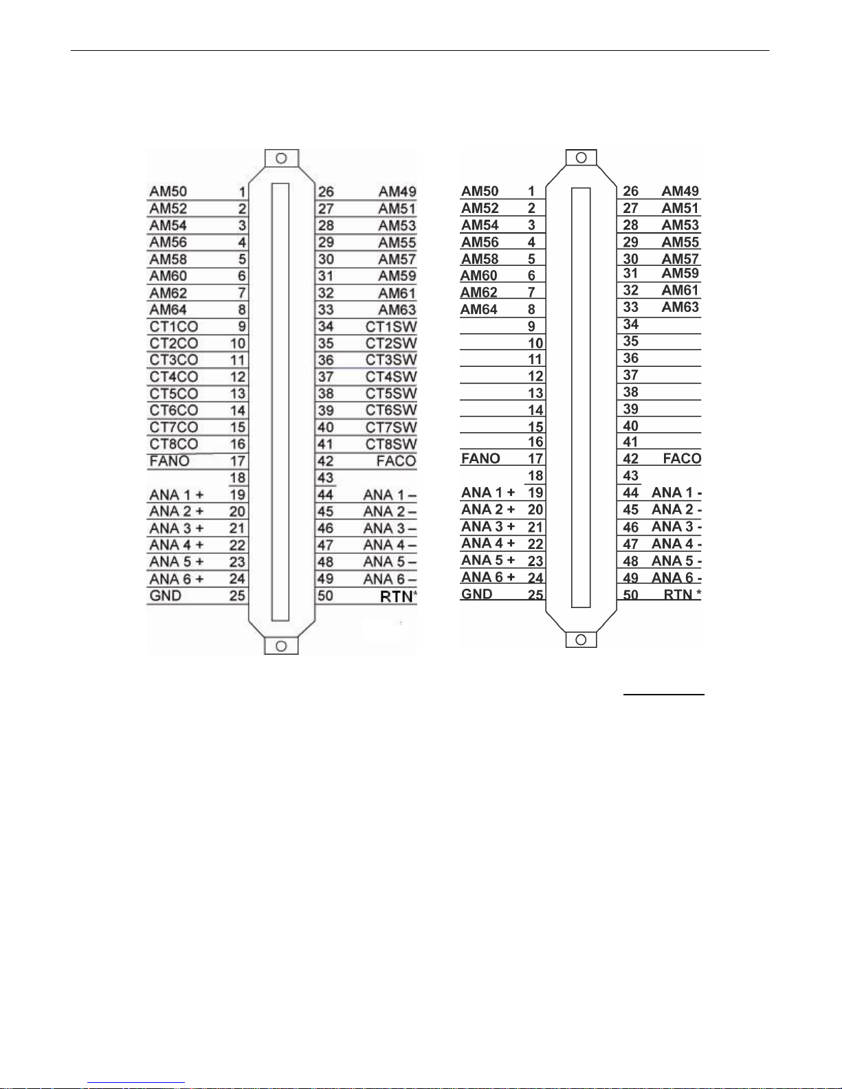
6.6.5 Discretes 1- 48 Connector Pinout Diagram (864A)
22
Fig. 6. 6.5. 1- Pinout Diagram for Discretes 1-48 Connector
RTN* is the a larm return pin. St anda rd configurations ha ve this pin t ied t o GND. While it is possible to
change thi s confi guration t o utilize di f f erent t ypes of ala rms (i.e. T T L, Open Co llector, Battery Closure),
the ha rd ware must be ordere d in tha t confi gu rat io n. I t is NOT field-adjustable.
.
Page 28
23
Fig. 6. 6.5. 2- Pinout Diagram for Analogs 1-6/
Discretes 49-64/Relays 1-8 Connector
Fig. 6. 6.5. 2- Pinout Diagram for Analogs 1-
6/Discretes 49-64. This pinout only applies
to the NetGuardian 864A G5 wit hout relays.
See note below.
6.6.6 Analogs 1-6/Discretes 49-64/Relays 1-8 Connector Pinout Diagram
(864A)
RTN* is the a larm return pin. St anda rd configurations ha ve this pin t ied t o GND. While it is possible to
change thi s confi guration t o utilize di f f erent t ypes of ala rms (i.e. T T L, Open Co llector, Battery Closure),
the ha rd ware must be ordere d in tha t confi gu rat io n. I t is NOT field-adjustable.
Note: Figure 6.6.5 . 2 is a special pino ut for a particular b uild of the NetG uardi an 864A G5 with out control
rela y s. It on ly ap pl ie s to the foll owi ng part nu mber: D-PK-NG864-12022.00001
Page 29
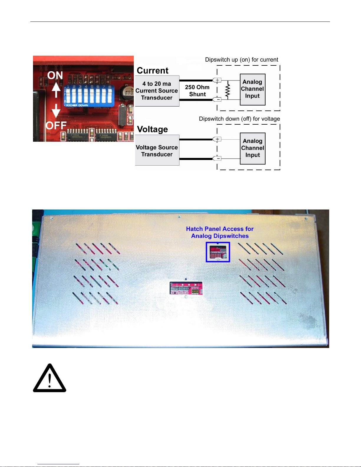
6.6.7 Analog Dipswitches
You can acces s t he analog dipswitc hes via the sliding hatch panel on top of the unit
The analogs are con t rolled by the dipswitches accessibl e via the top sli ding panel. For milliamp sensor
ope ratio n (current l oop), t urn the dipswitch on by placing it in th e up (ON) position. F or vo ltage
ope ratio n, place the dipswitch in t he down (OFF) position.
24
WARNING: Do not put the dipswit ches in the upward, O N position (current l oop mode)
unless you are sure of the analog setting. Having the dipswitch on puts a 250 ohm
resistor across the input li nes. Any voltage beyond 5V or 20 mA will damage
components.
Page 30
25
Se nsor Function
Analog I nput
Internal Temperature
analog input 4
Power Feed A
analog input 5
Power Feed B
analog input 6
Ext ernal Temperature
analog input 8
Analog Step Si z es and Accuracy
Input Vol ta ge Rang e
Resolution (Step Si z e)
Accuracy
0-5 V
.0015 V
+/- .05V
5-14 V
.0038 V
+/- .14V
14-30 V
.0081 V
+/- .30V
30-70 V
.0182 V
+/-.70V
70-90 V
.0231 V
+/-.90V
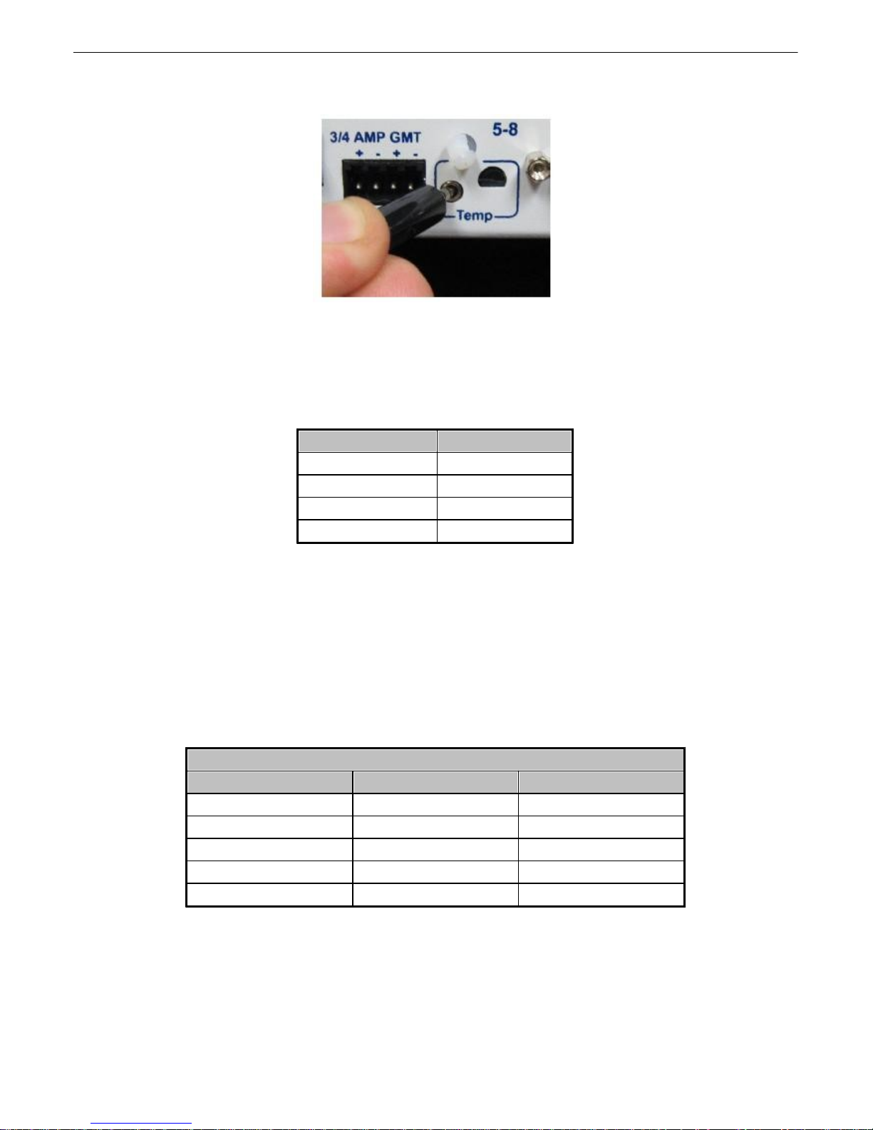
6.6.8 Integrated Temperature and Battery Sensor (Optional)
Fig. 6.6.6.1. The e xternal t emperatu re sensor
The opti onal inte grated temperature and batte ry sensor monit ors the ambi ent temperatu re and the
NetG uardi an's power i nputs. Th is option is av ailable only if it was ordered with your N etGuardian. T he
integrat ed tempe rature sen sor measure s a ra nge of 32° F t o 140° F (0° C to 60° C) with in an accuracy
of ± 1°.
Table 6.6 . 6.A. Integrat ed sensor an alog chann els
Y our integrated sen sors each o ccupy one of the unit 's 8 analo g chann els. Table 6. 6.6.A lists the an alog
channels used fo r t he in t egrat ed temperature and batt ery sensor. Note that these opti ons are factory
pre-set, based o n your build o ptio ns and cannot be adjusted.
6.6.8.1 Analog Step Sizes
Analog Step Sizes:
Y our Analog s are accurat e to wit hin +/- 1 % of th e analog range.
Table 2.J . Analo g step sizes and accuracy
Page 31

Data Ports6.7
Location of Pin 1 on RJ-45
Connector
Fig. 6.7.1. Data ports 1– 8
The NetGuardi an's eight dat a port s pro vide reach-through termin al server functionality f or conne cting
multip le simultan eo us users to extern al equ i pment vi a Tel n et ov e r LA N. Each port can fu nction as a
proxy connection t o an exte rnal device, a craft p ort, a channel port, a TCP or UDP reach-throug h port.
The NetGuardi an can support simulta neous proxy conne ctions for up t o eight u sers.
NOTE: See Section 6.8.6 if you ha ve the 16S serial port b uild opti on
26
Yost RS-232 R J45 Con nector
8 RTS (Request to Send)
7 DTR (Data Terminal Ready )
6 TX D (Tr ansmit Data)
5 GND (Ground)
4 GND (Ground)
3 RXD (Receiv e Data)
2 DSR (Data Set Ready)
1 CTS (Clear to Send)
Yost 4-Wire 202 Connector
Fig. 6.7.2 Data port pinouts
Yost RS-485 R J45 Con nector
8 TX - (T ransmit -)
7 N/C (Not Connected)
6 RX- (Receive -)
5 GND (Ground)
4 GND (Ground)
3 RX+ (Receive +)
2 N/C (Not Connected)
1 TX + (T r ansmit +)
8 TX + (T r ansmit +)
7 N/C (Not Connected)
6 RX- (Receive -)
5 GND (Ground)
4 GND (Ground)
3 RX+ (Receive +)
2 N/C (Not Connected)
1 TX - (T ransmit -)
NetG uardi an data ports can be conf igure d for Yost RS-232, RS-48 5, an d 4-wire 202 RJ45 con nects.
These d ata p orts are availabl e as optiona l builds on NetGuardi an hardware unit s (Call DPS Sales for
Page 32

27
GLD/ECU Port
Data Po rt Pinout
more inf ormation @ 1-8 00-69 3-0351). Th e pinouts for Da t a Ports 1–8 are shown in Fi gure 6 . 7.2, above.
DB9 RS-232
GND
RTS
RX
TX
12345
6789
CTS
Pin # Signal Description
1 Not connected
2 TX Transmit data
3
RX
4
5 GND Ground
6 Not connected
7
CTS Clear to send
8
RTS
9 Not connected
Recieve Data
Not connected
Request to send
Fig. 6.7.2 DB9 RS-23 2 Pino uts (Craft Port Only)
6.7.1 Connecting NetGuardian Accessories
Some N etG uardi an accessories must be con nected to part icular data p orts. Ho we ver, if you do n't use
these accessorie s, the da ta po rts are av ai la b le for oth er uses.
I f y ou are using a N et G u ard i an Exp a n sion , conne ct it to Port 7.
6.7.2 GLD/ECU Expansion Port (R S-485)
If you are using a General LCD Display (GLD) unit, con nect it to the GLD/ECU port.
Hardware Options6.8
The NetGuardian G5 series has a number of additional hardware options that you may have specif ied when you
ordered your RTU. For more information about NetGuardian hardware options that you may ha ve ordered with
yo ur NetGuard ian, see the subsections of this chapter.
Note: You must order your NetGuardian with the options contained in this chapter. You cannot add them to your
NetGuardian after it has been built and shipped.
Page 33

6.8.1 Integrated 10/100BaseT Ethernet Switch (Optional)
Fig. 6.8.1.1 NetGuardi an integrated Et herne t Swi t ch
Y ou can o rder your NetGua rdian G5 wi t h an optional integrat ed Ethernet switch, which prov ides four
regu lar Eth ernet ports. (See F igure 6.8.1.1). The integrated Et herne t switch is powered by the same –48
V DC power as the NetGu ardian, whi ch p rovi des more secure, more rob ust operation tha n switches that
run o f f commercial power. Th e integrat ed switch also fre es valuabl e rack space by eliminating an
unn ecessary extra uni t .
To pow er and ac tivate the integrated Ethernet switc h, in sert t he provided 1/4 amp fuse in the
switches fuse socket. (See Figure 6.8.1.1) If you ever want to t urn off power to the inte grate d switch,
just remov e the f use.
28
RJ45 Ethernet Conn ection
8
7
6 Trasm it Out – (TO–)
5
4
3 Transmit Ou t + (T O+)
2 Receive In – (RI–)
1 Receive In + (RI+)
Fig. 6.8.1.2. Regul ar Ethe rnet port pi nout
The f our Eth ernet ports of the switch are re gular straigh t -t hrough Eth ernet ports. (See F igure 6.8.1.1)
The pinout fo r t he regula r Et hernet port s is shown in Fig ure 6.8.1.2, above .
6.8.2 Integrated T1/E1 Port
If you ord ered your Ne t Guardia n with a T1 or E1 port, yo u can connect to yo ur N etGuardian via T 1 or E1
and pa ss LAN traff i c ove r T1/E1 or v i ce ve rsa thro ug h the NetGua rd ia n 's inte rna l switch.
Fig. 6.8. 2.1 A NetGuardian with integrated E1/T1 WAN port.
Note: Bot h the T 1/E1 port an d the 4th p ort on t he integ ra t ed switch are t ied i ntern ally to Net2. If using
the in te gra te d T1 /E1 connectio n , yo u can conve rt traf fi c to LA N only on switch po rt s 1-3 (f rom left to
Page 34

29
right).
Page 35

6.8.3 GSM/GPRS or CDMA Wireless Modem Top Board (Optional)
6.8.3.1 Wirel ess Modem A cti vati on
WARNING: Do n ot reset or power o f f t he modem du ring activat ion.
1. Set up y our wireless data a ccount t hroug h Mu lti-Te ch o r your preferred serv ice provide r.
2. Verify t hat th e ant enna is screwed onto the back pan el of t he un it.
3. Locate the Model # and ESN/MEID. These can be found on the Read Me First pag e tha t is include d
with your unit, or on t he ba ck panel of your device.
30
4. G o to th e Multi -Te ch Sup p o rt p a ge a n d o p e n th e li n k for 'Cell u l a r Modem A ctiv a t io n '
Page 36

31
www.multitech.com
5. Fo llow the in structions that are associated wi t h yo ur modem model and service provider.
Important: If yo u are having t roubl e fin ding your modem's mode l number, please contact DPS support
at 559-454-16 00.
6.8.4 +12 or +24 VDC Sensor Power Supply
Fig. 6.8.4.1. +12 VDC sensor power supply
Y ou can o rder your NetGua rdian G5 wi t h an optional +12 VDC or +24 VDC sensor power supply. (Se e
Figure 6. 8.4.1 . ) T his provide s a convenien t wa y to connect an aux ilia ry sensor to a robust batte ry power
supply, so if AC power goes down your sen sor will still be powered. . Just pl ug th e sensor into the back
pan el to use the sensor p ower supply.
The t wo -pin con nector for t he sensor power suppl y is a barrier plug conne ctor simila r t o the mai n power
connector.
To power an external s ensor, fo l l o w these steps:
1. Remove t he 1/ 4 amp fuse fro m the sensor powe r sup ply on the back pane l of the NetGuardian.
(See Figure 6.8.4. 1.) Do not reinsert the fuse until all p o wer connections to th e external
sensor have been made.
2. Remove t he power conne ctor plug from the sensor power supply . Note that the plu g can be
inserte d int o the power connector on ly o ne way — t his ensures that the barri er plu g can on ly b e
rein serted with the correct pola rity . N ot e tha t the positive term i n al is o n th e left and the
negative terminal is on th e right.
3. Connect the a pprop riate lead s to each of t he plug's screw termin als and t ight en the screws.
4. Push the po wer conn ector p lu g firmly back i nt o th e sensor po wer suppl y conn ector.
5. Reinsert t he fu se to power t he external sensor.
Page 37

6.8.5 Hardware Acceleration (SSL/SSH)
If you ord ered your Ne t Guardia n with hardware accelerat ion, t hen your NetGu ardia n is capable of SSL/
SSH con nections.
For hel p accessing you r Ne tG u a rdi an 's TTY inte rfa ce via SSH , see Establ i shing a n SSH Sessio n .
For hel p confi gu ri ng y ou r N e tGuardia n's web int erf ace for SSL (H TTPS) conn ectio n s, see the Ethernet
Ports section of the NetG uardi an Web Interface manu al.
6.8.6 Integrated 8 Additional Serial Data Ports
Y ou can o rder your NetGua rdian 832 A G5 wi t h the 16S build opti on. Th is option gi ves yo u 8 extra serial
data port s (for a tota l of 1 6 serial data ports tota l) to p rovide extra reach-thro ugh cap acity to con t rol y our
ext ernal serial dev ices.
32
Figure 6.8.6.1 Seria l Server Ports.
NOTE: Uses same pino ut as ports in 6.7
The f irst 7 serial ports can be used concurren t ly, while t he remaining 9 are pooled toget her an d can be
accessed 1 at a ti me t hroug h the T T Y interf ace or by prox y connection t o the 8th serial po rt . Co nnect
your serial devices via RS232 or RS485 and access the dev i ces through eith er through direct or i ndirect
proxy.
The 1 6S op t io n can be ord e re d wit h th e +12/+24 VDC Sensor Power Sup pl y , which pro vides a
conve nient way t o conne ct an auxiliary sen sor to a battery powe r sup ply, so i f AC power goes down
your sensor will still be powere d.. Just plug the sen sor i nto the ba ck panel to use the sen sor p ower
supply. See Section 6.8. 4 for more information abou t t he Sensor Power build opti on.
The 16 S opti o n also in clude s hardware accelerat io n (SSL/SSH). For help a ccessing yo ur
Ne tG ua rdia n's TTY int erfa ce via SSH, see Establishing a n SSH Sessi o n.
Page 38

33
6.8.7 D-W i re Sensor Inputs
The port on your NetGuard ia n labe le d D-Wire suppo rts up to 16 D -W i r e sen so r s. Your NetGuard ian
powers and communi cates with your D-Wire sensors via simple RJ-11 conne ction .
Note: The DPS Temperat ure and Humidi t y Sen sor, DPS part number D-PK-DSNSR-1200 2, occupies
two no des.
6.8.7.1 Connecting D-Wire Sensors
Using a stand ard 6P4C, straight-throu g h RJ -11 ca b l e (part number D-PR-04 5-10A-01, pinou t below),
connect the D-Wire port on the Ne tG u ard i an to the In jack on the D-Wire Sensor. Chai n additional
sensors to the D-Wire sensor (using th e same straight -th rou g h cabl e s) from the Out jack on t he
prev iou s sensor to the In ja ck on the next (i.e. Out on sensor 4 to In on sen sor 5 ).
Fig. 6.8.6.1.1 Pin out fo r t he NetGua rdian and D-Wire Sensor RJ-11 jacks
For det ai l s abou t confi gu ri ng yo u r sensors throug h th e web int erf ace see the Sensors section of this
web browser user manual.
Optional 66 Block Connector (83 2A)6.9
Both of the 50-p in conn ectors on the back p anel of th e N etGuardian can be conn ected to t he optional
25-p air 66 Block Connector (part number D-PR-966 -10A-00). For 6 6 blo ck pinout and colo r cod e
information, see Figure 6.9.1 f or Discretes 1–24 and Figure 6.9. 2. for Analo gs 1–6/Di scretes 25–32/
Relays 1–8.
Note: Th e 66 Block supports terminat ion o f 22 - 26 A WG (0 . 81 - 0. 41mm) soli d insulated cab le or 1 8 19 AWG (1. 02 - 0. 91mm) soli d strippe d cable . DPS re commends using 24 AWG wire (solid).
Note: If connectin g to a 50-pair split block, all connections should b e made o n the t wo pin columns
closest to the right -hand sid e of the bl ock or bridge cli ps sho uld b e installed .
Page 39

34
Fig 6.9.1. Optional 66 block pinou t f or Discretes 1–24
Page 40

35
Fig. 6.9.2. Opti onal 66 block pinou t f or Analogs 1–8/Discretes 25–32/Relays 1–8
Page 41

Optional 66 Block Connector (86 4A)6.10
Both of the 50-p in conn ectors on the back p anel of th e N etGuardian can be conn ected to t he optional 66
blo ck, 25 pair bl ock (part number D-PR-966-10A-00). See Fig ure 6.10.1 f or pin out a nd color cod e
information for Discretes 1–4 8 and Figure 6. 10.2 f or pinouts an d color cod e information for Discretes
49– 64, Relays 1– 8, an d A nalogs 1–6.
Note: Th e 66 Block supports terminat ion o f 22 - 26 A WG (0 . 81 - 0. 41mm) soli d insulated cab le or 1 8 19 AWG (1. 02 - 0. 91mm) soli d strippe d cable . DPS re commends using 24 AWG wire (solid).
Note: If connectin g to a 50-pair split block, all connections should b e made o n the t wo pin columns
closest to the right -hand sid e of the bl ock.
36
Fig. 6 . 10.1 66 Blo ck connectio ns for Discretes 1–48
RTN* is the a larm return pin. Alarms on standa rd units are dry closure or groun d closure. Most uni t s will
have RTN interna lly t ied t o GND. However, special ha rdware a ssemblie s may h ave RTN isolate d from
Page 42

37
GND. For details regarding your unit's hardwa re, pl ease refe rence the prod uct descriptio n append ix.
Fig. 6 . 10.2 . 66 Blo ck connectio ns for Discretes 49–6 4, Relays 1–8, and Analogs 1–6
RTN* is the a larm return pin. Alarms on standa rd units are dry closure or groun d closure. Most uni t s will
have RTN interna lly t ied t o GND. However, special ha rdware a ssemblie s may h ave RTN isolate d from
GND. For details regarding your unit's hardwa re, pl ease refe rence the prod uct descriptio n append ix.
Page 43

Optional Hinged Wire-Wrap Back Panel6.11
Alarm Pinout for NG864 is d i fferent than the NG832 and i s not co mpatibl e wi th NG83 2
hinged panel termi n ation un i ts
N etGuardian 832A G 5
N etGuardian 864A G 5
Fig. 6 . 11.1 . T he hi nged wire-wrap back panel is mou nted on th e mounti ng rack of the NetGuard ian
38
Note: Th e hinged wi re-wrap b ack pan el supp orts 18-26 AWG wire (solid ). DPS Telecom recommends
using 24 AWG wire (sol id).
The opti onal hinged wire-wrap b ack pan el provides wire-wrap con nection s for t he NetGua rdian's alarms
and con t rol relays. To con nect alarms and control relays to the wire-wrap panel, fo llow these steps:
1. Mount the hi ng e d wire-wrap ba ck pa ne l on th e mounti n g rack of the N e tGuardia n.
2. Close the hinged back panel and lock in place b y turning t he black pl astic lockin g swivel t o the
vert ical po sition.
3. Conne ct discrete al arms, anal og al a rms, and control rel ay s to the two pi n bl o cks.
Page 44

39
Suggested Wi re Wrappin g Tools
6.11.1 Lexan Wi re-W rap Cover
Spacer
Securing screw
Lexan panel
Lexan panel bracket
To at t ach the Lexan cover to th e hinged wi re-wrap p anel , f ollow these steps:
1. A t t ach communication line s to t he wire -wra p pin s be f ore conn ecting the Lexa n cover
2. A t t ach the Lexan cover to th e mounting clips and connect to the hi nged pan el. (Se e Figure
6.11.1.1.)
Fig. 6 . 11.1 . 1. Lexan panel assembly
Page 45

Optional Hinged Pluggab le Back Panel6.12
Rear View
1. To begin in stalling the hinged
plu ggable b ack panel, t he NetGua rdian
G5 shoul d be rack mount ed.
Suggestion: Mount the uni t in th e
flush, rack-mount positio n. This
means the f ront o f t he NetGuardian is
flush wit h the f ront of t he rack post.
2. Fa cin g the back of t he NetGua rdian, install th e righ t
side of t he hinge d plugga ble back pa nel. Used t he
screws prov ided t o secure the right mou ntin g arm to
the rack.
3. Th e rack shou ld ap pear as shown
above.
4. Clo se the back pan el gate and lock it in place by turning
the black swiv el to t he v ertical, locked positi on as
ind icated on the silk screen (See Figure 6.12. 1).
Fig.6.12.1 - Silk screen on t he Hin ged Pl uggable Back Panel indicates
which way to turn the black sw ivel to l ock and unlock the ga t e.
Instructi ons for i nstall i ng the Hinged Pluggable Back Panel:
40
Page 46

41
5. Attached the le f t sid e of the hi nged
pan el to t he rack wit h the screws
provided.
6. Unlock the back p anel by t urning the black swivel t o
the horizon t al po sition. (See Figure 6.12. 1) Plug the
amphenol cab les in to t he hinge d back panel an d
secure them with t he Velcro straps. Make sure the
NetG uardi an's silk screen matches the hinged p anel
where t he amph enol s are con nected.
7. Ti ghte n the 2 screws located to the
righ t of the amphenol cab les. Use the
pla stic zip ti es provided t o secure bot h
cables to t he NetGua rdian where
shown (bot tom image ). Note: A zip t ie
will be used on the N etGuardian's
small metal tab to secure t he le f t
amphenol cab le. If you r remote is
equ ipped with t he 4-pin a nalog
connector, con nect it to the
NetGuardian and to t he DB9 o n the
hin ged pane l.
8. Use the remaini ng zip ti es to ke ep the amphe nol cords
tied tog ether. T rim the excess plastic off the zip tie s
with scissors.
9. Close th e b ack p a ne l an d lo ck it by tu rn in g th e bl a ck swivel to the v e rti cal p ositi o n . NOTE: The
Page 47

42
connectors on the Hinged Pluggable Back Panel support 18 - 26 AW G wire (st randed or
solid). DPS recommends using 24 AWG wir e (st randed).
Page 48

43
The Hinge d A mph enol Back Pan el allows
for upgrades from a KDA 864 wi t hout
hav in g to chang e out the exi sting wirin g.
The original amphen ol cables from the KDA
864 are now connected t o the back of t he
Hinged Amphenol Panel . Internal wiring
conve rt s KDA 864 amphenol pino ut (3
amphenols tot al) in t o N etGuardian 8 64A
pinouts.
Fig.6. 12.1 - Sil k screen on the Hing ed Pl uggabl e Back Pa nel
indicates
wh i ch w ay to turn the black swi ve l to lo ck an d unl ock the
gate.
Rear View
1. To begin in stalling the hinged
plu ggable b ack panel, t he NetGua rdian
G5 shoul d be rack mount ed.
Suggestion: Mount the uni t in th e
flush, rack-mount positio n. This
means the f ront o f t he NetGuardian is
flush wit h the f ront of t he rack post.
2. Fa cin g the back of t he NetGua rdian, install th e righ t
side of t he hinge d plugga ble back pa nel. Used t he
screws prov ided t o secure the right mou ntin g arm to
the rack.
Optional Hinged Am p h enol Back Pan el6.13
Instructi ons for i nstall i ng the Hinged Pluggable Back Panel:
Page 49

44
3. Th e rack shou ld ap pear as shown
above.
4. Clo se the back pan el gate and lock it in place by turning
the black swiv el to t he v ertical, locked positi on as
ind icated on the silk screen (See Figure 6.12. 1).
5. Attached the le f t sid e of the hi nged
pan el to t he rack wit h the screws
provided.
6. Unlock the back p anel by t urning the black swivel t o
the horizon t al po sition. (See Figure 6.12. 1) Plug the
amphenol cab les in to t he hinge d back panel an d
secure them with t he Velcro straps. Make sure the
NetG uardi an's silk screen matches the hinged p anel
where t he amph enol s are con nected.
7. Ti ghte n the 2 screws located to the
righ t of the amphenol cab les. Use the
pla stic zip ti es provided t o secure bot h
cables to t he NetGua rdian where
shown (bot tom image ). Note: A zip t ie
will be used on the N etGuardian's
small metal tab to secure t he le f t
amphenol cab le. If you r remote is
equ ipped with t he 4-pin a nalog
connector, con nect it to the
NetGuardian and to t he DB9 o n the
hin ged pane l.
8. Use the remaini ng zip ti es to ke ep the amphe nol cords
tied tog ether. T rim the excess plastic off the zip tie s
with scissors.
9. Clo se the back pan el and lo ck it by turning t he bl ack
swivel to the verti cal position . Refer to KDA 864
Alarm and Control Relay Connector Pinou t Table
in the next section for more detail.
10. Now you 're ready to connect your 3 amph enol cables
that we re conne cted to y our KDA 864 int o the Hinged
A mph enol Back Pan el.
Page 50

45
Page 51

6.13.1 Alarm and Control R elay Connector Pinout Tables (KDA 864)
J9
Function
Pin #
Function
Pin #
Function
Pin #
Function
Pin #
ALM 2
1
ALM 1
26
ALM 28
14
ALM 27
39
ALM 4
2
ALM 3
27
ALM 30
15
ALM 29
40
ALM 6
3
ALM 5
28
ALM 32
16
ALM 31
41
ALM 8
4
ALM 7
29
ALM 34
17
ALM 33
42
ALM 10
5
ALM 9
30
ALM 36
18
ALM 35
43
ALM 12
6
ALM 11
31
ALM 38
19
ALM 37
44
ALM 14
7
ALM 13
32
ALM 40
20
ALM 39
45
ALM 16
8
ALM 15
33
ALM 42
21
ALM 41
46
ALM 18
9
ALM 17
34
ALM 44
22
ALM 43
47
ALM 20
10
ALM 19
35
ALM 46
23
ALM 45
48
ALM 22
11
ALM 21
36
ALM 48
24
ALM 47
49
ALM 24
12
ALM 23
37
ALM 50
25
ALM 49
50
ALM 26
13
ALM 25
38
J16
Function
Pin #
CH 1 +
1
CH 2 +
2
CH 3 +
3
CH 4 +
4
CH 5 +
5
CH 6 +
6
J10
Function
Pin #
Function
Pin #
Function
Pin
#
Function
Pin
#
ALM 52
1
ALM 51
26
CTRL 3B
14
CTRL 3A
39
ALM 54
2
ALM 53
27
CTRL 4B
15
CTRL 4A
40
ALM 56
3
ALM 55
28
CTRL 5B
16
CTRL 5A
41
ALM 57B-
4
ALM 57A+
29
CTRL 6B
17
CTRL 6A
42
ALM 58B-
5
ALM 58A+
30
CTRL 7B
18
CTRL 7A
43
ALM 59B-
6
ALM 59A+
31
CTRL 8B
19
CTRL 8A
44
ALM 60B-
7
ALM 60A+
32
FUSE
20
GND
45
ALM 61B-
8
ALM 61A+
33
GND
21
GND
46
ALM 62B-
9
ALM 62A+
34
GND
22
GND
47
ALM 63B-
10
ALM 63A+
35
GND
23
GND
48
ALM 64B-
11
ALM 64A+
36
GND
24
GND
49
CTRL 1B
12
CTRL 1A
37
GND
25
GND
50
CTRL 2B
13
CTRL 2A
38
46
Alarm and control re l ay co n n ector pino u ts for KDA 864
Page 52

47
Hatch Pa nel Access on Top of NetGua rdi an G5 Chassis
Controls6.14
Fig. 6 . 13.1 . Adjustab le jumpers on the NetGuardian circuit board
The f ollowing opti ons are adjusted by resettin g jumpers on t he NetGua rdian's circuit b oard:
· Contro l relays can be switched from normal ly open (N/O) to normall y closed (N/C)
To simply con f igure the jumpers, use th e hatch p anel access on th e top of the NetGuardi an chassis.
This al lows for ea sy access and configuration of j umpers withou t hav i ng to ope n the entire case.
Remove t op screw on ha t ch p anel and rotate hatch cov er unt il you can e asily re ach the jumpers. Fig ure
6.13.1 shows the circuit board and t he lo cat i on of the adjustable jumpers.
WARNING: Alwa ys observe anti-s tatic precauti o n s whenever opening th e unit.
Page 53

Fig. 6 . 13.2 . Jumper sett ings for a nalog al arm inpu t s an d control relays
For control relay jumpers, the ope n position correspo nds to normally open ope ratio n, and the clo sed
positi on correspond s to normally closed ope rat io n. See Fig ure 6.13 .2 .
48
Note: Default sett ings may be dif f erent if you ord ered a special conf iguration N etGuardian.
Bypassing Password6.15
1. Power down the unit by remov ing the power cable or fuse
2. Remove screw from th e top access panel (The same panel t hat i s used t o access the cont rols. See
picture in previous section)
3. Rota t e the panel to expose the Di p switches
4. Set dip switch 1 of the 4 po sition dip switches to the ON positio n. Refe r t o fig 6.13 . 1.
5. Power up th e uni t
6. The def ault password "dp stelecom" will now be accept ed by the uni t
7. In the Ed it->Log on pa ge, change t he logon password to "dpstele com" or anot her de sire d password
8. Power down the unit and set dip switch 1 to t he OFF position
9. Reapply power to th e unit
Page 54

49
LCD Display7
Fig. 7.1. NetGuard ian Front Pa nel L CD
The f ront p anel LCD displa ys the current alarm and cont rol status and pro vides a command men u for
control ling the NetGuardi an's basic functio ns.
Using the LCD comm and menu
The f our button s surrounding the fron t panel LCD are used to access the LCD Command Menu. T o
access the menu, pre ss the Menu button. To scroll t he menu , use the q and p butt ons. To select a
menu command, press the Sel (Se lect) but t on.
Standa rd Prompt
When no Co mmand Men u item is selected and no al arms or relay s are active, t he LCD display s the
firmware version and the stand ard prompt, Press MENU f or front panel op t ions.
Controlling Display Speed
The scroll spe ed can b e tempora rily increased b y pressing and hold ing t he p b utton whil e the message
is active .
Alarm a n d Con trol Status Mes sages7.1
If an alarm or control relay is active, t he LCD will display the fo l lowin g message s to indicate al arm and
control stat us. The L CD panel wi ll display t he fo llowing messages to in dicate a larm and con t rol status:
Discrete Alarms: If there are any standin g discrete a larms, the di spl ay will rea d "Discrete
A larms:", fol lowed by the user-defin ed de scripti ons of th e standi ng alarm
points.
Relays: If there are any latched relays, the display will read "Relays:", followed b y
the user-defined descriptio ns of the latched rela ys.
Ping Alarms: If an y ping ta rgets have faile d to re spo nd with in th e specified time, the
display will rea d "Pin g Alarms:", fo llowed by t he user-defin ed de scripti ons
of th e ping targets.
Analogs: If an y analog chann els hav e crossed a t hreshol d value, t he di spl ay will
read "Anal ogs", fo llowed by t he user-defin ed de scripti on of t he an alog
channel, the channel's last v olta ge rea ding, and a letter i ndicating which
thresho ld th e channel has crossed.
A nalog threshold s are represent ed by the followin g characters:
Major Ove r: a capital O
Minor Ove r: a lower-case o
Minor Under: a lower-case u
Page 55

Major Under: a capital U
The fol l o wing wind o ws are
suppo rte d and are
processed i n th i s order:
1. Base Alarms
2. Expansio n 1 Alarms
3. Expansio n 2 Alarms
4. Expansio n 3 Alarms
5. Pin g Alarms
6. Base Rel ays
7. Expansio n 1 Relays
8. Expansio n 2 Relays
9. Expansio n 3 Relays
10.Base A nalo gs
11.Expansion 1 A nalogs
12.Expansion 2 A nalogs
13.Expansion 3 A nalogs
14.Network Link Down
Only wi ndows with alarms will appear on the LCD. If no alarms are
active, a " no al arms activ e" message will app ear. The LCD Delay
Time is how l ong you want th e points to show on the screen. You
can set the delay ti me from 1-60 sec (default is 2 sec.) This is
config urable from the TTY command li ne in t erface, web, and
NGEditG5.
Using the Front Pan el LCD buttons for Point Mode
Pressing the SEL, p , or q bu t t ons will f orce the NetGu ardia n back
into Scroll Mode f or 3 minu t es. This is parti cul arly useful f or viewing
the con f igured de scripti ons or an alog values associated wi t h the
active alarms. When Point Mode is enabled, but y ou chose to go
into Scroll Mode , press the MENU button t wi ce to go back.
See section "New! TTY Co mmand Mode" fo r instruction s on
ena bling / disabli ng Poi nt Mode.
New LCD Function - " Po i n t Mode"
This ne w featu re all ows you to change the wa y active al arms are displa yed on th e N etGuardian's fron t
pan el LCD screen. When t he LCD is in "Point Mode," onl y the displ ay point s in alarm are displa yed on
the screen, instea d of the full ala rm descripti on s. Point numbers for discrete alarms, ana log threshol d
crossing s, and la t che d relays will appear on t he LCD. "Poin t Mod e" is configurable from the TTY
command line inte rf ace, the we b browser, a nd NGEditG5.
50
LCD Comman d Menu7.2
The LCD Command Men u provides commands for controlli ng some of the NetGuardian's basic
functions: temporarily silen cin g the alarm speaker, reboo t ing t he un it, and run ning the T T Y configuration
utility.
When no Co mmand Men u item is selected and no al arms or relay s are active, t he LCD display s the
firmware version and the Stan da rd Prompt, Press MEN U for front pane l opti ons. (See Fi gure 7 . 3.1,
abo ve.) To access the Co mmand Menu, press the Menu butt on.
Fig. 7.3.1. LCD display
Page 56

51
7.2.1 Sound off
Fig. 7.3.1.1. Sound Off command
Sound off
The Sound off command suppresses sounds from the al arm speake r f or a user-defin ed period of 10 ,
20, or 30 minute s. To scroll to the next m enu com mand, press the q button.
To chang e the Sound off setting, press Sel to sel ect the command. The arro w cursor (>) will move
to th e right of the colo n (:) in So u n d o ff: to i ndicate t hat the command submenu is selected. Pre ss the q
and p but t ons to scroll through the S ound off ti me p eriod opti ons. Sele ct 0 min utes to a llow all soun ds.
When the ti me peri o d y o u wan t is displa y e d , pre ss Sel to make yo u r selectio n . To exit the Command
Menu without cha nging the Sound of f sett ing, press M enu.
7.2.2 Reboot
Fig. 7.3.2.1. Reboo t command
Reboot
The Reb o o t command rebo ot s the N e tGuardia n . Press Sel. The LCD will b rie fl y d ispl ay the message
Rebootin g ..., and the no rmal boo t seque nce will be gi n. To exit the Com m a nd Menu without reboot ing,
press Menu.
7.2.3 Run Config
Fig. 7 . 3.3.1. Run Config command
Run Config
The Ru n Config command forces the T T Y configuration interfa ce to run over t he craft p ort at t he user
defined bau d rate (default i s 96 00 ba ud).
To run the TTY confi guratio n utility , press Sel. To exit the Com m a nd Menu with out ru nnin g the
TTY interfa ce, press Menu.
Page 57

7.2.4 Contrast
Contrast
The Contrast command provides control s for adju sting th e contrast of t he LCD.
To adjust the contrast, pre ss Sel to sel ect the command. The arro w cursor (>) will move to t he rig ht
of the colon (:) in Contrast: to i ndicate t hat the command submenu i s sele cted. Press the q o r p but t on
unti l yo u 're satisfie d with the contra st setting , th e n p ress Sel to make y o ur sele ctio n. To exit the
Command M enu and revert to the default contras t setting, press Menu.
Alarm Speaker8
The NetGuardi an's alarm speaker emits distinctive ton es under t wo con ditions
1. If there is an Ethernet connection failure, the spea ker will emit a high-l o w warblin g to ne.
Press any fro nt pa nel b utton to sile nce the spe ake r.
2. If an alarm occurs, the speak er will emit an interm i ttent beep. Press any f ront p anel button to
silence the spea ker. If you do n ot silen ce the spea ker, the beep wi ll conti nue f or the user defined
dura t ion (default i s a 6 second dura t ion). Silen cin g the spe aker wi ll allow th e next alarm, if any, t o
sound.
52
Page 58

53
LED
Status
Description
Config
Blink Green
Valid Configuration
Blink Red
Invalid Configuration
Alarm
Blink Red
New COS alarm*
Solid Red
One or more standing alarms*
Expansion
Blink Green
Transmit over expansion port
Blink Red
Receive over expansion port
Net 1
Blink Green
Transmit over Ethernet port 1
Blink Red
Receive over Ethernet port 1
Net 2
Blink Green
Transmit over Ethernet port 2
Blink Red
Receive over Ethernet port 2
LNK Alarm
Solid Red
No Ethernet link detec t ed (for configured Net1 or Net2)
Craft
Blink Green
Transmit over craft port
Blink Red
Receive over craft port
Modem
Blink Green
Transmit over Modem port
Blink Red
Receive over Modem port
Data Ports1-8
Blink Green
Transmit over indicated data port
Blink Red
Receive over indicated data port
Front Panel L EDs9
Fig. 9.1. Front pane l LEDs
The NetGuardi an's front pane l LEDs indicate communicatio n and alarm rep orting status. LED statu s
message s are described belo w i n Table 9. A.
*NOTE: Alarm must be configured for notification to be reflected in LED
Table 9.A. Front panel LED Sta t us message description s
Page 59

Back Panel LEDs10
LED
Status
Description
Power
Power A
and/or B
Solid Green
Polarity is correct on power feed A
Off
No Power or Polarity Reverse
FA
Solid Red
Fuse failure
10/100 Net
Net1
Blink Green
Act i vity over indicated integrated Ethernet port
Net2
Solid Green
Link detected
10/100 BaseT
Switch
Col
Blink Green
One or more of t he Ethernet Switc h ports are active.
1-4
Blink Green
Act i vity over indicated integrated Ethernet Switch port
Solid Green
Link detected
SFP Fi ber 1000Base-X
(Fiber build option only)
1-2
Solid Red
SFP detec t ed, no link.
Solid Green
SFP detec t ed, link is up.
10/100/1000 BaseT
Switch
(Fiber build option only)
1-4
Flashing
Green
Act i vity on port detected.
Solid Greenok
Link detected.
Fig. 10.1. Back pane l LEDs for Power (l eft) an d Ethe rnet conn ections
The back panel LEDs indicate the stat us of po we r and Ethernet conne ctions. LED status messages are
described below in Ta ble 10.A.
54
Table 10.A. Back pane l LED Status message d escript ions
Page 60

55
Config u rin g th e NetGuardian11
The NetGuardi an must be p rovisio ned wi t h log -on passwords, al arm description s, port pa rameters, pin g
targets, control descriptions, and othe r system in f ormation . You can p rovisio n the NetGu ardia n using
either th e NGEditG 5 software o r t he Web in t erface. Th e N etGuardian a lso support s a l imited TT Y
interface fo r con f iguri ng some basic opt ions. (For f ull instruction s on con f iguring the NetGua rdian, see
the soft wa re configuration guid es on the NetG uardi an Resource CD.)
Y ou can p rovisio n the NetGu ardian ei t her locally t hrough the craft po rt or remotel y through a LAN
connection. However, t o access the NetGu ardia n vi a LAN yo u must first make a temporary connection
to th e N etGuardian a nd assign it an IP add ress on your network. For more inf ormation , see Section 12,
"Connecting to th e N etGuardian."
RADIUS Authentication (Availab le as o f F irmware 5.0I)11.1
RADIUS a uthenticati on is now supporte d by any NetGu ardian G 5 platform (832A or 86 4A, with or witho ut
hardware acceleration).
RADIUS (Remote A uthe ntication Dia l In User Servi ce) i s an industry-standard way to mana ge login s to
many d ifferent types of equi pment in one cen t ral location . T he NetGua rdian 832 A / 864 A G5 connects to
your central RADIUS serv er. Eve ry time a dev ice receiv es a login at t empt (usually a username &
password), it requests an auth enti cation f ro m th e RADIUS server. If the username & password
combinati o n is foun d in th e serve r's data ba se, a n a ffi rmati v e "a ccess gran te d " rep l y is sent back to th e
uni t dev ice, all owin g the user to conn ect.
A lso included i n the reply are t he user's indivi dual access rights, so di f f erent users can b e granted
diff erent privilege le vels. If t he user's log in at t empt is not found, a rejection is return ed instead. RADIUS
config urati on for t he NetGua rdian will be achi eved vi a the we b browser interfa ce, NGEdi t G5 software
utility, and/or TT Y interf ace. For d etails, see the sep arate user manuals for the NetGuardi an G5 web
browser an d N GEditG5.
Connecting to th e NetGuardian12
... via Craft Port12.1
Fig. 12.1.1. NetGuardi an Craft Port
The simplest way to con nect to th e N etGuardian i s over a physical cab le conn ection betwee n yo ur PC's
COM port and the NetG u ardi an's craft port.
Note: You must be connected via craft p ort to u se the TTY interf ace, but you don't have to b e connected
to a NetGuardi an unit to use NGEditG5. You only need a con nection t o the unit t o read or write
config urati on files to it s NV RAM . You can u se NGEditG5 on an unconnected PC to create and store
Page 61

NetG uardi an configura t ion f iles.
Use th e DB9M-DB9F down l oa d cable pro v i d e d wit h y o ur NetGua rd i an to make a craft po rt conn ectio n .
Select the following COM port options:
• Bits per second: 9600
• Data bits: 8
• Parity: None
• Stop bits: 1
• Flow contro l: None
When a connectio n is establi she d (sometimes accompan i ed by recei pt of a h ex b y te ), ty p e DPSCFG,
press Enter to activ a te the confi gu ra ti o n menu. Th e de fa ul t p assword is 'dpstelecom' RADIUS: As of
firmware 5 . 0I, typi n g <CR> will prompt for a use rname and pa ssword.
Y ou can p erform basic config urati on via th e craft port — but i f you lik e, you can conn ect via t he craft port
just to con f igure the NetGuardi an's Priva t e LAN IP address, and then do the rest of your configurati on via
a LAN conn ection.
56
Page 62

57
... via LAN12.2
Fig. 3.2.1. Ethernet port 1
Y ou can a lso connect to t he NetGua rdian over a LAN conn ection. T his is a very conv enient way to
provision mul t iple NetGu ardian un its at multi ple l ocations. Note: You don't have to b e connected to a
NetG uardi an unit to use NGEditG5. You only need a con nection t o the unit t o read or write con f iguration
files to its N VRAM. Y ou can u se NGEditG5 on an unconnected PC to create and store NetGuardi an
config urati on files.
To connect to the NetGuardian via LAN, all you need is the unit's IP address (Default IP
address is 192. 168.1.10 0).
Note: NET1 is defaulted to 1 92.168.1 . 100
If you have physical access to th e NetGuardian, th e easiest th ing t o do i s connect to the uni t t hrough
the craft port a nd then assign it an IP add ress. Then y ou can complet e the rest of the unit con f igura t ion
over a remote LAN conne ction, if you want. F or instructio ns, see Section 12.1, "Conn ecting to the
NetG uardi an v ia Craft Port."
If y ou DON'T have physical access to the NetGuardian, you can make a LAN connection t o the unit
by t emporari ly chan ging your PC's IP address and sub net mask to match the NetGua rdian's factory
default IP setting s. Fo llow these steps:
1. Loo k up your PC's current IP add re ss and sub net mask, and write this in f ormation down.
2. Reset your PC's IP add ress to 192.168.1.200.
3. Reset your PC's subnet mask to 255.255.0.0. You may have to reboot y our PC to appl y your
changes.
4. Once the IP address and subne t mask o f your computer coincid e with t he NetGuardian's, you
can access the NetGu ardian via a T elne t session o r via Web browser by using the
Ne tG uard ian 's defa ult I P address of 192.168.1.100.
5. Provision the NetGuardian with t he ap propriate info rmation, t hen cha nge your comput er's IP
add ress and subne t mask b ack to their o rigin al setti ngs.
Page 63

TTY Interface13
Fig. 1 3.1. T he TTY i nterface init ial con f igura t ion screen
The T T Y inte rf ace is the NetGuardia n's built -in pro vision controls for basic config urati on of t he
NetG uardi an. Configure th e NetG uardi an's ethe rnet port settings, monitor the stat us of base a nd system
ala rms, ope rate cont rol rel ays, view live ping t argets , v iew de bug o r crea t e proxy connections to oth er
ports. Fo r more adv anced configuration too ls, plea se u se t he Web Browser Interface or t he NGEditG5
util ity.
58
To use the TTY interf ace with the NetGuardian, al l you need is any PC with t erminal emulati on software
(i.e. Hypert erminal) and a connection to t he NetGuardian. This connection can be a direct connection t o
the NetGuardi an's front pane l craft po rt or a remote connectio n vi a Telnet o r dial -up
Some initia l software conf iguration must be pe rf ormed bef ore y ou can use a remote connection to th e
NetG uardi an. For Telnet, con nect to th e N et Guardian's IP address at port 2002 t o access the
config urat ion menus afte r initi al LAN / WAN setup. Telnet sessio n s are establ i shed at port 2002, no t
the standard Telnet port as an added security mea sure .
The T T Y inte rf ace is primarily used f or configurin g and provision i ng th e NetG uardi an, b ut yo u can al so
use it to ping IP targets, v iew system statistics, and da t a port activit y.
NOTE: T he TTY default password i s "d pstelecom".
Menu Shortcu t Keys
The letters before or enclo sed in pa renth eses ( ) are menu short cut keys. Press the sho rt cut key to
access that option. Pressing the ESC key wi ll al wa ys bring you back t o the previous le vel. Entries are
not case sensiti ve.
Page 64
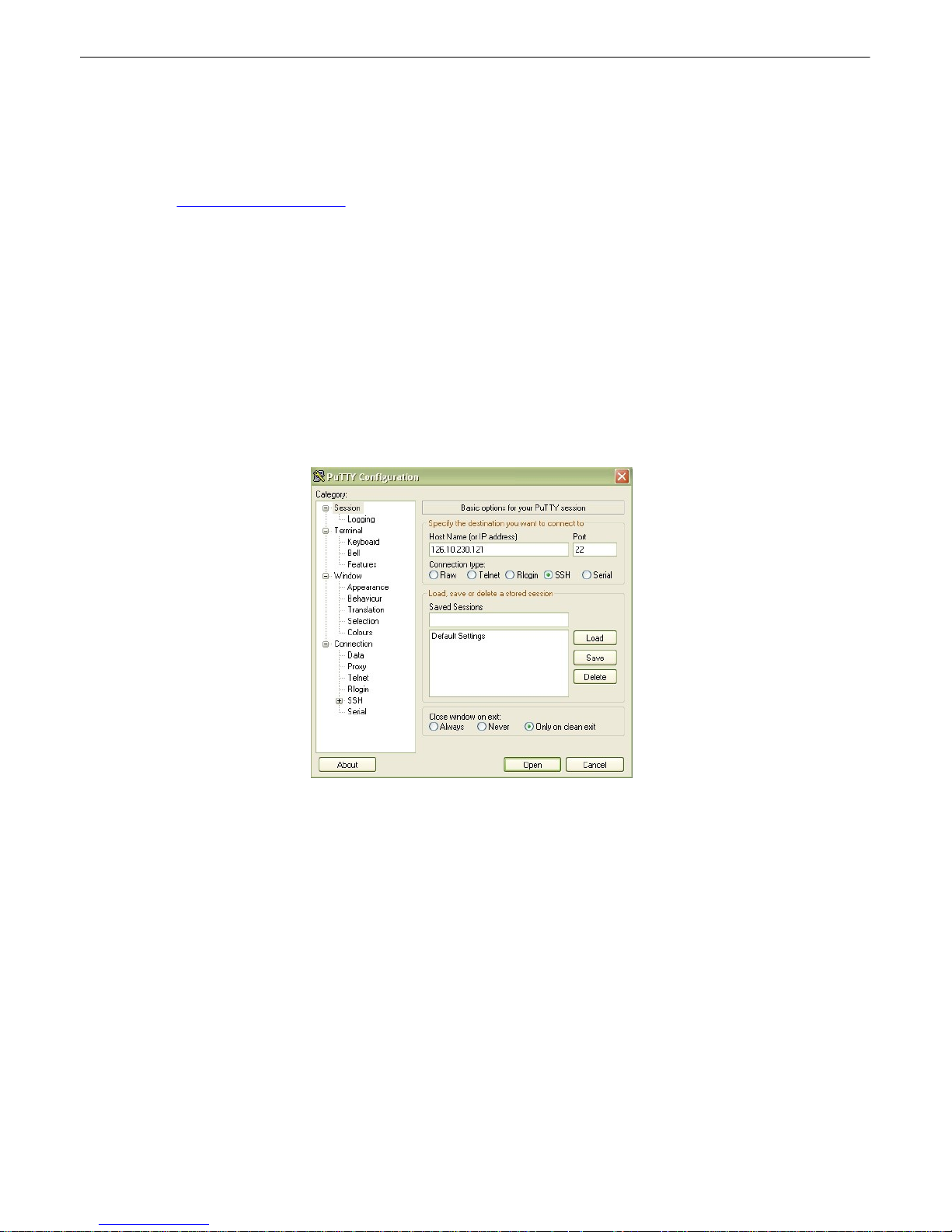
59
Establishing an SSH Session13.1
If your NetGuardian was purchased wi t h the hardwa re acceleration option, you may con nect to your
NetG uardi an's TTY interface v ia SSH session . If yo u are u nsure as to whethe r o r not your NetGu ardia n
is equipped with hardwa re acceleration, reference your NetG uardi an's model n umber (D-PK-NET G5-...)
and contact support@dpstele.com.
DPS Tele com recommends using PuTTY to access the TTY interf ace via SSH session.
To establi sh an SSH sess i o n with your NetGuardian usin g Pu TTY:
· Open Pu t t y
· Click Session
· In the Host Nam e (or IP address) field, in put th e IP of your NetGuardi an.
· To enabl e backspacing w ithin t he TTY int er f ace, cl ick Keyboard on the left pane, underneath
Ter minal . I n th at tab, select Control H u nder Th e Backspace Key option.
· Click Open
· When prom pt ed, enter y our username and passwor d (as w ith a standard TTY session )
U se PuTTY to establish an SSH session with your NetGuardian
Unit Configuration13.2
13.2.1 Ethernet Port Setup
Y ou must assign your NetGuardian's IP a ddress befo re you can connect via LAN/ WA N using a Telnet
client or a Web bro wser. To connect v ia LAN, the mini mum configuration requi res setu p of the IP
add ress and subne t mask. Minimum WAN configuration requires tha t you set the default gatewa y as
well.
Page 65

60
Fig. 1 3.1.1. Configure the Et hernet port parameters
To assign th e NetGuardian's Ethernet Settings
5. Typ e C for th e C)onfi g menu.
6. Type E for E)d it menu.
7. Type E for p ort settin gs, 1 for Net 1, 2 for N et 2.
8. Confi gure t he un it ad dress, subnet mask, a nd de f ault gatewa y.
9. ESC to the main menu.
10.When asked if y ou woul d lik e to save chang e s, type Y (y es).
11.Reboot to save th e new configuration to the NetGuardian.
12. Now you can conne ct to t he NetGua rdian via LAN and use ei t her NGEdit software ov er
LAN or th e Web Browser to complete the con f igura t ion.
13.2.1.1 T1/E1 WAN Setti ngs
E1/T1 WAN Settings
If using the NetGuardi an in an E1 / T 1 WAN netwo rk with DPS Telecom's WAN M UX and VLAN Router
accessories, y ou must also assign t he NetGuardian a WAN ID. Th e WAN ID corresponds to t he ID
number o f th e WAN MUX po rt (1-1 6 ) to whi ch yo u conne ct the N e tGuardia n .
To assign a WA N ID
1. From the E)thernet menu , sele ct the G)lobal option
2. Select the t(1)e1, op tion.
3. Assign a WAN ID, 1-16, corre spo nding to t he WAN MUX port to wh i ch you wi ll connect the
NetGuardian.
Note: If you r NetGu ardia n has a T1/E1 p ort, bu t you are n ot using t he WAN MUX and VLAN Router
accessories, do not assign a WAN ID.
Page 66
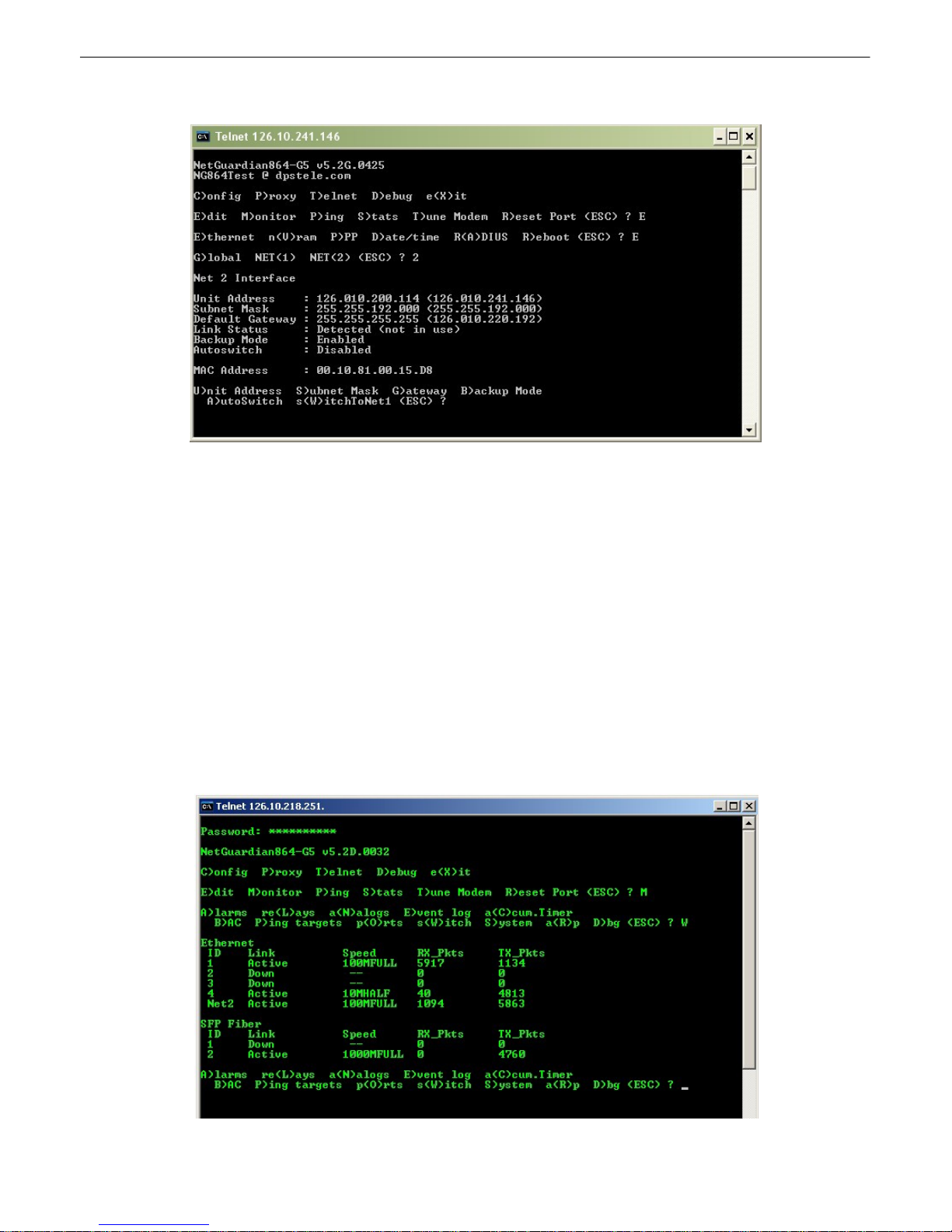
61
13.2.1.2 New! Backup Mode
Enab le "Backup Mod e" to auto matically switch between Net1 and Net 2.
Backup Mod e all ows the NetGuardian t o aut omatically switch betwe en Net1 and Net2 shou ld LAN
connectivity fail. When u sed in Backup Mode, t he NetGuardian has 2 n etwork con nections attached , but
uses only the primary L AN (Net1). When a LAN f ailu re occurs, the un it make s the switch to the
secondary LAN conne ction (Net 2) to main t ain visibility. With th e "Autoswitch" fea t ure en abled, th e
NetG uardi an wil l reve rt back to t he primary LAN conn ection when th e upl ink is re-established.
1. Log in to t he TTY interf ace and go to C)o nfig > E)d it.
2. Go t o E)the rnet > NET(2) to con f igure the Net 2 Interface.
3. Go t o B)ackup Mode to enab le/d isable t his mode, then A)utoswitch to u se the au t omatic netwo rk
switching featu re.
13.2.2 SFP Fiber Connection (For Fiber Build Option)
For NetGuardia n G5 uni t s with GigE Fiber top board , you also can view and edit switch an d SFP fiber
connections in the TTY interf ace. A f t er loggin g in, sel ect M)onitor > sW)itch to view deta ils for the
10/100/ 1000 BaseT switch and F iber i nterface.
Fig. 1 3.1.2 SFP fib er conne ction de t ail in the TTY interfa ce
Page 67

13.2.3 Edit PPP Port
Choose P)PP to edit yo ur baud rate, de pending on wha t device has been chose for t he PPP port.
62
Fig. 1 3.1.3 Edit you r PPP port
If you are using a mod em for the PPP port, t hen cho ose mo(D)emto defi ne th e modem ini t ialization
strings.
Choose B)au d to de fi ne the bau d rat e for th at port.
Fig. 1 3.1.4. Select the b aud ra t e for your PPP port
Page 68

63
13.2.4 Tune 202 Modem
Tuning t he 20 2 modem on a NetG uardi an G5 can only be do ne fro m the TTY interfa ce (u sin g either
Hy p e rTe rmina l thro u g h th e fron t craft po rt or by te l ne t ov e r LAN on po rt 20 0 2).
Fig. 1 3.1.4. Press 'T' to tune the 202 Mod em with the T T Y interf ace
Though no menu opti ons will a ppear, use the fol lowing commands to tune the 202 modem. Each menu
option, wh en chosen, wi ll output t he chara cter "A " on screen:
1) Mi nor Ad just DB+
2) Mi nor Ad just DB-
3) H igh Freq uency
4) Low Frequen cy
5) Off
6) Ma jor Ad just DB-
7) Ma jor Ad just DB+
8) M e di a n Freq ue ncy (A v e rag e of hi gh and low freq ue ncy)
A f t er selectin g an o ptio n (like #1 in this example) fo r Minor Adju st th e DB+ level, the NetGuardian will
return a '+' command to i nform you the t ask is completed . E ach time yo u hit a number key (1-8), t he
NetG uardi an wil l a '+' on your screen.
Page 69

13.2.5 RADIUS Configuration
Global Settings
Retry
How many times the RA DIUS serv er will retry a logon
attempt
Time-out
Enter in th e number of seconds bef ore a logo n request is
timed o ut
Servers 1 / 2
IPA
Enter t he IP address of the RA DIUS server
Port
Port 1812 is an industry-stan dard p ort for using RADIUS
Interface
Use the drop-do wn men u to choose betwe en NET1 a nd
NET2
Secret
Enter t he RADIUS secret in th is field
The T T Y inte rf ace can also be used to config ure RADIUS settings. Af t er entering the IPA f or the RADIUS
server, users will be pro mpted for both a username and password to l ogon to th e unit. This username
and password combination will be verifie d aga inst the RADIUS database, and not the lo cal data base.
The local p assword d atabase will only be used for front p anel craft port a ccess in the e vent the RADIUS
config urati on is making th e uni t othe rwi se i naccessible.
64
Fig. 1 3.1.5. The RADIUS c onfiguration menu using the TTY interface.
Fig. 1 3.1.5.2 RADIUS logon screen prompts f or a Username and Password.
Page 70

65
Fig. 1 3.1.6 To enter Command Line mode, login to
the TTY, t hen press Ctrl+C.
Tips for using TTY Command Mode
· To enter command mode , logi n to the TTY
interface and pre ss Ctrl + C.
· To vie w all accept abl e ope rati ons, type get help,
then press Enter.
· Inv alid commands will return " E rro r" as the
response.
· A CRLF is sent by the RTU following all
responses from the RTU.
· Limite d dat a validation is in p lace using t his method . Use caution when setti ng variable values.
· In some cases, you n eed to reboot the NetGuardian f or ne w v ariable values to take effect.
· Changing REF1, REF2, DISP1, or DISP2 affects the MAJOR, MINOR, OVER, and UNDER alarm
thresho lds. Chan ging any of the se sett i ngs should be che cked an d re-established as requ ired.
· In th e table below, variable s (pa rams) are note d in b rackets.
Operation
Command
Params
Help
get help
None
Initia l i ze NVRAM
ini t nvra m {g2 }
None
Write NVRAM
set nvram
None
Read NVRAM
get nvra m
None
V i ew System Up Time
get sysup t ime
None
V i ew F i rmwa re V ersion
get prodid
None
Data Port Description
{get, set} data port {1 . . . 9} desc
string {0 . . . 15} chars
Data Port Baud
{get, set} data port {1 . . . 9} bau d
{1200,300,600,1200,2400,48
00,
9600,19200,38400,57600,115
200}
Data Port Format
{get, set} data port {1 . . . 9} wfmt
{8n1,8n2,7n1,7e1,7o1,8
o2,8o1}
Data Port RTS Head
(msec)
{get, set} data port {1 . . . 9} rtshead
{0..255}
Data Port RTS Tail
(msec)
{get, set} data port {1 . . . 9} rtstail
{0..255}
Data Port Ty p e
{get, set} data port {1 . . . 9} typ e
{off,tcp,ptcp,htcp,rtcp,udp,ch
an, crft,cap , ecu,sps8}
13.2.6 UnitKal
UnitKa l settings are confi gurab le fro m the TTY interfa ce o nly. When used al ong wit h the UnitKal system,
the NetGuardi an has the ab ilit y to remotely calib rate sensors at user d efin able t ime intervals. This
system removes the cha nces of human error whe n calibratin g sensors. It helps to redu ce the waste o f
Calibrati on ga s, and wil l offe r better results when a sensor is in n eed o f replacement. For more
information, vi ew the T KP t hat is di stribute d with Se nsor (D-PK-SENSR-12106 . 00001).
13.2.7 New! - TTY Command Mode
This command line mode offers an alte rnate wa y of configuring t he NetGua rdian G5 . T his interface is
script able, and is recommend ed for adv anced users. Entries are NOT case sensitiv e.
Page 71

66
# of NetGuardian
Expanders
{get, set} ngddx
{0...3}
# of GLD or BSU
{get, set} gld
{0...16}
Timed Tick Period
{get, set} t imed tick
{0...60} {min}
System Name
{get, set} name
string {0 . . 31} chars
System Location
{get, set} location
string {0 . . 31} chars
System Contact
{get, set} contact
string {0 . . 31} chars
System Phone
{get, set} phone
string {0 . . 20} chars
Reboot
set rebo ot
None
DCP Unit ID
{get, set} dcpadd r
{0...255}
DCP Port Num b er
{get, set} dcpport
{1..32767}
DCP Port Type
{get, set} dcptyp e
{udp,tcp,serial}
DCP Protocol
{get, set} dcpprot
{dcpx,dcpf,dcpe}
DCP Autonomous Time
{get, set} dcpautotm
{0..1 20} {sec,min}
Network Time IPA
{get, set} ntpi pa
IP Addre ss
Username
{get, set} username {1. . . 16}
string {0 . . . 18} chars
Password
set password {master, 1.. . 16}
string {0 . . 15} chars
Access Rights
{get, set} access {1...16}
{000 0..01ff} where
Bit.0 – 1=admin
Bit.1 – 1=dat abase
Bit.2 – 1=monitor
Bit.3 – 1=rly con t rol
Bit.4 – 1=reachthru
Bit.5 – 1=modem
Bit.6 – 1=tel net
Bit.7 – 1=sd_monit or
Bit.8 – 1=ppp
Network IPA
{get, set} net {1 , 2} ipa
IP Addre ss
Subnet Mask
{get, set} net {1 , 2} subne t
Subnet
Gateway IPA
{get, set} net {1 , 2} gat eway
Gateway
Proxy Base
{get, set} prox ybase
{1..32767}
Analog Descripti o n
{get, set} alg {1...8 } desc
string {0 . . 48} chars
Analog Display Unit
{get, set} alg {1...8 } unit
string {0 . . 3} chars
Analog Majo r Under
Threshold
{get, set} alg {1...8 } t hres mju
{-94.0000...94.0000}
Analog Minor Under
Threshold
{get, set} alg {1...8 } t hres mnu
{-94.0000...94.0000}
Analog Minor Over
Threshold
{get, set} alg {1...8 } t hres mno
{-94.0000...94.0000}
Analog Majo r Over
Threshold
{get, set} alg {1...8 } t hres mjo
{-94.0000...94.0000}
Analog Trap
{get, set} alg {1...8 } t rap
0=trap disabled
1=trap enab led
Analog Primary
Notification
{get, set} alg {1...8 } pri
{0...8}
Analog Second ary
Location
{get, set} alg {1...8 } sec
{0...8}
Page 72

67
Analog Po l arity
{get, set} alg {1...8 } pola rity
0=Normal
1=Reversed
Analog Group Number
{get, set} alg {1...8 } group {mju , mnu , mno , mjo }
{1...8}
Analog Reference 1
VDC
{get, set} alg {1...8 } ref1
Number
Analog Reference 1
Display
{get, set} alg {1...8 } disp1
Number
Analog Reference 2
VDC
{get, set} alg {1...8 } ref2
Number
Analog Reference 2
Display
{get, set} alg {1...8 } disp2
Number
Analog Deadba n d
{get, set} alg {1...8 } dead band
{0.1...9.9}
Alarm Description
{get, set} alm {base,e xp1,ex p2,exp3} {1...64}
desc
string {0 . . . 48} chars
Alarm Polarity
{get, set} alm {base,e xp1,ex p2,exp3} {1...64}
polarity
0=Normal
1=Reversed
Alarm Trap
{get, set} alm {base,e xp1,ex p2,exp3} {1...64}
trap
0=trap disabled
1=trap enab led
Alarm Prima ry
Notification
{get, set} alm {base,e xp1,ex p2,exp3} {1...64} pri
{0...8}
Alarm Seconda ry
Notification
{get, set} alm {base,e xp1,ex p2,exp3} {1...64}
sec
{0...8}
Alarm Group
{get, set} alm {base,e xp1,ex p2,exp3} {1...64}
group
{1...8}
Global Trap IP Address
{get, set} t rap {1, 2} ipa
IP Addre ss
Global Trap Format
{get, set} t rap {1, 2} format
{v1, v2c, v2cinf,v3}
LCD Display Mode
{get, set} lcdmode
{scroll,point}
LCD Delay Time (for
Point Mode)
{get, set} lcddel ay
{1..6 0} {sec}
· Y ou wan t t o find out how long th is NetGuardian
has been runnin g (since last rebooted.) Get
system uptime by typin g get sysuptime, the n
press Enter.
· Y ou wan t t o see the alarm de scripti on for Base
A la rm 1. To see the descriptio n, type get alm
base 1 desc
· Y ou wan t t o set the Global Trap IP A ddress to
126 .10 .230 .13 3. To enter this, type set trap 1
ipa = 126.10.23 0.133
· Y ou wan t t o change the LCD mode from Scroll
(defa ul t) to Poin t Mode. To chang e thi s, type set
lcdmode = point
Examples
Page 73

13.2.8 DSCP Configuration
68
Confi gu re your Seri al /Dat a Ports throu g h the Edit > Ports screen
Page 74

69
Note: If your unit has an i nternal wire l ess radio, you will use p ort 1 fo r DSCP communication.
Use the fo llowing steps to con f igure your DSCP device setting s:
1. Lo cate the RS2 32 data port to be used (ie: d ata port 3) l ocated o n the back of t he NetGua rdian.
2. Connect a RS23 2 serial cab le be t we en th e RS232 data port and th e serial port o f Wirel ess Receiv er.
For pin ou t, refe r to section 6.7 Data Ports.
3. Lo g int o the NetGuardi an's Web interf ace.
4. Click Edit > Ports. Th is open s the Ports screen.
5. Click on th e typ e (def ault: "OFF") located i n the T ype column for the data port ID (ie: data port 3) row.
This open s the Data Ports screen .
6. Sel ect DSCP using the dropdown located in the Type column for th e data port ID row.
7. Click th e Sub mit Data b ut to n. The fi el d s: Descript i on , Ba ud , e tc, will b e au to mati call y po p u la te d .
8. Verify Descripti on is set to " DSCP port".
9. V eri fy Baud is set to 9600.
10.Cl ick on Edit > DSCP (Wireless Sensor)
11.Select th e typ e of DSCP de vice. For example, if yo u have purchased the wireless propane monit or,
you woul d select "Propane Monito r".
12.Cl ear th e Module A ddress Hi gh an d Low field s. After submitting, th ey should b oth re ad al l zeros.
13.Cl ick 'Submit Dat a' to save your settin gs.
14.Re boot t he NetGuardian G5.
15.Once the NetGua rdian comes back online, give it a f ew moments to ini t ialize the wireless radio. You
will t hen press and ho ld th e sync button on the wireless transmitter u ntil you see the LED become li t .
Once this is don e, the NetG uardi an and Wireless Transmitter will become synchronized . If yo u
refresh the DSCP page, y ou shou ld no w see an ad dress valu e in the "Module Address" fields.
16.Now configure the Anal og Cha nnel s: Fo r Propane Mon, channel 1 is Propa ne QTY in units Percent ,
with ra nge 0 - 100 . Ch annel 2 i s ba t t ery p ower. Sin ce b attery is 3.6 V, Minor over an d Major over
should be 3.7 and 3. 8. Minor Under = 3.2 , Major Under = 3 . 0
Page 75

Confi gure you r external DSCP devices through the Edit > DSCP screen
Module Configuration
Module Address
High
4-byte i dentificati on ad dress that is au t omatically acquired wh en the DSCP
device is synced wit h the NetGuardi an.
Module Address
Low
4-byte i dentificati on ad dress that is au t omatically acquired wh en the DSCP
device is synced wit h the NetGuardi an.
Update Frequency
How ofte n the wi reless transmitter will wak e from low-p ower mode a nd send a
measurement re ading to t he NetGua rdian.
Type
The spe cific type of DSCP dev ice (Propa ne Monit or, Track Moni t or, et c...).
Level Detection (Prop ane Sensor Ty p e Only)*
Read Frequency
This value determines how o f t en the wirel ess tran smitter wi ll wak e up and take
a measurement . If the value has dropp ed more th an th e Level T hreshold, the
uni t wi ll exit low-powe r mod e and send a reading to the NetGu ardian.
Otherwise, i t wi ll send a read ing only when t he Update Fre quency time ha s
passed. Th is allo ws yo u to acqu ire readin gs more often when t he tank i s be ing
actively emptied , at the expense o f t he hi gher batte ry usage. Input '0' to disable
this feature . T his val ue must be smalle r t han the "Update F requency" value.
Level Threshol d
This is the percentage that the pro pane reading must dro p bet we en rea dings
to exit low-po we r mod e and sen d the readi ng to t he NetGuardian. (See above)
Generator Running Detection (Propane Sensor Type Only)*
Gen. Runni n g
Frequency
When the spe cified alarm point (from Generato r Point Re f erence) i s set, th e
timer value for Generator Ru nning Frequency will ove rri de th e timer value for
Updat e Frequency (unde r Mod ule Config uration). This takes effect aft er the
next up date.
Generator Point
Reference
Specify the Di spl ay and Point at t ached to Ge n. Running F requency. Input '0 ' to
disable th is feature.
70
Advanced Configuration and Details:
Page 76

71
*Note: Generator Run and Level Detection featu res are desig ned t o det ect changes faster wh ile
maximizing battery life. T hey are entirely optional t o use.
Page 77

Monitoring13.3
13.3.1 Monitoring the NetGuardian
Connect a PC runn ing VT100 t erminal emulation softwa re to the craft port or connect via LAN using a
Telnet client with VT100 emula t ion to port 2002 t o reach the monit or menu selection. T his section allows
you to d o full system monitori ng of t he NetGua rdian including: all alarms, pi ng in f ormation, relays,
ana logs, and system status.
Fig. 1 3.3.1.1. The moni t or menu allows status checking on all element s
13.3.1.1 Monitoring Base Alarms
72
V iew the status of th e device conn ected to t he di screte a larms from the M)onitor menu > A)larms
option. Under Status, the word Alarm will appe ar if an ala rm has been activ at ed and Clear will ap pear i f
an a larm condit ion i s no t present. If grou ps are used t he user defined status will be displa yed.
Fig. 1 3.3.1.1.1 . T his example shows pag e two of t he discrete alarms
Page 78

73
13.3.1.2 Monitoring Ping Targets
V iew the status of all y our pi ng ta rgets from the M)on itor menu > P)i ng targets opt ion. T his screen
displa y s the pin g ta rge t I D, de scriptio n, and I P ad dre ss. Unde r Status the word Alarm wi ll appea r if an
ala rm has been activa ted and Clear will appe ar if a n ala rm conditio n is not p resent.
Fig. 1 3.3.1.2.1 . T he Ping in f o submenu allo ws you to cha nge p ing t argets
13.3.1.3 Monitoring and Operating Relays (Controls)
The NetGuardi an comes equi pped wi t h 8 relays that can be used to control exte rnal devices. Moni t or the
status of y our relays from the M)onito r men u > R)elays option.
Relays are set to normall y open (N/O) as the f actory d efault, but each o r all of the m can be chang ed to
normally closed (N/C) by changing their respective ju mpe r (see t he section t itled "Con t rols").
Fig. 1 3.3.1.3.1 T he eight relays can be o perat ed from this screen
Page 79

13.3.1.4 Monitoring Anal ogs
V iew the current re ading an d the alarm status of your anal og devices from the M)on itor menu > a (N)logs
option. T he value shown is a snap sho t of the chann els measurement, n ot a re al-time re ading. Refresh
the readings by re-selectin g the analogs opt ion. Alarm status indicates that a preset t hreshold has be en
crossed and is design ate d by an x.
The eight analog measuring inputs are set to measure vo ltag e as the factory d efault. If your sen sors
output i s current , cha nge the appropriate analog dip switch, to the curre nt measurin g positi on. The
scaling worksheet in th e provision ing section converts all re adings shown he re into native units, such as
deg rees Celsius or percent rel ative hu mid ity.
74
Fig. 1 3.3.1.4.1 . T his display allows you to mon itor your e ight anal og inputs
13.3.1.5 Monitoring System Al arm s
V i ew th e statu s of the N e tGuardia n 's system ala rms from the M )o n i to r menu > S)ystem optio n . Under
Status, the word Alarm will appe a r if an ala rm has been activ at ed and Clear will ap pear i f an alarm
condit ion is not pre sen t . See Append ix, "System A larm Descript ions," f or more inf ormation. If groups are
used th e user de f ined stat us will be displaye d.
Page 80

75
Fig. 1 3.3.1.5.1 . System Alarms can be viewed f rom the M)onit or menu > S)ystem optio n
13.3.1.6 Monitoring Data Port Acti vi t y
V iew the status of th e N etGuardian's 8 data ports from the M)oni t or menu > p(O)rts option. Enter th e
number of the port you wish to vi ew and pre ss Ente r.
The N etG u ard ia n prov id es an ASCII de scription unde r Transmit and Receive. Choose a ) T ransmit to
view data transmitted to a nother device. Choose b) Receive to vi ew data received from an othe r device.
See A p pe nd ix , "ASCII Conv e rsion ," fo r specific ASCI I symbol conve rsion .
Fig. 1 3.3.1.6.1 . Da t a port activity can be viewed f rom the M)onit or menu > p(O)rts opt i on
13.3.1.7 Monitoring the Accumulat i on Timer
The Accumulation T imer kee ps a runn ing total of the amount of time a point is in a n alarm state. An
ala rm poin t th a t exceeds a user def in e d thre shol d will tri gg e r a Accumulatio n Eve n t system alarm.
Refer to Fig ure 13 . 3.1.7.1. a nd Ta ble 1 3.3.1.7.A to def ine the accumulation t imer.
a
Page 81

Fig. 1 3.3.1.7.1 . Mon itor a nd reset the Accumulator T imer
Field
Description
Disp l ay and P oi n t
Reference
Indicates which alarm point is to be monitored.
Point Description
The user-defined description of the monitored alarm point.
Point Sta tus
The current st at us of the monitored point.
Eve nt Thre shold
Amount of time allowed to accumulate before the sys t em alarm,
“Accumulation Even t” is triggere d. Note: M ax imum is 45 days.
Accumulated Tim e
The total time t he monitored point has been in an ALARM st ate.
Accumulated Si nce
Indicates t he last t im e the acc umulation tim er was reset.
Reset Accumulation
Timer
Selecti ng this option will reset the timer.
76
13.3.1.8 Monitoring DSCP Devices
View the status of the DSCP Analog s from the Monito r > DSCP screen
This Monit or > DSCP screen provi des a descripti on of each DSCP dev ice ala rm po int state and each
DSCP device ana log channel, the curre nt rea ding , t he units bei ng read, a larm condit i ons (major under,
minor under, maj or over, an d minor over), and t he la st instance of data t ransfer (Last Update ) according
to y our analo g settin gs.
Page 82

77
13.3.2 Viewing Live Target Pings
Choose P)i ng to ping any of the NetGuardi an's user defined IP addresses. Then enter the ID number (1-
32) o f t he IP address or ent er any IP ad dress to pin g.
Fig. 1 3.3.2.1. Contin uously pin g an I P addre ss that has been def ined in th e NetGuard ian's ping ta ble
Page 83

13.3.3 Proxy Menu
Y ou can creat e proxy connection s to reach-through to th e craft po rt , mod em port or a ny o f t he other
eig ht serial ports from the P)rox y menu. You'll be able to monitor and con t rol additional de vices via proxy
connection to t he NetGuardian. Data presente d and handshak ing wi l l be spe cified by th e conne cted
device.
To cancel t he proxy con nection wait a half second, then qu ickly t ype @@@ a nd pre ss ENTER.
To send a Ctrl-Break to a terminal serve r, t ype \brk and p ress EN T ER.
78
Fig. 1 3.3.3.1. Access devices connected to the ei ght d ata ports on th e back panel through M)onito r
menu > P)roxy option
13.3.4 Event Logging
Choose E)vent log to vi ew the u p to 1 00 event s po sted to the NetGuardian; inclu ding powe r u p, base
and system al arms, pi ng alarms, analog alarms, and cont rols. Posted e vents for the various ala rms
include both alarm and cle ar status. Refer t o Tab le 13 . 3.4.A for ev ent l og field descriptions.
Note: All info rmation in the ev ent log wil l be e rased up on reb oot or a po we r f ailu re.
Fig. 1 3.3.4.1. Monitor the la st 100 even t s recorded by the NetGuard ian f rom the M)onit or menu > E)
Page 84

79
Eve nt Log Fi eld
Description
Evt
Event number (1–100)
Date
Date the event occurred
Time
Time the event occ urred
Grp
Alarm Group
State
State of the event (A=alarm, C=cl ear)
PRef
Point reference (See Appendix A for display descriptions).
Description
User defined description of the event as entered in the alarm point and
relay description fields.
vent lo g opt ion
Table 13. 3.4.A. Event Log f ield descriptio ns
13.3.5 Backing Up N etGuardian Configuration Data via FTP
1. From the St art menu on your PC, sele ct RUN.
2. Typ e "ftp" followe d by t he IP address of the N etGuardian you are ba cking up (e.g. ftp
126.10.120.199).
3. A f t er the con nection is made press Enter.
4. Enter t he password o f t he NetGuardian (def ault password is dpstelecom), then press Enter.
5. Typ e "binary" and pre ss Enter (n ecessary f or N etGuardian file t ransfer).
6. Typ e "lcd" and p ress Ente r (t his all ows you to cha nge t he di rectory o f your local machin e).
7. Typ e "get" fo llowe d by t he name you wi sh to def ine for the NetGu ardian ba ckup fi le. Add the
ext ension ".bin" to t he file name (e.g. get n gdbkup. bin) a nd press Ente r.
8. A f t er reloadi ng, type "by e" an d press Enter t o exit.
Note: The backup file name can have a maximum of eight characters before t he file e xtension.
13.3.5.1 Reloading NetGuardian Configuration Data
1. From the St art menu on your PC, sele ct RUN.
2. Typ e "ftp" followe d by t he IP address of the N etGuardian you are ba cking up (e.g. ftp
126.10.120.199).
3. A f t er the con nection is made press Enter.
4. Enter t he password o f t he NetGuardian (def ault password is dpstelecom), then press ENTER.
5. Typ e "binary" and pre ss Enter (n ecessary f or N etGuardian file t ransfer).
6. Typ e "lcd" and p ress Ente r (t his all ows you to cha nge t he di rectory o f your local machin e).
7. Typ e "put" fo llowe d by t he name you defi ned for the NetGu ardian ba ckup fi le an d press Enter
(e.g. put n gdbkup. bin).
8. Typ e "literal REBT" to reboot the NetGuardian.
9. A f t er reloadi ng, type "by e" an d press Enter t o exit.
Page 85

13.3.6 Debug Input and Filt er Options
Debug I nput Options
ESC
Ex it Debug
B
Show BA C status points
T
Show task status
U
Show DUART information
R
Show network routing table
X
Clear debug enable bitmap. Turn all debug filters OFF
?
Display Options
Debu g Filter Optio n s:
a
(1) Alarm toggle switch. Shows posting of alarm data
A
(2) Analog toggle switch. Shows TTY interface debug
c
(3) Config toggle switch. Shows TTY interface debug
C
(4) Control relay toggle switch. Shows relay operation
d
(5) DCP responder toggle switch. Shows DCP protocol
D
(6) Dev ice toggle switch. Shows telnet and proxy information and NGEditG5 serial
communication.
e
(7) Expansion poller toggle switch. Shows NGDdx polling
E
(8) ECU Interrogator toggle switch. Shows BA C processing
f
(9) FTP Command toggle switch. Shows command string parsing
F
(10) FTP Data toggle switch. Shows FTP Read / Write
G
(11) GLD poller toggle switch. Shows GLD polling
h
(12) HTML debug switch. Shows Web Browser processing
H
(13) HWACS debug switch. Shows hardware access operation
i
(14) PING toggle switch
k
(15) Socket toggle switch. Shows current dcu resources
l
(16) LED toggle switch. Shows current LED state
L
(17) LCD display t oggle switch. Shows LCD control and text
m
(18) Modem toggle switch. Shows modem vectored initialization
M
(19) Undefined
o
(20) Osstart toggle switch. Miscellaneous application debug, including NV RAM read
and write operation, and event posting
O
(21) Undefined
p
(22) SPORT toggle switch. Port init debug and channeled port debug
P
(23) PPP toggle switch. Shows PPP functioning
q
(24) QAccess toggle switch. Reserved for future use
Q
(25) Undefined
r
(26) Report toggle switch. Shows reporting event activity, including SNMP, pagers,
email, etc. Also shows PPP negotiation for NG client PPP mode.
s
(27) SNM P t oggle switch. Reserved for future use
S
(28) STAK t oggle switch. Shows network processing and IPA of arp requests. Also
shows packets discarded by F ilter IPA.
t
(29) TERM toggle switch. Shows UDP/TCP port handling. The camera and network
time (NTP) jobs also use the TERM toggle switch
V
(30) Undefined
w
(31) HTTP t oggle switch. Shows handling of web browser packets
W
(32) WEB toggle switch 2. Dump HTM L t ext from web browser
80
Page 86

81
Port
Address
Display
Description
Set
Clear
9911
Discrete Alarms 1-32
For NetGuardian 864 Alarms 1-64
8001-8032
8001-8064
9001-9032
9001-9064
9912
Ping Table
8065-8096
9065-9096
9913
Analog Channel 1**
8129-8132
9129-9132
9914
Analog Channel 2**
8193-8196
9193-9196
9915
Analog Channel 3**
8257-8260
9257-9260
9916
Analog Channel 4**
8321-8324
9321-9324
9917
Analog Channel 5**
8385-8388
9385-9388
9918
Analog Channel 6**
8449-8452
9449-9452
9919
Analog Channel 7**
8513-8516
9513-9516
99110
Analog Channel 8**
8577-8580
9577-9580
99111
Relays/S y s t em A larms (See table below)
8641-8674
9641-9674
Port
Address
Display
Description
Set
Clear
99112
NetGuardian 480 (as DX) Alarms 1-64
6001-6064
7001-7064
99113
NetGuardian 480 (as DX) Relays 1-4
6065-6069
7065-7069
99113
NetGuardian 480 (as DX) Alarms 65-80
6081-6096
7081-7096
Reference Section14
Display Mapping14.1
Table 14. 1.A. Display de scripti ons and SNMP Trap numbers for the NetGua rdian
* The TRAP number ranges shown correspond to t he point range of each display. For ex ample, the
SNMP Trap "Set" numbe r for alarm 1 (in Display 1 ) is 8001, "Set" f or ala rm 2 i s 80 02, " Set" fo r alarm 3
is 8003, etc.
** The TRAP number de scripti ons for the Anal og chan nels (1-8) are in the f ollowing order: min or und er,
minor over, major un der, and majo r over. F or ex ample, for Anal og chan nel 1 , t he "Set" number for min or
und er is 812 9, minor o ver is 8130, maj or und er is 813 1, and major o ver is 8132.
Expan sion Unit Display Maps
Display descripti ons and SNMP Trap numbers for th e NetGuardian 480 as an Expansio n
Page 87

Port
Address
Display
Description
Set
Clear
99112
NetGuardian DX48 Ex pansion 1 Alarms 1-48
6001-6048
7001-7048
99113
NetGuardian DX48 Ex pansion 1 Relays 1-8
6065-6072
7065-7072
99114
NetGuardian DX48 Ex pansion 2 Alarms 1-48
6129-6177
7129-7177
99115
NetGuardian DX48 Ex pansion 2 Relays 1-8
6193-6200
7193-7200
99116
NetGuardian DX48 Ex pansion 3 Alarms 1-48
6257-6305
7257-7305
99117
NetGuardian DX48 Ex pansion 3 Relays 1-8
6321-6328
7321-7328
Display descripti ons and SNMP Trap numbers for th e NetGuardian DX48 Expan sio n
Port
Address
Display
Description
Set
Clear
99112
NetGuardian 832A Ex pansion 1 (as DX) Alarms 1-32
6001-6032
7001-7032
99113
NetGuardian 832A Ex pansion 1 (as DX) Relays 1-8
6065-6072
7065-7072
99114
NetGuardian 832A Ex pansion 2 (as DX) Alarms 1-32
6129-6161
7129-7161
99115
NetGuardian 832A Ex pansion 2 (as DX) Relays 1-8
6193-6200
7193-7200
99116
NetGuardian 832A Ex pansion 3 (as DX) Alarms 1-32
6257-6289
7257-7289
99117
NetGuardian 832A Ex pansion 3 (as DX) Relays 1-8
6321-6328
7321-7328
Port
Addres
s
Display
Description
Set
Clear
99112
NetGuardian 864A Ex pansion 1 (as DX) Alarms 1-64
6001-6064
7001-7064
99113
NetGuardian 864A Ex pansion 1 (as DX) Relays 1-8
6065-6072
7065-7072
99114
NetGuardian 864A Ex pansion 2 (as DX) Alarms 1-64
6129-6192
7129-7192
99115
NetGuardian 864A Ex pansion 2 (as DX) Relays 1-8
6193-2000
7193-7200
99116
NetGuardian 864A Ex pansion 3 (as DX) Alarms 1-64
6257-6320
7257-7320
99117
NetGuardian 864A Ex pansion 3 (as DX) Relays 1-8
6321-6328
7321-7328
Port
Addres
s
Displa
y
Description
Set
Clear
99118
NetGuardian G5 (832A/864A) Expansion 1 (as DX)
Analog Channels
Channel 1
6385-6388
7385-
7388
Channel 2
6389-6392
7389-
7392
99119
NetGuardian G5 (832A/864A) Expansion 1 (as DX)
Analog Channels
Channel 3
6393-6396
7393-
7396
Channel 4
6397-6400
7397-
7400
99120
NetGuardian G5 (832A/864A) Expansion 1 (as DX)
Analog Channels
Channel 5
6401-6404
7401-
7404
Channel 6
6405-6408
7405-
7408
99121
NetGuardian G5 (832A/864A) Expansion 1 (as DX)
Analog Channels
Channel 7
6409-6412
7409-
7412
Channel 8
6413-6416
7413-
7416
99122
NetGuardian G5 (832A/864A) Expansion 2 (as DX)
Analog Channels
Channel 1
6417-6420
7417-
7420
Channel 2
6421-6424
7421-
7424
99123
NetGuardian G5 (832A/864A) Expansion 2 (as DX)
Channel 3
6425-6428
7425-
Display descripti ons and SNMP Trap numbers for th e NetGuardian DX G5 (832A mod el)
82
Display descripti ons and SNMP Trap numbers for th e NetGuardian DX G5 (864A mod el)
Page 88

83
Port
Addres
s
Displa
y
Description
Set
Clear
Analog Channels
7428
Channel 4
6429-6432
7429-
7432
99124
NetGuardian G5 (832A/864A) Expansion 2 (as DX)
Analog Channels
Channel 5
6433-6436
7433-
7436
Channel 6
6437-6440
7437-
7440
99125
NetGuardian G5 (832A/864A) Expansion 2 (as DX)
Analog Channels
Channel 7
6441-6444
7441-
7444
Channel 8
6445-6448
7445-
7448
99126
NetGuardian G5 (832A/864A) Expansion 3 (as DX)
Analog Channels
Channel 1
6449-6452
7449-
7452
Channel 2
6453-6456
7453-
7456
99127
NetGuardian G5 (832A/864A) Expansion 3 (as DX)
Analog Channels
Channel 3
6457-6460
7457-
7460
Channel 4
6461-6464
7461-
7464
99128
NetGuardian G5 (832A/864A) Expansion 3 (as DX)
Analog Channels
Channel 5
6465-6468
7465-
7468
Channel 6
6469-6472
7469-
7472
99129
NetGuardian G5 (832A/864A) Expansion 3 (as DX)
Analog Channels
Channel 7
6473-6476
7473-
7476
Channel 8
6477-6480
7477-
7480
Display descripti ons and SNMP Trap numbers for th e NetGuardian DX G5 (832A/ 864A) Analo g
Channels
Note: If D-Wire to p is present , sen sors 1 - 16 repl ace Expansion 2 and Expansion 3 analog cha nnels.
Page 89

14.1.1 System Alarms Display Map
Display
Points
Alarm P oi nt
Description
Solution
11
1-16
Control Relays
Reserved by sys t em for control relays .
Reserved by sys t em for control relays .
17
Timed Tick
Toggles stat e at c onst ant rate as
configured by the Tim ed Tick tim er
variable. Useful in test i ng integrity of
SNMP trap alarm reporting.
To turn the feature off, set the Timed
Tick t i mer to 0.
18
Exp. Module
Callout
Alarm is t riggered whenever an alarm
point from an Entry Control Unit (ECU)
is c ollec t ed. A noti fication event may
be associated with the alarm to force a
call out or trap.
Disable Building Acces s Control (BAC)
by set t ing the BAC Unit ID to 0. If
Building Acc es s is being used, then
invest igate t he ECU alarm source or
don’t associ ate notification with the
alarm event.
19
Network Time
Server
Communication with Network Time
Server has failed.
Try pinging the Network Time Server’s
IP Address as it is configured. If the
ping test is s uc c es s ful, then check t he
port setting and verify the port is not
being block ed on your network.
20
Accumulation
Event
An alarm has been standing for the
time configur e d under Accum. Timer .
The Acc umulation tim er enables y ou to
monitor how long an alarm has been
standing despite sy s t em reboots. Only
the user may reset the acc umulated
time, a reboot will not.
To turn off the feature, under
Accum.Timer, set the display and point
reference to 0.
21
Duplicate IP
Address
The unit has detected another node
with the same IP Address .
Unplug the LAN cable and contact y our
network administ rator. Your network
and the unit will most l ik ely behave
incorrectly. A fter assigning a correct
IP Address , reboot the unit to clear the
System alarm.
22
WAN
Disconnected
WA N Top Board is present but t he
WA N connection is not detect ed.
Check the back of the unit and confirm
WA N cable is connected and WA N
LED is solid green.
23
ECU
Emergency
Unlock
Set when both user-defined fire and gas
alarms occur.
Wil l c l ear when fire and gas alarms
clear. Feature can also be disabled if
"Emergency Unlock Enabled" is
unchecked from the web or NGEdit G5
interfaces.
24
D-Wire Sensor
Not Detected
A configured D-Wi re Sensor is not
detected.
Check G5 D-W ire port and D-Wire
Sensor and confirm c able is plugged in.
Als o make s ure that configured ROM
ID's matc h the D-Wire Sensors plugged
in.
25
ECU Door
Violation
Door sensor has detected unauthorized
entry.
Verify integrity of door sensor. This
alarm is to alert of unauthorized
access.
26
Maintenance
Mode
Maintenance mode is c urrently act i ve
for the server shutdown feature
Maintenance mode will timeout
according t othe amount s pecified by
the user in teh NGEdit " S erver
Shutdown" tab.
27
DSCP Timeout
The unit has not received a signal from
Check configuration of DSCP Poller.
84
Page 90

85
the DSCP Poller aft er a certain period
of time.
Check battery power. Mak e sure signal
is not phys ically obst ruct ed.
28
Wireless
Sensor Power
Fault
Power to DSCP unit is s horting or
cannot provide enough current causing
a fault with the sensor power.
Check sensor wiring for any faulty
connections or shortened cables.
29
Wireless
Sensor Power
Low
DSCP unit is not providing enough
power to the sensors.
Check sensor wiring for any faulty
connections or shortened cables.
30
Wireless
Sensor Update
This unit has received a sensor reading
update from a wi reless device.
This alarm is normal and is used to log
wireless ac t ivity.
33
Power Up
The unit has just c ome-online. The set
alarm condition is followed immediately
by a clear alarm condition.
Seeing this alarm is normal if the unit
is powering up.
34
PPP B ackup
Mode
The unit's Backup PP P mode is
currently in use.
PPP B ackup mode comes on when the
ethernet link goes down. Check t he
ethernet for connecti vity .
35
Server Restore
Manual Server Shutdown/Restore
process is in progress .
Server shutdown is active when Manual
Shutdown/Rest ore is in progress. Wait
for shutdown/restore process t o finish.
36
Lost
Provisioning
The internal NVRAM may be damaged.
The unit is using default configuration
settings.
Use Web or latest version of NGEditG5
to configure unit. Power cycl e to s ee if
alarm goes away. May require RMA.
Table 14. 1.1.A. System Alarms Descriptions
Note: Ta ble 14.1. 1.A. continue s on f ollowing pages.
Page 91

86
Display
Points
Al arm Point
Description
Solution
11
37
DCP Poller
Inactive
The unit has not seen a poll from the
M aster for the time specified by the DCP
Timer setting.
If DCP responder is not being used, then
set the DCP Unit ID to 0. Otherwise, try
increasing the DCP timer setting under
timers, or check how long it takes to cy cle
through the current polling chain on the
M aster system.
38
NET1 not activ e
The Net1 LAN port is down.
Check LAN cable. Ping to and from the
unit. (I f not using Net1 or Net2, set IP,
Subnet and Gateway t o 255's)
39
NET2 not activ e
The Net2 LAN port is down.
40
LNK Alarm
No network connection detected
41
M odem not
responding
A n error has been detected during
modem initialization. The modem did not
respond to the initialization string.
Remov e configured modem initializ ation
string, then power cy cle the unit. If alarm
persists, try resetting the Modem port
from the TTY interface, or contact DPS for
possible RM A.
42
No Dial Tone
During dial-out attempt, the unit did not
detect a dial tone.
Check the integrity of t he phone line and
cable.
43
SNMP T rap not
Sent
SNMP t rap address is not defined and an
SNMP t rap event occurred.
Define the IP Address where you would
like to send SNM P t rap events, or
configure the ev ent not to trap.
44
Pager Queue
Overflow
Over 250 events are currently queued in
the pager queued and are still try ing to
report.
Check for failed notification ev ents that
may be filling up the pager queue. There
may be a configuration or communication
problem with the notification ev ents.
45
Notification
failed
A notification event, like a page or email,
was unsuccessful.
Use RPT filter debug to help diagnose
notification problems.
46
Craft RcvQ f ull
The Craft port received more data than it
was able to process.
Disconnect whatever device is connected
to the craft serial port. This alarm should
not occur.
47
M odem RcvQ
full
The modem port received more data than
it was able to process.
Check what is connecting to the
NetGuardian. This alarm should not
occur.
48
Serial 1 RcvQ
full
Serial port 1 (or appropriate serial port
number) receiv er filled with 8 K of data (4
K if BA C activ e).
Check proxy connection. The serial port
data may not be getting collected as
expected.
49
Serial 2 RcvQ
full
50
Serial 3 RcvQ
full
51
Serial 4 RcvQ
full
52
Serial 5 RcvQ
full
53
Serial 6 RcvQ
full
54
Serial 7 RcvQ
full
55
Serial 8 RcvQ
full
Table 14. 1.1.A System Alarms Descriptio ns (cont inued)
Page 92

87
Display
Points
Alarm P oi nt
Description
Solution
11
56
NetGuardian
DX 1 fail
NGDdx 1 Fail (Expansion shelf 1
communicat ion link failure)
Under Ports > Opti ons, verify the
number of configur e d NGDd x units.
Use EXP filter debug and port LEDs to
help diagnose the problem. Use DB9M
to DB9M with null crossover for cabling.
Verify the DIP addressing on the back
of the NGDdx unit.
57
NetGuardian
DX 2 fail
NGDdx 2 Fail (Expansion shelf 2
communicat ion link failure)
58
NetGuardian
DX 3 fail
NGDdx 3 Fail (Expansion shelf 3
communicat ion link failure)
59
GLD 1 fail
GLD address 1 is failed.
Connect jus t GLD unit 1 and attempt t o
poll. Verify GLD is connected to data
port 8 and the hardware is RS485, not
RS232.
60
GLD 2 fail
GLD address 2 is failed.
Verify the GLD unit address ing, and
test GLD units indivi dually on the GLD
communicat ion bus.
61
GLD 3+ fail
One or more GLD units address ed 3
through 12 may be fa iled.
Reduce the number of connect ed GLD
units t o determine which unit may be
causing the link t o fail.
62
Chan. Port
Timeout
Chan. Port has not forwarded any traffic
in the time speci fied by the Channel
Timeout Timer. The channel feature
forwards data between two ports s o the
NG may be used to analyz e serial
traffic using CHAN fi lt er debug.
Change the data port type to OFF, or
set t he Channel Timer to a different
setting.
63
Craft Timeout
The Craft Ti meout Timer has not been
reset in the specified time. This feature
is designed so other machines may
keep the TTY link ac t ive. If the TTY
interface becomes unavailable to the
machine, then the Craft Timeout alarm
is s et.
Change the Craft Timeout Tim er to 0 to
disable the feature.
64
Event Que Full
The Event Que is filled with more than
500 uncollect ed events .
Enable DCP t i mes t amp polling on the
master so events are collected, or
reboot the sy stem t o cl ear the alarm.
Table 14. 1.1.A System Alarms Descriptio ns (cont inued)
Page 93

SNMP Manag er Functions14.2
Tbl . B1 (O.)_OV_Traps poi n ts
_OV_vTraps
(1.3.6.1.4.1.2682.1.4.0)
PointSet (.20) **
PointClr (.21) **
SumPSet (.101) **
SumPClr (.102) **
ComFailed (.103) **
ComRestored (.014) **
P0001Set (.10001) through
P0064Set (.10064)
P0001Clr (.20001) through
P0064Clr (.20064)
Tbl . B2 (.1) Identi ty points
Ident
(1.3.6.1.4.1.2682.1.4.1)
M anufacturer (.1)
M odel (.2)
Firmware V ersion (.3)
DateTime (.4)
ResyncReq (.5)*
* Must be set to "1" to perform the resync
request which will resend TRAPs for any
standing alarm.
Tbl . B3 (.2) Di spl ay Grid poi n ts
DisplayEntry
(1.3.6.1.4.1.2682.1.4.2.1)
Port (.1)
A ddress (.2)
Display (.3)
DispDesc (.4)*
PntM ap (.5)*
Tbl . B3 (.3) Co n trol Grid
points
ControlGrid
(1.3.6.1.4.1.2682.1.4.3)
Port (.1)
A ddress (.2)
Display (.3)
Point (.4)
A ct ion (.5)
Tbl . B5 (.5) Al armEn try p o i n ts
Al armEn try (1.3.6.4.1.2682.1.4.5.1)
A port (.1)
A Address (.2)
A Display (. 3)
A Point (.4)
A PntDesc (.5)*
A St ate (.6)
Tbl . B6 (.6) An alo g Channels
Ch ann el Entry
(1.3.6.1.4.1.2682.1.4.6.1)
Channel Number (.1)
Enabled (.2)
Description (.3)
V alue (.4)
Thresholds (.5)*
*If Mj, Mn is assumed
The SNMP Manage r allows the user to view a larm status, set dat e/time, i ssue controls, and perform a
resync. The displ ay and ta bles below ou t line t he MI B object iden t ifie rs. Ta ble B.1 begins with dpsRTU;
however, the MIB ob j e ct ide n ti f ie r tre e ha s severa l le v e l s abo v e it. Th e fu l l Eng l i sh name is as follo ws:
root. iso.org. dod.inte rnet.p riva t e.ent erprises.dp s-Inc.dpsAlarmControl . dpsRTU. T heref ore, dpsRTU's full
obj ect identifi er is 1.3. 6.1.4 . 1.26 82.1. 4. Each level beyond dpsRTU adds another ob ject identif ying
number. F or ex ample, the object id enti f ier of t he Display portio n of th e Control G rid is
1.3. 6.1.4.1.2 682. 1.4.3 . 3 because the o bject identifie r of dpsRTU is 1.3. 6.1.4 . 1.26 82.1. 4 + the Control
Gri d (.3) + the Display (.3).
88
**Only supp orted on some old er DPS devices.
Page 94

89
!
Hot Tip!
The NetGuardi an G5 OID has chang ed from 1.3.6.1.4.1 . 2682.1.2 to
1.3. 6.1.4.1.2 682. 1.4 Updated MIB files are ava ilab le on the Re sou rce CD or u pon
request.
UDP Header
Description
1238
Source port
162
Destination
port
303
Length
0xBAB0
Checksum
SNMP Granular Trap Packets14.3
Tables 14.3.A and 14.3.B pro vide a list of the information contai ned in the SN MP Trap packet s sent b y
the NetGua rd i an . SN MP Trap manag e rs can use one of two metho d s to get al a rm info rmati on :
1. Gra nular traps (no t necessary to d efine point descript ions for t he NetGuardian)
or
2. The SNMP manager reads the de scripti on fro m the Trap.
Table 14.3.A UDP Headers and descriptions
Page 95

90
SNMP Header
Description
0
Version
Public
Request
Trap
Request
1.3.6.1.4.1.2682.1.4
Enterprise
126.10.230.181
Agent address
Enterprise Specific
Generic Trap
8001
Specific Trap
617077
Time st amp
1.3.7.1.2.1.1.1.0
Object
NetGuardian 216 v1.0K
Value
1.3.6.1.2.1.1.6.0
Object
1-800-622-3314
Value
1.3.6.1.4.1.2682.1.4.4.1.0
Object
01-02-1995 05:08:27.760
Value
1.3.6.1.4.1.2682.1.4.5.1.1.99.1.1.1
Object
99
Value
1.3.6.1.4.1.2682.1.4.5.1.2.99.1.1.1
Object
1
Value
1.3.6.1.4.1.2682.1.4.5.1.3.99.1.1.1
Object
1
Value
1.3.6.1.4.1.2682.1.4.5.1.4.99.1.1.1
Object
1
Value
1.3.6.1.4.1.2682.1.4.5.1.5.99.1.1.1
Object
Rectifier Failure
Value
1.3.6.1.4.1.2682.1.4.5.1.6.99.1.1.1
Object
Alarm
Value
Table 14.3.B. SNMP Headers and descriptions
Page 96

91
NET1
NET2
Trap Dest.
Result
Subn et 1 & Gateway
Not Defi ned
Subn et 3
Trap goes ou t NET1's
Gateway
Subn et 1 & Gateway
Subn et 2, No Gat eway
Subn et 3
Trap goes ou t NET1's
Gateway
Subn et 1 & Gateway
Subn et 2 & Gateway
Subn et 3
Trap goes ou t NET2's
Gateway
Subn et 1 & Gateway
Subn et 2 & Gateway
Subn et 2
Trap goes ou t NET2
Subn et 1 & Gateway
Subn et 2 & Gateway
Subn et 1
Trap goes ou t NET1
Subn et 1, No Gat eway
Subn et 2 & Gateway
Subn et 1
Trap goes ou t NET1
Subn et 1, No Gat eway
Subn et 2 & Gateway
Subn et 2
Trap goes ou t NET2
Subn et 1, No Gat eway
Subn et 2 & Gateway
Subn et 3
Trap goes ou t NET2
Abbreviation
Description
Abbreviation
Description
NUL
Null
DLE
Data Link Esc ape
SOH
Start of Heading
DC
Device Control
STX
Start of Tex t
NAK
Negative Ack nowledge
ETX
End of Text
SYN
Sync hronous Idle
EOT
End of Transmission
ETB
End of Transmission Block
ENQ
Enquiry
CAN
Cancel
ACK
Acknowledge
EM
End of Medium
BEL
Bell
SUB
Substitute
BS
Backspace
ESC
Escape
HT
Horizontal Tabulation
FS
File Separator
LF
Line Feed
GS
Group Separator
VT
Vertical Tabulation
RS
Record Separator
FF
Form Feed
US
Unit Separator
CR
Carriage Return
SP
Space (blank)
SO
Shift Out
DEL
Delete
SI
Shift In
BRK
Break Received
Trap SNMP Logic14.4
Table 14. 3.C. Trap SNMP Logic
ASCII Conve rs ion14.5
The info rmation cont ained in T able D.1 is a list of ASCII symbols an d the ir meanings. Refer t o the
bul lete d list be low to interpret the ASCII data tra nsmitted or receive d thro ugh the data ports. Port
transmit an d receive activity can be viewed fro m the Web Browser I nterface.
• Printable A SCII cha racters will ap pear as ASCII.
• No n -p rin ta b le ASCII characters will ap p ea r as labe l s surround ed by { } bracket s (e.g. {NUL}).
• No n -ASCII characters will ap p ea r as hex ad e cimal surroun de d by [ ] bracket s (e.g. [IF]).
• A received BREAK will app ear as <BRK>.
Table 14. 4.A. ASCII symbol s
Page 97

92
RADIUS Dictionary File (Availab le on Resource Disk)14.6
# -*- text -*#
# di ctionary.dps
#
# DPS Tel ecom, Inc
# For assistance o r sup port, plea se con t act support@ dpstele . com
# v1 . 0 Released - 1/23/09 (CBH/ DPS)
VENDOR DPS 2682
#
# Standard attri bute f or NetG uardi an RTU.
# All values are inte ger with 1 = True, 0 = False.
# If attrib ure do es not exist in Access-Accept packet , defa ult v alue wi ll be 0.
#
BEGIN-VENDOR DPS
ATTRIBUTE dps-admin 1 integer
ATTRIBUTE dps-edit 2 integer
ATTRIBUTE dps-monitor 3 integer
ATTRIBUTE dps-SD-monitor 4 integer
#To allow monitor of da t a port buffer/activ ity
ATTRIBUTE dps-reach-through 5 integer
#To allow prox y to serial p orts via T T Y interf ace
ATTRIBUTE dps-telnet 6 integer
#To allow teln et in and o ut of NetGu ardian
ATTRIBUTE dps-control 7 integer
#To allow manipu lati on of dry cont act relay out puts
ATTRIBUTE dps-modem 8 integer
#To allow dial in and o ut of NetGu ardian
ATTRIBUTE dps-ppp 9 integer
#To allow this user PPP (in bound) access to the NetGua rdian
END-VENDOR DPS
Page 98

93
Frequently Asked Questions15
Here are answers to some common q uestions from NetGuardia n users. The late st FAQs can be found
on the N etG ua rdi an suppo rt web page , http://www.dpstelecom.com.
I f y ou ha v e a qu e stion ab o ut the N et G u ard i an , pl e ase call us at (559) 454-160 0 or e-mai l us at
support@dpstele.com
General FAQs15.1
Q. How do I telnet to the NetGuardian?
A. You must use Port 2002 to connect to t he NetGuardian. Conf igure your Teln et client to con nect
using T CP/IP (not "Telne t , " or an y other port opt ions). Fo r con nection information, ent er the IP
add ress of the NetGua rdian and Port 20 02. Fo r exa mpl e, to connect to t he NetGuardian using t he
standa rd Windows Telnet clie nt, click Start, click Run , and t ype "tel net <NetGuardian IP address>
2002."
Q. How do I connect my NetGuardian to th e LAN?
A. To connect your N etGuardian to yo ur LAN, yo u need to configure th e uni t IP add re ss, the sub net
mask and t he default ga t eway. A sample configuration cou ld lo ok l ike t his:
Unit Address: 192.168.1.100
subnet mask: 255.255.255.0
Default Gateway: 192.168.1.1
Save yo ur changes by writing to N VRAM and reboot. Any chang e to the NetGuardian's IP
config urati on req uires a re boot.
Q. When I connect to the NetGuardia n th rou g h th e craft po rt on th e front pan el it either
doesn't work rig h t o r it d o esn't wo rk at all. What's going o n ?
A. M ake sure your using t he rig ht COM port settings. Your COM port settin gs should re ad:
Bits per second: 9600 (96 00 baud)
Data bits: 8
Parity: None
Stop bits : 1
Flow control: None
Important! Flow control must b e set to none. Flow contro l normally d efaults to ha rdware in most
termina l programs, and th is will not work corre ctly with t he NetGua rdian .
Q. I can 't ch ange the craft port baud rate.
A. If you select a hi gher baud rate, you must set y our te rminal emul ator program to t he new baud rate
and then type DPSCFG and p ress Enter. If your te rmin al emul ator is set to a slower baud ra t e tha n
the craft port, normal k eys can ap pear a s a b reak key — and t he craft p ort int erpret s a b reak key as
an o verride that resets the baud rate to the standard 9 600 baud .
Q. How do I u se the NetGuardia n to access TTY interfaces on remo te site equipment?
A. If your remote site dev ice supports RS-232, you can connect it to one of the eight dat a port s lo cated
on the NetGua rdian back p anel. To mak e the data port a ccessible v ia LAN, conf igure t he port for
TCP/IP operation. You now hav e a LAN-based pro xy port conn ection t hat lets you access your
dev ice's TTY int erfa ce throug h a Teln et session.
Q. I just chang ed the port settings for one of my d ata ports, b u t th e cha n g es did n o t seem to
take effect even after I wrote the NVRAM.
Page 99

A. In order for dat a port and craft port changes (inclu ding changes to the baud rate a nd word f ormat) to
tak e effect, the NetGu ardia n must be reb ooted. Whenever you mak e chang es, remember to writ e
them to t he NetGua rdian's NVRA M so they will be saved when th e uni t is reboo t ed.
Q. The LAN link LED is g reen on my NetGuardian, bu t I can't poll i t from my T/Mon.
A. Some routers will not f orward p ackets to an IP address until t he MAC a ddress of the destin atio n
device ha s be en reg istered on the rout er's Address Resolution Proto col (ARP) table . Enter the IP
add ress of your gatewa y and your T/Mon system to t he ARP tab le.
Q. What do the terms "port," "a d d ress," "d i splay" and " alarm point" mean?
A. These terms refer to numbers tha t designate the lo cation of a network alarm, from the most gene ral
(a po rt t o which several d evi ces are con nected) to the most specific (an individual alarm sensor).
Port: A number designa t ing a seri al port thro ugh wh ich a monitoring device collects data.
Address: A number d esignat ing a device connected to a port .
Display: A numbe r designatin g a lo gical g roup o f 64 alarm points.
Alarm Point: A number designa t ing a con t act closure tha t is activat ed when an alarm condi t ion
occurs. For exa mpl e, an alarm point might represent a low oil sensor in a gen erato r or an o pen/
close sensor in a door.
These terms originally refe rred on ly to physical thi ngs: actual ports, de vices, and contact closures.
For th e sake of consistency, p ort-ad dress-display -alarm po int te rmin ology has been exte nded to
include purely logical elements: fo r exampl e, the NetG uardi an reports internal ala rms on Port 99,
A ddress 1.
94
Q. What c h aracteristics o f an alarm point can be config u red through software? For instance,
can p o i n t 4 be used to sense an active-low sig n al, or poin t 5 to sense a level or a edge?
A. The Ne tGuardia n 's stan da rd confi gu ra ti on is for all al arm poi n ts to be le v e l-sen sed. You cannot use
config urati on software t o convert alarm poin t s to T T L (edg e-sensed) operation. T T L ala rm po ints
are a hardwa re option t hat must be specified wh en you order your NetGua rdian. Ordering TTL poi nts
for y our NetGua rdian doe s no t add t o the cost of t he unit What y ou can d o with t he confi gurat ion
software i s change any alarm poi nt from "Normal" to " Re versed" ope ratio n. Switchin g to Reversed
ope ratio n has dif f erent effects, dep ending on th e kind of i nput con nected t o the alarm po int:
· If the alarm input generates an active-high s i g n al, switching to Reversed o peration mea ns
the NetGuardi an wil l declare an alarm in t he absence of th e activ e-hig h signa l, creating th e practical
equ iva lent of an active-low al arm.
· If the alarm inpu t generates an active-low signa l, switching t o Reversed operati on means
the NetGuardi an wil l declare an alarm in t he absence of th e activ e-low sign al, creat ing the practical
equ iva lent of an active-high ala rm.
· If the alarm input is norm a lly open, switching to Reversed operati on conv erts it to a normally
closed al arm poin t .
· If the alarm input is norm a lly closed, switchin g to Reversed opera t ion con verts it to a normally
ope n alarm point .
Q. Every ti me my NetGuardian starts up , I h ave to reenter the date and time. How c an I get the
NetGuardia n to automatical l y maintain the date and time setting?
A. You have th ree op t ions for keeping the corre ct ti me o n your N etGuardian:
Real Time Clock Option : Yo u can ord er your N etGuardian wit h the Re al Time Clock hardware
option. Once i t 's set, the Real T ime Clock will keep th e correct date and t ime, regardle ss of reb oots.
Network Time Protocol Synchron i zatio n : If your Ne t Guardian ha s Firmware Version 2 . 9F or later,
you can confi gure the unit to auto matically synchroni ze to a Network Time Protocol (NTP) server.
· To ge t t he la t est Ne t Guardia n firmware, sig n in to MyDPS at www.dpstel ecom.com/mydps.
· For in structions on configuring your NetGu ardian to use NT P synchronization, see your
NGEditG 5 or NetGuardian Web Browser Interface user manual.
Page 100

95
T/Mon RTU Tim e Sy nc Signal: You can confi gure your T / Mon NOC to send an RTU Time Sync
signal at a regul ar int erval, which you can set t o any time period bet we en 10 and 10,080 minu t es.
The T ime Sync will automaticall y synchronize the NetGuardi an's clock to th e T/Mon's clock. And i f
you set yo ur T/Mon to NTP synchronization, you'll make sure you have consistent, accurat e time
stamps throughout your monitoring network.
Q. How do I b ack u p my NetGuardian con fi g u ra ti o n ?
A. There a re two way s to back up NetG uardi an configura t ion f iles:
Use NGEditG5
NGEditG 5 can read the con f igura t ion of a NetGuardia n unit conne cted to your PC v ia LAN, modem
or COM port. You can then use NGEd itG 5 to save a NetGua rdian config urati on file on your PC's hard
disk o r on a f lopp y disk. With N GEditG5 you can al so mak e chang es to the con f iguration fil e and
write the chan ged conf iguration to the NetGuardian's NVRAM.
Use FTP
Y ou can u se File Transfer Prot ocol (FTP) to read and writ e configuration f iles to the NetGua rdian's
NVRAM, but you can't use FTP to edi t con f iguration fil es.
SNMP FAQs15.2
Q. How do I configu re the NetGuardian to s end traps to an SNMP manager? Is there a separate
MIB for the NetGuardia n ? How many SNMP mana g ers ca n th e agent send traps to ? And h o w
do I set the IP address of the SNMP ma n ager and the commun i ty string to b e used wh en
sending traps?
A. The NetGuardian begins sendin g trap s as soon a s the SN MP manag ers are de f ined . T he
NetG uardi an MI B is include d on t he NetGuardian Resource CD. The MIB should be compiled on y our
SNMP manager. (Note: MIB v ersions may change in the f uture . ) T he un it supports 2 SNMP
managers, which are con f igure d by entering its IP address in t he Trap Addre ss fiel d of Ethernet Port
Setup. You can also configure up to eight second ary SNMP managers, whi ch i s confi gured by
selecting the secondary SNMP managers as pager recipients. Commun i t y string s are configured
glo bally fo r all SNM P man agers. To con f igure the community string s, choo se System from the Edi t
menu, a nd enter appropriate va lues in t he Get, Se t , and T rap fields.
Q. Does the NetGuardian sup p o rt MIB-2 an d / o r a n y other standard MIBs?
A. The NetGuardian sup ports the bulk of MIB-2.
Q. Does the NetGuardian SNMP agent support both NetGuardian and T/MonXM variables?
A. The NetGuardian SNMP age nt manages an embe dded MIB that supp orts only the NetG uardi an's
RTU variables. The T / MonXM va riabl es are in clu ded i n the distribu t ed MI B only to p rovide SNMP
managers with a single MIB for all DPS Te lecom products.
Q. How many traps are triggered when a s i n g l e point i s set or cleared? The MIB defines traps
like "major alarm set/cleared," "RTU point set," and a lot of gran u l ar traps, which coul d i mply
that more than o n e trap is sent when a change of state occurs o n o n e point.
A. Gene ra l l y , a singl e chan g e of state ge n e ra te s a singl e trap , bu t th e re are two excepti o n to th i s rule .
Exception 1: the f irst alarm in an "a ll clea r" condit ion gene rates an addi t ional "summary po int set"
trap. Excepti on 2: t he final cle ar ala rm that triggers an "all clear" con diti on ge nerat es an additi onal
"summary poi nt clear" trap.
Q. What do es "poi n t map" mean?
A. A point map is a single MIB l eaf th at pre sen t s the current status of a 64-ala rm-po int d isplay in an
A SCII -re adable f orm, where a " . " represents a clear a nd an "x" represents an a l arm.
 Loading...