

Page 1

Page 2
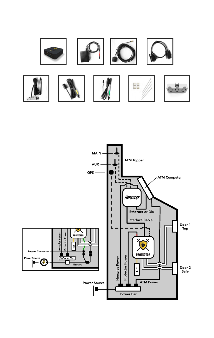
Equipment Supplied
Protector GPS GPS Antenna Interface CablePower Supply
(2) Door Sensor
Cables &
Adhesive Strips
Tilt/Vibration
Sensor Cable &
Velcro Adhesive
Strip
ATM Conguration
With Restart
Restart
Connector
Cable
4” Cable Ties
& Adhesive Tie
Downs
3 Outlet Tap
[email protected] 1-800-561-8880
Page 3

Connecting the Protector GPS
Step 1
If powered on, disconnect the Hercules from its power
source.
Step 2
Connect the Hercules to the Protector with the interface
cable.
Step 3
Connect the GPS antenna to the Protector by screwing the
SMA connector into the antenna jack of the Protector.
In a discrete location, near the top of the asset, and not
within a metal enclosure, mount the GPS antenna using the
magnetic mount, a minimum of four inches away from the
MAIN and AUX antennas of the Hercules.
Note: Metal enclosures hinder the GPS antenna from
signaling the Protector’s GPS position.
Step 4
Mount the cable-free, magnetic door sensors to the swing
side of the desired doors to be monitored.
Step 5
Mount the sensor ends of the door sensor cables opposite
the cable-free magnetic door sensors, a maximum of half an
inch apart when the doors are closed.
Step 6
Insert the connector end of the door sensor cables into the
desired door ports of the Protector.
Note: When powered on, and the door sensors are within
a half inch of each other, the door sensor LEDs will be lit
green and when the doors are open the LEDs will be lit
red.
Step 7
Mount the sensor end of the tilt/vibration sensor cable to an
inside, vertical surface using the Velcro adhesive strip.
Note: Tilt sensor orientation affects alarm sensitivity.
Vertical = High Sensitivity
Horizontal = Medium Sensitivity
Upside Down = Low Sensitivity
[email protected] 1-800-561-8880
Page 4

Step 8
Insert the connector end of the tilt/vibration sensor cable
into the tilt port of the Protector GPS.
When powered on, the tilt LED will be lit green. When tilting
or vibration is detected the tilt LED will be lit red.
Step 9
Connect the power supply cables to the Hercules and the
Protector GPS respectively and connect them into a power
source.
Note: Do not plug the Protector GPS into a backup battery
power supply. Doing so will prevent the power cut alarm
from being triggered. If installing with the Restart, connect
the Restart to the Protector GPS using the restart cable.
Plug the Protector GPS and Hercules into the 3 outlet tap.
Plug the 3 outlet tap into the white, unswitched outlet
of the Restart. Plug the ATM power cable into the black,
switched outlet of the Restart, then plug the Restart into a
power source.
Step 10
Secure the Protector GPS by placing it in a discrete
location (E.g. inside the safe) within the asset, to reduce the
likelihood of it being discovered by others.
FCC Statement: This equipment has been tested and
found to comply with the limits for a Class B digital
device, pursuant to Part 15 of the FCC Rules. These
limits are designed to provide reasonable protection
against harmful interference in a residential or commercial
environment. This equipment generates, uses, and can
radiate radio frequency energy and, if not installed and
used in accordance with these instructions, may cause
harmful interference to radio communications. However,
there is no guarantee that interference will not occur in a
particular installation. If this equipment does cause harmful
interference to radio or television reception, which can be
determined by turning the equipment off and disconnecting
the internal battery, the user is encouraged to try to correct
the interference by one or more of the following measures:
(1) Re-orient or relocate the antenna, (2) Increase the
separation between the equipment and the receiver, (3)
Connect the equipment into an outlet or a circuit different
from that to which the receiver is connected, and (4)
Consult DPL or an experienced radio/TV technician for help.
Warning: Changes or modications not expressly approved
by DPL could void the user’s authority to operate the
equipment. Declaration: This equipment contains a Trimble
Condor C1919C GPS receiver module source.
[email protected] 1-800-561-8880
 Loading...