

Page 1
Quick Install Guide
REV # – DPL500ATMLTER2
Page 2

Table of Contents
Equipment Supplied
Connecting the Hercules
ATM Conguration
RMS Conguration
Specications
1
2
4
5
10
Page 3
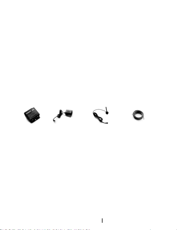
Equipment Supplied
Hercules Power Adapter 2 Antennas Ethernet Cable
If any of the above items are missing please
contact DPL.
Before You Begin
Activate the Hercules (if not pre activated) a
minimum of two-days before installation by
logging in to the Hercules Portal at hercules.
dplwireless.com or by contacting DPL technical
support at 1-800-561-8880 or by email at
[email protected] 1-800-561-8880
1
Page 4

Be prepared to provide the following
information:
• Company name • Connectivity type (dial up or IP)
• Email address • Transaction processor*
• Hercules serial number • Message format to be used
†
*If the ATM is new to you, contact your
transaction processor to set it up. †For IP only
ATMs. Message format supplied by transaction
processor.
Connecting the Hercules
Step 1
Connect the antennas to the Hercules by
screwing the SMA connectors into the antenna
jacks of the Hercules (hand tight).
Secure the magnetic mounts at the base of the
antennas to a metallic surface or near the top
of the ATM terminal in a vertical orientation
(top of antenna’s pointing upward).
2
Page 5
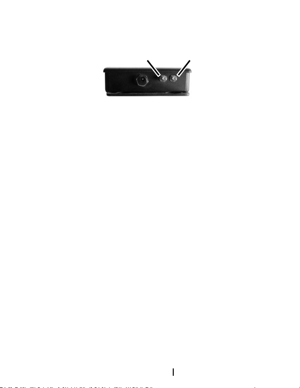
MAIN AUX
The MAIN antenna, connected closest to the
power jack (pictured above) should be placed
in the most ideal location. The AUX antenna
should be placed a minimum of four inches
away or more from the MAIN antenna. Ensure
the antennas are placed away from electronics
or other metallic objects that may cause signal
interference.
Step 2
Connect the required communication cable
(ethernet or telephone) from the ATM to the
Hercules.
Step 3
Plug the power adapter into the Hercules and
then plug it into an AC outlet. Verify the green
Power indicator is lit on the Hercules.
3
Page 6

Step 4
Verify the green ATM and SRVC indicators
are lit indicating the Hercules is successfully
communicating with DPL’s data centers.
Step 5
Place the Hercules inside the safe of the ATM
and lock the safe.
ATM Conguration
Depending on your chosen connectivity type,
congure the ATM using the settings below:
IP
ATM
• Enable DHCP
or
• Static Settings:
• IP Address: 192.168.0.55
• Subnet: 255.255.255.0
• Gateway: 192.168.0.52
4
Page 7

Host
• Disable URL
• Host Address (1&2): 192.168.0.52
• Host Port (1&2): 8000
• Disable SSL
• Disable Permanent TCP/IP
Dial Up
ATM
• Modem speed: 1200 baud or 2400
baud
Host
• Host number: 555-0120
RMS Conguration (Optional)
2-Way conguration is available for ATMs that
use remote management software (RMS).
Step 1
Congure ATM
5
Page 8

Dial Up
• RMS telephone number: 555-0155
• Modem baud rate: 14,400 or less
• Note what your baud rate is and any other
protocol settings. The Hercules+ supports
v.22bis, v.32 and v.32bis (2400 – 14,400) baud
rates for 2-Way.
IP
• RMS Server IP: 192.168.0.53
Note: The above settings are DPL’s standard
conguration. If these settings are not available
in your ATM, contact DPL technical support.
Step 2
Contact DPL technical support to assist
with RMS server conguration and software
installation.
6
Page 9

FCC Statement
Antenna Placement: Place antenna so a
minimum of 8 inches is maintained between it
and any person to limit RF exposure to within
FCC guidelines. Note: This equipment has
been tested and found to comply with the
limits for a Class A digital device, pursuant
to Part 15 of the FCC Rules. These limits are
designed to provide reasonable protection
against harmful interference in a commercial
environment. This equipment generates, uses,
and can radiate radio frequency energy and, if
not installed and used in accordance with these
instructions, may cause harmful interference
to radio communications. However, there is
no guarantee that interference will not occur
in a particular installation. If this equipment
does cause harmful interference to radio or
television reception, which can be determined
by turning the equipment off and on, the user
is encouraged to try to correct the interference
by one or more of the following measures: (1)
Re-orient or relocate the antenna, (2) Increase
7
Page 10

the separation between the equipment and
the receiver, (3) Connect the equipment into an
outlet or a circuit different from that to which
the receiver is connected, and (4) Consult DPL
or an experienced radio/TV technician for help.
Warning
Changes or modications not expressly
approved by DPL could void the user’s
authority to operate the equipment.
Declaration
This equipment contains a radio module
Gemalto ELS61-US or Gemalto ELS31-V. Refer
to product label for FCC / ICAN numbers.
Electronic Devices
Most modern electronic equipment is shielded
from radio frequency (RF) signals. However
certain electronic equipment may not be
shielded against the RF signals from the
Hercules (LTE/HSPA) wireless modem. This
should be considered before installing in
8
Page 11

sensitive areas such as Medical Facilities and
facilities that ban the use of Digital Cellular
Phones.
Trademarks and Copyright
Hercules/Hercules+ is a trademark of DPL. All
rights to this publication are reserved. No part
of this publication may be copied, reproduced,
transmitted or stored in any form or by any
means (including electronic, mechanical,
photocopying, recording, or otherwise) without
prior written permission from DPL.
Disclaimer
While all reasonable care has been taken to
ensure that the description, opinions and text
are accurate and workable, DPL does not
accept any legal responsibility or liability to
any person, organization or other entity for
any direct loss, consequential loss or damage,
however caused, that may be suffered as
a result of the use of this publication or
equipment.
9
Page 12

Specications
Warranty 5 years parts and labour. Details available
from DPL.
Dial In Interface Central Ofce POTS Line, RJ-11, 2400
baud v.22bis or 1200 Baud
Ethernet Port Supports 10/100T speeds and straight or
crossover cables
Interface Port Custom port for Protetcor / Restart
harness which is optional
Protocols Supported VISA-2, Security Encoding: Triple DES
Network Services 4G Data over LTE network with ability to
fall back to
3G/HSPA (carrier dep.)
Power Supply Output 12VDC, 2A, Center Positive, 5.5mm x
2.1mm
Power Supply Input 100-240VAC, 50-60 Hz, 1.0 A Max
Dimensions (h w d) 3.8 x 12.2 x 14.5 cm (1.5 x 4.8 x 5.7
inches)
Operating Temp -10 to 45 °C (14 to 113 °F)
Weight 1.1 kg (2.4 lbs.)
10
Page 13

 Loading...