

Page 1
USER Manual
Applications
!May be used as part of a wireless security
system.
!Can be used as a baby sitter to watch your baby
constantly from anywhere in your home.
!Monitor and record a meeting from another
room.
!Use multiple receivers for broadcasting to
Features
!7 selectable channels help prevent any
!Easy <plug and play> installation within
minutes.
!Crystal - clear Audio and Video signals.
Installation
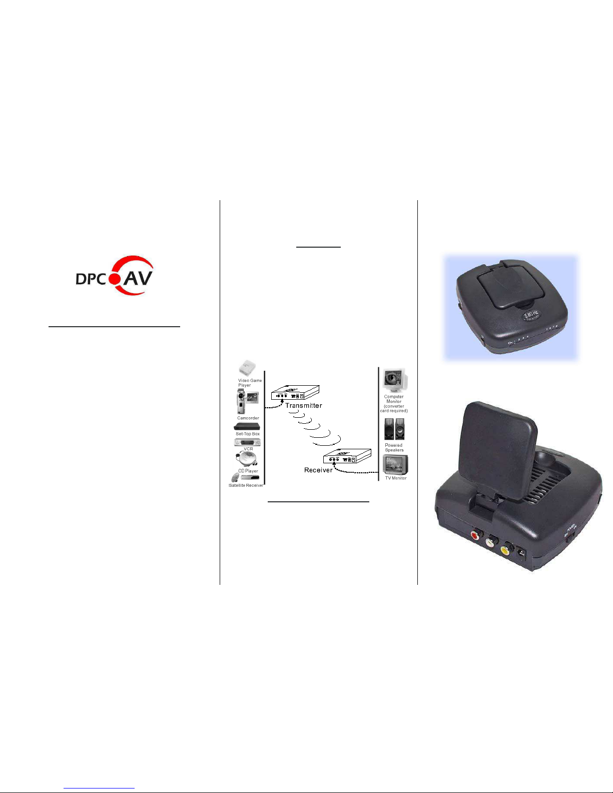
Possible A/V sources are: The A/V display Units are:
VCR TV set
TV set Monitor
Camcorder
Security Camera
Computer
Wireless Cable Box
Channel switch selection
The channel switch is located at the side of the
Set to receive a specific channel. Both the
transmitter and receiver need to have the
channel switch set to the same channel. If there
is interference on the reception, change both the
transmitter and receiver channel setting to a
different channel.
Introduction
technology. It is compatible with Airwave 5.8GHz
interference.
equipment.
The 5.8GHz A/V receiver uses advanced RF wireless
receiver. (See photo A.)
wireless audio-video (A/V) transmitters.
!
video applications.
I
deal for Ham
rad
io
AT
V, rob
o
tics, and
m
odel
numerous wireless video locations.
Works with all kinds of audio and video !
DVR
(O
r
a
cle)
Diversity Controller
AWRX-698
Page 2
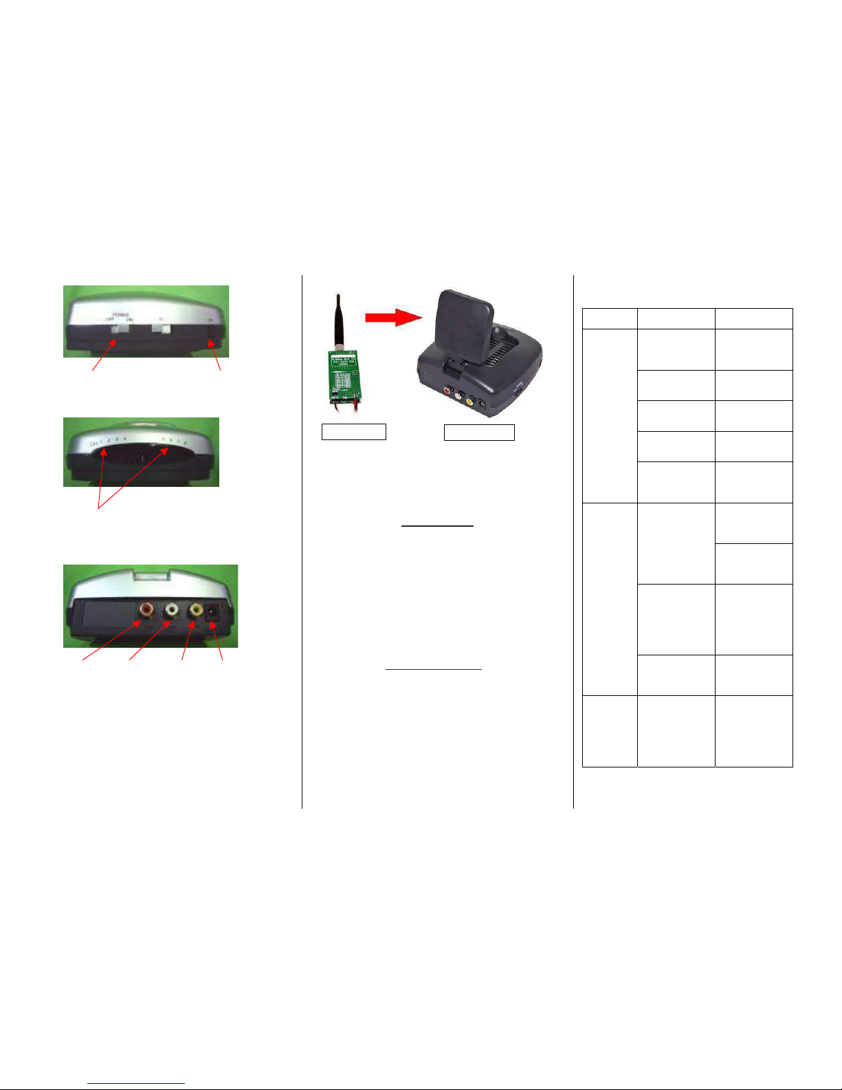
Photo A:
Photo B.:
Channel Indicator: CH1 ~ CH7
Photo C.:
Audio R Audio L Video Power Plug (9V)
Photo D.:
Specification
Receiver:
1. Frequency: 5.725GHz – 5.875GHz
2. Channel: 7 selectable channels
Trouble Shooting
If a problem occurs, first refer to this information before
you take the device for repair.
If you are unable to rectify the fault using the information
given here, contact your local dealer or service specialist.
Under no circumstances should you attempt
to repair the device yourself, as this would
PROBLEM POSSIBLE
CAUSE
REMEDY
The transmission
channels for the
transmitter/receiver
do not correspond.
Set the
transmission
channel on the
transmitter/receiver
The transmission
distance is too
great.
Reduce the
distance.
Connecting cable. Check the
EURO-AV plug
and the cinch plug.
No
picture/sound
transmission
Transmitter or
receiver not
switched on.
Switch on the
transmitter or
receiver
Wrong direction of
patch antenna
Adjust the antenna
to the right
position. See photo
D.
Move the
transmitter or
receiver a few
centimeters
Interference.
Change the
transmission
channel on the
transmitter/receiver
Microwave units
and the use of the
so-called ”blue
tooth function”
(W LAN) on mobile
phones or
notebooks.
Change channel to
find better channel
to receive.
Poor
picture/sound
quality
Infrared module. Check the
connection and
position of the
infrared module.
Transmitter
4. Audio: Line level, 10K ohms
5. Antenna: Built in antenna
6. Power supply: DC 9-12V
3. Video: NTSC or PAL, 1V / 75 ohms
Power Switch Channel select switch
(Press)
Shown above is the Patch antenna orientation
Receiver
Copyright 2009
www.dpcav.com
void the warranty.
 Loading...