

Page 1
Two-Channel Hi-Voltage
Microphone Amplifier
Type HMA4000
User’s Manual
Page 2

Contents
Two-Channel Hi-Voltage Microphone Amplifier
Type HMA4000
Technical Description . . . . . . . . . . . . . . . . . . . . Page 3
Full Specifications. . . . . . . . . . . . . . . . . . . . . . . Page 7
Recommended Settings . . . . . . . . . . . . . . . . . . . Page 9
Changing the Main Fuse on HMA4000 . . . . . . Page 11
Care of HMA4000 . . . . . . . . . . . . . . . . . . . . . . . Page 12
Service and Repair . . . . . . . . . . . . . . . . . . . . . Page 13
Warranty . . . . . . . . . . . . . . . . . . . . . . . . . . . . . . Page 13
CE Standard . . . . . . . . . . . . . . . . . . . . . . . . . . . Page 13
User’s Manual
Page 3
The DPA Microphones High-Voltage Microphones Types 4003, 4004 and
4012 are powered via the Two-Channel High-Voltage Microphone Amplifier
HMA4000, which supplies 130V to their build-in preamplifiers giving the
microphones excellent SPL handling capability. But the HMA4000 is not only
a power supply unit, it is also a microphone amplifier with outstanding
specifications:
The Microphone Amplifier
The HMA4000 uses state-of-the-art, low-noise operational amplifiers from
Analog Devices ‚ in the input stages. Each channel input features
independently switchable amplification or attenuation by +20 dB; 0 dB
or -20 dB corresponding to a maximum input voltage of 1,6 V; 16 V or
160 V peak. The dynamic ranges in the three attenuator settings are:
126 dB(A)THD=0,5% in setting +20 dB; 134 dB(A)THD=0,5% in setting
-20 dB and 140 dB(A)THD=0,5% in setting 0 dB. The HMA4000 is
completely transformerless, which gives the microphone amplifier an
excellent frequency range from 10 Hz to 200 kHz (-1 dB). Furthermore,
there is only one capacitor (a high quality polycarbonate condenser) in the
signal path in the HMA4000. The HMA4000 has a channel separation better
than -90 dB measured in worst case with the attenuator setting.
Featuring both electronically balanced and single ended line-level outputs,
the HMA4000’s impedance converters can drive up to 300m of cable.
Both input channels are single ended and it is recommended to use DPA
Microphone cables such as DAO0130 to keep noise rejection at its optimum.
3
Technical Description
User’s Manual
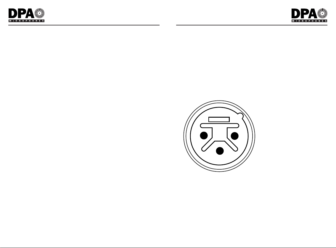
Absolute phase
During the design process attention has been paid to the absolute phase of
the system. Positive going voltage at pin 4 on the modified 6 pin female XLR
input socket will produce positive-going voltage at pin 2 on the standard 3-pin
male XLR output socket. (Pin 1: Ground; Pin 2: Signal +; Pin 3: Signal return.
See Fig. 1 and Fig 2 for pin designation of the input and output sockets).
Fig. 1. External view of the output
socket of the HMA4000.
4
Technical Description
User’s Manual
Page 4

The power supplies
The HMA4000 supplies 130 VDC to the built-in preamplifiers of the HighVoltage Microphones Types 4003, 4004 and 4012 via pin 2 on the modified
6 pin input socket on the HMA4000, giving the microphones an extended
SPL handling capability. Furthermore the HMA4000 is prepared for powering
future microphones from DPA Microphones: 200 VDC on pin 5 and 6,3 VDC
on pin 6. See Fig. 2.
Fig. 2. External view of the modified
6 pin input socket of the HMA4000.
Mains Supply
The HMA4000 can be run from either 110 V/ 60 Hz or 230 V/ 50 Hz external
powering, and automatically switches to the appropriate power setting when
connected. The AC mains supply for the HMA4000 is connected via the 3 pin
IEC 320 socket which accepts cable DAN0010 (supplied). Maximum power
5
Technical Description
User’s Manual
1
2
3
4
5
6
consumption is 15 W. The mains fuse needs only to be checked if the power
indicator on the front of the HMA4000 fails to light. See Fig. 7 and Fig. 8 for
how to change mains fuse.
Optional accessories - Cables
Special high-voltage microphone cables can be obtained as optional
accessories for the HMA4000. The standard DAO0130 High-Voltage
Microphone Cable is 5m long and is equipped with a modified 4 pin female
XLR-connector in the microphone end and a modified 7 pin male XLRconnector in the output end, where it connects to the HMA4000. The
microphone cable used in the DAO0130 uses oxygen free copper in both
conductors and screen. The tightly woven screen has 98% coverage and
therefore has an extremely efficient noise rejection. Special lengths of highvoltage microphone cable up to 20m can be ordered. Please contact your
local DPA Microphones representative if you require special cable lengths.
Optional accessories - HTP4000 Phantom Converter
The HTP4000 High-Voltage To Phantom Converter connects to the input
socket of the HMA4000 and converts the high-voltage microphone input
channel to a P48 microphone input channel of extremely high quality. The
HTP4000 uses a standard 3 pin female XLR-connector on the audio input
(see Fig 1 for pin configuration), and a modified 7 pin male XLR-connector
where it connects to the HMA4000. It is transformerless and accepts both
electronically and transformer balanced microphone signals. Using standard
DPA microphones 4006, 4007 or 4011 with the HMA4000 and the HTP4000
the absolute phase is preserved (see “Absolute Phase”).
6
Technical Description
User’s Manual
Page 5

Dimensions:
200mm x 133mm x 52mm
Weight:
1.85kg
Spareparts Included:
DAN0010 Power Cable
2 x DVF0250 250mA Slow-Blow Fuse
For use with:
Standard Microphones
3529 A-B Stereo Kit, 130V
4003 Omnidirectional Microphone, 130V
4004 Hi-SPL Omnidirectional Microphone, 130V
4012 Cardioid Microphone, 130V
Accessories Available:
Connection Adapters
HTP4000 Converter: 130V to P48
PCC4000 Passive Converter: P48 to 130V
Cables
DAO0130 130V Microphone Cable, 5m (Type HMA4000)
8
Technical Description
User’s Manual
Frequency range:
10Hz to 200kHz (+0dB / -1dB)
Dynamic range:
Attenuator
HMA4000 HTP4000
Setting
+20 dB 126dB(A) 114dB(A)
0 dB 140dB(A) 128dB(A)
-20 dB 134dB(A) 122dB(A)
No channels:
2
Channel crosstalk:
<-90dB (0Hz to 20kHz)
Attenuation:
+20dB, 0dB, -20dB
Equivalent noise level A-weighted:
Pin 2-1: <0.4µV, Pin 2-3: <0.6µV
(measured in setting: +20dB)
Equivalent noise level CCIR 468-1:
Pin 2-1: <1.8µV, Pin 2-3: <3.0µV
(measured in setting: +20dB)
Cable drive capability:
<300m
Max input voltage:
1.6V (+20dB); 16V (0dB); 160V (-20dB)
Max output voltage:
32V peak (16V peak for single ended operation)
Input impedance:
30 kOhm
Output impedance:
2 x 50 Ohm
THD:
<-75dB (0Hz to 40kHz)
Min output current:
2 x 55mA
Max output DC offset:
±20mV
Min load impedance:
600 Ohm
Input connector:
Via modified 6 pin female XLR-socket. Accepts cable DAO0130.
Switchable +20dB; 0dB or -20dB ±0.5dB
Output connector:
Via standard 3 pin male XLR-socket
Operating temperature range:
-10°C to +55°C (+14 to 131°F)
Mains voltage:
100Vac - 127Vac and 200Vac - 240Vac, 50Hz and 60Hz Mains Supply
Power consumption:
Maximum 15W
7
Technical Description
User’s Manual
Page 6

To choose a suitable setting of the input attenuator on the HMA4000 it is
recommended to estimate the peak and average sound pressure levels
encountered by the microphone during the recording.
Fig. 3. Recommended HMA4000
setting with Type 4003.
9
Recommended Settings
User’s Manual
Fig. 6. Recommended HMA4000
setting with Type 4012.
Fig. 4. Recommended HMA4000
setting with Type 4004.
Recommended Settings
User’s Manual
Fig. 7. Recommended HMA4000 setting with Type 4006 and HTP4000.
Fig. 8. Recommended HMA4000 setting with Type 4007 and HTP4000.
Fig. 9. Recommended HMA4000 setting with Type 4011 and HTP4000.
10
Page 7

11
Changing the Main Fuse on HMA4000
User’s Manual
The Type HMA4000 is fitted with a 250 mA slow blow fuse (DVF0250).
The fuse is rated to give adequate protection at both 110 VAC and 230 VAC.
Only the correct replacement must be fitted.
WARNING! Disconnect the HMA4000 from the mains supply
before removing the instrument casing.
1.
The mains fuse holder is located on the printed circuit board of the
HMA4000. To gain access to it, the front and rear face panels of the
HMA4000 should be removed by pulling the top and bottom edges of
the clip on frame outwards (as shown in Fig. 7).
2.
Unscrew the two retaining screws on the metal casing of the HMA4000
3.
Gently pull out circuit board.
4.
Remove the Mains Fuse with a screwdriver and insert a new
Mains Fuse likewise.
Fig. 7.
12
Care of the HMA4000
User’s Manual
Care of the HMA4000
The operating temperature range of Type HMA4000 Two-Channel HighVoltage Microphone Amplifier is from -10 °C to +55 °C (+14 °F to +131 °F).
The instrument is protected against internal overheating by a self-resetting
thermal switch which operates at 125 °C ±5 °C.
The HMA4000 is extremely robust. It is insensitive to vibration and will
withstand mechanical shock. Therefore the HMA4000 is well suited for
placement on the stage or the studio floor.
Page 8

Service & Repair
Products from DPA Microphones are extremely stable and there should not
be any significant change in the specifications with time and use. If,
however, you are not totally satisfied with the characteristics exhibited by
these products, then contact your nearest DPA Microphones representative
for further details of service and the repair facilities that are available. DPA
Microphones has a maximum seven working days in-house service policy,
guaranteeing that no more than seven working days will elapse from the day
we receive the item for service to the day we are ready to return it to you.
Your satisfaction is our satisfaction.
Please contact DPA Microphones for your nearest representative on
tel. +45 48 14 28 28 or fax +45 48 14 27 00.
Warranty
All products from DPA Microphones are covered by a limited warranty on
both their mechanical functionality and their documented specifications. We
are so confident of the quality of these products, that this warranty is valid
for one year from the date of purchase, as long as the items are not directly
mistreated or abused. In case of a warranty claim, your invoice is your
warranty registration.
CE Standard
The CE-mark guarantees all products conform with relevant standards
approved by the European Community. The products described in this User’s
Manual comply with current relevant standards when used with cables from
DPA Microphones.
EMC Directive: 89/336/EEC, amended by 92/31/EEC and 93/68/EEC
Low Voltage Directive: 73/23/EEC, amended by 93/68/EEC
13
Service & Repair
User’s Manual
Page 9

Gydevang 42-44 • DK-3450 Alleroed • Denmark
Tel: +45 4814 2828 Fax: +45 4814 2700
www.dpamicrophones.com
email: info@dpamicrophones.com
 Loading...