

Page 1

Introduction
To ensure optimal performance of your
DPA Miniature Microphone, please follow
the simple care and maintenance ins truc-
tions below.
Miniature Microphones from DPA are
designed to be ver y resistant to humidity,
moisture and sweat. Highly resistant mate-
rials like gold plated stainless steel, and fea-
tures like the double-vent-protection-sys-
tem are used in cons truction of the micro-
phones, to avoid damage by hostile fluids. In
any case, it is still a good idea to keep the
Miniature Microphones away from any kind
of unnecessary exposure to water and
cleaning fluids and to keep the microphone
element dry at all times.
1. Cleaning guide
The cable and protection grid are t he only
parts that may be cleaned if necessar y.
The protection grid is permanently f ixed
and protects the microphone element
inside. Do not attempt to remove the pro-
tection grid under any circumstances.
Do not use any kind of cleaning fluid other
than distilled water. Use of ultra-sonic bat hs
must be avoided. Avoid all kinds of spray or
fluids, which contain chemical components
to remove static electricity on or close to
the microphone as this could cause dam-
age to the electret layer.
When mounting the Miniature Microphone
directly on the skin of a perfor mer, care
should be t aken to avoid sweat from run-
ning directly into the microphone. If the
microphone gets filled up with water or
sweat it will not be damaged, but possibly
turn deaf while the water is captured inside
the microphone, behind the protection grid.
Remove the water by shaking the micro-
phone or dr ying it with a piece of lint free
cloth.
Note: If the microphone has been
exposed to water or sweat it must be
left to dry out to recover its original
specifications. Drying out the
Miniature Microphone between exposures to humidity will also help to
extend its lifetime. Leaving the microphone with the power on will speed up
the drying process, as the built-in preamplifier will gently heat up the microphone (idle power ~2 mW).
Tip: In order to save batter y power on the
belt pack transmitters while drying out the
microphone, it is a good idea to use a P48
Phantom Power Adapter (DAD6001).
1.1 Cleaning the microphone grid
During use in environments where the
microphone is exposed to make-up or dusty
materials, the grid may get clogged up. If
needed, clean the grid using a soft clot h
and distilled water only.
1
MANUAL 4071 -2 13/05/03 9:21 Side 1
Page 2
3
2
2.3 Correct treatment of the microphone cable
The cable is usually longer t han required for
its actual purpose. Ensure t hat superfluous
cable is wound up in soft loops (preferably
6-8 cm in diameter). Avoid ’kink s’ in the
cable. Exposing the cable to stretching
beyond its specifications or stressing it by
winding it tightly over sharp edges will
reduce the microphone’s operational life
Tip: Handling noise from the cable can be
decreased by up to 30dB by making a loose
loop in the cable, as close to the micro-
phone element as possible. The DMM0008
Miniature Clip, double lock, is designed for
this mounting technique.
Tip: The place where t he cable enters the
MicroDot connector will sometimes be
exposed to excessive stress and af ter long
term heavy-duty use, the cable might show
signs of wear at t his point. As a preventive
maintenance procedure, it may be advis-
able to replace the connector in this
instance. Contact t he nearest DPA
Microphones representative for mainte-
nance advice or assist ance.
2.4 Correct use of adapters and
MicroDot connectors
To provide users wit h safe and compact
mounting of connectors, all Miniature
Microphones from DPA are fitted with t he
MicroDot connector as standard. A broad
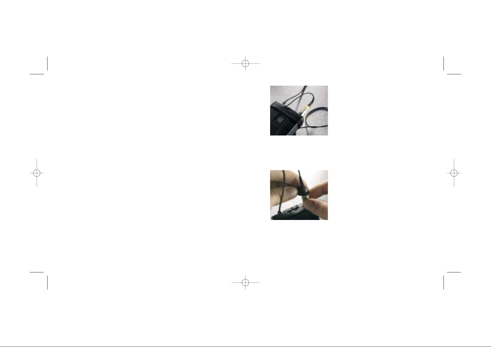
Correct way to wind up the cable
of the Miniature Microphone.
Please note the slack af ter the connector.
A connector tightening tool is
supplied with each adapter
1.2 Cleaning the microphone cable
Residue from tape, glue or make-up on the
cable must be removed af ter use. Leaving
these substances on the cable over longer
periods of time may etch into the cable
jacket and will make the cable more suscep-
tible to breaks. The cable can easily be
cleaned using organic oil (e.g. olive oil) or
lukewarm, distilled water.
Do not bend the cable or rub it harshly
since this may stress the inner cores of the
cable and cause them to break over time.
2. Correct use of the Miniature
Microphone
It is important to observe the following
guidelines concerning the daily use of the
microphone.
2.1 Description of presence boost and
frequency response
The type 4071 has a fixed microphone grid
with a typical 5dB soft boost at 4-6kHz.
This so-called “presence area” is the range
where the human ear is most sensitive and
is also the range of speech intelligibility, clar-
ity and definition. When a microphone is
placed on the chest for example, clarity
seems to be lost. Most engineers will com-
pensate for this by having a presence
boost on an equalizer in t he following audio
path, to make the voice “cut through”.
The Type 4071 with presence boost will
make use easier and quicker and will intro-
duce less noise and dis tortion than any EQ
will because the boost is done acoustically, at
the microphone diaphragm. An acoustic lo-
cut has been incorporated in the capsule so
the built-in preamp and the perhaps follow-
ing wireless system will have much larger
headroom. When recording voices, from
microphone placement on the per former’s
body, no frequency below 100 Hz is relevant.
For this reason, the airing vent in the capsule
has been specially designed to make the fre-
quency response 2dB attenuated at 100Hz,
with a 3dB per octave roll off. Outdoor
recordings can introduce unwanted wind
rumble. The lo-cut feature will reduce the low
frequency part of t he wind rumble.
2.2 Correct treatment of the microphone element
The diaphragm in the microphone element
is the most sensitive part of t he unit and as
emphasized earlier, it must be left
untouched to preserve its original charac-
teristics. Do not spray any substances such
as hair spray directly into the microphone
and avoid getting make-up or paint on the
microphone element and housing.
Tip: In lapel or tie placement it is recommend-
ed that the microphone grid point away from
the mouth to decrease breathing noises
caused by the mouth or nose of the per-
former. The microphone element is com-
pletely omnidirectional at all frequencies, so
this method will not colour the sound.
MANUAL 4071 -2 13/05/03 9:21 Side 2
Page 3
54
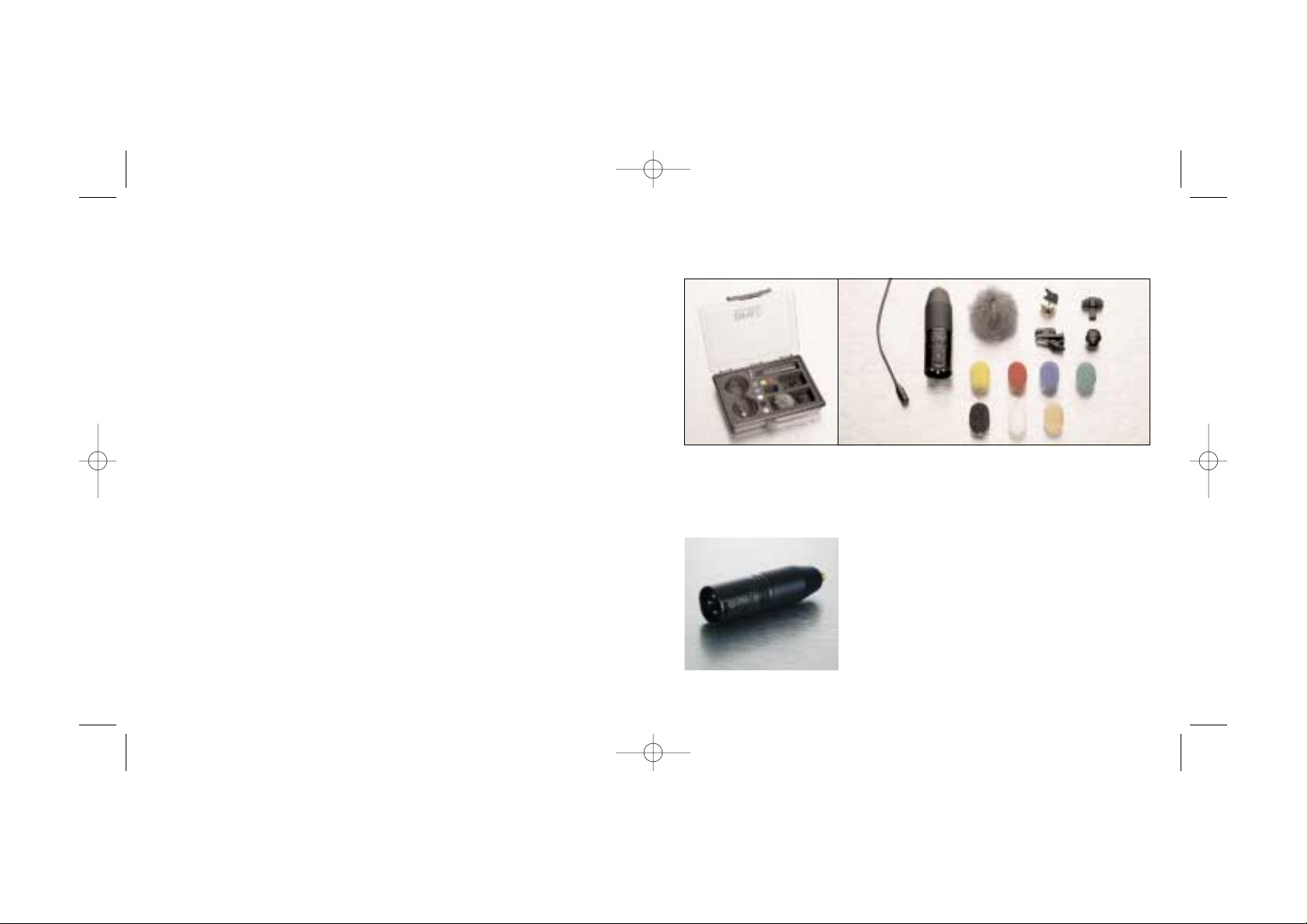
EMK4071 ENG/EFP MICROPHONE KIT
Also available as DAK4071-E excluding microphone and adaptor.
DAD6024 XLR adaptor with mid range
attenuation
3. EMK4071 ENG/EFP Microphone Kit
This kit is made for ENG/EFP use, when the
microphone is allowed to be visible. The kit
is delivered in a sturdy, hard case with a
transparent lid. It contains a 4071-BM
Miniature Microphone and the following
accessories:
Adaptor: MicroDot to 3-pin. XLR (P48)w.
Mid Range Attenuation (DAD6024)
Designed for microphone placement on the
human body. When placing a microphone on
a performer’s chest, an acoustic lower
midrange boost will occur resulting in a
"muddy" and indistinct sound, compared to a
free frontal placement. This adapter pro-
vides a 3dB attenuation at 800Hz for added
clarity when using a Miniature Microphone.
range of connection adapters is offered as
optional accessories for most VHF and UHF
systems for professional use. The adapters
are ultra-compact and will in most cases
take up no more space than t he original
connectors. With each adapter comes a
connector-tightening tool, which should be
employed whenever the MicroDot connec-
tor needs to be tightened safely onto the
adapter for long periods of time.
Never attempt to loosen or tighten the con-
nector by the cable or its strain relief.
Despite the use of Kevlar, the cable might
be damaged if twisted wit h excessive
force. Tighten the MicroDot using finger
torque or the recommended tightening tool
only. Do not use glue.
Do not mount any other connector onto
the cable than t he standard MicroDot con-
nector from DPA Microphones. The DPA
MicroDot connector is specially designed
for use with the Kevlar reinforced cable,
ensuring the maximum possible tensile
strength in the design. In case of failure,
MicroDot spare parts, assembly tool and
assembly guide can be acquired.
Various wireless systems require the use of
electronic components inside the adapter to
optimize the signal level, t he DC-offset filter-
ing and powering of the built-in microphone
preamplifier. Using the adapters from DPA
ensures the correct electronic circuit with
the listed types of wireless systems at all
times. Do not attempt to employ non-stan-
dard adapters or connectors as you might
damage the microphone preamplifier.
MANUAL 4071 -2 13/05/03 9:21 Side 4
Page 4

76
Miniature Mesh
Miniature Windjammer
Miniature Windjammer
(DUA0571)
Miniature Windjammer for use in heavy
wind. The windjammer fur coat is sewn to
the mesh. This will make it totally insensitive
to handling noise from any possible friction
between the two materials. Please note
that the presence boos t will be vir tually
unaffected by the windjammer, but that
the high frequency roll of f will set in a little
earlier.
Attachment: Gently place t he windjammer
over the microphone grid until it cannot
move any further.
Miniature Mesh
(DUA0572)
Miniature Mesh for slight wind- or pop
reduction from a speaker’s voice or any
other turbulence that can cause the
diaphragm to disperse.
Attachment: Gently place t he mesh over
the microphone grid until it cannot move
any further.
Miniature Windscreens
Miniature Clip, Double Lock
Miniature Holder, Single Pin
Miniature Holder, Single Pin
(DMM0006)
Ultra-small single pin holder for mounting on
the chest of a speaker quickly and easily.
The pin has a lock that ensures maximum
mounting stability, and it is specially
designed for use on rat her thick clothes like
sweaters, sweatshir ts and jackets.
Miniature Clip, Double Lock
(DMM0008)
Clip for quick and easy mounting on the
chest of a speaker. The double lock feature
allows for attachment with a loop on the
cable (ref. section 2.3).
Miniature Windscreens (7 colours)
(DUA0570)
The windscreens are made of foam. The
size and construction of the foam ensure
that the windscreen does not attenuate
the higher frequencies more than the toler-
ance field of the microphone frequency
response and simultaneously provides pro-
tection from wind and pop-noises. The size
of the windscreen makes it discreet in all
applications.
MANUAL 4071 -2 13/05/03 9:21 Side 6
Page 5

98
Double-sided Tape for DMM0009
Miniature Concealer
Miniature Double Pin, Black
Miniature Double Pin, Black
(DMM0002-B)
Holder for quick and easy mounting on the
chest of a speaker. The double pin ensures
maximum mounting s tability and makes it
possible to fit the microphone even on
T-shirts and sweaters.
Miniature Concealer
(DMM0009)
Whenever the 4071 Miniature Microphone
needs to be hidden on a performer, the
DMM0009 comes in useful. Simply place
the 4071 in the opening on the backside of
the holder. The microphone is now secured
from friction noise from clothing because
the microphone (including the grid) is hid-
den and the holder itself is smooth. The mic
concealer can be sewn into clothing by
using the 4 buttonholes or it can be f ixed to
any cloth material using the double-sided
tape pads.
Double-sided Tape for DMM0009
10pcs. (ADH0002)
Specially designed and easy to use double-
sided tape pads for the DPA Miniature
Concealer. Store tape away from excessive
heat and light.
Attention: Do not use t hese double-sided
tape pads on leat her, suede or directly on
skin.
FMK4071 FILM MICROPHONE KIT
Also available as DAK4071-F excluding microphone.
4. FMK4071 FILM MICROPHONE KIT
This kit is made for Film or TV production
use, when the microphone is not
allowed to be visible. The kit is delivered
in a sturdy, hard case with a transparent lid. It contains a 4071-BM Miniature
Microphone and leaves room for one or
more connection adaptors.
Also included is:
MANUAL 4071 -2 13/05/03 9:21 Side 8
Page 6

1110
Double-sided Mic Tape
Miniature Mic Tape.
Miniature Mic Tape, 10 pcs.
(ADH0003)
Specially designed self-adhesive pads for
use directly on the 4071. Store tape away
from excessive heat and light.
Attention: Do not use t hese double-sided
tape pads on leat her, suede or directly on
skin.
Double-sided Mic Tape, 10 pcs.
(ADH0004)
Versatile self-adhesive mounting tape, origi-
nally made as toupee t ape.
Store tape away from excessive heat and
light.
Tie Pod
Double-sided Tape for Tie Pod
Tie Pod, 3 pcs.
(DMM0010)
When an actor wears a tie, noise is unavoid-
able from friction between tie and shirt. A
successful placement of the microphone
could be in the knot of the tie wit h the
microphone inside this sof t tie pod with
double-sided tape outside t he pod. The
holder will be fixed, t he tie can be tightened
around it and the microphone grid is hidden
in the pod and will not pick up friction noise.
Tip: To reduce friction noise further, the
Double-sided Mic Tape (ADH0004) included
in this kit can be used to secure the tie to
the shirt.
Double-sided Tape for Tie Pod, 10 pcs.
(ADH0001)
Specially designed and easy to use double-
sided tape pads for the DPA Tie Pods.
Store tape away from excessive heat and
light.
MANUAL 4071 -2 13/05/03 9:22 Side 10
Page 7

1312
5. Specifications
Cartridge type:
Pre-polarized condenser element with verti-
cal diaphragm
Principle of operation:
Pressure
Power supply:
Via the Adapter Sys tem from
DPA Microphones
Frequency range:
100Hz – 15kHz ±2dB with typ. 5dB sof t
boost at 4-6kHz.
Directional characteristics:
Omnidirectional
Sensitivity:
Nominally 6mV/Pa ± 3dB at 1kHz;
-44.4 ±3dB re. 1V/Pa
Equivalent noise level CCIR 468-1:
Typ. 38dB (max. 40dB)
Equivalent noise level A-weighted:
Typ. 26dB(A) re. 20µPa (max. 28dB(A))
Max SPL:
144dB SPL before clipping
Total Harmonic Distortion:
123dB SPL peak (<1% THD);
120dB SPL sine (<1% THD)
Preamplifier:
Output impedance: 30-40 Ohm
Cable drive capability: Up to 300m
Dimensions:
Microphone length: 17mm
Microphone diameter: 5.4mm
Capsule diameter: 5.4mm
Weight: 9g incl. cable and MicroDot connector
Typical on-axis frequency response of DPA 4071.
Miniature Windjammer
(DUA0571)
Miniature Windjammer for use in heavy
wind. The windjammer fur coat is sewn to
the mesh. This will make it totally insensi-
tive to handling noise from any possible fric-
tion between the two materials. Please
note that the presence boost will be vir tual-
ly unaffected by the windjammer, but that
the high frequency roll of f will set in a little
earlier.
Attachment: Gently place t he windjammer
over the microphone grid until it cannot
move any further.
Miniature Mesh
(DUA0572)
Miniature Mesh for slight wind- or pop
reduction from a speaker’s voice or any
other turbulence that can cause the
diaphragm to disperse.
Attachment: Gently place t he mesh over
the microphone grid until it cannot move
any further.
Miniature Mesh
Miniature Windjammer
MANUAL 4071 -2 13/05/03 9:22 Side 12
Page 8

1514
DAD6014 Adapter: Pastega TMA16/ TMU20
(2 wire preset)
DAD6015 Adapter: Vega T-37
DAD6016 Adapter: Beyerdynamic (TS600)/
Trantec
DAD6017 Adapter: AKG PT 40/60/80/81,
Samson UT1L/ VT2LL
DAD6018 Adapter: Pastega TMA16/ TMU20
(3 wire preset)
DAD6019 Adapter: Sony Freedom WRT 805,
Sennheiser Evolution
DAD6020 Adapter: Prostar / Telex UHF-UB12
DAD6021 Adapter: AT ATW-T101 (System
U100), Lectrosonic UHF systems for
low level recordings
DAD6022 Audio-Technica, ATW-751 (1400 Series)
DAD6024 Adapter: MicroDot to 3-pin XLR
(P48) w. Mid Range Attenuation
DAD6025 Adapter: Micron TX700
DAD6026 Adapter: Beyerdynamic TS
500/600, Trantec
DAD6027 Adapter for Beyerdynamic OPUS
100 -200
DAD6028 Adapter: Audio-Technica ATW-T75
(7000 Series)
DAD6030 Adapter: Electro-Voice CSB-1000
(RE1), TELEX
DAD6031 Adapter: Mipro ACT-
707T/TE/TM/TS
DAD3050 Adapter: TOA WM360 (for low DC
Microphones)
DAD3051 Adapter: Ramsa WX-RP410 (for low
DC Microphones)
Miniature Power Supplies
MPS6010 Miniature Batter y Supply, 2-channel,
3-pin XLR
MPS6020 Miniature Batter y Supply, 2-channel,
Phono
MPS6030 Miniature Batter y Supply, 2-channel,
Mini-Jack
MPS6040 Miniature Batter y Supply, 2-channel,
1/4 in. Jack
Cables
DAO6005 Miniature Microphone Cable, 3.5m
DAO6010 Miniature Microphone Cable, 10m
DAO6020 Miniature Microphone Cable, 20m
Cases & Boxes
DAK4060 Accessory Kit for Miniature
Microphones
DAK4071-E Accessory Kit for ENG/EFP
DAK4071-F Accessory Kit for Film
Miscellaneous
DUA6011 Drop Stopper, Black, 10 pcs.
DQA0035 Tool for MicroDot
6. Accessories available
Miniature Holders
DMM0001 Miniature Clip
DMM0002-B Miniature Double Pin, Black
DMM0002-W Miniature Double Pin, White
DMM0003-B Miniature Magnet, Black
DMM0003-W Miniature Magnet, White
DMM0004 Miniature Clip, Small
DMM0005 Miniature Holder, Single Pin, 3 pcs.
DMM0006 Miniature Holder, Single Pin
DMM0007 Universal Surface Mount
DMM0008 Miniature Clip, Double Lock
DMM0009 Miniature Concealer
DMM0509 Miniature Concealer 5 pcs.
DMM0010 Tie Pod, 3 pcs. incl.tape
MHS6001 Microphone Holder for Strings, 1 pcs.
MHS6005 Microphone Holder for Strings, 5 pcs.
Windscreens
DUA0560 Miniature Windscreens, 5 pcs, Black
DUA0561 Miniature Windscreens, 5 pcs, Red
DUA0562 Miniature Windscreens, 5 pcs, Blue
DUA0563 Miniature Windscreens, 5 pcs, Yellow
DUA0564 Miniature Windscreens, 5 pcs, Green
DUA0566 Miniature Windscreens, 5 pcs, White
DUA0567 Miniature Windscreens, 5 pcs, Beige
DUA0570 Miniature Windscreens, 7 pcs, Mix
DUA0571 Miniature Windjammer for 4071
DUA0572 Miniature Mesh for 4071
Adhesive pads
ADH0001 Double-sided Tape for Tie Pod, 25 pcs
ADH0002 Double-sided Tape for Miniature
Concealer, 25 pcs
ADH0003 Miniature Mic Tape, 25 pcs
ADH0004 Double-sided Mic Tape, 10 pcs.
ADH0005 Double-sided Mic Tape, 50 pcs.
Connection Adapters
DAD6001 Adapter: MicroDot to 3-pin XLR (P48)
DAD6001-BC Adapter: MicroDot to 3-pin XLR
(P48) w. Belt Clip
DAD6002 Adapter: Sennheiser BF1083-U/
BF1053-U
DAD6003 Adapter: Sennheiser SK 50/ SK
250/ SK3063
DAD6004 Adapter: Audio Ltd. Tx 2000/ Tx
2020
DAD6006 Adapter: Beyerdynamic
TS42/ TS85/ TS190/ TS900
DAD6007 Adapter: AKG PT 300
DAD6008 Adapter: Sony WRT820/ WRT860/
WRT8
DAD6009 Adapter: Samson CT-2/ TX-3/ UT4/
UT5/ UT6
DAD6010 Adapter: Shure U1/ UT1/ SC1, TOA
WM4300
DAD6011 Adapter: Vega T-66/ T-677 & Shure
U1L
DAD6012 Adapter: Lectrosonic M185
DAD6013 Adapter: Micron TX501.x/ TX502.x
MANUAL 4071 -2 13/05/03 9:22 Side 14
Page 9

7. Service & Repair
Products from DPA Microphones are
extremely stable, and there should not be
any significant change in the specif ications
with time and use. If, however, you are not
totally satisfied with the characteristics
exhibited by these products, contact your
nearest DPA Microphones representative
for further details of service and the repair
facilities that are available. DPA
Microphones has a maximum seven work-
ing days in-house service policy, usually
ensuring that no more than seven working
days will elapse from the day we receive
the item for service to the day we are
ready to return it to you.
8. Warranty
All products from DPA Microphones are
covered by a two-year limited warranty on
both mechanical functionality and docu-
mented specifications as long as the items
are not mistreated, abused or modified in
any way. In case of a warranty claim your
invoice is your warranty registration.
9. CE Standard
The CE-mark guarantees that all products
conform with relevant s tandards approved
by the European Community. The products
described in this User’s Manual comply with
current relevant standards when used with
cables from DPA Microphones. EMC
Directive: 89/336/EEC, amended by
92/31/EEC and 93/68/EEC Low Voltage
Directive: 73/23/EEC, amended by
93/68/EE
Product features and specifications are subject to change without notice.
16
MANUAL 4071 -2 13/05/03 9:22 Side 16
 Loading...