

DP KV6222A, KV6224A Quick Start Manual

STEP X - Name of Step
QUICK START GUIDE
KV6222A, KV6224A
DP KVM
SWITCHES
24/7 TECHNICAL S UPPOR T AT 877.877.2269 OR VI SIT B LAC KBOX.COM
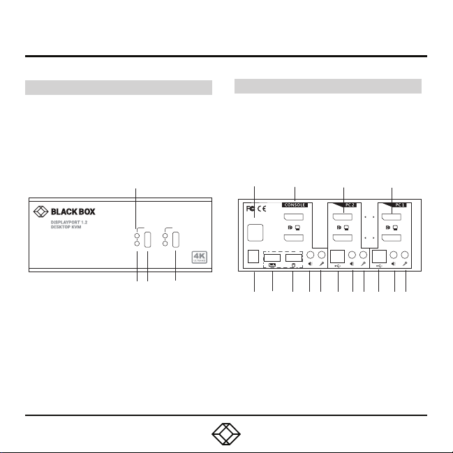
STEP 1A - Front and Back Panel Overview
KV6222 A FRO NT AN D BACK PA NEL S
The dia grams below s how the front an d back
panel s of the KV6222A. Th e table on the ne xt
page describes its components.
KV62 22A Front Pa nel
2
1 2
PC
HUB
1 3 4
NOTE: Only the 2 -port mod el is shown above and
in the ta ble on the next page. The 4-po rt model
looks similar, bu t has 4 ports in stead of 2.
KV6224A F RON T AND B ACK PAN ELS
The K V6224A switc h looks simila r to the
KV62 22A except t hat it has four P C connections
(PC1, PC 2, PC3, PC 4) instead of two.
KV62 22A Back Pa nel
5 6 12 16
DC 9V
HUB
B
A
B
A
7 8 9 10 11 13 14 15 17 18 19

STEP 1B - Front and Back Panel Components
TABLE 1. KV6222A COMPONENTS
NUMBER IN
DIAGRAM
1 Selected Hub Indicator Lights wh en hub is selected
2 Selected PC/Server Indicator Lights wh en PC/Serve r is selected
3, 4 Port S elect buttons Selec ts the port you want to switch
5 (2) USB Type A co nnectors Links to US B devices or hubs
6 (2) DisplayPort connec tors LInks to co nsoles B and A
7 Power connector Links to 9 -VDC power supply
8 USB Type A co nnector Links to keyboard
9 USB Type A co nnector Links to mouse
10 Audio jack Links to co nsole speakers
11 Audio jack Links to console microphone
12 (2) DisplayPor t connector s Links to PC2 DisplayPor t B and A
13 USB Type B c onnector Links to PC 2
14 Audio jack Links to PC2 speaker s
15 Audio jack Links to PC2 micro phone
16 (2) DisplayPor t connectors L inks to PC1 DisplayPort B and A
17 USB Type B connector Links to PC1
18 Audio jack Links to PC1 speakers
19 Audio jack Links to P C1 microphone
COMPONENT DESCRIPTION
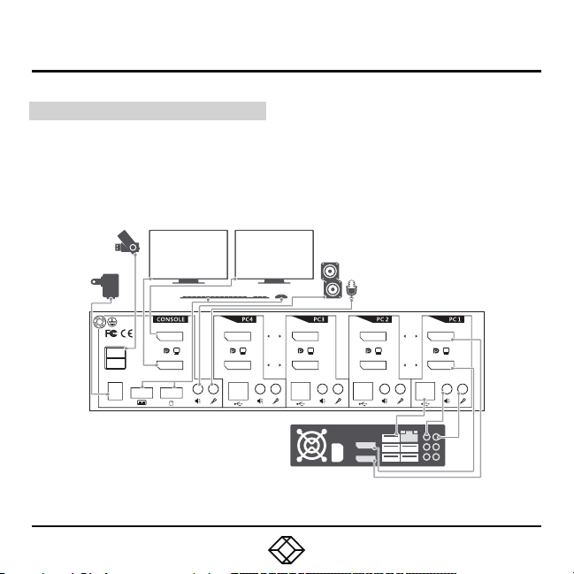
STEP 2 - Connection Diagram
EXAMPLE CONNECTION DIAGRAM
The dia gram illust rated here is an example
of KV62 24A. The ac tual applic ation may var y.
All ill ustrated co mputer, acce ssories and
monitors are no t included in t he package;
they are for reference only.
DC 9V
HUB
B
A
B
A
B
A
 Loading...