

Page 1

STEP X - Name of Step
QUICK START GUIDE
KV6222A, KV6224A
DP KVM
SWITCHES
24/7 TECHNICAL S UPPOR T AT 877.877.2269 OR VI SIT B LAC KBOX.COM
Page 2
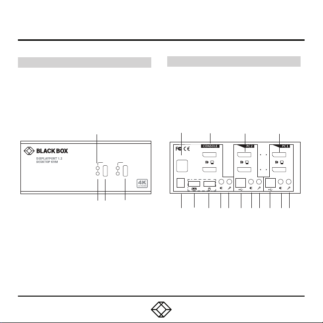
STEP 1A - Front and Back Panel Overview
KV6222 A FRO NT AN D BACK PA NEL S
The dia grams below s how the front an d back
panel s of the KV6222A. Th e table on the ne xt
page describes its components.
KV62 22A Front Pa nel
2
1 2
PC
HUB
1 3 4
NOTE: Only the 2 -port mod el is shown above and
in the ta ble on the next page. The 4-po rt model
looks similar, bu t has 4 ports in stead of 2.
KV6224A F RON T AND B ACK PAN ELS
The K V6224A switc h looks simila r to the
KV62 22A except t hat it has four P C connections
(PC1, PC 2, PC3, PC 4) instead of two.
KV62 22A Back Pa nel
5 6 12 16
DC 9V
HUB
B
A
B
A
7 8 9 10 11 13 14 15 17 18 19
Page 3

STEP 1B - Front and Back Panel Components
TABLE 1. KV6222A COMPONENTS
NUMBER IN
DIAGRAM
1 Selected Hub Indicator Lights wh en hub is selected
2 Selected PC/Server Indicator Lights wh en PC/Serve r is selected
3, 4 Port S elect buttons Selec ts the port you want to switch
5 (2) USB Type A co nnectors Links to US B devices or hubs
6 (2) DisplayPort connec tors LInks to co nsoles B and A
7 Power connector Links to 9 -VDC power supply
8 USB Type A co nnector Links to keyboard
9 USB Type A co nnector Links to mouse
10 Audio jack Links to co nsole speakers
11 Audio jack Links to console microphone
12 (2) DisplayPor t connector s Links to PC2 DisplayPor t B and A
13 USB Type B c onnector Links to PC 2
14 Audio jack Links to PC2 speaker s
15 Audio jack Links to PC2 micro phone
16 (2) DisplayPor t connectors L inks to PC1 DisplayPort B and A
17 USB Type B connector Links to PC1
18 Audio jack Links to PC1 speakers
19 Audio jack Links to P C1 microphone
COMPONENT DESCRIPTION
Page 4
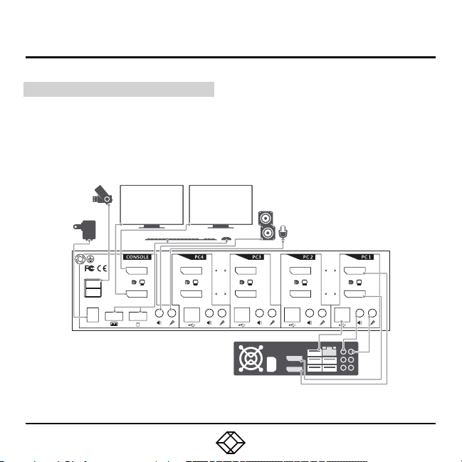
STEP 2 - Connection Diagram
EXAMPLE CONNECTION DIAGRAM
The dia gram illust rated here is an example
of KV62 24A. The ac tual applic ation may var y.
All ill ustrated co mputer, acce ssories and
monitors are no t included in t he package;
they are for reference only.
DC 9V
HUB
B
A
B
A
B
A
Page 5

STEP 3 - Installation Steps
STEP-BY-STEP INSTALLATION
1. Power up your KVM switch by connecting
the external power adapter to it.
2. Connect the shared USB keyboard, mouse,
two DisplayPort monitors, speaker/headphone
and microphone to the corresponding console
ports in the console sec tion of the switc h.
NOTE: The lower t wo USB ports are for keyboard
and mouse.
3. Conn ect each KVM PC port to compute rs,
using t wo or four DisplayPort cables (male to
male), on e USB cab le (Type A to Type B) and one
audio and microphone co mbo cable (male to
male).
4. Connect your USB hub to the USB hu b port
on the left.
HUB
DC 9V
Keyboard
B
Mouse
B B
A
A
Page 6

STEP 4A - Front-Panel Pushbuttons
FRONT-PANEL PUSHBUTTONS
Front- panel buttons allow you to direc tly
control the KVM switching operation. Simply
press the button to toggle to the selected PC
port (together with hub port control and/or
audio/mic port, if binding is enabled).
By default, PC port swi tching , hub port control
and audio/ mic por t switching are bound
together, unless you specify the audio to be
fixed to a s pecific port.
TABLE 2. FRONT-PANEL PUSHBUTTONS FUNCTIONS
COMMAND PUSHBUTTON DESCRIPTION
Select PC por t
Select Hub
Port control
Defin e Hotkey
Preceding
Sequence
Press the c orresponding button to
select the active PC port
Press the b utton to toggle the specific
PC + USB hub port control. (It works
only if PC port/ hub port control
binding is enabled.)
Press and h old down the last button
(Button 2/Button 4) until yo u hear two
beeps, release the button,
then press the (y) key.
Selec t the active PC por t. (Jointly sele ct PC port/
hub por t control/audio mic, if binding is enable d.)
Selec t the PC port that controls all USB hub ports.
(Jointly select PC & hub port co ntrol, if PC/hub port
control binding is en abled.)
Selec t the hotkey preced ing sequence am ong
5 alternative keys.
Page 7

STEP 4B - Keyboard Hotkeys
KEYBOARD HOTKEYS
Front- panel A keyboard hotkey sequence
consists of at least three s pecific keystrokes.
See the Quick Reference Guide in S tep 4C.
Hotkey sequenc e = [ScrLk]* + [ScrLk] * +
Command key(s)
* User- definable = SCROL L LOCK, CAPS, ESC,
F12 or NUM LO CK
Hotkey preceding sequence configuration: For
users w ho want to use a preceding sequence
other than two co nsecutive Scroll Locks , there
is also on e convenient way to configure it.
1. Press Sc rollLock + ScrollLock + H, then two
beeps will signal readiness for new p receding
seque nce selecti on [or Press and hold down
the last front- panel button (Button 2 or But ton
4) until you hear two beeps, then release the
button.]
2. Select and press the key you would li ke to use
as your preceding seque nce (SCROLL LOCK,
CAPS , ESC, F12 or NUM LO CK keys are available
for selection) and you’ll hear a beep for selec tion
confirmation. Now you can use the new preceding
seque nce to execute your hotkey command s.
NOTE: Each keys troke within a hotkey sequence
should be pressed within 2 second s. Otherwise,
the hotkey sequence will not be validated.
Page 8

STEP 4C - Keyboard Hotkeys Quick Reference
TABLE 3. HOTKEY COMMANDS
COMMAND HOTKEY SEQUENCE DESCRIPTION
Select PC por t
Select Hub
Port control
Defin e Hotkey
Preceding
Sequence
Select Audio &
Mic Control
Bind PC and Hub
Port C ontrol
Switching
Unbind PC and
Hub Por t Control
Switching
Bind PC and
Audio & Mic
Switching
ScrLk + ScrLk + (x)
x = 1–2/1–4 for PC por t number
ScrLk + ScrLk + (Fx)
Fx = 1–2/1–4 for hub por t number
ScrLk + ScrLk + H + ( y)
y = SCROL L LOCK, CAPS, ESC, F12, or
NUM LOCK
ScrLk + ScrLk + (Fy)
Fy = F5–F6/F5–F8 (Fy is a function key)
y = 5–6/5–8 fo r audio & mic port number
ScrLk + ScrLk + Z
ScrLk + ScrLk + X
ScrLk + ScrLk + Q
Selec t the active PC por t. (Jointly sele ct PC
port /hub port co ntrol/audio mic, if binding
is enabled.)
Selec t the PC port that controls all USB hub
ports. (Jointly se lect PC & hub por t control,
if PC/hu b port control b inding is enabled.)
Selec t the hotkey preced ing sequence
among 5 alternative keys.
Selec t the active audio & mi c port (Jointly
select PC & audio & mic p ort, if binding
is enabled.)
Enable the binding of P C port and hub po rt
control switching. (Once this feature is
enable d, any PC and/or hub po rt control
switchin g is bound together. Factory default.)
Disable t he binding of PC port and hub port
control switching.
Enable the binding of P C port and audio & mic
switchin g. (Once this feature is enabled , any
PC and/or audio & mic switching is bound
together. Factory default.)
Page 9

STEP 4C - Keyboard Hotkeys Quick Reference
TABLE 3 (CONTINUED). HOTKEY COMMANDS
COMMAND HOTKEY SEQUENCE DESCRIPTION
Unbind PC and
Audio & Mic
Switching
Previous PC port ScrLk + ScrLk + ar row up
Next P C port ScrLk + Scr Lk + arrow down
Previous/Current
PC port
Beep Sound
On/Off
Autoscan ScrLk + ScrLk + S
Autosc an with
Programmable
Delay Time
Stop Autoscan Press any button Terminate Autoscan activity
ScrLk + ScrLk + W
ScrLk + ScrLk + backspace
ScrLk + ScrLk + B Toggle on/off the beep sound while autoscanning.
ScrLk + ScrLk + S + (z)
z = 0–9
1 10", 2 20", 3 30 ", 4 40", 5 50", 6 60",
7 70", 8 80", 9 9 0" 10 100"
Disable t he binding of PC port and audi o & mic
switching
Selec t the previous con nected PC por t. (Jointly
select PC/hub port control, if binding is enable d.)
Selec t the next conne cted PC port.
(Jointly select PC/ hub port control, if binding
is enabled.)
Toggle between the previous por t and
current port.
Autoscan through eve ry connected port
for quick screen browsing of each po rt
(scan delay = 5 sec.)
Autoscan with a user- defined delay time
within a range of 10–100 seconds
Page 10

STEP 4D - Hotkey Commands Notes
NOTES
1. The USB ke yboard h otkeys all ow you a faster
and broader con trol for your K VM switc hing
operation in addition to the front-panel button.
If you have c onfigured a hotkey prece ding
seque nce other than two consecutive scroll
locks , here you should ch ange your hotkey
seque nce accordi ngly. (For preceding sequ ence
key conf iguration, refer to the Sw itching
Commands table.)
2. When the binding of PC & US B hub port
control switching is enabled by th e hotkey
seque nce: ScrLk + S crLk + Z, any PC and hub
port control switching are bou nd together.
To remove this binding , use the hotkey
seque nce: ScrLk + S crLk + X.
3. When t he binding of PC and audio & mic
switching is ena bled by th e hotkey sequence:
ScrL k + ScrLk + Q, any PC and audio & mic
switching are bound toge ther. To remove this
binding, use the hotkey sequence:
ScrL k + ScrLk + W.
Page 11

STEP 5 - Download User Manual (Optional)
OPTIONAL: DOWNLOAD USER MANUAL
For product specific ations and regulatory
information, refer to the U ser Manu al. You can
download this document from our we b site.
1. Go to www.blac kbox.com
2. Ente r the part num ber (KV622 2A or KV6224A)
in the search box.
3. Click on the product in th e “Product Results”
page.
4. Click on the “Support” tab on the product pag e,
and sel ect the docu ment you wish
to download.
Page 12

STEP X - Name of Step
COPYRIGHT 2017 BLACK BOX CORPORATION. ALL RIGHTS RESERVED.
 Loading...