

DP CyberSerial Quick Installation Manual

DP CyberSerial PCIe
Quick Installation Guide
Introducing the DP CyberSerial PCIe
The DP CyberSerial PCIe high-speed serial I/O card
provides one additional 9-pin serial port.
Features and Benefits
• Compliant with PCI Express Base Specification,
Revision 1.1
• PCI Express 1-lane (x1) serial I/O card works with
PCI Express slots with different lane width
• Spare enhanced low profile bracket is included to
work in low profile chassis
• Built-in 128-byte FIFO buffers dramatically increase
data transmit/receive speed, especially under
Windows multitasking environment
• Works as standard RS232 port or with 5V or 12V
power output for devices that require power
System Requirements
• PCI Express-enabled system with an available PCI
Express slot
• Windows® 8 (32-/64-bit) / 7 (32-/64-bit) / Vista (32-
/64-bit) / XP (32-/64-bit) / Server 2003 & 2008 (32/64-bit) / Server 2008 R2 / 2000
Package Contents
• DP CyberSerial PCIe
• Spare low profile bracket & "Y" split power cable
• Driver CD & quick installation guide
04-0564C
1
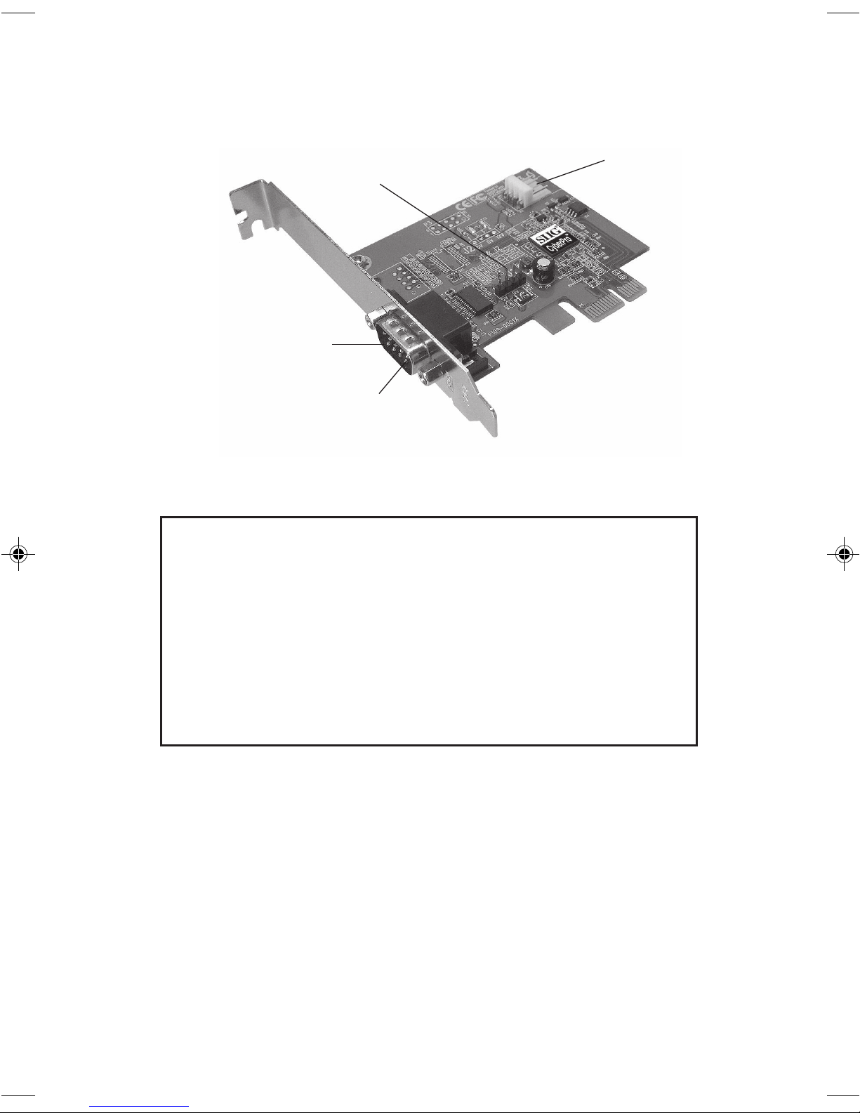
Layout
Jumper (J1)
Serial Port
(9-pin)
Pin 9
Figure 1: DP CyberSerial PCIe Layout
Power
Connector*
* Note: If the serial port requires power output,
connect the system power source to board's power
connector. However, most serial devices do not
require additional power through the serial port.
Refer to your serial device's manual for more
information. Included is a "Y" split power adapter
cable, to use in case your power source doesn't have
the proper power connection.
Jumper Settings (J1)
Power output is from Pin 9 on the 9-pin serial port.
Short 2-3 or no jumper = 0 volts
Short 1-2 = 5V
Short 3-4 = 12V
2

Hardware Installation
General instructions for installing the card are provided
below. Since the design of computer cases and
motherboards vary, refer to your computer's reference
manual for further information, if needed.
Static Electricity Discharge may permanently damage
your system. Discharge any static electricity build up in
your body by touching your computer case for a few
seconds. Avoid any contact with internal parts and handle
cards only by their external edges. Note: For low profile
systems, replace the currently mounted bracket with the included
low profile bracket.
1. Turn OFF the power to your computer and any
other connected peripheral devices.
2. Unplug the power cord and remove the computer
cover.
3. Remove the slot bracket from an available PCIe slot.
4. Set jumper setting to the desired voltage only if
your serial device needs additional power from the
serial port. However, most serial devices do not
require additional power. See Layout and Jumper
Settings on page 2 for more details. If power output
is required, connect the board's power connector to
the system power source. Skip this step if power from
the serial port is not needed.
5. To install the card, carefully align the card's bus
connector with the selected PCIe slot on the
motherboard. Push the board down firmly, but
gently, until it is well seated.
6. Secure the card with the slot bracket holding screw.
7. Replace the computer cover and reconnect the power
cord.
3
 Loading...