

Page 1
ÉQUIPEMENT DOYON INC.
1255, rue Principale
Linière, Qc, Canada G0M 1J0
Tel.: 1 (418) 685-3431
Canada: 1 (800) 463-1636
US: 1 (800) 463-4273
FAX: 1 (418) 685-3948
Internet: http://www.doyon.qc.ca
e-mail: doyon@doyon.qc.ca
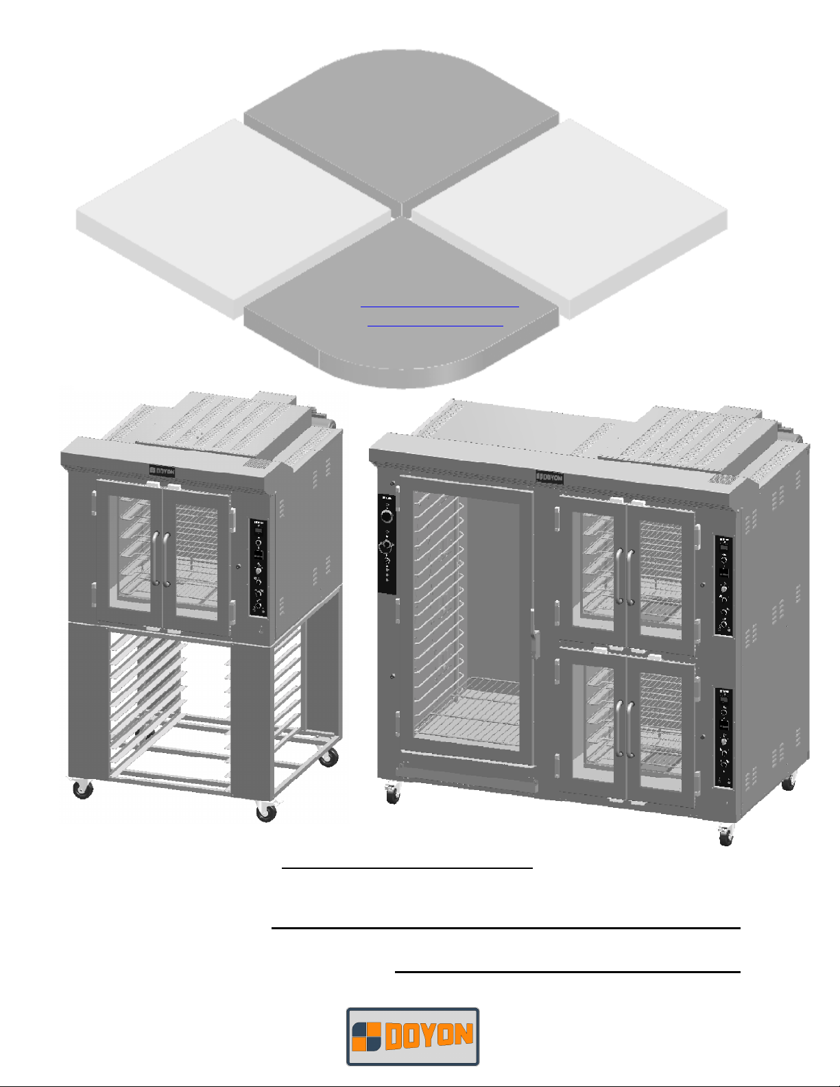
CA6-CAOP6 - CA12-CAOP12
Product / Produit:
Serial number / Numéro de série:
Page 2

IMPORTANT SAFETY INSTRUCTIONS
SAVE THESE INSTRUCTIONS
DANGER
TO REDUCE THE RISK OF FIRE OR ELECTRIC SHOCK
CAREFULLY FOLLOW THESE INSTRUCTIONS
TABLE OF CONTENTS
(table des matières :page suivante)
DESCRIPTION________________________________________________________________ A-1
Introduction________________________________________________________________ A-1
Construction _______________________________________________________________ A-1
Shipping __________________________________________________________________ A-1
Installation warnings_________________________________________________________ A-3
Distances to respect__________________________________________________________ A-3
Installation ________________________________________________________________ A-5
Bearing maintenance_________________________________________________________ A-5
Operation of the oven ________________________________________________________ A-7
Instructions for oven _________________________________________________________ A-8
Operation of the proofer _____________________________________________________ A-11
Power failure______________________________________________________________ A-11
ECM-1 Programmable control - Operating modes_________________________________ A-13
Manual mode _____________________________________________________________ A-15
Program mode_____________________________________________________________ A-16
ECM-2 Programmable control - Operating modes_________________________________ A-27
Troubleshooting ___________________________________________________________ A-29
Oven maintenance and cleaning _______________________________________________ A-33
Bake chart ________________________________________________________________ A-35
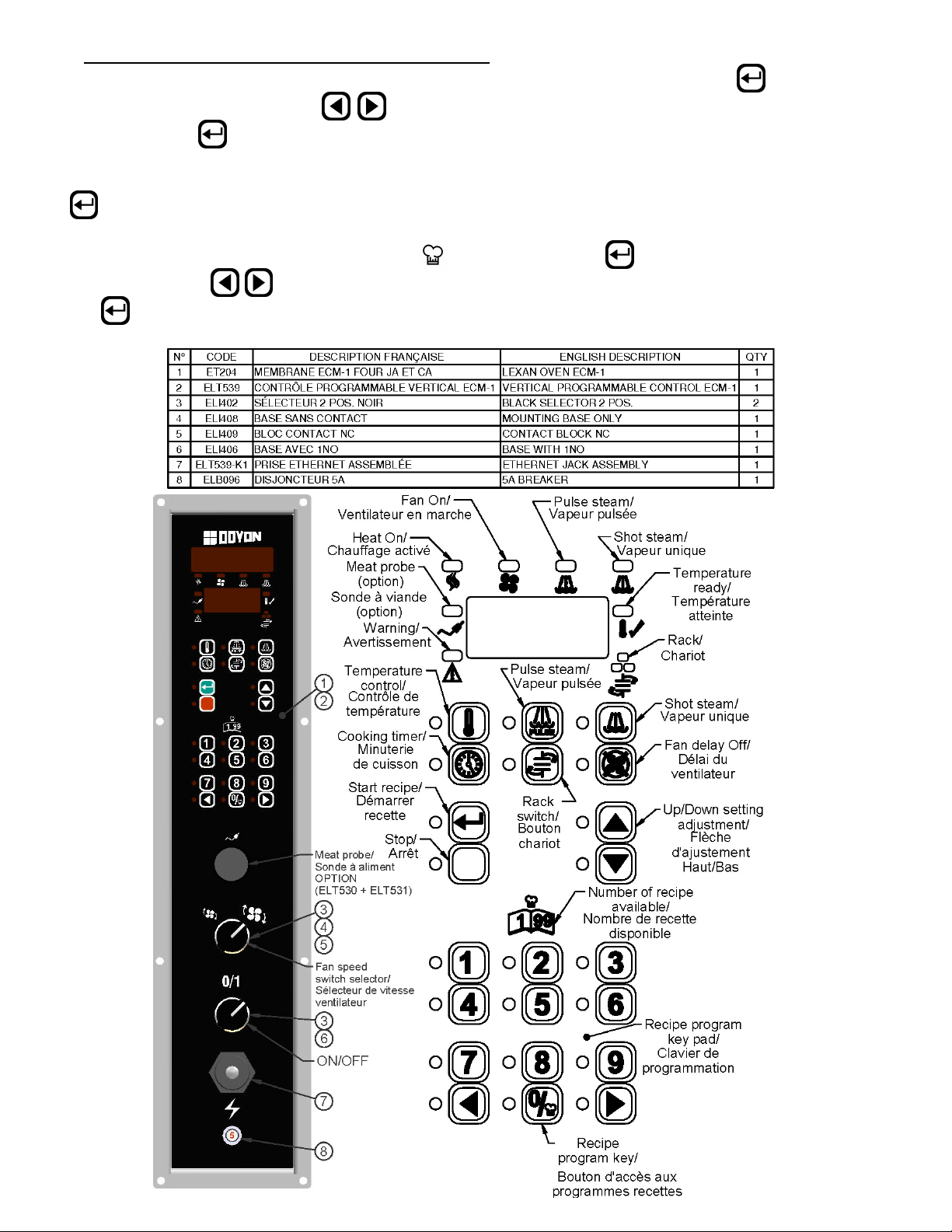
COMPONENT PARTS __________________________________________________________B-1
CA12 – Front view ___________________________________________________________B-1
CA12 – Back left view ________________________________________________________B-3
CAOP6 – Front view _________________________________________________________B-5
CAOP6 - Back left view _______________________________________________________B-7
CAOP12 – Front view ________________________________________________________B-9
CAOP12 – Back right view ___________________________________________________B-11
Rotatif rack system __________________________________________________________B-13
Element ___________________________________________________________________B-14
CONTROL PANELS ____________________________________________________________C-1
Standard Electric box for CA6 & CAOP6 _________________________________________C-1
Electric box ECM-1 for CA6 & CAOP6 __________________________________________C-2
Standard Electric box for CA12 & CAOP12 _______________________________________C-3
Electric box ECM-1 for CA12 & CAOP12 ________________________________________C-4
FAM CA [LIVRET].doc 04/10
Page 3

IMPORTANT INSTRUCTIONS DE SÉCURITÉ
CONSERVEZ CE MANUEL D’INSTRUCTIONS
DANGER
AFIN DE RÉDUIRE LES RISQUES D'INCENDIE OU D'ÉLECTROCUTION
SUIVRE CES INSTRUCTIONS AVEC SOIN
TABLE DES MATIÈRES
DESCRIPTION _________________________________________________________________A-2
Introduction ________________________________________________________________A-2
Construction ________________________________________________________________A-2
Expédition __________________________________________________________________A-2
Avertissement lors de l'installation_______________________________________________A-4
Distances à respecter _________________________________________________________A-4
Installation _________________________________________________________________A-6
Entretien du roulement à rouleaux coniques _______________________________________A-6
Opération du four ____________________________________________________________A-9
Instructions pour four ________________________________________________________A-10
Opération de l'étuve _________________________________________________________A-12
Panne de courant ___________________________________________________________A-12
Contrôle programmable ECM-1 - Modes d'opération _______________________________A-20
Mode manuel_______________________________________________________________A-22
Mode programmable_________________________________________________________A-23
Contrôle programmable ECM-2 - Modes d'opération _______________________________A-28
Dépannage ________________________________________________________________A-31
Entretien et nettoyage du four__________________________________________________A-34
Tableau de cuisson __________________________________________________________A-36
PIÈCES COMPOSANTE _________________________________________________________B-1
CA12 – Vue de face___________________________________________________________B-1
CA12 – Vue arrière gauche ____________________________________________________B-3
CAOP6 – Vue de face _________________________________________________________B-5
CAOP6 – Vue arrière gauche___________________________________________________B-7
CAOP12 – Vue de face ________________________________________________________B-9
CAOP12 – Vue arrière droite__________________________________________________B-11
Système de rotation chariot ___________________________________________________B-13
Element ___________________________________________________________________B-14
PANNEAUX DE CONTRÔLE _____________________________________________________C-1
Boîte électrique Standard pour CA6 et CAOP6 _____________________________________C-1
Boîte électrique ECM-1 pour CA6 et CAOP6 ______________________________________C-2
Boîte électrique Standard pour CA12 & CAOP12 ___________________________________C-3
Boîte électrique ECM-1 pour CA12 & CAOP12 ____________________________________C-4
FAM CA [LIVRET].doc 04/10
Page 4

A-1
SECTION A:
DESCRIPTION
INTRODUCTION
The manufacturer suggests to read this manual carefully.
This equipment is manufactured with first quality material by experienced technicians. Proper installation
and maintenance will guarantee a reliable service for years to come.
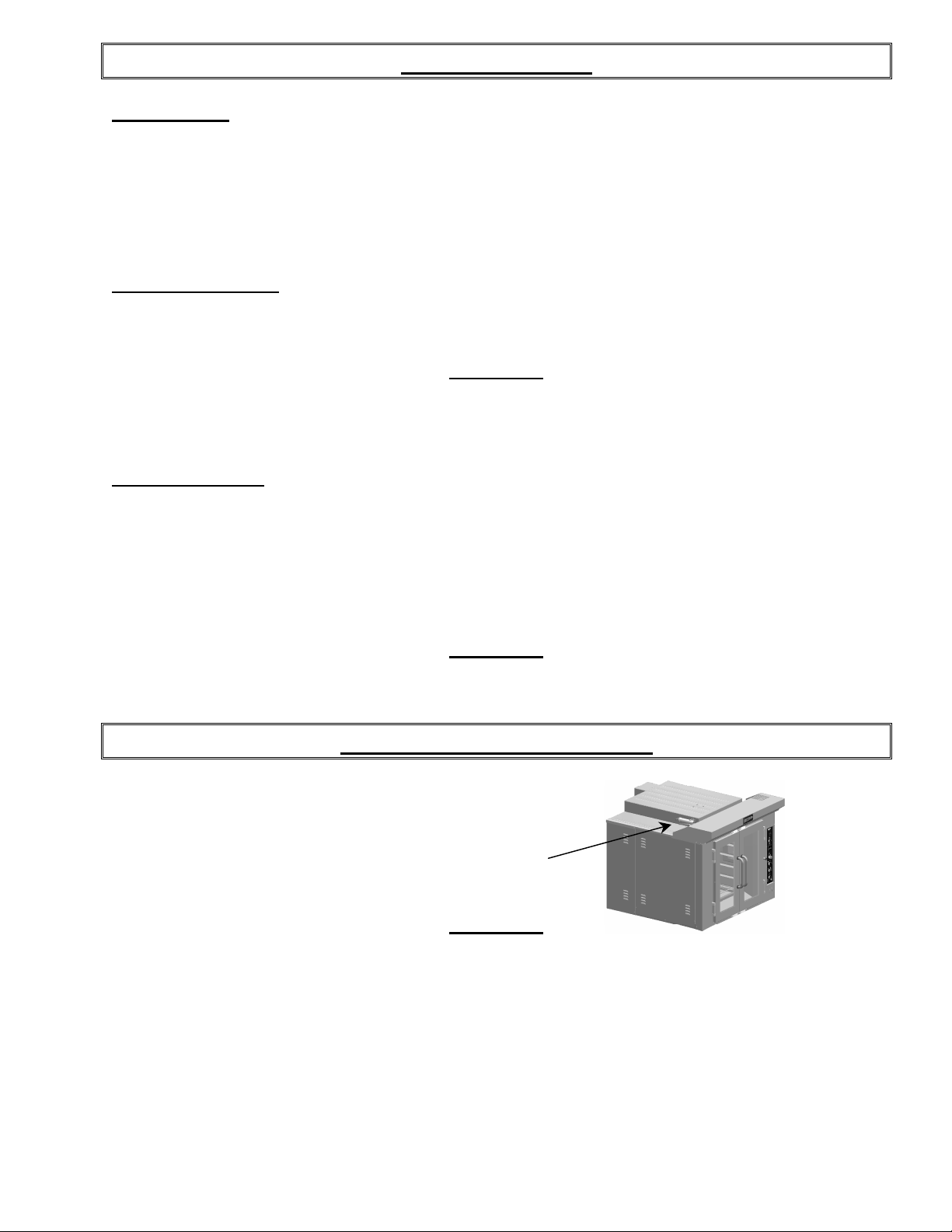
A nameplate fixed to the front or right side of the oven specifies the model number, serial number,
voltage and amperage.
Drawings and replacement parts numbers are included in this manual. The electrical diagram is affixed in
the control panel at the back of the oven.
ATTENTION
DOYON is not responsible for damages to the property or the equipment caused
by personnel who is not certified by known organisations. The customer is
responsible for finding qualified technicians in electricity and plumbing for the
installation of the oven.
CONSTRUCTION
You just bought the most advanced oven in the world, "DOYON" technology at its best. This oven is
manufactured using the highest quality components and material.
The oven gives a perfect uniform baking with its unique Circle Air convection system. The DOYON
oven is designed with parts that are easy to find.
SHIPPING
For your safety, this equipment has been verified by qualified technicians and carefully crated before
shipment. The freight company assumes full responsibility concerning the delivery in good condition of
the equipment in accepting to transport it.
IMPORTANT
RECEPTION OF THE MERCHANDISE
Take care to verify that the received equipment is not damaged before signing the delivery receipt. If a
damage or a lost part is noticed, write it clearly on the receipt. If it is noticed after the carrier has left,
contact immediately the freight company in order that they do their inspection.
We do not assume the responsibility for damages or losses that may occur during transportation.
Page 5

A-2
DESCRIPTION
INTRODUCTION
Le fabricant suggère de lire attentivement ce manuel et de suivre avec soin les instructions fournies.
Votre équipement est fabriqué avec des matériaux de première qualité par des techniciens
d'expérience. Une utilisation normale et un entretien adéquat de l'équipement vous assureront
plusieurs années de bon service.
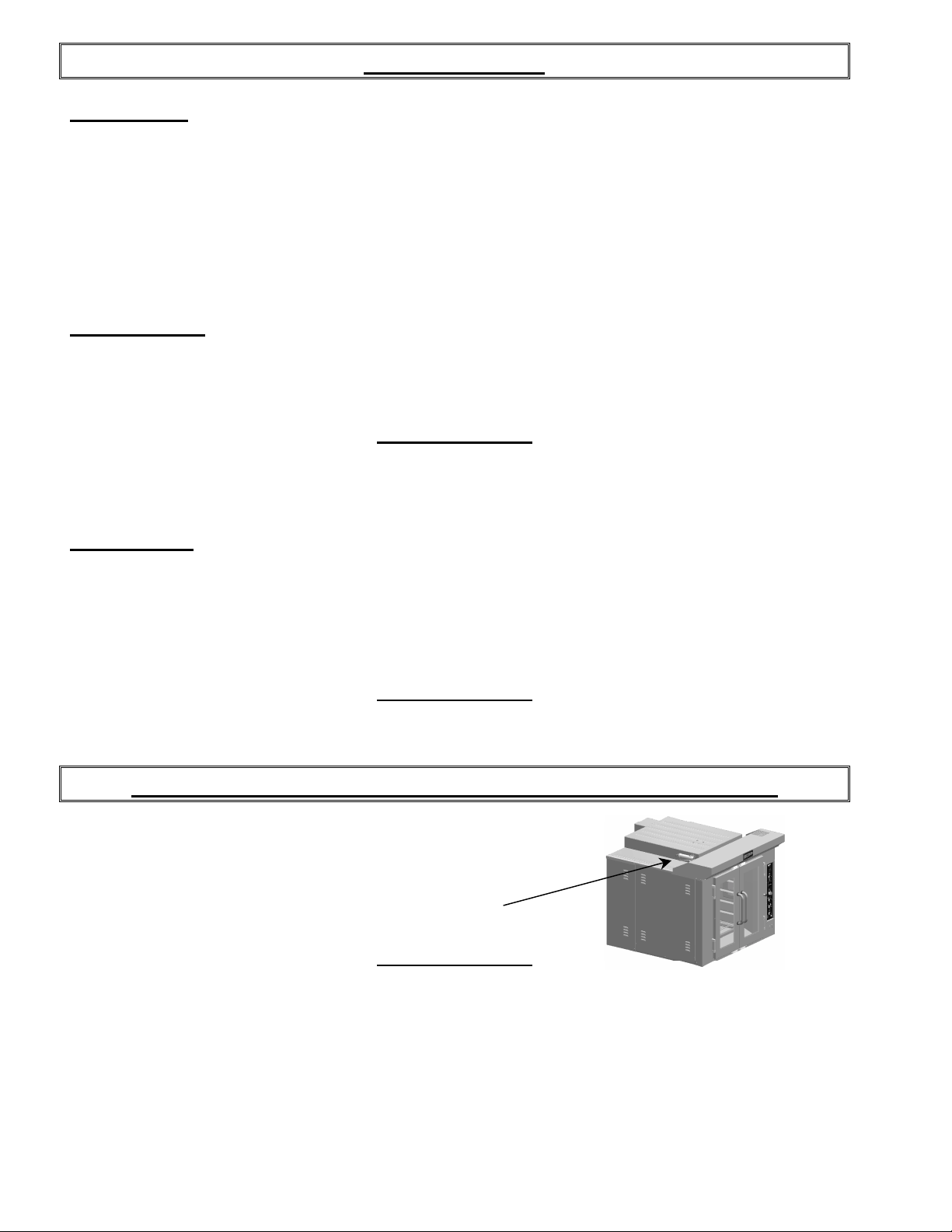
Une plaque signalétique, située sur le coin avant droit ou le côté droit du four, mentionne le numéro
de modèle, le numéro de série, la tension et l'ampérage.
Les dessins et les numéros de pièces de rechange sont inclus dans ce manuel. Le plan électrique est
affiché dans la boîte de contrôle à l'arrière du four.
ATTENTION
Équipement Doyon Inc. ne peut être tenu responsable pour les dommages causés à la
propriété ou à l'équipement par du personnel non certifié par des organismes
accrédités. Le client a la responsabilité de retenir les services d'un technicien
spécialisé en électricité et d'un plombier qualifié pour l'installation du four.
CONSTRUCTION
Vous avez maintenant en votre possession le four le plus performant présentement disponible sur le
marché, un four utilisant la technologie "DOYON" à son meilleur. Ce four est fabriqué avec des
matériaux de première qualité.
Avec son système unique de convection "Circle Air", ce four vous permettra d'obtenir une cuisson
uniforme. Le four Doyon est fabriqué avec des matériaux et pièces composantes facilement disponibles
sur le marché.
EXPÉDITION
Pour votre protection, cet équipement a été vérifié et emballé avec précaution par des techniciens
qualifiés avant son expédition. La compagnie de transport assume la pleine responsabilité concernant
la livraison de cet équipement en bon état en acceptant de le transporter.
IMPORTANT
RÉCEPTION DE LA MARCHANDISE
Avant de signer le reçu de livraison, prenez soin de vérifier dès la réception si l'équipement n'est pas
endommagé. Si un dommage ou une perte est détecté, écrivez-le clairement sur le reçu de livraison ou
votre bon de transport et faites signer le livreur. Si le dommage est remarqué après le départ du
transporteur, contactez immédiatement la compagnie de transport afin de leur permettre de constater
les dommages causés.
Nous ne pouvons assumer la responsabilité pour les dommages ou les pertes qui pourraient survenir
pendant le transport.
Page 6

A-3
INSTALLATION WARNINGS
POWER FAILURE WARNING
WHEN YOU HAVE A POWER FAILURE, SHUT OFF THE OVEN POWER SWITCH TO
PROTECT THE ELECTRONIC COMPONENTS WHEN THE POWER COMES BACK.
FOR YOUR SAFETY
DO NOT STORE OR USE GASOLINE OR OTHER FLAMMABLE VAPORS
AND LIQUIDS IN THE VICINITY OF THIS OR ANY APPLIANCE.
INSTALLATION AND SERVICE
WARNING
IMPROPER INSTALLATION, ADJUSTMENT, ALTERATION, SERVICE OR
MAINTENANCE CAN CAUSE PROPERTY DAMAGE, INJURY OR DEATH.
READ THE INSTALLATION, OPERATING AND MAINTENANCE INSTRUCTIONS
THOROUGHLY BEFORE INSTALLING OR SERVICING THIS EQUIPMENT.
Installation and service must be done by specialised technicians. Contact a certified electrician and
plumber for set up.
The oven must be connected to the utility and electrically grounded in conformity to the effective local
regulations. If these are not established, the oven must be connected according to the Canadian
Electrical Code (CSA-C22.1-XX) or National Electrical Code (NFPA 70-XX). Refer to last edition
year for XX. Installation must also allow proper access for service (24 inches each side and back).
The ovens must be installed with a proper ventilation according with the local building code.
DISTANCES TO RESPECT
A) Back and sides of the oven: 1 inch.
B) Top of the oven: a clearance of 12 inches to the ceiling must exist to permit adequate venting.
C) Floor: 4 inches minimum.
D) Sides of the oven: do not install other than easily removable equipment for service and
maintenance (not closer than 1 inch).
E) It is recommended to have a certain length of water pipe, electric cable between oven and wall
to help gain access for service.
Page 7

A-4
AVERTISSEMENT LORS DE L'INSTALLATION
PANNE ÉLECTRIQUE
LORS D'UNE PANNE ÉLECTRIQUE, FERMER L'INTERRUPTEUR DU FOUR POUR
PROTÉGER LES COMPOSANTES ÉLECTRONIQUES.
POUR VOTRE SÉCURITÉ
NE PAS EMMAGASINER OU UTILISER D'ESSENCE OU AUTRES VAPEURS
ET LIQUIDES INFLAMMABLES À PROXIMITÉ DE CET ÉQUIPEMENT
OU DE TOUT AUTRE APPAREIL.
INSTALLATION ET SERVICE
AVERTISSEMENT
UNE INSTALLATION, UN AJUSTEMENT, UNE ALTÉRATION, UN SERVICE OU UN
ENTRETIEN NON CONFORME AUX NORMES PEUT CAUSER DES DOMMAGES À LA
PROPRIÉTÉ, DES BLESSURES OU LA MORT. LIRE ATTENTIVEMENT LES DIRECTIVES
D'INSTALLATION, D'OPÉRATION ET D'ENTRETIEN AVANT DE FAIRE L'INSTALLATION
OU L'ENTRETIEN DE L'ÉQUIPEMENT.
L'installation et le service doivent être faits par un technicien spécialisé. Contactez un technicien
spécialisé en électricité.
Cet appareil doit être branché et mis à la terre (grounded) conformément aux règlements effectifs de
votre localité. Si aucune réglementation n'est établie, le four doit être branché conformément au Code
Canadien de l’électricité CSA 22.1-XX ou au Code National de l'Électricité NFPA 70-XX. Référez-vous à
l’année de la dernière édition pour XX. L'installation doit aussi permettre un accès suffisant pour
effectuer le service sur l'équipement (24 pouces sur toutes les faces).
Le four doit être installé sous une ventilation adéquate respectant les norme locales.
DISTANCES À RESPECTER
A) Arrière et côtés du four : 1 pouce.
B) Dessus du four : Il est obligatoire d'avoir au moins 12 pouces entre le dessus du four et le
plafond de manière à permettre une ventilation adéquate.
C) Plancher : Une distance de 4 pouces minimum.
D) Les côtés du four : Installer uniquement des équipements légers et faciles à déplacer pour être en
mesure d'effectuer l'entretien de l'appareil (1 pouce minimum).
E) Il est recommandé d'installer une longueur supplémentaire de tuyau d'eau, de câble électrique
entre le four et le mur pour faciliter l'accès au technicien.
Page 8
A-5
INSTALLATION
IN GENERAL
Take off the packaging material with care. Take off all the material used for packing and accessories.
If the equipment is delivered with casters, always lock them after installation and use flexible wire. It
must also be installed with restraining device (chain comes with the oven) to guard against
transmission of strain to the gas supply and connectors.
1. To the electrician
Electrical supply installation must be in accordance with the electrical rating on the nameplate.
WARNING
The electrician must make sure that the supply cable does not come in contact
with the oven top which becomes hot.
2. To the plumber
This equipment is to be installed to comply with the applicable federal, state or local plumbing codes.
Connect the steam system (1/4 NPT) to the cold water distribution network.
We highly recommend to use a water softener to eliminate minerals in the water.
We suggest you to use CUNO # CFS6135 (Doyon part number PLF240).
WARNING
Do not adjust the needle valves, it has been done at the factory.
BEARING MAINTENANCE
Every month you must grease the bearing situated at the
bottom of the oven. To lubricate the oven you need to
use the zerk located in the front bottom for the simple
oven and at the center for the double oven .
Use the grease gun located on top of the oven. Only two
squeezes will be sufficient.
WARNING
It is very important to use the same type of grease that the manufacture recommends.
High temperature grease DUPONT GPL227FG
Otherwise the warranty of the unit will be annulled.
Page 9
A-6
INSTALLATION
EN GÉNÉRAL
Ouvrir avec soin l'emballage de votre équipement. Enlever tous les matériaux utilisés pour
l'envelopper ainsi que les accessoires.
Si l'appareil est muni de roulettes, veuillez toujours les bloquer après l'installation et utiliser un
cordon flexible. De plus, des équipements de retenues (chaîne comprise avec le four) doivent être
installés pour empêcher le tuyau d'alimentation et les connecteurs de subir des tensions lorsque le four
est déplacé.
1. À l'électricien
L'installation de l'alimentation électrique des fours doit être conforme avec la source électrique
spécifiée sur la plaque signalétique de l’appareil.
AVERTISSEMENT
L'électricien doit s'assurer que le câble d'alimentation ne touche pas le dessus du
four à cause du degré élevé de chaleur dégagée par celui-ci.
2. Au plombier
Relier le système de vapeur (1/4 NPT) au réseau de distribution d'eau froide.
Il est fortement recommandé d'installer un adoucisseur d’eau à l’entrée de l’appareil afin d’éliminer
les minéraux dans l’eau.
Nous recommandons la marque CUNO # CFS6135 (numéro de pièce DOYON PLF240).
AVERTISSEMENT
Ne jamais changer l'ajustement des valves à aiguille pré-ajustées.
ENTRETIEN DU ROULEMENT À ROULEAUX CONIQUES
À tous les mois, vous devez graisser le roulement à
rouleaux coniques situé dans le bas du four. Celui-ci se
graisse à l’avant du four par le graisseur situé en bas
(four simple) ou au centre du four (four double).
Utiliser le pistolet graisseur situé sur le dessus du four.
Deux coups de poignée du graisseur suffisent.
AVERTISSEMENT
Il est important d’utiliser le même type de graisse que suggéré par le fabricant, sinon la garantie de
l’appareil sera annulée.
Graisse haute température DUPONT GPL227FG
Page 10
A-7
OPERATION OF THE OVEN
1. Turn the switch to the "1" position.
• The light inside the oven must light up.
2. Adjust the thermostat at the desired setting (see THERMOSTAT INSTRUCTIONS below).
N.B. The red light must be "ON" (If not, press the breaker on the front).
3. Heat the unit until you reach the baking temperature.
When the desired temperature is reached, the red light goes out and turns green.
If the light is still "ON" and the oven does not produce heat, call for service.
4. Load the oven as fast as possible to avoid letting out too much heat.
5. Set the timer to the desired value and start it. (See page A-8.)
NOTE: The timer does not shut the oven off at the end of its cycle. It simply activates the
buzzer.
6. Wait until the product is ready. Do not open the doors until the product is done.
VERY IMPORTANT
This oven has an overheat warning alarm to protect the electrical components against overheating. If
the red pilot light (OVERHEAT WARNING) is lit and you hear a buzzer, see Troubleshooting.
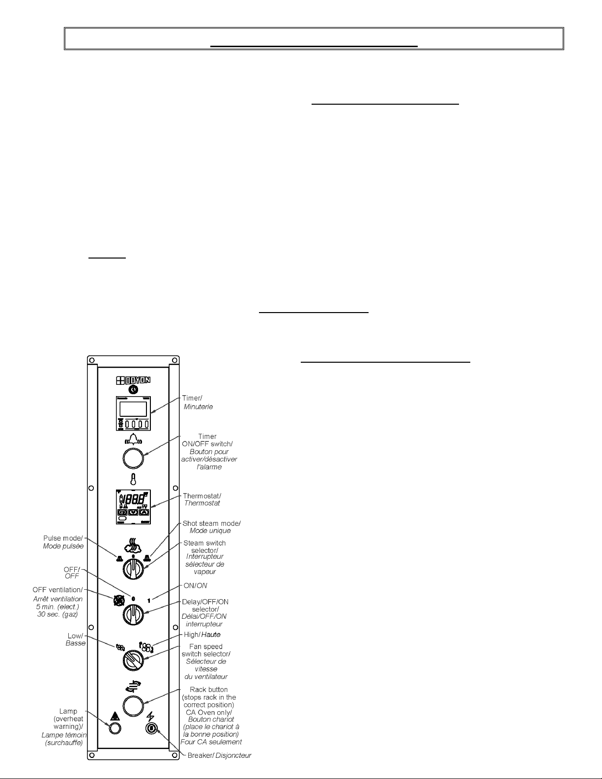
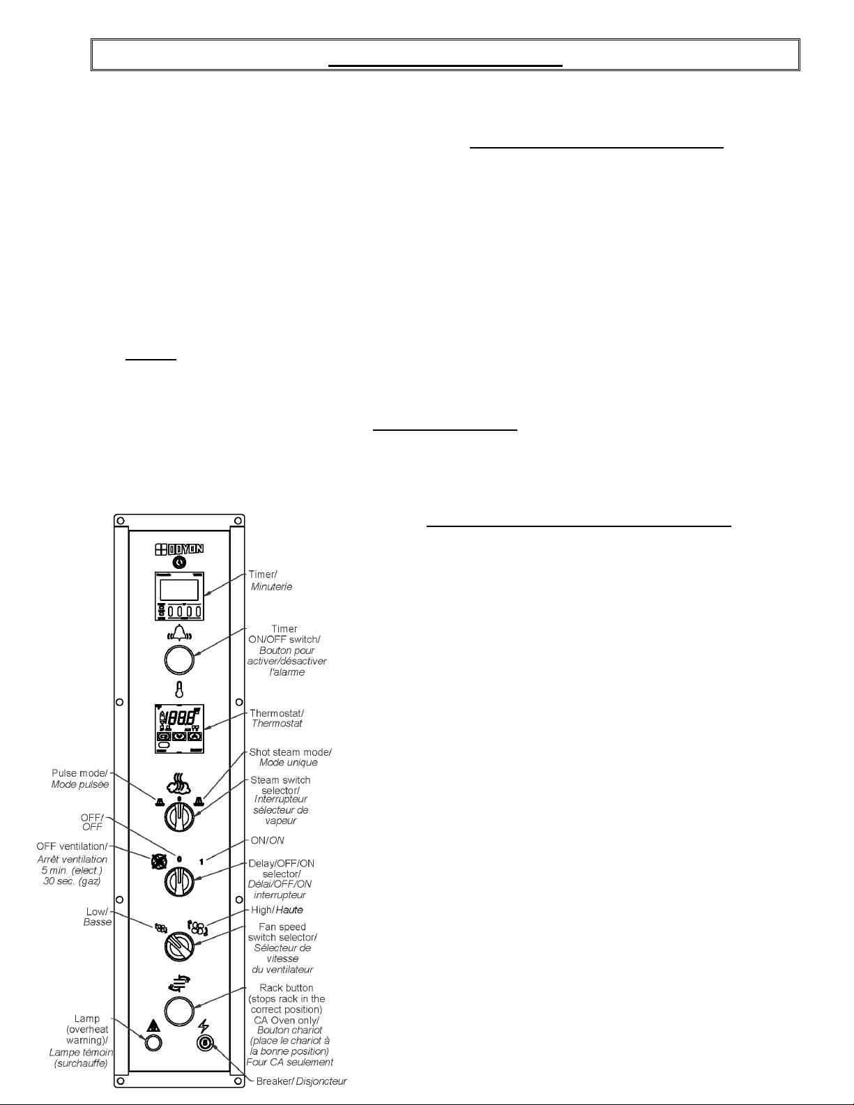
THERMOSTAT INSTRUCTIONS
To obtain a very good thermal stability, we use a
digitaltemperature controller with thermocouple. The Omron
E5CS thermostat controls the heat of every element at the SP (set
point).
The temperature of the oven is always shown on the display of
the thermostat and an arrow indicates if the temperature is over
or below the SP. When the green light is lit, it indicates that the
temperature is at the SP ± 1 %.
To adjust the SP (set point) value, you just have to press the key
on the left and use the up and down keys to set the temperature.
Press the left key to return to run mode.
Page 11
A-8
INSTRUCTIONS FOR OVEN
OPENING AND CLOSING THE DOORS
To open the doors: Open one of the doors up to 2" and wait 2 seconds to let the fan reduce its
spinning before opening them completely.
To close the doors: Close the first door completely and the second door down to 2" and wait 2
seconds before closing completely and then hold the door closed for 2 seconds.
P.S. Open the doors as little as possible. This will affect the baking.
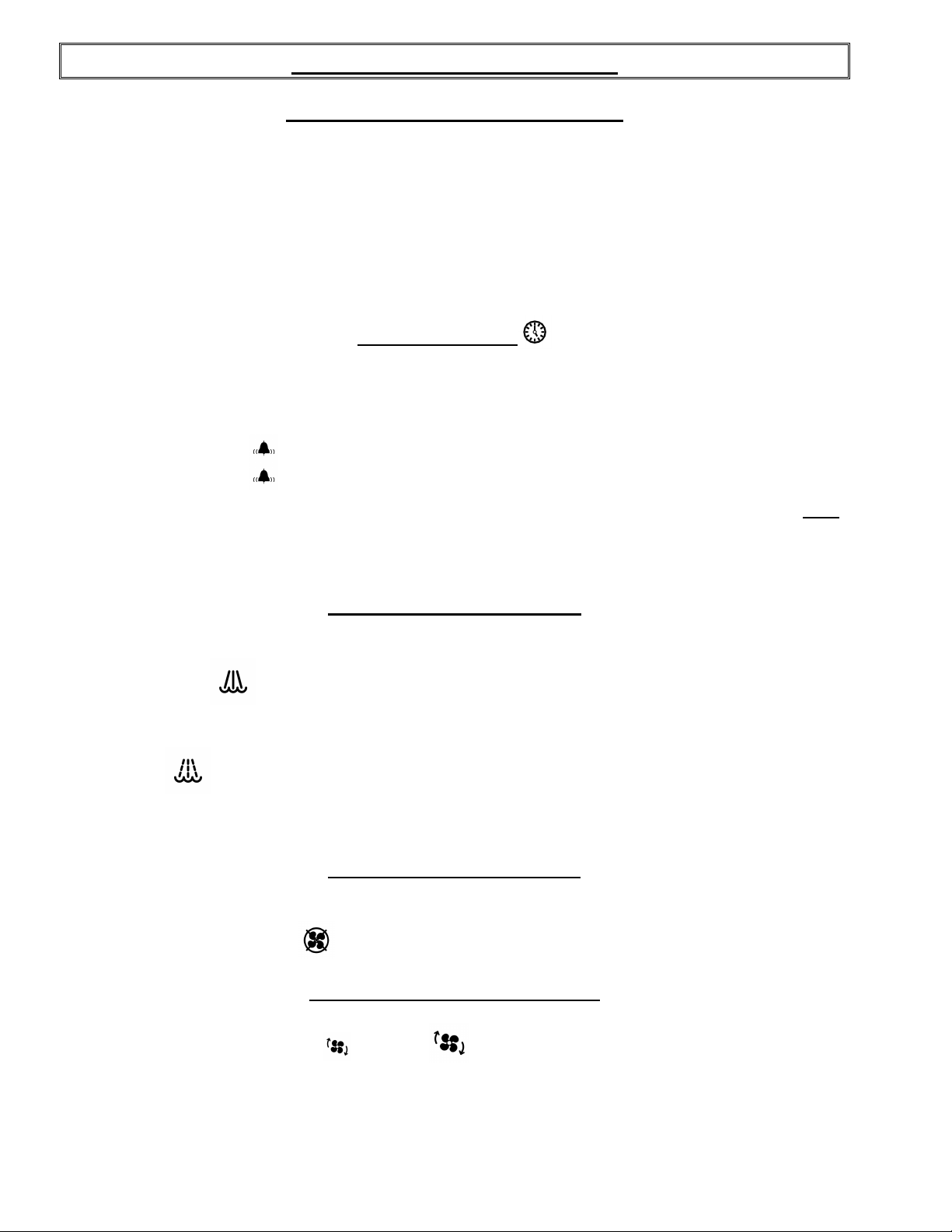
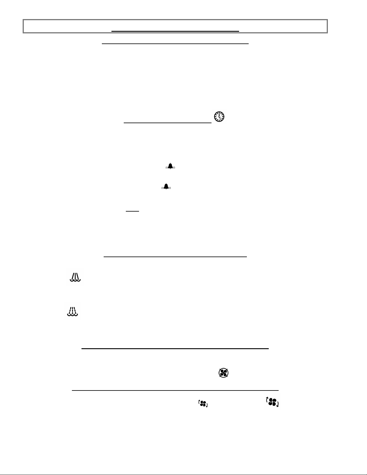
COOKING TIMER
Set the baking time required with the small push button on the timer. The green display is the setting
time and the red display is the countdown time (Ex: 25 minutes = set 2500 on green display).
After setting: Push the button, then when the time expires, the buzzer will ring.
Push the button again to stop the buzzer.
If you want to restart the time in the middle of the countdown, press on the yellow RST
button on the timer.
P.S. The timer is simply a reminder for the approximate duration of the baking time.
STEAM SWITCH SELECTOR
Two steam mode are available: Shot or Pulse steam.
Shot steam mode
This mode will inject one preset time shot of steam when selected, it is recommended to be use at the
beginning of the baking.
Pulse mode
This mode will pulse steam to keep moisture in the baking chamber during the baking time when
selected. This is recommended for product who needs to be cooked or baked with humidity.
DELAY SWITCH SELECTOR
The oven can work without ventilation for a period of 5 min. (electric oven) or 30 sec. (gas oven)
when the fan delay is selected
.
FAN SPEED SWITCH SELECTOR
The oven fan can work in LOW or HIGH speed mode. With the fan speed selector switch
you can select the fan velocity according to your product.
Page 12
A-9
OPÉRATION DU FOUR
1. Démarrer le four (tourner le sélecteur à la position ‘’1’’).
•
La lumière à l'intérieur du four doit allumer.
2. Ajuster le thermostat à la température désirée (voir FONCTIONNEMENT DU THERMOSTAT).
N.B. L'affichage digital doit être allumé. Si ce n'est pas le cas, vérifier le disjoncteur situé sur
le panneau avant.
3. Laisser chauffer jusqu'à ce que la température de cuisson soit stable, une lumière verte située sur
le thermostat s'allumera pour l'indiquer. (Si l'afficheur du thermostat est allumé et que le four ne
produit pas de chaleur, il y a un problème, contacter une compagnie de service.)
4. Enfourner le four le plus rapidement possible afin d'éviter de faire sortir la chaleur du four.
5. Ajuster et démarrer la minuterie (voir les explications à la page A-10).
NOTE: À la fin du cycle, la minuterie n'arrête pas le four de chauffer. Elle ne fait qu'émettre un
avertissement sonore.
6. Attendre que les produits soient complètement cuits avant d'ouvrir les portes.
TRÈS IMPORTANT
Ce four est équipé d’une alarme de surchauffe afin d’éviter des bris de pièces causés par la chaleur
dans les contrôles avant. Si la lampe témoin avis de surchauffe à côté du thermostat est allumée et
qu’une sonnerie se fait entendre; référez-vous à la section Dépannage.
FONCTIONNEMENT DU THERMOSTAT
Afin d'obtenir une très bonne stabilité thermique, nous
utilisons un contrôleur de température digital associé à un
thermocouple. Le thermostat Omron E5CS maintient la
température au point de réglage SP (set point).
En tout temps, le contrôleur de température affiche la
température du four et une flèche indique si elle est
supérieure ou inférieure au point de réglage SP (set point).
Une lumière verte indique que la température est à ± 1% de
la valeur SP.
Pour régler la température, il suffit de presser sur le
bouton de gauche pour sélectionner la variable (SP) et
d'utiliser les flèches pour régler la valeur. Il faut ensuite
revenir au mode de fonctionnement normal en appuyant à
nouveau sur le bouton de gauche.
Page 13
A-10
INSTRUCTIONS POUR FOUR
OUVERTURE ET FERMETURE DES PORTES
Pour ouvrir les portes: Ouvrir une des portes de 2 pouces et attendre 2 secondes afin de permettre
au ventilateur de diminuer sa vitesse avant d’ouvrir complètement.
Pour fermer les portes : Fermer la première porte complètement et la deuxième jusqu'à 2 pouces et
attendre 2 secondes avant de fermer ensuite maintenir fermer 2 secondes.
N.B. Ouvrir les portes le moins souvent possible car ceci affecte la cuisson des produits
(perte de chaleur).
MINUTERIE DE CUISSON
Le mécanisme doit être ajusté au temps désiré (utiliser les boutons en bas de l'affichage).
L’affichage vert est le temps désiré et l’affichage rouge est le décompte du temps de cuisson avant que
la sonnerie ne se fasse entendre. Exemple: 25 minutes = 2500 (sur la minuterie)
Après ajustement: Pressez le bouton poussoir . Quand le temps sera expiré, la sonnerie de la
minuterie retentira.
Pressez le bouton poussoir à nouveau pour l'arrêter.
Si vous désirez repartir le décompte de nouveau avant la fin du décompte, appuyer
sur le bouton RST jaune sur la minuterie et le temps va repartir de nouveau
automatiquement.
N.B. La minuterie est tout simplement une aide ou un guide pour la durée approximative de la
cuisson. Elle ne provoque pas l’arrêt du four.
INTERRUPTEUR SÉLECTEUR DE VAPEUR
Deux mode de vapeur disponibles: Injection unique ou Pulse.
Mode unique
Ce mode, lorsque sélectionné, injecte la vapeur pour un temps préréglé, recommander en début de
cuisson.
Mode Pulse
Ce mode, lorsque sélectionné, injecte une légère vapeur par intervalle préréglé afin de garder une
humidité constante durant la cuisson.
INTERRUPTEUR SÉLECTEUR DÉLAI DU VENTILATEUR
Le four peut fonctionner sans ventilation pour une période de 5 min. (four électrique) ou 30 sec. (four
au gaz) lorsque l’interrupteur est en position délai du ventilateur .
INTERRUPTEUR SÉLECTEUR DE VITESSE DU VENTILATEUR
Le ventilateur du four peut fonctionner en mode basse ou haute vitesse . À l’aide du
sélecteur de vitesse, vous pouvez choisir la vitesse désirée selon vos produits.
Page 14
A-11
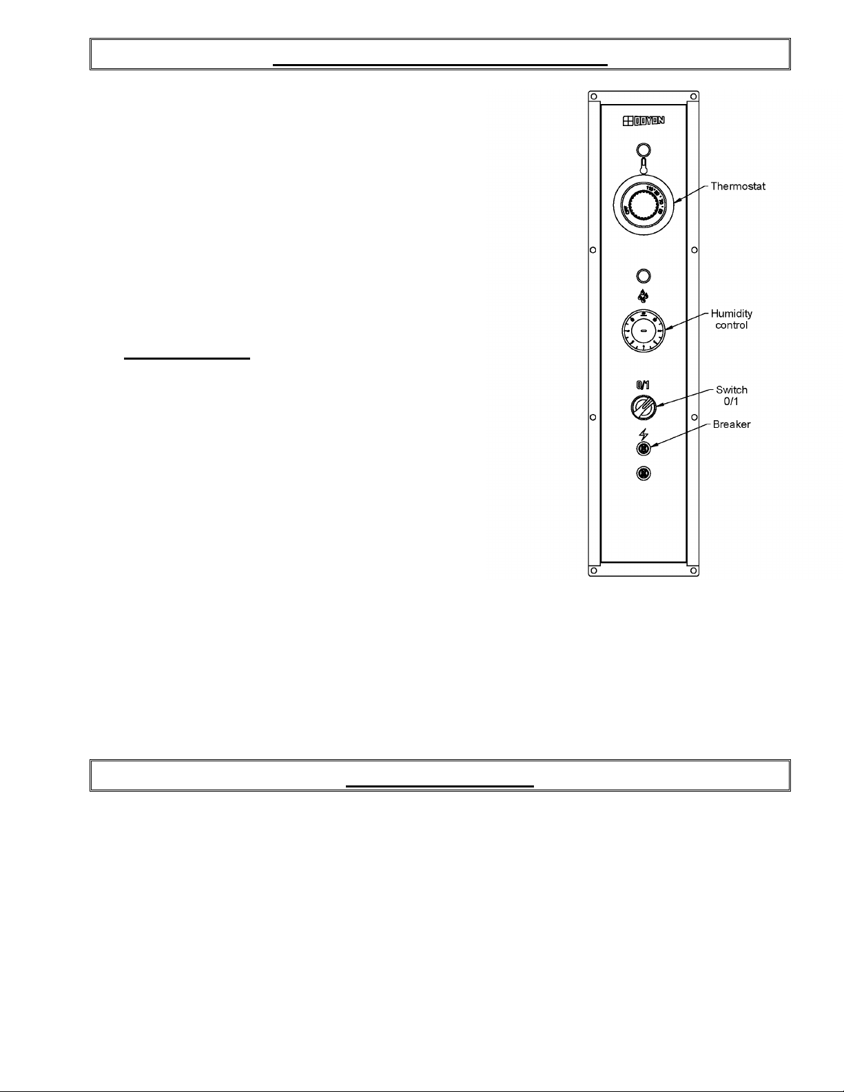
OPERATION OF THE PROOFER
1. Switch "ON" (1).
2. Set the thermostat control at 100° F.
3. Set the humidity control at approximately:4 or 5 for CAOP6 and
CAOP12
4. If there is too much fog and water drips from the glass doors, adjust
humidity control to a lower number.
5. When the temperature is stabilised, put the products in the proofer.
(Leave them inside until they are ready to bake.)
IMPORTANT: When proofing cycle is completed, turn the
6.
humidity switch to "OFF" and let the motor blower and air heat
element run for 10-15 minutes to let dry the proofer. Then, turn the
main switch ‘’OFF’’ (0), and leave the door ajar to prevent
moulding.
When the proofer is not in operation, open the doors to let out the humidity and to prevent
mould.
P.S. The doors should not be opened unnecessarily to conserve the heat and humidity in the proofer.
Every day cleaning of the water pan under the proofer's doors should be exercised.
POWER FAILURE
When the power comes back, the proofer will start automatically. Then it’s recommended to turn OFF
the unit to avoid it starting without supervision.
Page 15

OPÉRATION DE L'ÉTUVE
1. Placer l'interrupteur à "ON" (1).
2. Placer le bouton du thermostat à 100°F.
3. Placer le bouton d'humidité à approximativement 4 ou 5 pour
CAOP6 et CAOP12
4. S'il y a trop de vapeur, l'eau condensera sur la vitre et des
gouttelettes glisseront. Il faut alors diminuer le réglage d'humidité.
5. Quand la température est stabilisée, charger l'étuve
(Laisser le produit à l'intérieur jusqu'à ce qu'il soit prêt à cuire).
IMPORTANT: Quand l'utilisation est terminée, mettre le
6.
contrôle d’humidité à "OFF" et laisser fonctionner la chaleur et le
ventilateur pour 10-15 minutes. Après cette période, mettre
l’interrupteur principal de l’étuve à "OFF" (0) et laisser les portes
entrouvertes. Ceci permettra de minimiser la formation de
moisissure.
A-12
Lorsque l’étuve ne fonctionne pas, ouvrir les portes pour laisser sortir l’humidité afin de prévenir la
formation de moisissure.
N.B. Bien fermer les portes et ne pas les ouvrir inutilement pour conserver la chaleur et la vapeur
dans l'étuve.
Bien nettoyer à tous les jours le récupérateur d'eau situé en dessous de la porte.
PANNE DE COURANT
L’étuve est sécuritaire même lors d’une panne de courant. Lorsque l’alimentation revient, l’étuve se
remet en marche automatiquement selon le réglage. Il est donc nécessaire de mettre le sélecteur à
‘’ARRÊT’’ afin d’éviter que l’appareil redémarre sans surveillance.
Page 16
A-13
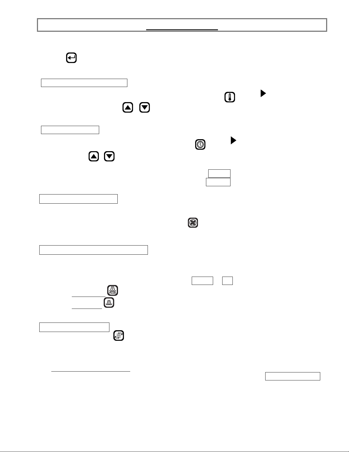
ECM-1 PROGRAMMABLE CONTROL - OPERATING MODES
The Doyon ECM-1 controller has two operation modes Manual and Programmable.
MANUAL: to use all functions without using recipe program.
PROGRAMMABLE: to use with recipe cook program.
Program capacity
□ Programs #1 to #99 can have up to 10 steps each (low-level programmable).
□ Program #0 is always used as the default Manual Cook mode setting (single-step).
OFF MODE
Display/LED
□ Display shows OFF.
□ All other LEDs are off, except the
Press on
point (except if you select a cook program referred in How to Select a Cook Program or the Manual
Mode section).
To switch the oven OFF Press the RED stop button and hold it for 3 seconds. The oven will run on
cool down mode until it reaches 250°F and then switch OFF.
To change the temperature set point or timer setting press and hold for 3 sec. on
appears on the left side of the display, press on / (up / down) to select the desired temperature
set point or timer setting. The new set point or time setting will be automatically saved after 3 seconds.
Display/LED
□ Display scrolls current cook program name (by default MANUAL if no program yet selected).
□ 2nd line shows actual oven temperature.
□ Heat and Fan, LED follows output state.
□ Ready LED blinks.
□ Stop LED is on.
This is the default mode when the controller powers up.
Start key LED.
(start) when the oven is ON, the oven will run on preheat mode at the manual mode set
or
. When
When probe temperature reaches set point, the unit beeps 5 seconds, the ready LED stays on and the
oven goes into COOK MODE.
When the oven is ON, a 3 second long press of red Stop key will go to Cool Down mode if the oven
temperature is over 250°F / 120°C before going to OFF mode. If the temperature is bellow 250°F /
120°C, the oven goes directly to the OFF mode.
DOOR SWITCH
□ If door is opened:
○ Display scrolls DOOR OPEN.
○ All outputs are turned off (unless in Cool Down mode, then fan remains on).
○ All timers pause until the door is closed.
□ When the door is closed, a short delay must expire before all accessories resume normal
operation.
Page 17
A-14
How to select a cook program or the Manual Mode
To select a recipe program, enter the recipe number with the numeric keypad and press (Start) or
use the Next or Previous arrow
confirm with the (Start) key.
When the recipe is selected, it will be active in the preheat mode until the set point in the first step is
reached. The LED of the red Stop key will light. The recipe will start only when the LED of the key
(Start) is lit.
To go back to the Manual Mode, press on the key and then on the (Start) key or use the Next
or Previous arrow
key (Start).
to jump from one to an other program without having to confirm with the
to jump from one to an other program without having to
Page 18
A-15
MANUAL MODE
This mode is used to work one step program.
Press on (Start) when the oven is ON, the oven will run on preheat mode at the manual mode set
point (by exception if you select a cook program referred in the PROGRAM MODE section).
TEMPERATURE FUNCTION
To change the temperature set point, press and hold for 3 sec. on . When
side of the display, press on / (Up / Down) to select the desired temperature set point. The
new set point will be automatically saved after 3 seconds.
TIMER FUNCTION
To change the time setting, press and hold for 3 sec. on
display, press on
automatically saved after 3 seconds.
□ If time is less than 60 minutes, it will be displayed as MM.SS
□ If time is 60 minutes or more, it will be displayed as HH:MM
FAN DELAY FUNCTION
□ The fan is always in function, but you can delay the fan for 5 min. (electric oven) or
30 sec. (gas oven) by pressing the Delay key . After this delay, the fan will run normally.
By pressing a second time on the key before the end of the delay, the fan will remain in function.
STEAM GENERATION FUNCTION
/ (Up / Down) to select the desired time setting. The new time setting will be
When
.
appears on the left side of the
appears on the left
□ Steam output can be turned on only if oven’s temperature >= steam threshold
(300°F /149°C).
□ Steam output can be turned on only if fan is on PULSE
○ Pulse Steam
○ Shot steam : steam output is turned on for duration of preset time.
□ Note: Steam and Pulse-Steam in Manual Mode will force Fan On.
FUNCTION CHARIOT
This function is available only with ovens using a rotating rack. This function allows to start and stop
the rack.
Food Probe in Manual Mode
○ When activated, the food probe temperature can only be used in mode MONITOR ONLY.
This will indicate the internal food temperature, not the cooking. To control cooking, use
the Programming mode.
: will turn on and off the steam output continuously if pressed again.
or ON.
Page 19

A-16
PROGRAM MODE
This mode is used to program a Cook Recipe.
Cook Program structure
A cook program consists of a name as well as a number of steps. The name is pre-programmed into
the unit (each name can have up to 30 characters). Each step has the following programmable
parameters:
Oven temperature: the oven set point for this step.
Food temperature: the food temperature at which this step will end.
Time: the time duration for the current step.
Steam: the time steam is injected into the oven at the beginning of the step.
Fan: fan mode.
Aux.: on or off during step (only programmable via PC).
Rack: on or off during step.
Step End: user action needed at the end of step.
Programming
LED/Display
□ 1st line displays currently selected parameter’s value.
□ 2nd line displays current step.
Keys
□ To program or modify a recipe program, select the recipe name first, press and hold for 3
seconds on the Program key. This will give you access to the recipe program. If no change
is made in the recipe during more than 5 seconds, the controller will exit the recipe program
mode by itself and go back to standby mode.
□ All parameters can be programmed in any order within a step.
To program or modify a recipe, follow these steps :
□ Use the parameter keys (Temperature, Time, Steam, Pulse-Steam, Fan, Rack, or Step End) to
display and change its value.
○ Temperature key is used twice to program 2 parameters: Oven Set Point and Food
Temperature.
□ Use the Up / Down keys to change the current parameter.
□ Use the Previous / Next keys to change the current step number.
□ If Step End key is set to LAST
more steps may follow in the program.
□ After last step is programmed, hold the Program key for 3 seconds to exit programming
mode.
Valid programming ranges
Temperature
□ 50-500°F / 10-260°C
Food Temperature
□ 125-225°F / 51-107°C, must be enabled in Low-level programming to be used.
Time
□ Time is programmed in HH:MM.SS
□ Time can be programmed at any value between 00:00 minimum and 12:00 maximum.
□ Default is 00:00 for all steps / programs.
, it is considered to be the last step of the program even though
Page 20

A-17
Steam
□ 1st parameter can be: OFF, ON, PULSE.
○ If OFF, steam remains off for duration of step.
○ If ON, steam remains on for duration of step.
○ If PULSE, pulsed steam is enabled for duration of step.
□ Default is OFF for all steps / programs (no steam).
Pulse-Steam
□ Steam parameter (see above) must be set to PULSE.
□ Pressing Pulse-Steam allows programming TON 0.02 seconds by default.
□ Pressing Pulse-Steam a 2nd time allows programming TOFF 0.30 seconds by default.
□ Default is OFF for all steps / programs (no steam).
Fan
□ 1st parameter can be: OFF, ON, PULSE.
○ If OFF, fan remains off for duration of step.
○ If ON, fan remains on for duration of step.
○ If PULSE
, pulse fan is enabled (pulse mode for duration of step).
■ Pressing Fan a 2nd time allows programming TON 02.30 minutes by default.
■ Pressing Fan a 3
rd
time allows programming TOFF from 0.25 seconds by default.
□ Default is PULSE for all steps/programs.
Rack
(Functional only with oven models with rotating racks).
□ Rack must be enabled in low-level programming to be useable.
□ This can be ON or OFF for each step.
□ Default is ON for all steps / programs, if enabled in low-level programming.
Step End
□ Step End defines what happens with the end of a Cook Program Step (Stop key is used to
program Step End parameter).
○ AUTO: nothing happens, automatically move on to the next step (buzzer output remains
off).
○ WARN: move on automatically to the next step, but turn on buzzer output for 5 seconds.
○ MANUAL: activates buzzer output until user manually presses Start key to enable next
step.
○ LAST: activate buzzer output until user manually presses Stop key to end the recipe.
□ Default is AUTO
for all steps / programs.
Food Probe in Programming Mode
□ Food temperature can be programmed to the following settings OFF ON MONITOR.
○ ON
: using food temperature’s programming set point to end the current step at that
temperature.
○ OFF: default for all steps / programs.
○ MONITOR
: to ignore food probe temperature, but still display the information if
requested.
Page 21

A-18
COOK MODE
reminder, this mode can cook without using the timer.
Display/LED
□ The 1st line display depends on which view is selected:
○ Time View
○ Temperature View
○ Default View:
□ 2nd line shows current step number if oven is active.
□ Heat, Fan, Steam LED follows output state.
Keys
□ Note : Any changes to the various oven parameters in this mode will not be stored, but will
□ Press Temperature key to toggle the current view between Default, Cavity Probe and Food
Probe.
□ Press Time key:
○ Recipe active: toggles between default and remaining step time.
○ Last Step: toggles between the default and holding time.
□ 3-second long press of Temperature key to change set point (using Up/Down keys).
○ If enabled, a second press of the Temperature key will display the food probe setting.
□ 3-second long press of Time key to change timer’s value (using Up/Down keys).
□ Press Start key to start timer countdown (and rack rotation, if enabled).
□ 3-second long press of Next key to skip to next step.
□ 3-second long press of Previous key to go back to previous step.
□ Press Stop key to cancel countdown and return to idle.
□ 3-second long press of Stop key to go into Cool Down mode.
□ In Manual Mode only, Fan, Rack, Steam and Auto-Steam keys can be used to toggle their
respective output states.
□ Auto-Steam key will start/stop the auto-steam according to Low-level Steam Override TON
and TOFF parameters.
□ If oven is idle, a 5-second long press of the
currently selected Cook Program (or Manual Program).
□ When last step timer expires, the unit beeps 5 times and displays PRODUCT READY.
Pressing Stop red key will clear the message and resume idle.
When a Cook Program is used, if the timer is inactive, the oven is considered idle
(but it still maintains the set point). In Manual Mode, the timer is used only as a
■ Current time left in step is displayed, except in the last step, where hold time is
displayed.
■ Cavity temperature.
■ Current program name is displayed, except in last step, where PRODUCT READY
displayed.
simply take effect in the current step. This allows “tweaking” recipes from time to time
due to product variations or other factors. For changes to be stored, program mode must
be used.
Program key will enable Program Mode for the
is
Page 22

A-19
SYSTEM DIAGNOSTICS
Cavity Probe Alarm
□ Occurs when units detects a defective cavity or food temperature probe.
□ Unit goes into Off mode with error message CAVITY PROBE ERROR or
FOOD PROBE ERROR.
Accessory Failure
□ Occurs when input signal is no longer received.
□ Unit goes into Off mode with error message:
○ Accessory failure input # generates ACCESSORY 1 FAILURE.
○ Accessory failure input # generates OVERHEAT FAILURE over heat alarm in control
compartment (check cooling fan and filter).
LANGUAGE DISPLAY
Three languages are available. To change the language display, the controller must be at OFF mode.
Press and hold the key for 5 seconds and use
□ENGLISH, FRANCAIS, ESPANOL
Only the following message will be changed, you can only change the recipe name by using a PC.
/ keys to select the language.
□ English French Spanish
OFF ARRÊT APAGADO
ON MARCHE MARCHA
PULSE IMPULSION IMPULSO
AUTO AUTOMATIQUE AUTOMATICO
WARN AVERTISSEMENT ADVERTENCIA
MANUAL MANUEL MANUAL
LAST DERNIER ULTIMO
MONITOR MONITEUR MONITOR
COOLING DOWN REFROIDISSEMENT ENFRIAMIENTO
ECONOMY MODE MODE ECONOMIQUE MODO ECONOMICO
DOOR OPEN PORTE OUVERTE PUERTA ABIERTA
PRODUCT READY PRODUIT PRET PRODUCTO LISTO
CAVITY PROBE ERROR ERREUR DE SONDE DE ERROR SONDA DE
CAVITE CAVIDAD
FOOD PROBE ERROR ERREUR DE SONDE DE ERROR SONDA DE
NOURRITURE ALIMENTOS
ACCESSORY FAILURE 1 ECHEC ACCESSOIRE 1 FALLA ACCESORIO 1
ACCESSORY FAILURE 2 ECHEC ACCESSOIRE 2 FALLA ACCESORIO 2
Page 23

CONTRÔLE PROGRAMMABLE ECM-1 - MODES D'OPÉRATION
Le contrôleur ECM-1 Doyon est doté du mode de fonctionnement manuel et programmable.
MANUEL : pour l’utilisation des fonctions sans avoir de recettes à programmer.
PROGRAMMABLE : ce mode est utilisé pour programmer une recette de cuisson.
Capacité du programme
□ Le programme #0 est toujours utilisé comme programme par défaut du mode Cuisson Manuel
(une seule étape).
□ Les programmes de #1 à #99 peuvent contenir jusqu'à 10 étapes de fonctionnement par recette.
A-20
MODE ARRET
État d'affichage & DEL
□ L'écran affiche ARRET
□ Toutes les autres DEL sont éteintes, sauf celle de la touche
En appuyant sur (départ) quand le four est en marche, le four se met en mode préchauffage sur le
point de consigne du mode manuel sauf si un programme est sélectionné au préalable (voir plus bas
comment sélectionner une recette ou le Mode Manuel).
Pour mettre le four à l'arrêt appuyer sur le bouton rouge pendant 3 sec. Le four va se mettre en mode
de refroidissement et s'arrêter lorsque la température de la chambre atteindra 250°F.
Pour changer le degré de température ou le temps désiré, appuyez 3 sec. sur
apparaît à gauche de l'affichage, appuyez sur / (haut / bas) pour choisir le degré de
température et le temps désiré. La nouvelle consigne va s’enregistrer automatiquement après 3
secondes.
État d'affichage & DEL
□ L'écran défile le nom du programme de cuisson en cours (par défaut MANUEL si aucun
programme n'a été sélectionné).
□ La 2e ligne affiche la température actuelle du four.
□ Chaleur et Ventilateur, les DEL suivent l'état de leur sortie.
□ La DEL Prêt clignote.
□ La DEL Arrêt est allumée.
Fonction par défaut lors de l'alimentation
(départ).
ou
. Lorsque
Lorsque la température du four atteint le point de consigne, l'unité bip-bip pendant 5 secondes et
lorsque la DEL Prêt reste allumée et ne clignote plus, le four est prêt à être utilisé en MODE
CUISSON.
En appuyant 3 secondes sur la touche (arrêt rouge) quand le four est en marche, le Mode de
Refroidissement s'active si la température interne du four est supérieure à 250°F /120°C avant de se
mettre en MODE ARRÊT. Si la température est inférieure à 250°F /120°C, le four se met
immédiatement en MODE ARRÊT.
OUVERTURE DES PORTES
□ Si la porte est ouverte :
○ L'écran d'affichage défile PORTE OUVERTE.
○ Toutes les sorties ne sont pas en fonction.
○ Toutes les minuteries s'arrêtent et ne poursuivent que lorsque la porte est fermée.
□ Tous les accessoires reprennent leur état initial quelques secondes après avoir refermé la
porte.
Page 24

A-21
Comment sélectionner une recette programmée ou le Mode Manuel
Pour choisir une recette programmée, entrez le numéro de la recette à l'aide du clavier numérique et
appuyez sur (départ ou utilisez les flèches
avoir à le confirmer avec la touche (départ).
Lorsque la recette est choisie, elle s'active en mode préchauffage selon la programmation de la
recette. La DEL de la touche (arrêt rouge) est donc allumée et la recette ne peut être activée
seulement lorsque la DEL de touche (départ) est allumée.
Pour revenir au Mode Manuel, appuyez sur la touche et sur (départ) ou utilisez les flèches
pour sauter du programme sélectionné au programme manuel sans avoir à le confirmer avec
la touche (départ).
pour sauter d'un programme à l'autre sans
Page 25

MODE MANUEL
Ce mode est employé pour l’utilisation des fonctions sans avoir de recettes à programmer.
FONCTION TEMPÉRATURE
A-22
Pour changer le degré de température désiré, appuyez 3 sec. sur . Lorsque
de l'affichage, appuyez sur / (haut / bas) pour choisir le degré de température désiré. La
nouvelle consigne devrait s’enregistrer automatiquement après 3 secondes.
FONCTION MINUTERIE
Pour changer le temps de cuisson, appuyez 3 sec. sur
l'affichage, appuyez sur / (haut / bas) pour ajuster le temps de cuisson. La nouvelle consigne
devrait s’enregistrer automatiquement après 3 secondes.
□ Si le temps est moins que 60 minutes, le temps est affiché dans le format MM.SS
□ Si le temps est de 60 minutes ou plus, le temps est affiché dans le format HH:MM
FONCTION DELAI VENTILATEUR
□ Le ventilateur est toujours en fonction. Par contre, si l'utilisateur appuie sur la touche délai
ventilateur , le ventilateur s'arrêtera pour une période de 5 min. (four électrique) ou
30 sec. (four au gaz). Après ce délai, le ventilateur revient en marche.
En appuyant une seconde fois sur la touche avant la fin du délai, le ventilateur se remet en fonction.
Lorsque
.
apparaît à gauche
apparaît à gauche de
FONCTION GÉNÉRATION DE VAPEUR
□ La sortie Vapeur peut être activée seulement si la température du four ≥ (300ºF / 149ºC).
□ La génération de vapeur peut se faire de 2 façons :
○ Vapeur pulsée
mode programmation ou jusqu'à ce qu’on appuie à nouveau sur Vapeur Automatique en
Mode Manuel.
○ Injection unique à demande
□ Note: La vapeur pulsée ou la vapeur à la demande force le ventilateur à fonctionner.
FONCTION CHARIOT
Cette fonction est utilisée pour les modèles de four avec chariot rotatif seulement et permet d'activer
ou désactiver le chariot.
Sonde de nourriture en Mode Manuel
□ La température de la sonde de nourriture si activée peut être utilisée en mode MONITEUR
seulement. Ceci indique la température interne de la nourriture, mais ne contrôle pas la
cuisson. Pour contrôler la cuisson, il faut utiliser le mode programmable.
: la sortie Vapeur commute continuellement pour la durée de l'étape en
: la sortie Vapeur est activée pour la durée préréglée.
Page 26

A-23
MODE PROGRAMMABLE
Ce mode est utilisé pour programmer une recette de cuisson.
Structure d'un Programme de Cuisson
Un Programme de Cuisson consiste donc en un nom de recette qui est préenregistré dans le contrôle
(chaque nom peut contenir jusqu'à 30 caractères, PC requis). Les paramètres suivants peuvent être
programmés pour chacune des étapes d'une recette :
Température four : point de consigne du four pour cette étape.
Température nourriture : température de la sonde de nourriture où l'étape prendra fin.
Temps : la durée de l'étape en cours.
Vapeur : la durée de l'injection de vapeur à partir du début de l'étape.
Ventilateur : mode Ventilateur.
Aux. : activé ou désactivé durant l'étape (PC requis).
Plateau tournant : activé ou désactivé durant l'étape.
Fin d'étape : intervention de l'utilisateur requise à la fin de l'étape.
Programmation
Affichage / DEL
□ La 1
□ La 2
Touches
□ Pour programmer ou modifier une recette, sélectionnez le numéro de la recette désirée,
□ Aucun ordre particulier est nécessaire pour la programmation des paramètres dans une étape.
ère
ligne affiche la valeur du paramètre sélectionné à l'aide de la touche.
ème
ligne affiche l'étape en cours.
maintenez la touche Programme pendant 3 secondes pour avoir accès à la programmation
de la recette. Pendant la programmation, si aucune touche est utilisée après 5 secondes, le
contrôleur retournera de lui-même en mode attente.
Pour programmer ou modifier une recette suivre les étapes suivantes:
□ Utilisez les touches de paramètres (Température, Minuterie, Vapeur, Vapeur Automatique,
Ventilateur, Plateau ou Fin Étape) pour afficher et changer sa valeur.
○ La touche Température est utilisée à 2 reprises pour programmer 2 paramètres : point de
consigne du four et température de la sonde de nourriture si activée.
□ Utilisez les touches Haut / Bas pour modifier la valeur du paramètre en cours.
□ Utilisez les touches Précédent / Suivant pour changer de numéro d'étape.
□ Si la touche Fin Étape est réglée à DERNIER, c'est considéré comme étant la dernière étape
du programme même si d'autres étapes suivent dans le programme.
□ Après la programmation de toutes les étapes, maintenez la touche
Programme pendant 3
secondes pour quitter le mode programmation.
Plages de valeurs permises
Température
□ 50-500°F/10 -260°C
Température de la sonde de nourriture
□ 125-225°F / 51-107°C, doit être activée dans la programmation de bas niveau afin d'être
utilisée.
Temps
□ Le temps est programmé sous le format HH : MM.SS.
□ Le temps peut être programmé à toutes les valeurs entre 00:00 minimum et 12:00 heures
maximum.
□ Le temps par défaut est 00:00
pour tous les programmes / étapes.
Page 27

Vapeur
□ Pour le 1er paramètre, les choix sont : MARCHE, ARRET, PULSE.
○ ARRET : la vapeur reste fermée pour toute la durée de l'étape.
○ MARCHE : la vapeur reste active pour toute la durée de l'étape.
○ PULSE
□ ARRET
: la vapeur est pulsée pour toute la durée de l'étape.
: par défaut pour toutes les étapes / programmes (pas de vapeur).
Vapeur-Pulsée
□ Le paramètre de Vapeur doit être réglé à PULSE.
□ Appuyer sur la touche Vapeur-pulsée permet de programmer TON 0.02 secondes par défaut.
□ Appuyer sur touche Vapeur-pulsée une 2
ème
fois permet de programmer T
0.30 secondes
OFF
par défaut.
□ ARRET par défaut pour toutes les étapes / programmes (pas de vapeur pulsée).
Ventilateur
□ Pour le 1er paramètre, les choix sont : MARCHE, ARRET, PULSE
○ ARRET : le ventilateur est arrêté pour toute la durée de l'étape.
○ MARCHE : le ventilateur tourne pour toute la durée de l'étape.
○ PULSE : le ventilateur tourne à intermittence pour toute la durée de l'étape.
■ Appuyer sur la touche Ventilateur une 2
ème
fois permet de programmer TON du
ventilateur 2.30 minutes par défaut.
ème
■ Appuyer sur la touche Ventilateur une 3
ventilateur 0.30
par défaut.
fois permet de programmer T
□ PULSE par défaut pour toutes les étapes / programmes.
Chariot
(pour les modèles de four avec chariot rotatif seulement)
□ Afin de pouvoir utiliser le Chariot, ce dernier doit être activé dans la programmation de Bas
Niveau.
□ Le Chariot peut prendre l'état MARCHE ou ARRET pour chacune des étapes.
□ Le Chariot prend l'état MARCHE par défaut pour toutes les étapes / programmes si activé
dans la programmation de Bas Niveau.
Fin D'étape
□ Étape Fin défini ce qui se produit avec l'avertisseur à la fin d'une étape d'un Programme de
Cuisson ( la touche arrêt est utilisée pour programmer le paramètre Étape Fin ).
○ AUTOMATIQUE
: rien ne se passe, allez directement à l'étape suivante ( l'avertisseur ne
se fait pas entendre ).
○ AVERTISSEMENT
: passe directement à l'étape suivante, mais l'avertisseur émet un bruit
pour une période de 5 secondes.
○ MANUEL
: l'avertisseur se fait entendre jusqu'à ce que l'utilisateur appuie sur la touche de
départ, déclenchant du même coup le passage à l'étape suivante.
○ DERNIER : l'avertisseur se fait entendre jusqu'à ce que l'utilisateur appuie sur la touche
arrêt, mettant ainsi fin au Programme de Cuisson.
○ AUTOMATIQUE
: par défaut pour toutes les étapes / programmes.
OFF
A-24
du
Sonde de nourriture en mode programmable
□ La Température de la sonde de nourriture peut être programmée des manières suivantes :
○ MONITEUR : indique la température interne de la nourriture, ne contrôle pas la cuisson.
○ ON
: prend charge de la cuisson et lorsque la température interne de la nourriture atteint
sa consigne définie dans la recette, elle met fin à la recette.
○ OFF
par défaut pour toutes les étapes / programmes.
Page 28

A-25
MODE CUISSON
Fonction par défaut lors de l'utilisation d'un Programme de Cuisson (ou Mode
Manuel). Si la minuterie n'est pas active, le four est considéré inactif (mais le
point de consigne est maintenu).
Affichage/DEL
□ L'affichage sur la 1
ère
ligne de l'écran dépend du type d'affichage sélectionné:
○ Temps
■ Un compte à rebours est affiché pour chacune des étapes, sauf pour la dernière étape
où c'est le temps de maintien qui est affiché.
○ Température
■ Température de la cavité.
○ Par défaut:
■ Le nom du programme en cours est affiché, sauf à la dernière étape, où PRODUIT
PRET est affiché.
□ La 2
ème
ligne affiche le numéro de l'étape en cours si le four est activé.
□ Les DEL Chaleur, Ventilateur et Vapeur suivent l'état de leur sortie.
Touches
□ Note : Dans ce mode, tout changement effectué sur les différents paramètres du four ne seront
pas conservés, mais prendront effet uniquement pour l'étape en cours. Cela permet un
ajustement ponctuel des recettes pour palier aux variations du produit et facteurs
divers. Le Mode Programmation doit être utilisé si les changements sont à garder en
mémoire.
□ L'affichage bascule entre Défaut, Sonde de cavité et Sonde de nourriture si activée en
appuyant sur la touche température.
□ En appuyant sur la touche de minuterie :
○ Recette active : bascule entre l'affichage par défaut et compte à rebours (étape).
○ Dernière étape : bascule entre l'affichage par défaut et le temps de maintien.
□ Le changement du point de consigne s'effectue en appuyant 3 secondes sur la touche
température (modifiez la température à l'aide des touches haut / bas).
○ Si activée, une seconde pression sur la touche température permet d'afficher l'ajustement
de la sonde de nourriture.
□ L'ajustement de la minuterie s'effectue en appuyant 3 secondes sur la touche de minuterie (à
l'aide des touches haut / bas).
□ Le compte à rebours de la minuterie (et la rotation du plateau, si activée) débute en appuyant
sur la touche départ.
□ Pour passer directement à l'étape suivante, appuyez 3 secondes sur la touche Suivant.
□ Pour revenir à l'étape précédente, appuyez 3 secondes sur la touche Précédent.
□ Pour annuler le compte à rebours et retourner à la température de maintien, appuyez sur la
touche Arrêt.
□ Le mode de Refroidissement s'active en appuyant 3 secondes sur la touche d'Arrêt.
□ En mode Manuel seulement, les touches Ventilateur, Plateau, Vapeur et Vapeur Automatique
peuvent être utilisées pour basculer vers leurs états respectifs.
□ La touche Vapeur Automatique va démarrer / arrêter la vapeur selon les paramètres TON et
TOFF selon le niveau de vapeur.
□ Si la température du four est en maintien, l'activation du Mode Programmation pour le
Programme de Cuisson (ou Programme Manuel) venant d'être sélectionné s'effectue en appuyant
5 secondes sur programme
.
□ Lorsque le compte à rebours de la dernière étape se termine, l'unité émet 5 bips et affiche
PRODUIT PRÊT
. Si la touche minuterie est active, le compte à rebours indique la période
écoulée depuis la fin de la recette. En appuyant sur la touche (arrêt rouge), le message et le
temps s'efface et la température de maintien est conservée.
Page 29

A-26
DIAGNOSTIQUE DU SYSTÈME
Alarme de sonde de cavité
□ Survient lorsque l'unité détecte une défectuosité en ce qui concerne la sonde de cavité ou la
sonde de nourriture.
□ L'unité se met en mode Arrêt et affiche le message ERREUR DE SONDE DE CAVITE ou
message ERREUR DE SONDE DE NOURRITURE
Défectuosité accessoire
□ Survient lorsque l'unité ne reçoit plus le signal d'entrée pour un accessoire donné.
□ L'unité se met en mode Arrêt et affiche le message :
ECHEC ACCESSOIRE # (# correspond au numéro de l'accessoire en cause).
ECHEC SURCHAUFFE alarme de surchauffe dans le compartiment de contrôle (Vérifiez
ventilateur de refroidissement et filtre).
LANGUE D'AFFICHAGE
POUR CHANGER LA LANGUE D'AFFICHAGE
Trois langues sont disponibles. Pour changer la langue d'affichage, mettre le four en mode ARRÊT.
Ensuite, appuyez et maintenez la touche pour 5 secondes et appuyez sur les touches /
pour changer la langue. □ENGLISH, FRANCAIS, ESPANOL seulement les messages de l'interface ci
bas seront changés, les noms de recettes doivent être fait à partir d'un PC.
□ English French Spanish
OFF ARRÊT APAGADO
ON MARCHE MARCHA
PULSE IMPULSION IMPULSO
AUTO AUTOMATIQUE AUTOMATICO
WARN AVERTISSEMENT ADVERTENCIA
MANUAL MANUEL MANUAL
LAST DERNIER ULTIMO
MONITOR MONITEUR MONITOR
COOLING DOWN REFROIDISSEMENT ENFRIAMIENTO
ECONOMY MODE MODE ECONOMIQUE MODO ECONOMICO
DOOR OPEN PORTE OUVERTE PUERTA ABIERTA
PRODUCT READY PRODUIT PRET PRODUCTO LISTO
CAVITY PROBE ERROR ERREUR DE SONDE DE ERROR SONDA DE
CAVITE CAVIDAD
FOOD PROBE ERROR ERREUR DE SONDE DE ERROR SONDA DE
NOURRITURE ALIMENTOS
ACCESSORY FAILURE 1 ECHEC ACCESSOIRE 1 FALLA ACCESORIO 1
ACCESSORY FAILURE 2 ECHEC ACCESSOIRE 2 FALLA ACCESORIO 2
Page 30

A-27
ECM-2 PROGRAMMABLE CONTROL - OPERATING MODES
1. Turn the main switch "ON" (1).
2. The light inside the proofer will turn ON and the digital control will indicate a code. Then,
"PREH" will flash.
3. "PREH" will be displayed on the control until it reaches the set temperature.
4. To check and modify:
Temperature settings : Press and hold down for 2 seconds the temperature key
and adjust with the UP and DOWN arrows. Then, press
temperature key to save data or " red
without saving.
Humidity settings :Press and hold down for 2 seconds the humidity key and
adjust with the UP and DOWN arrows. Then, press humidity
key to save data or "red " to exit without saving.
5. When the control reaches the set parameters, "PREH" will disappear and the timer display will
appear.
To start the timer, press " green ", the timer will stop blinking and start countdown.
At the end of the countdown an alarm will go off and " READY " will appear on the display. Press
" red " to stop the alarm.
6. When proofing cycle is completed, turn "OFF" (0) the switch.
When the proofer is not in operation, open the doors to let out the humidity and to prevent
mould.
P.S. The doors should not be opened unnecessarily to conserve the heat and humidity in the proofer.
Every day cleaning of the water pan under the proofer's doors should be exercised.
" to exit
Page 31

CONTRÔLE PROGRAMMABLE ECM-2 - MODES D'OPÉRATION
1. Placer l'interrupteur à "ON" (1).
2. La lumière à l’intérieur de l’étuve s’allumera et le contrôle digital affichera un code.
Ensuite," PREH " clignotera.
3. Le contrôle affichera " PREH " jusqu’à ce que l’étuve atteigne les paramètres d’étuvage
demandés.
4. Pour vérifier et modifier :
La température : Appuyer sur le bouton température pendant 2 secondes et ajuster
avec la flèche HAUT et BAS. Ensuite, appuyer sur le bouton
température pour sauvegarder les informations ou sur
A-28
"
L’humidité : Appuyer sur le bouton humidité pendant 2 secondes et ajuster
5. Lorsque ces paramètres seront atteints, " PREH " disparaîtra et le temps pré-ajusté de la
minuterie s’affichera.
Pour démarrer la minuterie, appuyer sur le " vert ". Le temps sur la minuterie cessera de
clignoter et commencera son décompte. À la fin du décompte, il y aura un signal sonore et
" READY" s’affichera. Appuyer sur le " "rouge pour l’arrêter.
6. Quand l'utilisation est terminé, mettre l'interrupteur à "OFF" (0).
Lorsque l’étuve ne fonctionne pas, ouvrir les portes pour laisser sortir l’humidité afin de prévenir la
formation de moisissure.
N.B. Bien fermer les portes et ne pas les ouvrir inutilement pour conserver la chaleur et la vapeur
dans l'étuve.
Bien nettoyer à tous les jours le récupérateur d'eau situé en dessous de la porte.
rouge " pour quitter sans enregistrer.
avec la flèche HAUT et BAS. Ensuite, appuyer sur le bouton
humidité pour sauvegarder les informations ou sur " rouge
" pour quitter sans enregistrer.
Page 32

A-29
TROUBLESHOOTING
BEFORE CALLING FOR SERVICE
ANSWERS TO MOST FREQUENT QUESTIONS
Always cut off the main power before replacing any parts. Take care of water and electric wire
supply system when pulling the oven.
Control parts on the front and proofer
control:
Motor system on the back of the oven:
Questions Solutions
The oven does not turn on.
The oven does not produce heat.
The rack does not rotate
Uneven baking.
Remove the side panels of the oven and the
proofer by screwing out the screws.
Pull the oven and screw out the panels.
Check the breakers on the front panel.
Check the breakers of the building.
Check if the doors are tightly closed.
Check the motor fuses and the overload relays
located in the electrical control panel.
1. If the oven blowers are on
• Make sure: the thermostat is adjusted to a
temperature high enough to turn on the pilot
light.
2. If the oven blowers are not on
• Check the overload relays located in the
control compartment. If anyone of these is
disengaged, call for a qualified technician.
Check if the doors are well closed.
Check the doors and rack switches.
Check the belt of the rack.
Check the fuse of the gearbox.
Make sure that the grills do not obstruct the air
flow. Do not use foil on the grills.
Verify the temperature of the oven by using an
oven thermometer and make sure that it is even
with the thermostat setting.
If the oven is baking too much on the sides, it is
possible that the fan is not cycling properly.
Verify if the motor turns 2.5 minutes in a
direction, stops 30 seconds and starts for 2.5
minutes in the opposite direction.
Page 33

A-30
If steam device of the oven does not work
properly.
If the OVERHEAT WARNING light is on,
and you hear the warning buzzer.
OPTIONAL
Manual fill water pan.
The warning red light in the front control
panel stays on when the water pan is full.
If there is no light in the proofer.
If there is no heat in the proofer.
If there is no humidity in the proofer.
The oven must have been heating for at least half
an hour before you use the steam system. If not,
water will appear at the bottom of the oven.
Check if the water supply valve (of the building)
is open.
Check if the water needle valve (of the oven) is
open one eighth of a turn. Just close it and open it
one eighth of a turn maximum.
Check the solenoid valve.
Be sure to inject steam while the fan is running.
Check if the cooling fan airflow is not obstructed.
Check the cooling fan if it is running. If the
malfunction light goes on, or if the audible
sound, appliance is malfunctioning. Turn off or
disconnect appliance form power supply and
have serviced by a electrician.
You have no more water in the principal water
pan.
Check if the water line is not in air lock
condition. Disconnect the water line at the inlet
of the green solenoid valve and clean the strainer
filter.
Also clean the principal water pan and the float
switch.
1. Verify every breaker in front of the proofer.
2. Verify the main proofer switch and the main
proofer contactor.
1. Verify every breaker in front of the proofer.
2. Verify whether the pilot light will function by
raising the thermostat to a higher setting. If
yes, verify element. If not, verify pilot light,
thermostat or contactors.
Verify whether the pilot light works when you
increase the humidity to the position high. If yes,
verify if water comes in the reservoir and check
the water level switch box and the float switch.
Verify if limestone obstructs the waterflow. If
the float switch is working fine, verify the
contactor P1 and the immersion element. If the
pilot light does not lite, verify the pilot light and
the infinite switch.
Page 34

A-31
DÉPANNAGE
AVANT D'APPELER LE DÉPARTEMENT DE SERVICE
SOLUTION AUX PROBLÈMES LES PLUS FRÉQUENTS
Toujours fermer l'approvisionnement du courant principal avant le remplacement de pièces.
Prendre garde aux tuyaux de gaz et d'eau avant de déplacer le four.
Les pièces de contrôle du four et de l'étuve:
Système de moteur à l'arrière du four:
Problèmes Solutions
Le four ne démarre pas.
Le four ne produit pas de chaleur.
Enlever le panneau de contrôle avant (dévisser les
vis du panneau et le basculer lentement vers l'avant).
Déplacer le four vers l'avant et dévisser le panneau
arrière.
Vérifier les disjoncteurs du panneau avant du
four.
Vérifier les disjoncteurs du bâtiment.
Vérifier si les portes sont bien fermées.
Vérifier les fusibles du moteur et les relais de
surcharge sur le panneau de contrôle arrière.
1. Si les moteurs tournent:
•
Assurez-vous que le thermostat est ajusté à
une température suffisamment élevée pour
faire allumer la lampe témoin.
Le rack ne tourne pas
Cuisson inégale.
2. Si les moteurs ne tournent pas:
•
Vérifier les relais de surcharge situés dans la
boîte de contrôle. Si un des relais n'est pas
engagé, appeler un technicien qualifié.
Vérifier si les portes sont bien fermées.
Vérifier les interrupteurs de portes et de rack.
Vérifier la courroie du rack.
Vérifier la fusible du moteur réducteur de vitesse.
Assurez-vous que les grilles permettent à l'air de
circuler librement. Ne recouvrez pas les grilles
de papier d'aluminium.
Vérifiez la température du four à l'aide d’un
thermomètre à four et comparez avec le réglage
du thermostat.
Si le four cuit trop au fond ou sur les côtés, le
temps de fonctionnement des ventilateurs peut
être déréglé. Il faut vérifier si le ventilateur
tourne bien 2.5 minutes dans un sens, arrêt de
30 secondes suivi de 2.5 minutes dans le sens
contraire.
Page 35

A-32
Le four ne produit pas de vapeur.
La lampe témoin AVIS DE SURCHAUFFE est
allumée et une sonnerie se fait entendre
RÉSERVOIR D’EAU À REMPLISSAGE
MANUEL OPTIONNEL
La lumière d’avertissement du réservoir d’eau à
l’avant du four reste allumée lorsque le
réservoir à l’arrière du four est plein.
Il n’y a pas de lumière dans l'étuve
(rien ne fonctionne).
Il n'y a pas de chaleur dans l'étuve
Il n'y a pas d'humidité dans l'étuve
La température du four doit être 300°F et plus
pour avoir le système de vapeur efficace.
Vérifiez si la valve à eau principale du four est
bien ouverte.
Assurez-vous d’injecter la vapeur seulement
lorsque le ventilateur du four fonctionne, la
lumière témoin du bouton de vapeur doit
s’allumer environ 15 secondes.
Vérifiez si la valve électrique fonctionne.
Vérifiez si la minuterie de vapeur fonctionne
dans la boîte de contrôle à l’arrière du four.
Vérifier si le conduit de la ventilation du
ventilateur de refroidissement n’est pas obstrué.
Vérifier si le ventilateur fonctionne. Si le témoin
rouge s'allume, ou un signal sonore se fait
entendre, fermer l'interrupteur ou débrancher
l'appareil et appeler un électricien.
Le réservoir principal est vide.
Vérifiez si la ligne d’eau entre les deux réservoirs
n’est pas bloquée (air lock).
Vérifiez si le filtre moustiquaire n’est pas bloqué.
1. Vérifiez les disjoncteurs sur le devant de
l'étuve.
2. Vérifiez l'interrupteur maître et le contacteur
maître de l'étuve.
1. Vérifiez les disjoncteurs sur le devant de
l'étuve.
2. Vérifiez si la lampe témoin allume lorsque
vous augmentez la température du thermostat
au maximum. Sinon, vérifiez la lampe témoin,
le thermostat et le contacteur des éléments
Vérifiez si la lampe témoin allume lorsque vous
augmentez l'intensité d'humidité au maximum. Si
oui, vérifiez si l'eau se rend au réservoir et
vérifiez l'interrupteur à niveau et actionnez-le.
Vérifiez si le calcaire n'obstrue pas le passage de
l'eau vers le réservoir secondaire. Si
l'interrupteur de niveau fonctionne bien, vérifiez
le contacteur P1 et l'élément d'immersion
Page 36

A-33
OVEN MAINTENANCE AND CLEANING
MAINTENANCE OF THE OVEN
• Grease the bottom bearing monthly and the top flange bearing yearly
• Check the tension of the belt yearly.
• It is recommended to use a water filter and to clean or replace it regularly to avoid accumulation of
minerals inside the unit.
• Once a year or as needed, clean the reservoir of the proofer
(see parts description for localisation).
Questions Solutions
Clean the inside of the oven and the proofer
with water and soap.
Take out the grills (the grills of the oven could
be cleaned with "Easy-Off").
After cleaning the inside of the oven, apply a
silicone base oven protector. It avoids food
from sticking to the metal.
Clean the oven windows with products like
Brasso or equivalents. They are copper
cleaners but good for this use
Clean the oven exterior with a stainless steel
cleaner.
We recommend and sell:
Dirt Buster III: Action foam cleaner
CHEMCO
Part number: NEB201
We recommend and sell:
316 Silicone base protector and lubricant for
oven
Dow Corning
Part number : EXS400
We recommend and sell:
Wright's: Cream copper cleaner
J.A. Wright & Co.
Part number : EXC300
We recommend and sell:
Stainless steel cleaner
SANY or CURTIS (comestible)
Part number : NES201
Page 37

ENTRETIEN ET NETTOYAGE DU FOUR
ENTRETIEN DE L'UNITÉ
•
Graisser régulièrement les roulements à billes des plateaux rotatifs. Graissez le roulement du bas
mensuellement et le roulement du haut annuellement.
•
Vérifier la tension de la courroie annuellement.
•
Il est recommandé d'utiliser un filtre à eau et de le remplacer régulièrement pour réduire les
accumulations de calcaire dans l'unité.
•
Une fois par année ou au besoin, nettoyer l'unité de vapeur de l'étuve.
(Voir description des pièces pour le localiser.)
Étape par étape Solutions
A-34
Nettoyer l'intérieur du four et de l'étuve avec de
l'eau et un détergent.
Enlever les grilles.
(Les grilles du four peuvent être nettoyées avec
du "Easy-Off".)
Après avoir nettoyé l'intérieur du four,
appliquer un protecteur sur les parois et les
grilles. Le produit empêche les aliments de
coller sur les parois du four.
Nettoyer les vitres du four avec du Brasso ou un
produit équivalent. Bien que ce soit des
nettoyeurs à cuivre, ils s'avèrent très efficaces.
Nettoyer l'extérieur du four avec un produit
d'entretien pour l'acier inoxydable.
Produit recommandé:
Dirt Buster III
Nettoyant à four à action moussante
No de pièce: NEB201
Produit recommandé:
Protecteur de silicone pour four
No de pièce: EXS400
Produit recommandé:
Nettoyeur pour vitres de four
No de pièce: EXC300
Produit recommandé:
Nettoyeur pour acier inoxydable
No de pièce: NES201
Page 38

A-35
BAKE CHART
BAKERY OVENS (Table as reference only)
Menu item
Bagels (16 per pan) 15 400 204
Dinner rolls (16 per pan) 15-18 350 177
Sub rolls 12" (10 per pan) 15-18 350 177
French Baguette (5 per pan) 20-25 350 177
Croissants (15 per pan) 12-15 350 177
9" Pies (6 per shelf) 30-35 375 190
Muffins (15 per pan) 18-22 325 163
Muffins (24 per pan) 18-22 325 163
Cakes 9" (6 per shelf) 18-22 350 177
Quiches 9" (6 per shelf) 30-35 350 177
Cookies (frozen) (18 per pan) 8-10 300 149
Danish (15 per pan) 12-15 350 177
Biscuits (fresh) (15 per pan) 8-10 350 177
Bread (4 strapped pan) 30-35 375 190
Cinnamon rolls (8/half pans) 15-18 325 163
Brownies (16.5 oz box) 12 350 177
Bake Time
Minutes
Bake TempºFBake Temp
ºC
Page 39

TABLEAU DE CUISSON
FOURS À PAIN ET PÂTISSERIE (Tableau à titre de référence seulement)
A-36
Item
Bagels (16 par plaque) 15 400 204
Pain à salade (16 par plaque) 15-18 350 177
Sous-marin 12" (10 par plaque) 15-18 350 177
Baguettes (5 par plaque) 20-25 350 177
Croissants (15 par plaque) 12-15 350 177
Tartes 9" (6 par tablette) 30-35 375 190
Muffins (15 par plaque) 18-22 325 163
Muffins (24 par plaque) 18-22 325 163
Gâteaux 9" (6 par tablette) 18-22 350 177
Quiches 9" (6 par tablette) 30-35 350 177
Biscuits (congelés) (18 par plaque) 8-10 300 149
Danoise (15 par plaque) 12-15 350 177
Biscuits (frais) (15 par plaque) 8-10 350 177
Pain (4 par plaque) 30-35 375 190
Brioche (8/demi-plaque) 15-18 325 163
Brownies (boîte de 16.5 oz) 12 350 177
Temps
cuisson min.
Temp.
cuisson ºF
Temp.
cuisson ºC
Page 40

B-1
B-1
SECTION B:
COMPONENT PARTS
PIÈCES COMPOSANTE
CA12 – FRONT VIEW
CA12 – VUE DE FACE
Page 41

Item Part Number Description Quantity
1 P1430FG LEFT DOOR CA OVEN 14 1/4" X 30 1/4" 2
2 P1430FD RIGHT DOOR CA OVEN 14 1/4" X 30 1/4" 2
3 PAR850 SWIVEL CASTER WITH BRAKE 2
4 PAR800 SWIVEL CASTER 2
5 QUP465 STAIN. STEEL TUBULAR HANDLE FOR DOOR 4
6 QUA200 DOOR MAGNET 8
7 QUP320 DOOR HINGE 8
8 ELM617 BLACK COVER FOR ELM616 1
9 ELM616 ELECTRONIC TIMER 1
10 ELM618 FIXING FOR PANASONIC TIMER 1
11 ELM629 ELECTRONIC TIMER 8 PIN SOCKET 1
12 ELP401 BLACK PUSHBUTTON PUSH-IN PUSH-OUT 1
13 ELI406 BASE WITH 1NO 2
14 ELT515 ELECTRONIC THERMOSTAT 1
15 ELM726 FIXING FOR OMRON TIMER 1
16 ELI404 SEL. 3 POS. RIGHT RETURN TOW. CENTER WHITE 1
17 ELL405 CONTACT BLOCK NO 3
18 ELL415 WHITE BASE LED 120V WITH 1NO 1
19 ELI403 BLACK SELECTOR 3 POS. 1
20 ELI413 BASE WITH 2NO 1
21 ELI402 BLACK SELECTOR 2 POS. 1
22 ELI409 CONTACT BLOCK NC 1
23 ELI408 MOUNTING BASE ONLY 1
24 ELP400 PUSH-BUTTON (BLACK) 1
25 ELB096 5A BREAKER 1
26 ELL650 RED PILOT LIGHT 250V 1
B-2
Item Numéro Pièce Description Quantité
1 P1430FG PORTE FOUR GAUCHE CA 14 1/4" X 30 1/4" 2
2 P1430FD PORTE FOUR DROITE CA 14 1/4" X 30 1/4" 2
3 PAR850 ROULETTE PIVOTANTE AVEC FREIN 2
4 PAR800 ROULETTE PIVOTANTE 2
5 QUP465 POIGNÉE DE PORTE TUBULAIRE (ACIER INOX.) 4
6 QUA200 AIMANT DE PORTE 8
7 QUP320 PENTURE DE PORTE 8
8 ELM617 COUVERCLE NOIR DE ELM616 1
9 ELM616 MINUTERIE ÉLECTRONIQUE 1
10 ELM618 FIXATION POUR MINUTERIE PANASONIC 1
11 ELM629 BASE 8 CON. POUR MINUTERIE ÉLECTRONIQUE 1
12 ELP401 BOUTON POUSSOIR NOIR POUSSE-POUSSE 1
13 ELI406 BASE AVEC 1NO 2
14 ELT515 THERMOSTAT ÉLECTRONIQUE 1
15 ELM726 FIXATION POUR MINUTERIE OMRON 1
16 ELI404 SÉLEC. BLANC 3 POS. RETOUR DROIT VERS CENTRE 1
17 ELL405 BLOC CONTACT NO 3
18 ELL415 BASE LED 120V BLANC AVEC 1NO 1
19 ELI403 SÉLECTEUR 3 POS. NOIR 1
20 ELI413 BASE AVEC 2NO 1
21 ELI402 SÉLECTEUR 2 POS. NOIR 1
22 ELI409 BLOC CONTACT NC 1
23 ELI408 BASE SANS CONTACT 1
24 ELP400 BOUTON POUSSOIR NOIR MOMENTANÉ 1
25 ELB096 DISJONCTEUR 5A 1
26 ELL650 LAMPE TÉMOIN ROUGE 250 V 1
Page 42

B-3
B-3
CA12 – BACK LEFT VIEW
CA12 – VUE ARRIÈRE GAUCHE
Page 43

B-4
Item Part Number Description Quantity
1 ELM760 COOLING FAN 120V 1
2 ELM400 ROLLER LEVER SWITCH 1
3 QURB100 FLANGE BEARING 1
4 QUP110 PULLEY 11 X 3/4 (HOLE) 1
5 QUC610 'V' BELT 78" 1
6 QUP100 PULLEY 2 X 3/4 (HOLE) 1
7 ELS887 SOLENOID VALVE WITH DIN CONNECTION 110/120V 50/60HZ 2
8 ELS889 JUNCTION BOX FOR ELS887 & ELS888 2
9 PLF100 WATER FILTER 1
10 ELV590 NEEDLE VALVE 2
11 ELM765 GEARBOX MOTOR 1/8HP 1PH 115V 1
12 ELP823B CONTROL PAN. DOUBLE 120/208-240V 1&3PH, WITH ATV & ZELIO, WITH BOX 1
13 ELP824B CONTROL PAN. DOUBLE 120/208-240V 1&3PH, WITH ATV, WITH BOX 1
14 ELM820M MOTOR 3/4HP 3PH 208/230/460V 60HZ/50HZ 2
15 ELT506 HIGH LIMIT SWITCH (500°F) 2
16 ELD081 FRAME AND LIGHT SOCKET 77-708 120V 4
OR ELD082 FRAME AND LIGHT SOCKET 77-708 230V 4
17 50010894 ASSY. FRAME,GLASS,GASKET AND SCREW FOR ELD081 & ELD082 4
18 ELM570 DOOR SWITCH 15A 2
19 ELT503 HIGH LIMIT SWITCH 140°F 1
20 ELS950 BUZZER 120V 3
Item Numéro Pièce Description Quantité
1 ELM760 VENTILATEUR DE REFROIDISSEMENT 120V 1
2 ELM400 INTERRUPTEUR À ROULEAU 1
3 QURB100 PALIER À BRIDE 4 TROUS 1
4 QUP110 POULIE 11 X 3/4 TROU 1
5 QUC610 COURROIE EN V 78 " 1
6 QUP100 POULIE 2 X 3/4 TROU 1
7 ELS887 VALVE À SOLENOÏDE AVEC CONNECTION DIN 110/120V 50/60HZ 2
8 ELS889 BOÎTE DE JONCTION POUR ELS887 ET ELS888 2
9 PLF100 FILTRE À EAU 1
10 ELV590 VALVE À POINTEAU 2
11 ELM765 MOTEUR RÉDUCTEUR 1/8HP 1PH 115V 1
12 ELP823B PAN. CONT. DOUBLE 120/208-240V 1&3PH, AVEC ATV & ZELIO, AVEC BOÎTIER 1
13 ELP824B PAN. CONT. DOUBLE 120/208-240V 1&3PH, AVEC ATV, AVEC BOÎTIER 1
14 ELM820M MOTEUR 3/4HP 3PH 208/230/460V 60HZ/50HZ 2
15 ELT506 THERMODISQUE HAUTE TEMPÉRATURE (500°F) 2
16 ELD081 SOCKET AVEC BOITIER DE LUMIERE 77-708 120V 4
OU ELD082 SOCKET AVEC BOITIER DE LUMIERE 77-708 230V 4
17 50010894 ASSY. COUVERT,VITRE,GASKET ET VIS POUR ELD081 & ELD082 4
18 ELM570 MICRO-INTERRUPTEUR 15A (PORTE) 2
19 ELT503 THERMODISQUE 140°F 1
20 ELS950 SONNERIE 120V 3
Note: As of April 2010, parts ELD081, ELD082 (#16) & 50010894 (#17) will replace parts
ELD050 & ELA275.
Note: À partir d’avril 2010, les pièces ELD081, ELD082 (#16) & 50010894 (#17) remplaceront
les pièces ELD050 & ELA275.
Page 44

B-5
B-5
CAOP6 – FRONT VIEW
CAOP6 – VUE DE FACE
Page 45

Item Part Number Description Quantity
1 P1430FG LEFT DOOR CA OVEN 14 1/4" X 30 1/4" 1
2 P1430FD RIGHT DOOR CA OVEN 14 1/4" X 30 1/4" 1
3 P1428EG LEFT DOOR PROOFER 14 1/4" X 28 3/4" 1
4 P1428ED RIGHT DOOR PROOFER 14 1/4" X 28 3/4" 1
5 STP510 DRIP PAN 1
6 PAP100 RUBBER 3/4" DIAM x 1/2" 1
7 STS900 DOOR HINGE STOPPER (STAINLESS) 2
8 PAR850 SWIVEL CASTER WITH BRAKE 1
9 PAR800 SWIVEL CASTER 1
10 QUP465 STAIN. STEEL TUBULAR HANDLE FOR DOOR 4
11 QUA200 DOOR MAGNET 8
12 QUP320 DOOR HINGE 8
13 ELL650 RED PILOT LIGHT 250V 2
14 ELT620 THERMOSTAT BEZEL 1
15 ELT627 THERMOSTAT 110°F 1
16 ELT628 THERMOSTAT KNOB 110°F 1
17 ELI240 INFINITY SWITCH KNOB 1
18 ELI220 HUMIDITY CONTROL 120V 1
19 50010610 PROTECTIVE GUARD FOR ELI220 & ELI230 1
20 ELI402 BLACK SELECTOR 2 POS. 1
21 ELI406 BASE WITH 1NO 1
22 ELB097 20A BREAKER 2
B-6
Item Numéro Pièce Description Quantité
1 P1430FG PORTE FOUR GAUCHE CA 14 1/4" X 30 1/4" 1
2 P1430FD PORTE FOUR DROITE CA 14 1/4" X 30 1/4" 1
3 P1428EG PORTE ÉTUVE GAUCHE 14 1/4" X 28 3/4" 1
4 P1428ED PORTE ÉTUVE DROITE 14 1/4" X 28 3/4" 1
5 STP510
6 PAP100 CAOUTCHOUC 3/4" DIAM x 1/2" 1
7 STS900 ARRÊT DE PORTE À PENTURE 2
8 PAR850 ROULETTE PIVOTANTE AVEC FREIN 1
9 PAR800 ROULETTE PIVOTANTE 1
10 QUP465 POIGNÉE DE PORTE TUBULAIRE (ACIER INOX.) 4
11 QUA200 AIMANT DE PORTE 8
12 QUP320 PENTURE DE PORTE 8
13 ELL650 LAMPE TÉMOIN ROUGE 250 V 2
14 ELT620 PLAQUE DE THERMOSTAT 1
15 ELT627 THERMOSTAT 110°F 1
16 ELT628 BOUTON DE THERMOSTAT 110°F 1
17 ELI240 BOUTON DE CONTRÔLE D'HUMIDITÉ 1
18 ELI220 CONTRÔLEUR D'HUMIDITÉ 120V 1
19 50010610 GARDE DE PROTECTION POUR ELI220-230 1
20 ELI402 SÉLECTEUR 2 POS. NOIR 1
21 ELI406 BASE AVEC 1NO 1
22 ELB097 DISJONCTEUR 20A 2
RÉCIPIENT À EAU EN STAINLESS / DESSOUS DE
PORTE 31"
1
Page 46

B-7
B-7
CAOP6 - BACK LEFT VIEW
CAOP6 – VUE ARRIÈRE GAUCHE
Page 47

B-8
B-8
Page 48

B-9
B-9
CAOP12 – FRONT VIEW
CAOP12 – VUE DE FACE
Page 49

B-10
Item Part Number Description Quantity
1 P1430FG LEFT DOOR CA OVEN 14 1/4" X 30 1/4" 2
2 P1430FD RIGHT DOOR CA OVEN 14 1/4" X 30 1/4" 2
3 PAP100 RUBBER 3/4" DIAM x 1/2" 4
4 STS900 DOOR HINGE STOPPER (STAINLESS) 4
5 PAR850 SWIVEL CASTER WITH BRAKE 2
6 PAR800 SWIVEL CASTER 2
7 P2857E PROOFER DOOR 28" X 57 1/4" (JAOP14, CAOP12) 1
8 QUP520 MAGNETIC HANDLE 1
9 STP500 DRIP PAN JAOP3, 6 AND 14 1
10 QUP320 DOOR HINGE 11
11 QUP465 STAIN. STEEL TUBULAR HANDLE FOR DOOR 4
12 QUA200 DOOR MAGNET 8
Item Numéro Pièce Description Quantité
1 P1430FG PORTE FOUR GAUCHE CA 14 1/4" X 30 1/4" 2
2 P1430FD PORTE FOUR DROITE CA 14 1/4" X 30 1/4" 2
3 PAP100 CAOUTCHOUC 3/4" DIAM x 1/2" 4
4 STS900 ARRÊT DE PORTE À PENTURE (ALUMINIUM) 4
5 PAR850 ROULETTE PIVOTANTE AVEC FREIN 2
6 PAR800 ROULETTE PIVOTANTE 2
7 P2857E PORTE D'ÉTUVE 28" X 57 1/4" (JAOP14, CAOP12) 1
8 QUP520 POIGNÉE MAGNÉTIQUE 1
9 STP500 PLAT D'ÉGOÛT JAOP3,6 ET 14 1
10 QUP320 PENTURE DE PORTE 11
11 QUP465 POIGNÉE DE PORTE TUBULAIRE (ACIER INOX.) 4
12 QUA200 AIMANT DE PORTE 8
Page 50

B-11
B-11
CAOP12 – BACK RIGHT VIEW
CAOP12 – VUE ARRIÈRE DROITE
Page 51

B-12
Item Part Number Description Quantity
1 ELM730 BLOWER ASSEMBLY FOR OVEN PROOFER 1
2 ELC860 CONTACTOR 2P 30A 110V 1
3 ELC617 BASE RELAY 8 PINS 1
4 ELC615 RELAY 10A 2P COIL 110V 1
5 ELC640 CONTROL RELAY BASE 1
6 ELC630 CONTROL RELAY 12A COIL 120V 1
7 ELD050 INCANDESCENT LIGHT SOCKET 6
8 ELA275 BULB 60W 130V 4
9 ELT505 THERMODISK 300°F 1
10 ELE130 COIL ELEMENT 120V 1500W 1
11 ELE165 IMMERSION ELEMENT 120V 1500W 1
12 ELS887
13 ELV590 NEEDLE VALVE 3
14 QUF350 ELECTRIC FLOAT 1
15 ELS889 JONCTION BOX FOR ELS887 & ELS888 2
16 PLF100 WATER FILTER 1
17 PLCU06 CONNECTOR FEMALE PIPE FOR TUBE 1
18 PLCU65 MALE TEE 1/4" 1
19 PLCU175
SOLENOID VALVE WITH DIN CONNECTION 110/120V
50/60HZ
BRASS FITTING END TUBE AND MALE PIPE CENTRE
TUBE
3
1
Item Numéro Pièce Description Quantité
1 ELM730 VENTILATEUR ASSEMBLÉ POUR ÉTUVE DE FOUR 1
2 ELC860 CONTACTEUR 2P 30A 110V 1
3 ELC617 BASE DE RELAIS 8 CONNECTEUR 1
4 ELC615 RELAIS 10A 2P BOBINE 110V 1
5 ELC640 BASE DE RELAIS DE CONTRÔLE 1
6 ELC630 RELAIS DE CONTRÔLE 12A BOBINE 120V 1
7 ELD050 BASE DE LUMIÈRE 6
8 ELA275 AMPOULE INCANDESCENTE 60W 130V 4
9 ELT505 THERMODISQUE 300°F 1
10 ELE130 ÉLÉMENT BOUDIN 120V 1500W 1
11 ELE165 ÉLÉMENT IMMERSION 120V 1500W 1
12 ELS887
13 ELV590 VALVE À POINTEAU 3
14 QUF350 INTERRUPTEUR À NIVEAU D'EAU 1
15 ELS889 BOÎTE DE JONCTION POUR ELS887 ET ELS888 2
16 PLF100 FILTRE À EAU 1
17 PLCU06 CONNECTEUR FEMELLE CUIVRE POUR TUBE CUIVRE 1
18 PLCU65 TÉ EN CUIVRE 3 SORTIES FILET MÂLE 1/4" 1
19 PLCU175
VALVE À SOLENOÏDE AVEC CONNECTION DIN
110/120V 50/60HZ
TÉ EN CUIVRE FILET MÂLE ET TUBE CENTRE TUBE
1/4"
3
1
Page 52

B-13
B-13
ROTATIF RACK SYSTEM
SYSTÈME DE ROTATION CHARIOT
Page 53

B-14
B-14
ELEMENT
ELEMENT
Page 54

C-1
C-1
SECTION C:
CONTROL PANELS
PANNEAUX DE CONTRÔLE
STANDARD ELECTRIC BOX FOR CA6 & CAOP6
BOÎTE ÉLECTRIQUE STANDARD POUR CA6 ET CAOP6
Page 55

C-2
C-2
ELECTRIC BOX ECM-1 FOR CA6 & CAOP6
BOÎTE ÉLECTRIQUE ECM-1 POUR CA6 ET CAOP6
Page 56

C-3C-3
C-3
STANDARD ELECTRIC BOX FOR CA12 & CAOP12
BOÎTE ÉLECTRIQUE STANDARD POUR CA12 & CAOP12
Page 57

C-4
C-4
ELECTRIC BOX ECM-1 FOR CA12 & CAOP12
BOÎTE ÉLECTRIQUE ECM-1 POUR CA12 & CAOP12
Page 58

C-5
Page 59

LIMITED WARRANTY
(Continental United States Of America And Canada Only)
Doyon Equipment Inc. guarantees to the original purchaser only that its product are
free of defects in material and workmanship, under normal use.
This warranty does not cover any light bulbs, thermostat calibration or defects due to
or resulting from handling, abuse, misuse, nor shall it extend to any unit from which
the serial number has been removed or altered, or modifications made by
unauthorised service personnel or damage by flood, fire or other acts of God. Nor will
this warranty apply as regards to the immersion element damaged by hard water.
The extent of the manufacturer’s obligation under this warranty shall be limited to the
replacement or repair of defective parts within the warranty period. The decision of
the acceptance of the warranty will be made by Doyon Equipment service
department, which decision will be final.
The purchaser is responsible for having the equipment properly installed, operated
under normal conditions with proper supervision and to perform periodic preventive
maintenance.
If any parts are proven defective during the period of one year from date of purchase,
Doyon Equipment Inc. hereby guarantees to replace, without charge, F.O.B. Linière,
Quebec, Canada, such part or parts.
Doyon Equipment Inc will pay the reasonable labour charges in connection with the
replacement parts occurring within one year from purchase date. Travel over 50
miles, holiday or overtime charges are not covered. After one year from purchase
date, all labour and transportation charges in connection with replacement parts will
be the purchaser’s responsibility.
Doyon Equipment Inc. does hereby exclude and shall not be liable to purchaser for
any consequential or incidental damages including, but not limited to, damages to
property, damages for loss of use, loss of time, loss of profits or income, resulting
from any breach or warranty.
In no case, shall this warranty apply outside Canada and continental United States
unless the purchaser has a written agreement from Doyon Equipment Inc.
Page 60

GARANTIE LIMITÉE
(Pour le Canada et les États continentaux des États-Unis)
Équipement Doyon Inc. garantit ses produits à l'acheteur original, contre tout défaut
de matériaux ou de fabrication, en autant qu'ils aient été utilisés de façon normale.
Cette garantie ne s'applique cependant pas sur les ampoules, les calibrations de
température, tout défaut dû ou résultant d'une mauvaise manipulation, d'un emploi
abusif ou d'un mauvais usage. La garantie ne s'applique pas non plus sur tout
équipement dont le numéro de série aurait été enlevé ou altéré, tout produit modifié
par du personnel de service non autorisé, endommagé par une inondation, un feu ou
tout autre acte de Dieu, ni sur les éléments immergés endommagés par l'eau dure.
L'étendue des obligations du manufacturier, selon cette garantie, est le remplacement
ou la réparation des pièces défectueuses durant la période de garantie. L'acceptation
de la garantie sera faite par le département de service d'Équipement Doyon Inc.
Cette décision sera définitive.
L'acheteur est responsable de faire installer son équipement adéquatement, de
l'opérer sous des conditions normales d'utilisation avec une bonne supervision, ainsi
que d'effectuer un entretien préventif périodique.
Dans le cas où les pièces s'avéreraient défectueuses durant une période d'un an à
partir de la date d'achat, Équipement Doyon Inc. s'engage à les remplacer, sans
frais, F.O.B. Linière, Québec, Canada.
Équipement Doyon Inc. couvrira les frais raisonnables de main-d'œuvre reliés au
remplacement des pièces, pour une période d'un an à partir de la date d'achat.
Toutefois, les frais encourus pour les déplacements au-delà de 50 milles, le temps
supplémentaire et les jours de congé ne sont pas couverts. Au-delà d'un an après la
date d'achat, tous frais de transport et de main-d'œuvre pour le remplacement des
pièces sont la responsabilité de l'acheteur.
Équipement Doyon Inc. ne se tient pas responsable envers l'acheteur pour toutes
conséquences ou dommages incluant, mais non limités à, dommages à la propriété,
dommages pour perte d'usage, perte de temps, perte de profits ou de revenus,
provenant de tout bris de garantie.
En aucun cas, cette garantie ne s'applique à l'extérieur du continent des États-Unis
d'Amérique ou du Canada, à moins que l'acheteur n'ait une entente écrite avec
Équipement Doyon Inc.
 Loading...