

Page 1
ÉQUIPEMENT DOYON INC.
1255, rue Principale
Linière, Qc, Canada G0M 1J0
Tel.: 1 (418) 685-3431
Canada: 1 (800) 463-1636
US: 1 (800) 463-4273
FAX: 1 (418) 685-3948
Internet: http://www.doyon.qc.ca
e-mail: doyon@doyon.qc.ca
BTF080, 100, 120, 140
Product / Produit:
Serial number / Numéro de série:
Page 2

BTF080/BTF100/BTF120/BTF140-E1R2
DOYON PLANETARY MIXER
BTF080/ BTF100/ BTF120/ BTF140
ALWAYS READ AND FOLLOW THE OWNER’S MANUAL AND ALL APPLICABLE
SAFETY STANDARDS.
INDEX
CHAPTER 1 .....................................................................................................................................................................3
MACHINE REGISTRATION..............................................................................................................................................3
CHAPTER 2 .....................................................................................................................................................................4
GENERAL DESCRIPTION.................................................................................................................................................4
2.1.- MACHINE’S MANUAL .........................................................................................................................................4
2.2.- IN CASE OF BREAKDOWN ...............................................................................................................................4
2.3.- PACKAGING .........................................................................................................................................................4
CHAPTER 3 .....................................................................................................................................................................5
USING THE MACHINE......................................................................................................................................................5
3.1.- GENERAL FEATURES........................................................................................................................................5
3.2.- MACHINE PROPERTIES....................................................................................................................................5
3.3.- FAULTY USE ........................................................................................................................................................5
CHAPTER 4 .....................................................................................................................................................................6
TECHNICAL DATA ...........................................................................................................................................................6
4.1.- OVERALL DIMENSIONS ....................................................................................................................................6
4.2.- TECHNICAL SPECIFICATIONS ........................................................................................................................7
4.3.- ELECTRICAL INSTALLATION ...........................................................................................................................7
4.4.- SAFETY SYSTEM ................................................................................................................................................8
4.5.- CONTROL SYSTEM ............................................................................................................................................8
4.6.- EMERGENCY STOP ...........................................................................................................................................8
4.7.- NOISE EMISSION ................................................................................................................................................8
CHAPTER 5 .....................................................................................................................................................................9
SHIPPING, POSITIONING AND ELECTRICAL CONNECTIONS .................................................................................9
5.1.- SHIPPING..............................................................................................................................................................9
5.2.- POSITIONING.....................................................................................................................................................10
5.3.- ELECTRICAL CONNECTIONS........................................................................................................................11
5.3.1.- CAUTIONS.................................................................................................................................... 11
CHAPTER 6 ...................................................................................................................................................................12
PLANETARY MIXER WORKING OPERATION........................................................................................................... 12
6.1.- PLACING THE INGREDIENTS ........................................................................................................................12
6.2. - WORKING OPERATION..................................................................................................................................12
CHAPTER 7 ...................................................................................................................................................................28
MAINTENANCE............................................................................................................................................................... 28
7.1.- WHEN THE MACHINE IS NEW .......................................................................................................................28
7.2.- EVERY DAY ........................................................................................................................................................28
7.2.1.- CLEANING.................................................................................................................................... 28
7.3.- EVERY SIX MONTHS........................................................................................................................................28
7.3.1.- CHECK THE BELTS ..................................................................................................................... 28
7.3.2.- CHECK THE STATE OF THE BOWL’S FIXING SYSTEM........................................................... 29
CHAPTER 8 ................................................................................................................................................................. 30
SAFETY INSTRUCTIONS ............................................................................................................................................... 30
8.1.- SAFETY INSTRUCTIONS.................................................................................................................................30
8.2.- SPECIAL CARE ..................................................................................................................................................30
8.2.1.- WITH TOOLS................................................................................................................................ 30
Page 1
Page 3

BTF080/ BTF100/ BTF120/ BTF140-E1R2
2
8.2.2.- WITH BELTS................................................................................................................................. 30
8.2.3.- WITH ELECTRIC CURRENT........................................................................................................ 31
8.2.4.- WITH HYGIENE............................................................................................................................ 31
8.3. – PRODUCT LIFE CYCLE .................................................................................................................................31
I:\Travaux\MANUEL\FERNETO\BTF\EN REVISION\BTF080-140-A.doc
Page
Page 4

BTF080/BTF100/BTF120/BTF140-E1R2
CHAPTER 1
MACHINE REGISTRATION
Each unit has a nameplate located on the back part, where all the general characteristics of the unit are
registered, such as :
- Manufacturer’s name, address, phone and fax numbers.
- Technical features:
1. Unit’s model number
2. Serial number
3. Voltage (V)
4. Frequency (Hz)
5. Electric power (kW)
6. Maximum amperage
7. Year of manufacture
Page 3
Page 5

BTF080/ BTF100/ BTF120/ BTF140-E1R2
4
CHAPTER 2
GENERAL DESCRIPTION
The instruction manual is part of the unit and should be preserved during the entire machine’s use.
2.1.- MACHINE’S MANUAL
• Before starting the unit, please read carefully this manual, especially the chapter related to safety.
• This manual should be kept at a place where every user has access and where it cannot be
damaged.
2.2.- IN CASE OF BREAKDOWN
The manufacturer cannot be considered responsible for the unit’s breakdown in the following circumstances:
• Faulty, irrational or misuse of the machine.
• Use that does not comply with national laws.
• Machine’s incorrect installation.
• Problems with electrical power.
• Faulty maintenance.
• Non authorized changes.
• Use of parts or products that are not original.
• Ignoring this manual.
2.3.- PACKAGING
Before unpacking the machine when delivered, check for possible shipping damages. If the machine is found
to be damaged, contact the manufacturer.
Page
Page 6

BTF080/ BTF100/ BTF120/ BTF140-E1R2
5
CHAPTER 3
USING THE MACHINE
3.1.- GENERAL FEATURES
The machine has to be used by qualified people. It is designed to work with dough, cream and pastry used in
confectioneries.
3.2.- MACHINE PROPERTIES
The planetary mixer is best if used for producing any types of creams, mixed drinks, brioches, puff pastries,
etc.
3.3.- FAULTY USE
This machine has been designed to operate to the general features of this chapter.
Any other use will be considered harmful and dangerous.
The manufacturer can never be considered responsible for any damage on the machine or on people
caused by faulty use.
Page
Page 7
BTF080/ BTF100/ BTF120/ BTF140-E1R2
6
TECHNICAL DATA
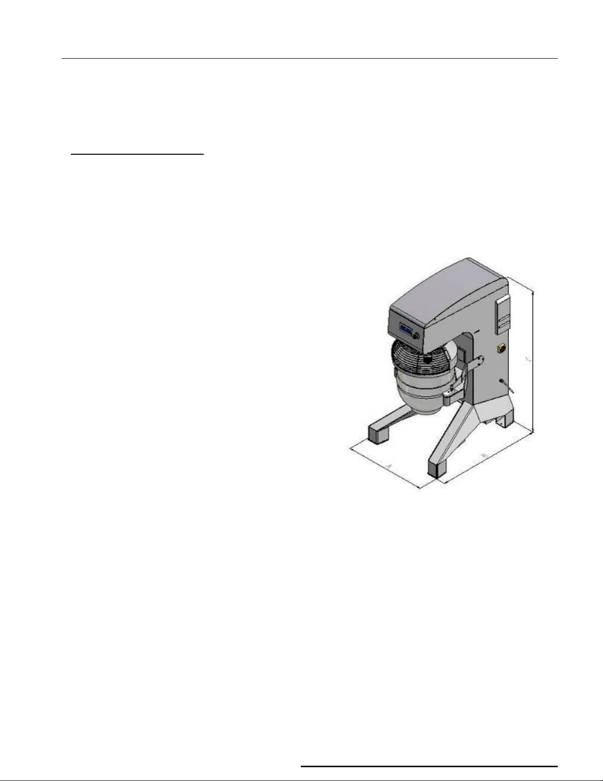
4.1.- OVERALL DIMENSIONS
Illustration 2 shows the unit’s overall dimensions.
BTF080
BTF100
BTF120
BTF140
A
[835mm]
CHAPTER 4
B
[1110 mm]
C
[1600 mm]
Page
Page 8
BTF080/ BTF100/ BTF120/ BTF140-E1R2
7
4.2.- TECHNICAL SPECIFICATIONS
• Structure built in AISI304 stainless steel.
• Accessories built in AISI304 stainless steel.
• Transmission by belts.
• Gradual linear change of speed.
• Electric lift and descent of the bowl (when applicable).
• Unit’s electronic control.
• Unit’s surfaces are completely smooth. This enables the complete cleaning of the machine.
• Wheels for easy transportation.
• Performances.
Model BTF080 BTF100 BTF120 BTF140
Power (KW)
Frequency
Voltage
Amperage
Electrical NEMA code configuration
Electrical connection
Maximum bowl capacity (liters)
3kw 3kw 3,7kw 3,7kw
60Hz 60Hz 60Hz 60Hz
208-240V 208-240V 208-240V 208-240V
17 17 20 20
L15-30P L15-30P L15-30P L15-30P
3PH+Gnd 3PH+Gnd 3PH+Gnd 3PH+Gnd
80 100 120 140
Maximum capacity (kg dough with a
16kg 20kg 24kg 28kg
minimum of 50% water)
4.3.- ELECTRICAL INSTALLATION
DOYON has developed the electrical system complying with present regulations, especially with North
American standards UL763, CSA 22.2 no195 NSF-8 and European normative EN 60204-1: ”Machinery
Security – Machines’ electrical equipment – Part 1: General Applications”.
Also conform to IP45 standards
To increase users’ safety, it is possible to connect a second earth cable. The connection point is identified
with the following symbol:
Page
Page 9

BTF080/ BTF100/ BTF120/ BTF140-E1R2
8
4.4.- SAFETY SYSTEM
The unit’s dangerous area is where tools work. Nevertheless, the user is not exposed to the risks because of
the solutions adopted to avoid injuries. There is a safety grid that has to be closed at all time during
operations.
When this safety grid is opened, the tools stop their motion.
During the maintenance process, you must open the covers which are usually screwed. The operator must be
very careful when moving parts of the machine.
The machine’s external general protection rate is IP20: there is no access to moving parts without removing
protections and covers with a key.
4.5.- CONTROL SYSTEM
The machine has a technologically developed system to control its functions. The electrical panel has failure
detection and phase sequence relay, an automaton, change of speed and other components to through-
connect and manage the system.
4.6.- EMERGENCY STOP
The machine has an emergency stop which is a red mushroom-type push button, illustration 6, according to
the present directives.
Illustration 6
4.7.- NOISE EMISSION
The use of special building techniques keeps an A-weighted average sound pressure level, under 70dB,
according to directive 98/37/CE and to normative ISO 3744. “Acoustic: Determination of sound power levels
sources using sound pressure. Engineering method in an essentially free field over a reflecting plane.”
Page
Page 10
BTF080/ BTF100/ BTF120/ BTF140-E1R2
9
CHAPTER 5
SHIPPING, POSITIONING AND ELECTRICAL CONNECTIONS
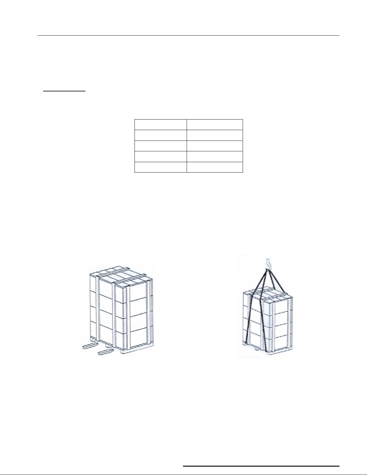
5.1.- SHIPPING
The machine’s weight is indicated on the following table.
.
Model Weight [kg]
BTF080
BTF100
BTF120
BTF140
The machine can be lifted, as seen on Illustration 7, with elevators, cables, ropes or hooks. These tools have
to be perfectly dimensioned to withstand the machine’s weight. The unit has to be moved with its wheels
blocked.
During manual moving, it is possible that the machine could slide more than expected or to another direction
because of the wheels.
550
550
590
590
Page
Page 11

BTF080/ BTF100/ BTF120/ BTF140-E1R2
0
BTF080/ BTF100/ BTF120/ BTF140
5.2.- POSITIONING
Illustration 7
The faulty installation of the machine may cause material and personal damage. In this case, the
manufacturer cannot be considered responsible.
The ground surface where the machine will be positioned has to be perfectly rigid and firm and allow the
machine to be balanced, avoiding it to fall during operation.
Page 1
Page 12

BTF080/ BTF100/ BTF120/ BTF140-E1R2
5.3.- ELECTRICAL CONNECTIONS
Make sure all electrical wall outlet of the building have the same voltage and power than described on the
machine’s registration plate (chapter 1).
The outlet should be near the machine.
Avoid connecting more than one machine on the same power connection.
The machine must receive power by an electrical line with ground point connection.
5.3.1.- CAUTIONS
WARNING: WHEN YOU USE ELECTRIC TOOLS, ALWAYS PROCEED WITH CAUTION TO REDUCE FIRE
RISKS, ELECTRIC SHOCKS AND PERSONAL DAMAGE. IN ANY CASE, ONLY TRAINED PERSONNEL
SHOULD HAVE ACCESS TO THE MACHINE’S ELECTRIC SYSTEM AND THEY SHOULD ALWAYS
FOLLOW THESE RULES:
1. Stop the machine.
2. Disconnect the electrical current with the master switch.
3. Pull the plug out from the electrical socket.
4. Do all necessary maintenance or repairing operations.
5. Make sure that the machine is in perfect condition to operate.
6. At the end, plug in the machine to the electrical grid again.
7. Connect the electrical current at the master switch.
Never disconnect or modify the machine’s safety systems.
Page 11
Page 13

BTF080/ BTF100/ BTF120/ BTF140-E1R2
2
CHAPTER 6
PLANETARY MIXER WORKING OPERATION
6.1.- PLACING THE INGREDIENTS
• Placing the ingredients is a very important step. The machine’s performance may depend on how
they are placed. They must be put in a way that does not force the machine’s components.
• Warning: during assembly and when taking down the mixer, tools and grid can present a risk:
superior limbs (hands) may be caught.
6.2. - WORKING OPERATION
• After you turn on the main switch, a screen will appear with the commercial brand.
The screen will disappear after a few seconds.
The next screen to appear will be the manual work screen.
• Place the ingredients.
• Put the trolley with the bowl on the machine’s arm.
• Install the tool as seen on illustration 8.
Page 1
Page 14

BTF080/ BTF100/ BTF120/ BTF140-E1R2
BTF080/ BTF100/ BTF120/ BTF140
Illustration 8
• The tools should not be installed if the bowl is not correctly placed on the machine. That would be
considered faulty and irrational use of the machine.
• Select a function on the display (speed should suit the product, in order to avoid the risk of forming
excessive dust).
• You may choose to operate with a program in manual or automatic mode.
• If you choose the automatic mode, the machine will stop at the end of the programmed time.
• If you choose manual mode, it is necessary to change specifications or to stop manually the machine.
Follow these steps:
• Open the safety grid.
• If you wish to interrupt the working operation, press “PAUSE” on the display.
• If you wish to end the working operation, press “STOP” on the display.
• For safety reasons, opening the grid has the same effect as pressing “PAUSE”, the machine stops all
movements.
• After closing the grid, it is necessary to choose the desired option on the display.
• This machine is equipped with an avant-garde technology digital control panel. A touch screen which may
be used by the simple touch of a finger. The use of hard or sharp objects can damage the screen.
• After switching the main switch on, the display shows the main options, which are:
Page 13
Page 15

BTF080/ BTF100/ BTF120/ BTF140-E1R2
4
Manual Mode – Screen Functions
A – State: off
Button to access the automatic screen. (see section Automatic Mode “D”).
c
Display of time visualisation, format “minutes : seconds”, increase in seconds, regulation every 30
d
seconds.
Display of speed scale, increase of 1 unity, regulation from “01” to “20”.
e
f Button to access the rise speed showed in e.
g Button to access the down speed showed in e.
h Button to access the time up showed in d.
i Button to access the time down showed in d.
Button to access the rising of the bowl’s arm (when applicable).
j
Button to access the descent of the bowl’s arm (when applicable).
k
cb
cc
cd
Button to access the function “pause” in work.
Button to access the function “start” of work with the time defined in d and the speed in e.
Space reserved for the identification logo.
Page 1
Page 16

5
B – State: in function
Inactive button.
c
If d is in “0” (zero) on start, the time showed during the work is ascending and is incremented until
d
the machine stops or it will automatically stop when 99 minutes and 99 seconds in d is reached.
If d is in “0” (zero) on start, the time showed during the work is decreasing and will be incremented.
The machine stops automatically when it reaches time “0” (zero) ind.
BTF080/ BTF100/ BTF120/ BTF140-E1R2
e
f
g
h
i
j
k
cb
cc
If d is in work, it will be ascending and adjusted to a superior value, it automatically begins to
decrease. In the same way, it can happen in the inverse situation, if d is decreasing and is
adjusted to an inferior value, it automatically starts to grow.
Display with the function defined in “A”.
Can be changed during the work.
Button to access the function defined in “A”.
Button to access the function defined in “A”.
Button to access the function defined in “A”.
Button to access the function defined in “A”.
Button to access the rising of the bowl’s arm (when applicable).
Button to access the descent of the bowl’s arm (when applicable).
Button to access the function “pause” in work. It maintains the time and velocities unchanged.
To restart the work, press “C”cb.
Button to access the function “stop” in work.
It stops the work and puts to zero the time in course in d.
This button appears automatically after the machine initiates the work.
cd
Space reserved with function defined in “A”.
Page 1
Page 17

6
C – State: Pause
Inactive button.
c
Display with constant value.
d
Display with function defined in “A”.
e
Button to access the function defined in “A”.
f
Button to access the function defined in “A”.
g
BTF080/ BTF100/ BTF120/ BTF140-E1R2
Button to access the function defined in “A”.
h
Button to access the function defined in “A”.
i
Button to access the rising of the bowl’s arm (when applicable).
j
Button to access the descent of the bowl’s arm (when applicable).
k
cb
cc
Button to access the function continues the work considering the value of “B”d.
Button to access the function “stop” in work.
It stops the work and puts to zero the time in course in d.
This button appears automatically after the machine initiates the work.
Automatic mode – Screen Functions
D – State: programming
Button to access the manual screen. (see Manual Mode “A”).
c
List of selection of programs to be executed. If any line is pressed, the screen automatically
d
changes to the automatic mode (see “E”).
Page 1
Page 18

BTF080/ BTF100/ BTF120/ BTF140-E1R2
7
List of program names
e
To edit each name, press the program wanted to go to the next screen.
The white area shows the text written.
Available buttons from “A” to “Z”.
Button “CLR” moves from the screen without saving and turns back to the screen “D”.
Button “ENT” saves and turns back automatically to the screen “D”.
List of the first speed to be executed.
f
To edit each speed, press the program wanted to go to the next screen.
The white area shows the numbers written.
Available buttons from “0” to “9”.
Button “ ” moves on the screen without saving and turns back to screen “D”.
Button “OK” saves and turns back automatically to screen “D”.
List of the second speed to be executed.
g
To edit each speed, press the program wanted to go to the next screen.
The white area shows the numbers written.
Available buttons from “0” to “9”.
Button “ ” moves on the screen without saving and turns back to screen “D”.
Button “OK” saves and turns back automatically to screen “D”.
List of the time of first speed to be executed.
h
To edit each time, press the program wanted to go to next screen.
Page 1
Page 19

BTF080/ BTF100/ BTF120/ BTF140-E1R2
8
The white area shows the numbers written.
Available buttons from “0” to “9”.
Button “ ” moves on the screen without saving and turns back to screen “D”.
Button “OK” saves and turns back automatically to screen “D”.
List of the time of second speed to be executed.
i
To edit each time, press the program wanted to go to next screen.
The white area shows the numbers written.
Available buttons from “0” to “9”.
Button “ ” moves on the screen without saving and it turns back to the screen “D”.
Button “OK” saves and turns back automatically to screen “D”.
Button to access the languages screen (see screen “K”).
j
cc
cd
E – State: off
(Available to start in first speed)
Button to access the screen of programs selection (see screen “D”).
Space reserved for the identification logo.
(Available to start in first speed)
(Available to start in second speed)
Page 1
Page 20

BTF080/ BTF100/ BTF120/ BTF140-E1R2
9
Button to access the programming screen (see screen “D”).
c
Display of visualisation of the time. Total of cg and ch .
d
Display with the function defined in “A”.
e
Button to access the function defined in “A”.
f
Button to access the function defined in “A”.
g
Button to access the function defined in “A”.
h
i
j
k
cb
cc
cd
ce
cf
cg
ch
Button to access the function defined in “A”.
Button to access the function defined in “A”.
Button to access the function defined in “A”.
Button to access the function “pause” .
Button to access the function “start” in work with the time defined in d and the speed defined in ce .
Space reserved for the identification logo.
First speed to be executed.
Second speed to be executed.
Time in the first speed.
Time in the second speed.
Page 1
Page 21

BTF080/ BTF100/ BTF120/ BTF140-E1R2
0
F – State: in function (first speed)
(first speed)
(second speed)
The frame shows the speed and time of the first and second speed. This allows the possibility of
changing the programmed values, i.e., if the frame is in speed 1 and time 1, use the buttons
f,g,
h, and i to change the values. To change the frame to speed 2 and time 2, press on top of speed
2 and time 2. It’s not possible for the machine to function in speed 2 and change the data of speed
1.
Inactive button.
c
Display of visualisation of time.
d
The time shown during the work is decreasing. The machine automatically stops when it reaches
time “0” (zero).
Display with the function defined in “A”.
e
Button to access the function defined in “A”.
f
Button to access the function defined in “A”.
g
Page 2
Page 22

BTF080/ BTF100/ BTF120/ BTF140-E1R2
Button to access the function defined in “A”.
h
Button to access the function defined in “A”.
i
Button to access the rising of the bowl’s arm. (when applicable).
j
Button to access the descent of the bowl’s arm (when applicable).
k
cb
cc
cd
ce
cf
cg
ch
G – State: in pause
Button to access the function “pause”. It maintains the time and velocities unaltered.
To restart the work, press “G” cb or “J” cb.
Button to access the function “Stop” .
Stops the machine and puts in state “E” d.
This button appears automatically after initiating the work.
Space reserved for the identification logo.
First speed.
Second speed.
Time of work in the first speed.
Time of work in the second speed.
(in first speed)
(in second speed)
Page 21
Page 23

BTF080/ BTF100/ BTF120/ BTF140-E1R2
2
Inactive button.
c
Display with constant value.
d
Button to access the function defined in “A”..
f
Button to access the function defined in “A”.
g
Button to access the function defined in “A”.
h
Button to access the function defined in “A”.
i
Button to access the rising of the bowl’s arm (when applicable).
j
Button to access the descent of the bowl’s arm (when applicable).
k
cb
cc
cd
ce
cf
cg
ch
Button to access the function “pause”. It maintains the time and velocities unaltered.
Button to access the function “stop”.
Stops the machine and puts in state “E” d.
This button appears automatically after initiating the work.
Space reserved for the identification logo.
First speed.
Second speed.
Time of work in first speed.
Time of work in second speed.
K – Language selection
After the selection of buttons d, e, f, g or h, the screen shows the selected language.
Button to access the automatic mode.
c
Button to select the Portuguese language.
d
Button to select the English language.
e
Button to select the French language.
f
Page 2
Page 24

BTF080/ BTF100/ BTF120/ BTF140-E1R2
Button to select the Spanish language.
g
Button to select the German language.
h
Button to access the instructions screen “L”.
i
Machine model
j
Serial number machine
k
Display of visualisation of the machine’s software version.
cb
L – How to use the equipment
Button to access the screen “K”.
c
Button to access the maintenance screen “M” (use password: “6996”).
d
Brief text explaining how to work the unit.
e
M – Other products (1/2)
Button to access the screen “L”.
c
Button to access the maintenance screen “N”.
d
Brief text with the list of other products.
e
Page 23
Page 25

4
N - Other products (2/2)
Button to access the screen “M”.
c
Button to access the maintenance screen “O”.
d
Brief text with the list of other products.
e
O – In and out
BTF080/ BTF100/ BTF120/ BTF140-E1R2
c
d
f
g
h
i
j
k
cb
cc
Screen to consult information on the inputs and outputs of the machine’s automaton.
“ON” represents active function.
“OFF” represents non-active function.
Button to access screen “N”.
Button to access screen “P”.
Display to visualise the state of the safety guard.
Display to visualise the state of the booster thermal relay.
Display to visualise the state of the emergency button.
Display to visualise the state of the bowl’s arm when up.
Display to visualise the state of the bowl’s arm when down.
Display to visualise the state of “RUN” of the booster.
Display to visualise the state of the output of the automaton when elevating the bowl.
Display to visualise the state of the output of the automaton when descending the bowl.
Page 2
Page 26

5
cd
BTF080/ BTF100/ BTF120/ BTF140-E1R2
Not used.
ce
cf
cg
ch
Button to introduce the machine’s model (for example “BTF”). Press button and enter the model.
Button to introduce the machine’s capacity (for example “080”). Press button and enter the model.
Button to introduce the machine’s specificity (for example “M”). Press button and enter the model.
Button to introduce the machine’s serial number (for example “9999”). Press button and enter the
model.
P - Counters
Access the menu were it’s possible to consult information related to the work and information on the
machine’s thermal protection.
Button to access the screen “O”.
c
Display to visualise the total time “RUN” of the booster.
d
Display to visualise the partial time of “RUN” of the booster.
e
Button to access screen “Q” .
f
Display to visualise the total time of “STANBY” of the booster.
g
Display to visualise the partial time of “STANBY” of the booster.
h
Display to visualise the number of times the thermal booster stops.
i
Display to visualise the partial number of times that the thermal booster stops.
j
Page 2
Page 27

BTF080/ BTF100/ BTF120/ BTF140-E1R2
6
Q – Erase partial counters
By pressing any of the options, it returns automatically to the screen “P”.
Button to accept the reset of the partial counters.
c
Button to reject the reset the partial counters.
d
R – Messages to the user
This machine, due to its particularity of functioning, needs all electrical phases to be connected in
R1
order to work, and for the phases to be in the correct sequence. If one of those conditions isn’t
verified, the screen shows a message.
It is necessary for the electric power supply to the defined in machine plate. If necessary, invert the
two phases in the machine’s plug.
This message appears when putting the machine to work and the bowl is in low position.
R2
By pressing the up arrow, the bowl rises. When it reaches the top, the message disappears and the
screen changes automatically to screen “A” or “E”, according to the work requested.
Page 2
Page 28

BTF080/ BTF100/ BTF120/ BTF140-E1R2
7
This message appears when the machine is malfunctioning, by undue use or a mechanical
R3
problem. It’s necessary to disconnect the machine with the main switch and wait a few minutes to
allow the booster to restart. If the message occurs frequently, request an intervention from the
authorised technical assistance.
This message appears when the emergency button is on. It’s not possible to put the tools in function
R4
with this message on screen.
This message appears when the safety guard is on. It’s not possible to put the tools in function with
R5
this message on screen.
Page 2
Page 29

BTF080/ BTF100/ BTF120/ BTF140-E1R2
8
CHAPTER 7
MAINTENANCE
WARNING: BEFORE EVERY CLEANING OR MAINTENANCE OPERATION, CUT OFF THE POWER BY
THE MAIN SWITCH AND DISCONNECT THE ELECTRIC PLUG FROM THE CURRENT TAP.
When doing potentially dangerous operations such as refinements, maintenance, dismantling, electric,
mechanical or pneumatic component replacements, etc, the user must be sure that the plug is pulled out.
During and after any operation in which one or more security systems have been dismantled, it is forbidden to
put the machine into use until these protections are correctly installed again.
CAUTION: Internal mechanical components can involve some risks. Use appropriate protection gloves to
handle them.
7.1.- WHEN THE MACHINE IS NEW
When the machine is new, it is strongly advised to test it with ingredients that will not be used for human
consumption before starting production.
This way, any waste caused by shipping, installation and tests will be removed.
7.2.- EVERY DAY
7.2.1.- CLEANING
The machine must be cleaned every day, especially the parts that are in contact with the product.
Do not use knives, striking surfaces or metallic and hard objects while cleaning the machine, it could damage
it. Instead, you should use a vacuum cleaner, smooth clothes or sponges.
Do not use toxic products, solvents, irritants, abrasives or any products that could damage the surface or
contaminate the product.
This period may be adjusted depending on the machine’s use frequency.
7.3.- EVERY SIX MONTHS
7.3.1.- CHECK THE BELTS
Belt stretching should be done by authorised and trained personnel. In order to reach the zone where the
upper cover is, use a step-ladder which complies with the safety standards, or any other lifting equipment
complying with the standards and legislation.
Page 2
Page 30

BTF080/ BTF100/ BTF120/ BTF140-E1R2
9
If necessary, proceed as follows to stretch the belts:
• Disconnect the electrical current at the master switch and pull the plug out from the electrical socket.
• Unbolt the screw of the upper cover.
• Loosen the screws of the motor’s support.
• Turn the stretcher screw of the motor located at the machine’s interior until the belts are correctly
stretched.
• Tighten again the screws of the motor’s support.
• Close the command cover and bolt the screw of the cover.
Depending on the frequency of use and the machine’s efforts, this period could change. The relation is
inversely proportional: the more frequent is the use and the machine’s efforts, the shorter is the time between
each checking.
7.3.2.- CHECK THE STATE OF THE BOWL’S FIXING SYSTEM
The installation of the bowl’s fixing device must be done by authorised and trained personnel.
The installation of the bowl’s fixing device (illustration 9) must be done as follows:
Check which screw needs to be fitted;
Unbolt the counter-nut;
Fit the screw;
Bolt the counter-nut.
BTF080/BTF100/BTF120/BTF140
Illustration 9
Page 2
Page 31

BTF080/ BTF100/ BTF120/ BTF140-E1R2
0
CHAPTER 8
SAFETY INSTRUCTIONS
8.1.- SAFETY INSTRUCTIONS
• This machine was designed to be used only by qualified and trained personnel for the production of
dough, creams, pastries and confectioneries. The manufacturer should never be considered responsible
for any damage on people or objects caused by its faulty, irrational or misuse.
• After being unloaded, check the machine’s integrity.
• Before each cleaning or maintenance operation, turn it off with the master switch and remove the plug
from the electrical grid.
• Do not dismantle any protection system from the machine.
• If any cover is damaged, do not continue using the machine. Request the intervention of the authorised
technical assistance.
• According to each usage, it is possible that some of the product gets out of the bowl. Depending on what
product is being used, there could be a major or minor risk of eye contact. If necessary, use individual
protection equipment. In case of contact, proceed as described in the technical/ safety information form of
the product.
• Never switch the machine on if any protection system is dismantled.
• In case of breakdown or faulty operation, turn the machine off and don’t try to fix it. Please call a
specialist. Repairs should be done by authorised support agents and should use original components.
Ignoring this instruction may involve security problems or low performances of the machine.
• The instruction manual is part of the machine and should be preserved during the entire machine’s use.
8.2.- SPECIAL CARE
8.2.1.- WITH TOOLS
One of the machine’s potentially dangerous area is where tools work.
The user doesn’t need to access directly this zone because the grid is closed during normal operation.
8.2.2.- WITH BELTS
One of the machine’s most dangerous site is the area where the transmission belts are located.
The user doesn’t need to access directly this zone because there is a bolted cover on during normal
operation.
Page 3
Page 32

BTF080/ BTF100/ BTF120/ BTF140-E1R2
8.2.3.- WITH ELECTRIC CURRENT
The electrical system complies with the security European legislation, particularly with the Directives
98/37/CE, 93/68/CEE and 89/336/CEE and has been tested according to the International Normative EN
60204-1. Also has been tested according to North American standards UL763, CSA22.2 no 195 and NSF-8,
also has been tested to meet IP54 Normative.
When you use electric tools, always be cautious to reduce fire risks, electric shocks and personal damage.
Only trained personnel should have access to the machine’s electric system, and should always follow these
rules:
1. Stop the machine.
2. Disconnect the electrical current with the master switch.
3. Remove the plug from the electrical socket.
4. Do all necessary maintenance or repairing operations.
5. At the end, plug the machine to the electrical grid again.
8.2.4.- WITH HYGIENE
All material in contact with the dough is inoffensive and not toxic (stainless steel AISI 304).
8.3. – PRODUCT LIFE CYCLE
During the product life cycle, at any phase, the manufacturer is responsible for whatever is related to any
piece, component or material. The product life cycle management must always be done by the manufacturer,
having this responsibility only in case of being properly informed of the situation.
This management covers the possible repair and reuse of any piece, component or material. However, if this
is not possible, the situation should be taken by suitable waste managers whose objective is recycling. This is
why the manufacturer places on the market units with extremely high recycling rates and high technology.
The different norms of each country must be complied and each case must be considered individually.
For European Union Countries, this equipment has the recycling symbol illustrated below. This means all
waste must be separated by category and be placed at a suitable recycling waste container, never in
domestic waste containers. The environment surrounding us and the one of our future generations will profit
from this attitude.
Illustration 10
Page 31
 Loading...