

Page 1

DOYON PLANETARY MIXER BTF
007/010/020/040/040H/060/060H
TABLE OF CONTENTS
TO GET THE BEST PERFORMANCE OF YOUR MACHINE, PLEASE READ THIS MANUAL.
CHAPTER 1 – RECEPTION OF THE MERCHANDISE . . . . . . . . . . . . . . . . . . . . . . . 2
NAMEPLATE . . . . . . . . . . . . . . . . . . . . . . . . . . . . . . . . . . . . . . . . . . . . 2
CHAPTER 2 - GENERAL DESCRIPTION . . . . . . . . . . . . . . . . . . . . . . . . . . . . . . . . . 3
CHAPTER 3 - MIXER USE
3.1. - General description . . . . . . . . . . . . . . . . . . . . . . . . . . . . . . . . . . . . . 4
3.2. - Machine characteristics . . . . . . . . . . . . . . . . . . . . . . . . . . . . . . . . . . 4
3.3. - Improper use of the machine . . . . . . . . . . . . . . . . . . . . . . . . . . . . . . 4
CHAPTER 4 – TECHNICAL DATA
4.1. - General information . . . . . . . . . . . . . . . . . . . . . . . . . . . . . . . . . . . . 5
4.2. - Technical characteristics . . . . . . . . . . . . . . . . . . . . . . . . . . . . . . . . 6
4.3. - Electric motor . . . . . . . . . . . . . . . . . . . . . . . . . . . . . . . . . . . . . . . . . 6
4.4. - Electric installation . . . . . . . . . . . . . . . . . . . . . . . . . . . . . . . . . . . . . 6
4.5. - Security system . . . . . . . . . . . . . . . . . . . . . . . . . . . . . . . . . . . . . . . 7
4.6. - Control panel . . . . . . . . . . . . . . . . . . . . . . . . . . . . . . . . . . . . . . . . . 9
CHAPTER 5 - ELECTRIC CONNECTION AND INSTALLATION
5.1. - Installation . . . . . . . . . . . . . . . . . . . . . . . . . . . . . . . . . . . . . . . . . . . . 10
5.2. - Electric connection . . . . . . . . . . . . . . . . . . . . . . . . . . . . . . . . . . . . . 11
CHAPTER 6 – MIXER OPERATION
6.1. - Tool’s settings . . . . . . . . . . . . . . . . . . . . . . . . . . . . . . . . . . . . . . . . . 12
6.2. - Bowl’s settings . . . . . . . . . . . . . . . . . . . . . . . . . . . . . . . . . . . . . . . . 14
6.3. - Working operation . . . . . . . . . . . . . . . . . . . . . . . . . . . . . . . . . . . . . . 15
6.3. – Hub attachment operation. . . . . . . . . . . . . . . . . . . . . . . . . . . . . . . . . 15
CHAPTER 7 - MAINTENANCE
7.1. - Machine’s cleaning . . . . . . . . . . . . . . . . . . . . . . . . . . . . . . . . . . . . . 16
7.2. - Control of belt’s stretching . . . . . . . . . . . . . . . . . . . . . . . . . . . . . . . 16
CHAPTER 8 – SAFETY INSTRUCTIONS
8.1. - Safety instructions . . . . . . . . . . . . . . . . . . . . . . . . . . . . . . . . . . . . . . 17
8.2. - Special precautions. . . . . . . . . . . . . . . . . . . . . . . . . . . . . . . . . . . . . . 17
ELECTRIC SCHEMATICS . . . . . . . . . . . . . . . . . . . . . . . . . . . . . . . . . . . . . . . . . . . . . . 19
(BTF007,BTF010,BTF020),(BTF040,BTF040H),(BTF060,BTF060H)
LIMITED WARRANTY . . . . . . . . . . . . . . . . . . . . . . . . . . . . . . . . . . . . . . . . . . . . . . . . . 22
BTF-A.DOC 1102
1
Page 2

CHAPTER 1
CAUTION
READ ALL INSTRUCTIONS
IMPORTANT
RECEPTION OF THE MERCHANDISE
Take care to verify that the received equipment is not damaged before signing the delivery
receipt. If a damage or a lost part is noticed, write it clearly on the receipt. If it is noticed after
the carrier has left, contact immediately the freight company in order that they do their
inspection.
We do not assume the responsibility for damages or losses that may occur during
transportation.
For your safety, this equipment has been verified by qualified technicians and carefully crated
before shipment. The freight company assumes full responsibility concerning the delivery in
good condition of the equipment in accepting to transport it.
NAMEPLATE
Each machine has a nameplate fixed on the machine, with the general characteristics of the
machine.
1. Serial number
2. Model
3. Date
4. Phase
5. Amperage
6. Voltage
7. Frequency
BTF-A.DOC 1102
2
Page 3

CHAPTER 2
GENERAL INFORMATION’S ABOUT THE MACHINE
The machine’s manual must always be kept close to the machine during its usage.
• Before switching on and using the machine, read this manual carefully, especially the
security chapter.
• This manual must be kept in a safe place and accessible to everyone that use the
machine.
The manufacturer is not responsible for the machines damages in the following
situations:
• Bad use of the machine.
• Problems with electric power.
• Non-authorized changes.
• Deficient upkeep.
• Use of unoriginal parts and products of the machines.
• Not following this manual.
• Repairs not made by authorized technicians.
BTF-A.DOC 1102
3
Page 4

CHAPTER 3
MIXER’S USE
3.1 - GENERAL DESCRIPTION
Doyon mixer are designed to be used by qualified people in the pastry and bakery’s
business.
3.2 - MACHINE CHARACTERISTICS
Ideal for all kinds of pastry creams, cakes, puff pastries, bread, pizza and doughnut dough
productions.
3.3- IMPROPER USE OF THE MACHINE
This machine was designed to produce dough and creams used in pastry and bakery
productions.
Using this machine for other purposes will be considered improper and dangerous.
The manufacturer is not responsible for any machine damages or personal injuries due to
improper use of the machine.
BTF-A.DOC 1102
4
Page 5
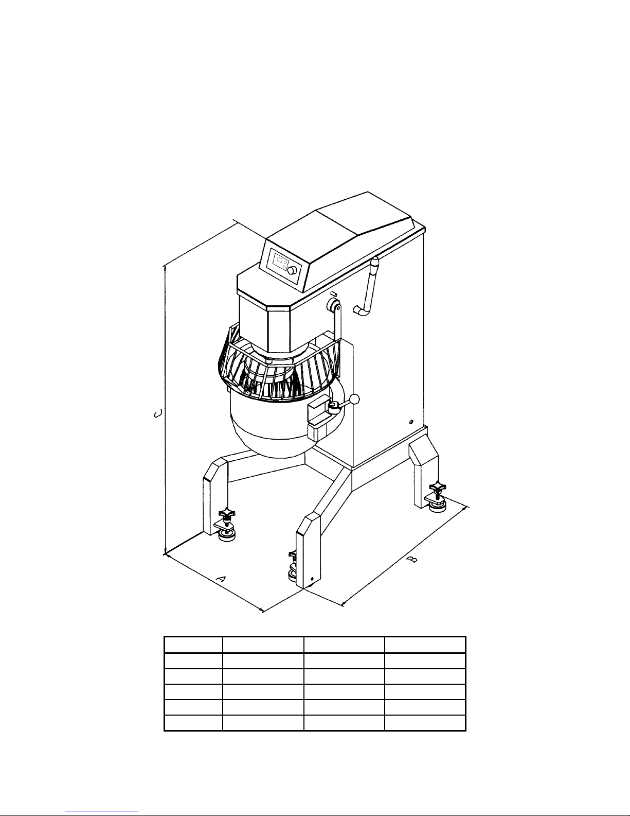
4.1. GENERAL DIMENSIONS
The fig. 4.1.1 shows the machine’s dimensions
CHAPTER 4
TECHNICAL DATA
Model A [inch/mm] B [inch/mm] C [inch/mm]
BTF007
BTF010
BTF020
BTF040
BTF060
BTF-A.DOC 1102
Fig 4.1.1
13 / 330 21 ¾ / 552 28 / 711
15 / 381 21 ½ / 546 32 ¾ / 832
16 / 406 26 ½ / 673 40 ½ / 1029
23 ½ / 597 37 ½ / 935 52 ½ / 1334
23 ½ / 597 37 ½ / 953 55 ¼ / 1403
5
Page 6

4.2- TECHNICAL CHARACTERISTICS
• Steel Body.
• Continuous electronic changing speed system.
• Simple speed adjustment to the required type of mixture.
• Electric control by buttons.
• Set of stainless steel mixing tools (hook, whip and beater).
• Bowl lifter activated by a manual lever (except BTF007, BTF010 and BTF020).
• Wheel-Mounted (except the BTF020, BTF010 and BTF007, with their dimensions,
they may be placed on a table).
• Synthetic paint that makes the machine’s surface completely smooth, and easier to
clean.
4.3 – ELECTRIC MOTOR
Model
Power [Hp]
Frequency [Hz]
Voltage
[Volt]
Phase
NEMA
Configuration
Speed variation type
Maximum Capacity
Qts
4.4- ELECTRIC INSTALLATION
Doyon’s machines have an electric installation in compliance with the American (ANSI/UL
std. 763),Canadian (CSA std. C22.2 no. 1335.2.14) and European rules.
BTF007 BTF010 BTF020 BTF040 BTF060
1/2 1/2 1 3 4
50/60 50/60 50/60 50/60 50/60
120
120
120 208-240 208-240
1 1 1 1 1 or ( 3 )
5-15P
5-15P
5-15P 6-15P 6-20P or (L15-20P)
Electronic Electronic Electronic Electronic Electronic
7
10
20 40 60
BTF-A.DOC 1102
6
Page 7
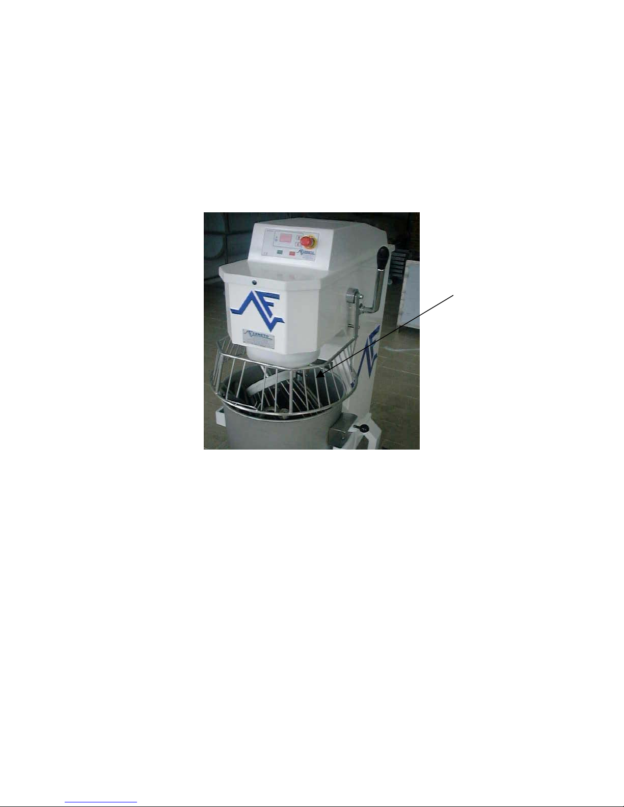
4.5 – SECURITY SYSTEM
The potentially most dangerous area of these machines is the mixing area caused by
rotating movements of the tools inside the bowl.
So, there is a safety guard that obstructs the entry in this area. This safety guard is
completely built in stainless steel and designed in a way to allow the user to watch the
dough (fig 4.5.1).
Security
Grid
Fig.4.5.1.
The machine can only begin its work if the safety guard is in the working position, that is
completely down. The machine has an electric protection system that does not allow the
machine to work if the safety guard is not completely down.
If you lift the safety guard, the machine will stop. To restart it, close the safety guard and
press the green button “Start”.
Before switching on the machine make sure the tools are well fixed.
It is forbidden to remove, modify or damage the safety guard of the machine.
BTF-A.DOC 1102
7
Page 8

If the safety guard is lifted and/or the bowl is down, as shown in fig.4.5.2, the machine will
not work. The machine only works when the safety guard and bowl are in working position,
as shown by the fig.4.5.3.
Fig. 4.5.2 Fig 4.5.3
BTF-A.DOC 1102
8
Page 9

4.6 CONTROL PANEL
Fig. 4.6.1 shows the control panel.
Up Speed Button
Down Speed Button
On indicator light
Speed display
Timer display Menu selector
Emergency Button
Start Button Stop Button
Down time button
Up time button
Start button: Press to start the machine.
Stop button: Press to stop the machine.
Emergency stop button: Press to stop the machine immediately. To restart, twist out the emergency button .
Up speed button: Press to increase the speed of the mixer..
Down speed button: Press to lower the speed of the mixer.
Timer: The timer has 8 menus; 7 menus that can be programmed with a timer and a speed. The other menu is
for manual mode. The time on the timer can be changed anytime during its countdown.
Manual mode: Press the menu selector repetitively until two horizontal bars appear (see picture above). The
mixer may be used with or without the timer. If you wish to use the timer in this mode, adjust the timer to the
desired time and start the machine or when the machine is in operation, set the timer to the desired time to
stop the machine at the end of the countdown.
Programmable mode: The factory preset times are 10, 20, 30, 40, 50, 60, 70.
To program a menu, select one of the 7 menus. Adjust the desired time with the “up and down time buttons”
and the speed with the “up and down speed buttons”. Press and hold the “menu selector” until the “on
indicator light” flashes once, this means that the program has been entered in the menu. It is possible to
program 7 menus. To select a programmed menu, press repetitively the “menu selector” until the desired
menu appears and press the green “start button” to start the mixer. To replace an existing menu by a new
menu, select the menu to be replaced and repeat procedure above.
BTF-A.DOC 1102
9
Page 10

CHAPTER 5
ELECTRIC CONNECTION AND INSTALLATION
5.1 INSTALLATION
THE MANUFACTURE IS NOT RESPONSIBLE FOR THE MATERIAL AND
PERSONAL DAMAGES THAT A WRONG INSTALLMENT MAY CAUSE.
The big mixers (BTF040 and BTF060) are wheel-mounted so you can move them easily.
BTF020 and BTF007 only have rubber levellings.
The floor surface where the machine will be in service must be solid, horizontally leveled,
in a way to prevent a possible instability.
The mixer doesn’t have to be fixed on the floor, just tighten up the anti-vibrate footing
supports.
Fig 5.1.1 to BTF040 and BTF060 and fig 5.1.2 to BTF020, BTF010 and BTF007.
Fig. 5.1.1 Fig 5.1.2
BTF-A.DOC 1102
10
Page 11

5.2- ELECTRIC INSTALLATION
Make sure that the plugs you have in the room have the same voltage and power presented
on the machine’s nameplate.
The electric plug must be as close as possible to the machine.
Avoid plugging more than one machine into the same electric plug. In case you need to
plug more than one machine in the same electric plug, make sure that it has the electric
capacity for it.
WARNING
Warning! Take all the precautions in a way to avoid dangers of fire, electrical shocks and
personal damages. Only qualified people are allowed to intervene in the electrical parts of
the machine, always follow these rules:
1. Stop the machine.
2. Switch off the power in the electric panel.
3. Take off the plug.
4. Do the necessary repairs or maintenance.
5. Plug the machine only at the end.
BTF-A.DOC 1102
11
Page 12

CHAPTER 6
MIXER OPERATION
6.1 – TOOL’S SETTING
BTF040/BTF060
Put the tools as shown in the fig. 6.1.1 and turn them as in fig. 6.1.2.
Fig. 6.1.1
Fig. 6.1.2
BTF-A.DOC 1102
12
Page 13

BTF007/BTF020
Put the tools as shown in fig. 6.1.3, lift the sleeve and place the tool in the groove.
Fig. 6.1.3
After placing the tool in the groove, pull down the sleeve to its original position.
BTF-A.DOC 1102
Fig. 6.1.4
13
Page 14

6.2. – BOWL SETTINGS
Put the bowl into the support, place “A” and “B”, fig.6.2.1, into the existent holes.
“A” “B”
Fig. 6.2.1
Lift the bowl with the lever to block the bowl, fig.6.2.2
Fig. 6.2.2
BTF-A.DOC 1102
14
Page 15

6.3 WORKING OPERATION
Turn the main switch to the position ( I ) ON and ( 0 ) OFF, fig 6.3.1.
Fig. 6.3.1
Twist out the emergency button and the display will light up. If the safety guard or the bowl is not
in the correct position, (OP) will appear on the speed display and (En) on the time display and the
machine will not start.
If the mixer does not work and you have (Er) on the “speed display” and (r o) on the time display,
turn off the main switch for 1 to 2 minutes then turn on the main switch and the machine will return
to its normal operation.
Press the start button ( I ) to start the machine and press stop button ( O ) to stop the machine.
6.4 – WORKING OPERATION FOR THE HUB ATTACHMENT ADAPTER
Vegetable slicer speed: 250 rpm.
Insert the vegetable slicer into the hub adapter and tight the screw on the hub adapter to prevent the
vegetable slicer from moving. To activate the vegetable slicer, turn on the main switch to the
position ( I ) (see fig.6.3.1), then press on the green button ON/OFF switch (see fig.6.4.1) to start
the slicer. To stop the vegetable slicer, press the red button ON/OFF switch (see fig.6.4.1) to stop
the slicer.
(ON/OFF switch) (Vegetable slicer)
(Hub attachment) (Hub adapter screw)
(Main switch) Fig.6.4.1 Fig.6.4.2
BTF-A.DOC 1102
15
Page 16

CHAPTER 7
MAINTENANCE
WARNING: BEFORE ANY OPERATIONS OF MAINTENANCE AND CLEANING,
SWITCH OFF THE MACHINE, TURN THE MAIN SWITCH OFF AND UNPLUG IT,
SOME OPERATIONS MIGHT BE DANGEROUS.
IF YOU NEED TO TAKE OFF SOME PROTECTIONS DURING THE OPERATIONS,
DO NOT START WORKING WITHOUT THEM.
7.1 MACHINE’S CLEANING
The machine must be cleaned every day, especially the areas that have contact with the
dough.
To clean the machine do not use knifes, sandpaper, metallic objects, hard brushes or any
tool that may damage its surface. You may use plastic tools or soft sponges.
Do not use toxic products, solvents, abrasive agents or any product that may damage the
surfaces or the dough’s composition.
Before switching the machine on, make sure that nothing has been forgotten on the
machine.
7.2 CONTROL OF BELTS STRETCHING
It’s necessary to control the belts stretching every 6 months in all transmissions. If the belts
are too loose, there will be loss in the machine’s power.
• Switch off the general switch and unplug the machine.
• Unscrew the cover of the machine.
• Lift the cover carefully in a way, to not disconnect any electric cable.
• Loosen the motor’s support screws.
• Turn the stretching motor support screw, placed in the backside of the machine, until
the belts are stretched.
• Screw again the motor’s support screw.
• Close the cover and screw it.
BTF-A.DOC 1102
16
Page 17

CHAPTER 8
SAFETY INSTRUCTIONS
8.1 – SAFETY INSTRUCTIONS
• The machine must be used only for the functions that it has been conceived for. Doyon
will not be responsible for the damages caused by an improper, bad or irrational use of
the machine .
• Before cleaning or doing maintenance, turn the main switch off and unplug it.
• Do not remove security parts of the machine.
• If the machine has inactive security units, do not turn it on.
• The work of the machine may be stopped by using the red stop switch.
• The control panel has low tension (24 v).
• If you detect any damages or bad function of the machine, inactive it immediately and
call for an authorized technician, otherwise it may cause irreversible damages in the
machine.
• The electric connection must follow the procedures presented in the installation chapter.
8.2 – SPECIAL PRECAUTIONS
8.2.1 CARES WITH THE TOOLS
The area inside the bowl is the working center of the machine, so it becomes the most
dangerous part of the machine.
The safety guard does not allow access to this area (point 3, fig.3). You may not remove it,
damage it or modify it.
BTF-A.DOC 1102
17
Page 18

8.2.2 CARES WITH TRACTION WHEELS
Danger, transmission must be protected with fixed protections. In order to have access to
them, you must respect the instructions of the manual.
8.2.3 ELECTRIC HAZARDS
The electric installation follows the Canadian, American and European security rules.
Nevertheless, when using electric tools respect the basic security rules in a way to avoid the
risk of fire, electric shocks, personal and material damages.
Only qualified people may access the parts that have electric current, which are obliged:
1. Stop the machine
2. Turn off the main switch
3. Unplug the machine.
4. Do the necessary operations
5. Plug the machine again.
8.2.4 HYGIENIC HAZARDS
All the materials that are in contact with the dough must be non toxic and inoffensive.
CAUTION
SAVE THESE INSTRUCTIONS
BTF-A.DOC 1102
18
Page 19

BTF-A.DOC 1102
19
Page 20

BTF-A.DOC 1102
20
Page 21

BTF-A.DOC 1102
21
Page 22

LIMITED WARRANTY
(Continental United States Of America And Canada Only)
Doyon Equipment Inc. guarantees to the original purchaser only that its product are free of
defects in material and workmanship, under normal use.
This warranty does not cover any light bulbs, thermostat calibration or defects due to or
resulting from handling, abuse, misuse, nor shall it extend to any unit from which the serial
number has been removed or altered, or modifications made by unauthorized service
personnel or damage by flood, fire or other acts of God. Nor will this warranty apply as
regards to the immersion element damaged by hard water.
The extent of the manufacturer’s obligation under this warranty shall be limited to the
replacement or repair of defective parts within the warranty period. The decision of the
acceptance of the warranty will be made by Doyon Equipment service department, which
decision will be final.
The purchaser is responsible for having the equipment properly installed, operated under
normal conditions with proper supervision and to perform periodic preventive maintenance.
If any parts are proven defective during the period of one year from date of purchase, Doyon
Equipment Inc. hereby guarantees to replace, without charge, F.O.B. Linière, Quebec, Canada,
such part or parts.
Doyon Equipment Inc. will pay the reasonable labor charges in connection with the
replacement parts occurring within one year from purchase date. Travel over 50 miles, holiday
or overtime charges are not covered. After one year from purchase date, all labor and
transportation charges in connection with replacement parts will be the purchaser’s
responsibility.
Doyon Equipment Inc. does hereby exclude and shall not be liable to purchaser for any
consequential or incidental damages including, but not limited to, damages to property,
damages for loss of use, loss of time, loss of profits or income, resulting from any breach or
warranty.
In no case, shall this warranty apply outside Canada and continental United States unless the
purchaser has a written agreement from Doyon Equipment Inc.
BTF-A.DOC 1102
22
 Loading...