

Doyon ARTISAN 1T series, ARTISAN 2T series, ARTISAN 3T series Owner's Manual
ÉQUIPEMENT DOYON INC.
1255, rue Principale
Linière, Qc, Canada G0M 1J0
Tel.: 1 (418) 685-3431
Canada: 1 (800) 463-1636
US: 1 (800) 463-4273
FAX: 1 (418) 685-3948
Internet: http://www.doyon.qc.ca
e-mail: doyon@doyon.qc.ca
ARTISAN OVEN
OWNER’S MANUAL
Product / Produit: ___________________________________
Serial number / Numéro de série: ______________________

DOYON ARTISAN OVEN
IMPORTANT SAFETY INSTRUCTIONS
READ AND SAVE THESE INSTRUCTIONS
TABLE OF CONTENTS
TO GET THE BEST PERFORMANCE OF YOUR MACHINE, READ
CAREFULLY THIS MANUAL.
1. SHIPPING...................................................................................................................... 3
2.RECEPTION OF THE MARCHANDISE ..................................................................3
3. INSTALLATION .......................................................................................................... 4
3.1. DISTANCES TO RESPECT ...................................................................................4
3.2. IN GENERAL .......................................................................................................... 5
3.3. TO THE ELECTRICIAN......................................................................................... 5
3.4. TO THE PLUMBER................................................................................................5
4. INTRODUCTION.........................................................................................................6
5. DESCRIPTION OF THE CONTROL........................................................................7
6. CONTROL OPERATION .........................................................................................10
6.1. TEMPERATURE ADJUSTMENT........................................................................ 10
6.2. SETTING POWER OF THE FRONT, TOP AND BOTTOM .............................. 10
6.3. SETTING TIMES .................................................................................................. 10
6.4. DISPLAY UNITS .................................................................................................. 10
7. WARNING MESSAGES............................................................................................11
7.1. OPENING MESSAGE........................................................................................... 11
7.2. COLD VAPOR MESSAGE................................................................................... 11
7.3. END OF COOKING .............................................................................................. 11
7.4. BREAKDOWN MESSAGES ................................................................................ 11
8. FIRST TIME HEATING THE OVEN...................................................................... 13
9. BAKING....................................................................................................................... 13
10. TROUBLESHOOTING............................................................................................ 14
11. OVEN MAINTENANCE AND CLEANING ......................................................... 15
COMPONENT PARTS ..................................................................................................17
2

CAUTION
READ ALL INSTRUCTIONS
The Artisan Ovens are manufactured with first quality material by experienced technicians.
Proper installation and maintenance will guarantee a reliable service for years to come. A
nameplate specifies the model number, serial number, voltage, amperage, frequency and
manufacturing date.
ATTENTION
DOYON is not responsible for damages to the property or the equipment
caused by personnel who is not certified by known organisations.
1. SHIPPING
For your safety, this equipment has been verified by qualified technicians and carefully crated
before shipment. The freight company assumes full responsibility concerning the delivery in
good condition of the equipment in accepting to transport it.
2.RECEPTION OF THE MERCHANDISE
Take care to verify that the received equipment is not damaged before signing the delivery
receipt. If a damage or a lost part is noticed, write it clearly on the receipt. If it is noticed after the
carrier has left, contact immediately the freight company in order that they do their inspection.
We do not assume the responsibility for damages or losses that may occur during transportation.
3

3. INSTALLATION
POWER FAILURE WARNING
WHEN YOU HAVE A POWER FAILURE, SHUT OFF THE OVEN
POWER SWITCH TO PROTECT THE ELECTRONIC COMPONENTS
WHEN THE POWER COMES BACK.
FOR YOUR SAFETY
DO NOT STORE OR USE GASOLINE OR OTHER FLAMMABLE
VAPORS AND LIQUIDS IN THE VICINITY OF THIS OR ANY
APPLIANCE.
WARNING
IMPROPER INSTALLATION, ADJUSTMENT, ALTERATION,
SERVICE OR MAINTENANCE CAN CAUSE PROPERTY DAMAGE,
INJURY OR DEATH. READ THE INSTALLATION, OPERATING AND
MAINTENANCE INSTRUCTIONS THOROUGHLY BEFORE
INSTALLING OR SERVICING THIS EQUIPMENT.
Installation and service must be done by specialised technicians. Contact a certified electrician
and plumber for set up.
The oven must be connected to the utility and electrically grounded in conformity to the effective
local regulations. If these are not established, the oven must be connected according to the
Canadian Electrical Code (CSA-C22.1-XX) or National Electrical Code (NFPA 70-XX). Refer to
last edition year for XX. Installation must also allow proper access for service (24 inches each
side and back).
The ovens must be installed with a proper ventilation according with the local building code.
3.1 DISTANCES TO RESPECT
A) Back of the oven: 1 inch (2.5 cm).
B) Top of the oven: a clearance of 6 inches (15.2 cm) to the ceiling must exist to permit
adequate venting and to give proper access to a technician.
C) Sides of the oven: do not install other than easily removable equipment for service and
maintenance (not closer than 1 inch (2.5 cm)).
D) It is recommended to have a certain length of water pipe, electric cable between oven and
wall to help gain access for service.
4

3.2 IN GENERAL
Take off the packaging material with care. Take off all the material used for packing and
accessories.
3.3 TO THE ELCTRICIAN
Electrical supply installation must be in accordance with the electrical rating on the nameplate.
Utility connections shall be designed to be disconnected without the use of tools or shall be of
sufficient length to permit the equipment to be moved for cleaning.
WARNING
The electrician must make sure that the supply cable does not come in contact with the oven
top which becomes hot.
3.4 TO THE PLUMBER
This equipment is to be installed to comply with the applicable federal, state or local plumbing
codes.
Utility connections shall be designed to be disconnected without the use of tools or shall be of
sufficient length to permit the equipment to be moved for cleaning.
Connect the steam system (1/2 NPT) to the water distribution network. We highly
recommend a water softener to eliminate scale and minerals in the water. A minimum
water pressure of 60 psi with a hardness reduction filtration system with a minimum flow
rate of 3 gpm is required. We suggest to use CUNO 3M #SF165 or equivalent. Connect the
drain of the oven (1/2 NPT) to the drain system of the building or install a recipient to
retrieve the surplus of hot water from the steam system.
5

4. INTRODUCTION
The Artisan’s control panel is used to independently determine the heat of: the top of the oven,
the sole (stone) and the front of the oven. The steam is regulated by using 2 timers: TIMER and
STEAM TIMER.
It also controls various maneuvers necessary for the operation of the oven such as the on-off oven
light, the on-off exhaust and INSTANT POWER REDUCER, enabling the steam generator.
The controller incorporates an ecomode (Saver) which ensures that the power consumption does
not exceed 50% of the total power without altering their behavior.
The control automatically performs a series of actions that are intended to simplify the cooking
process for the baker. The actions that the operator would have to do manually during a cooking
cycle such as start the cooking timer, steam injection, changing the temperature of cooking, etc.
are performed automatically by simply pressing the
cycle button .
The control panel displays an intuitive user friendly interface making it easy to navigate.
6
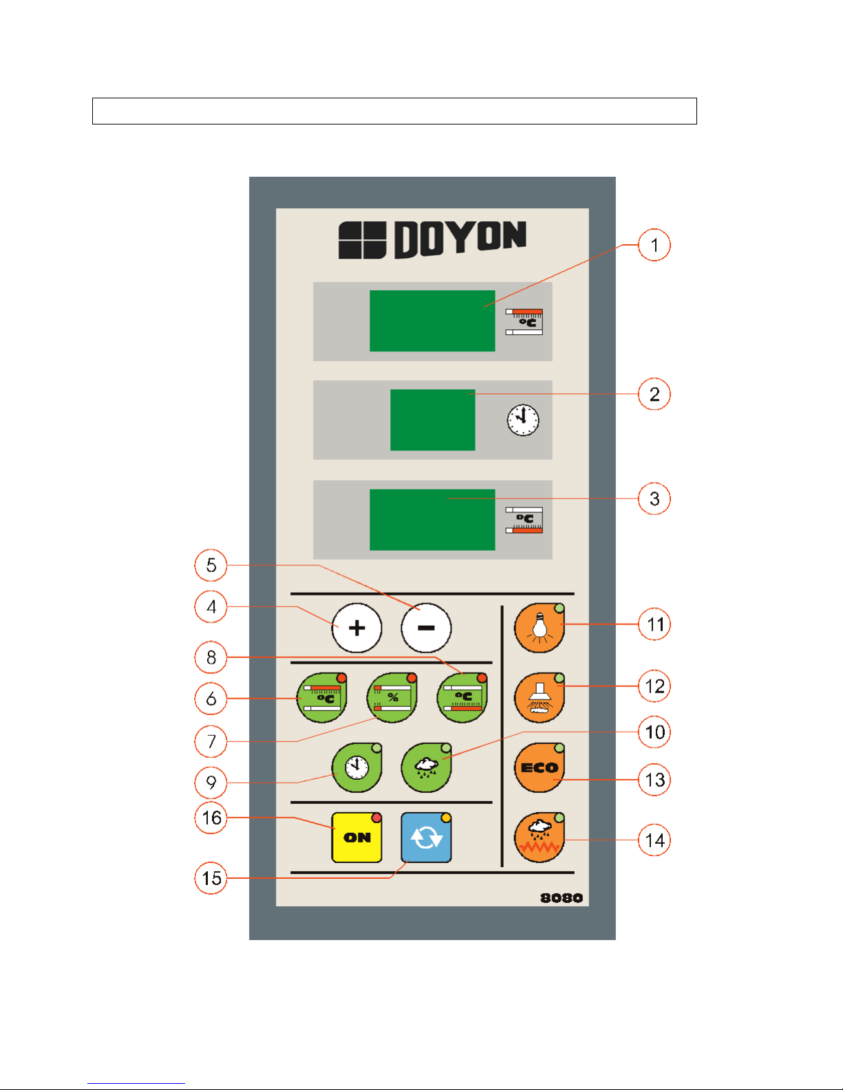
5. DESCRIPTION OF THE CONTROL PANEL
7

1) TOP TEMPERATURE
Displays the temperature of the TOP. It is also used in the parameter settings mode.
2) CLOCK
Displays the cooking timer. When the cooking timer is running, the display shows the
minutes remaining to complete the cooking time and a flashing light spot indicates that it
is counting time.
3) STONE TEMPERATURE
Displays the temperature of the sole (stone). It is also used in the mode parameter settings.
4) INCREASE KEY VALUES
Key used to increase the value of the parameter.
5) DECREASE KEY VALUES
Key used to decrease the value of the parameter.
6) TOP KEY
Pressing this button will display the desired temperature for the top. Edit with keys up or
down, and press the button again to save the setting and return to the actual temperature
display.
7) FRONT HEAT COMPENSATOR KEY
Pressing this button will display the desired % of heat compensation for the top-front of
the unit. By pressing the button again, it will display the % of heat compensation for the
sole (stone). Edit with keys up or down and press the button again to save the setting and
return to actual temperature display. We suggest that you keep the % level between 3%
and 5%.
8) SOLE (STONE) KEY
Pressing this button will display the desired temperature for the sole (stone). Edit with
keys up or down, and press the button again to save the setting and return to the actual
temperature display.
9) TIMER KEY
Pressing this button will allow you to program the cooking time. Edit with keys up or
down. Press the timer button to save and exit the editing.
If cooking is underway, pressing this key lets you change the time remaining. Press the
button to save and exit the editing.
8

10) STEAM INJECTION KEY
When steam is enabled and the steam button is pressed briefly, steam is injected with a
scheduled duration.While injecting, the pilot key will be on.
If the pilot light is flashing, it means that the oven temperature is not high enough to
permit steam generation.
11) LIGHT KEY
When you press this button, the oven light will turn on. The light stays on until you press
this key again, so that the light goes off. The pilot shows the status of operation of the
oven light: if the pilot is on, the oven light is on.
12) HOOD KEY
When you press this, the hood turns on. The fan stays on until you press this button again.
The pilot shows the status of operation of the hood, if the pilot is on, the fan is running. (If
the oven is equiped with the optional hood )
13) ECOMODE KEY
This key can activate / deactivate the ecomode. The pilot shows the status of the ecomode.
If the pilot is on, the ecomode is operating.
14) STEAM GENERATOR SYSTEM ON/OFF KEY
Pressing this key allows or disallows the heating of the steam generator.If you do not
allow the steam heating, the pilot key will be off.
15) START/STOP RECIPE KEY
Start or stop the cooking program. Pressing the control starts the cooking cycle, activating
the cooking timer and injecting steam. If you wish to terminate the cooking cycle, press
the key again.
16) ON/OFF KEY
This key is used to turn ON or OFF the oven. The control remains standby (standby) and
shows this situation by turning off all displays, except the pilot of the ON button remains
lit.
9

6. CONTROL OPERATION
6.1 TEMPERATURE ADJUSTMENT
Select the temperature for the TOP or SOLE by pressing the TOP or SOLE
button, the corresponding display and button will remain intermittent.
Select the desired temperature with the buttons or , and confirm by pressing
the intermittent button.
6.2 SETTING POWER OF FRONT HEAT COMPENSATOR
Select the power of the FRONT-TOP and FRONT-SOLE by pressing the button.
The first time you press it, the % of heat compensation of the FRONT-TOP will appear on
the display of the TOP.
Select the desired % of compensation with the buttons or , and confirm by
pressing the intermittent button.
Then the % of heat compensation of the FRONT-SOLE will appear. Adjust and confirm
by repeating the previous steps.
6.3 SETTING TIMES
Select the desired cooking time in minutes by briefly pressing the button. The
button and the clock display will remain intermittent, set the time if necessary and save
the value by pressing the key again.
6.4 SET DISPLAY UNITS
The user can also set whether the display is in degrees celcius (ºC) or degrees fahrenheit
(Fº).
In order to do so, you must press any of those two keys for 2 seconds. Select
the desired value, then press the button to save and exit the selection of units.
10

7. WARNING MESSAGES
7.1 OPENING MESSAGE
When plugging the oven in, some information on the type of the oven and other technical
parameters will appear during a few seconds. Those informations are not for the use of the
user.
7.2 COLD VAPOR MESSAGE
If there is a need for vapour, the button should be pressed until the pilot light is
turned on. At this time, the steam generator will heat until it reaches the temperature set
by the manufacturer.
When the steam button is intermittent, this means that the steam temperature is not
correct. When the pilot light goes off, it means that the cooking can start. When the
temperature is correct light goes out indicating that you can start cooking.
The user can see what is the steam temperature by pressing the button for 2
seconds. The steam temperature is shown on the upper display for 30 seconds.
7.3 END OF COOKING
When the cooking begins, the cooking timer will countdown each minute until it reaches
0. When the timer reaches 0, a warning indicating the end of the cooking time will appear.
The warning indicating the end of cooking is intermittent and will remain so for the
period of time. If the user presses any button during the warning, it will stop.
Once the cooking time has ended, and if the cooking cycle has not been interrupted by the
user, the cycle counter will continue counting the time that is added on to the cooking
time. The clock display will remain intermittent indicating this situation.
At 2,4,6,8,10 minutes, added to the cooking cycle, the panel sends out a warning with a
brief intermittent buzzer. At 10 minutes the cycle is automatically stopped.
7.4 BREAKDOWN MESSAGES
A breakdown produces a continuous warning in one of the displays, and activates the
alarm relay until the fault is acknowledged by pressing any key. At that moment the
warning relay is deactivated, and the message continues to show on the display until the
fault is repaired. Breakdowns disconnect all control outputs warning.
11
 Loading...