

Page 1

SPIRAL MIXER DOYON AEF 015/035/050/080/100/120
IMPORTANT SAFETY INSTRUCTIONS
SAVE THESE INSTRUCTIONS
DANGER
TO REDUCE THE RISK OF FIRE OR ELECTRIC SHOCK,
CAREFULLY FOLLOW THESE INSTRUCTIONS.
TABLE OF CONTENTS
TO GET THE BEST PERFORMANCE OF YOUR MACHINE, PLEASE READ
CAREFULLY THIS MANUAL.
CHAPTER 1 – RECEPTION OF THE MERCHANDISE. . . . . . . . . . . . . . . . . . . . . 2
NAMEPLATE . . . . . . . . . . . . . . . . . . . . . . . . . . . . . . . . . . . . . . . . . 2
CHAPTER 2 – GENERAL DESCRIPTION . . . . . . . . . . . . . . . . . . . . . . . . . . . . . . . 2
CHAPTER 3 - TECHNICAL DATA
3.1. – General description . . . . . . . . . . . . . . . . . . . . . . . . . . . . . . . 3
3.2. – Technical characteristics . . . . . . . . . . . . . . . . . . . . . . . . . . . . 4
3.3. – Electrical characteristics. . . . . . . . . . . . . . . . . . . . . . . . . . . . . 4
3.4. – Damage situations . . . . . . . . . . . . . . . . . . . . . . . . . . . . . . . . . 4
3.5. – Electric installation . . . . . . . . . . . . . . . . . . . . . . . . . . . . . . . . 4
3.6. – Security system . . . . . . . . . . . . . . . . . . . . . . . . . . . . . . . . . . . 6
3.7. – Control panel . . . . . . . . . . . . . . . . . . . . . . . . . . . . . . . . . . . . . 6
3.8. – Emergency stop. . . . . . . . . . . . . . . . . . . . . . . . . . . . . . . . . . . . 6
CHAPTER 4 – SPIRAL MIXER OPERATION
AEF 015
4.1. – Electric information . . . . . . . . . . . . . . . . . . . . . . . . . . . . . . . . . 9
4.2. – First start . . . . . . . . . . . . . . . . . . . . . . . . . . . . . . . . . . . . . . . . . 9
4.3. – Work start . . . . . . . . . . . . . . . . . . . . . . . . . . . . . . . . . . . . . . . . 10
4.4. – How to stop the spiral mixer. . . . . . . . . . . . . . . . . . . . . . . . . . 10
AEF 035/050/080/100/120
4.1. – General characteristics . . . . . . . . . . . . . . . . . . . . . . . . . . . . . . 11
4.2. – Electric information . . . . . . . . . . . . . . . . . . . . . . . . . . . . . . . . 11
4.3. – Start . . . . . . . . . . . . . . . . . . . . . . . . . . . . . . . . . . . . . . . . . . . . . 11
4.4. – Manual working process . . . . . . . . . . . . . . . . . . . . . . . . . . . . . 12
4.5. – Automatic working process . . . . . . . . . . . . . . . . . . . . . . . . . . 13
4.6. – Programming the automatic working time . . . . . . . . . . . . . . . 15
4.7. – How to stop the spiral mixer . . . . . . . . . . . . . . . . . . . . . . . . . 16
Page 2

CHAPTER 5 - MAINTENANCE
5.1. – When the machine is new . . . . . . . . . . . . . . . . . . . . . . . . . . . . 17
5.2. – Every day . . . . . . . . . . . . . . . . . . . . . . . . . . . . . . . . . . . . . . . . 17
5.3. – Every 6 months . . . . . . . . . . . . . . . . . . . . . . . . . . . . . . . . . . . . 18
CHAPTER 6 – SAFETY INSTRUCTIONS
6.1. – Safety instructions . . . . . . . . . . . . . . . . . . . . . . . . . . . . . . . . . . 19
6.2. – Hazards . . . . . . . . . . . . . . . . . . . . . . . . . . . . . . . . . . . . . . . . . . 19
ELECTRIC SCHEMATICS
AEF015. . . . . . . . . . . . . . . . . . . . . . . . . . . . . . . . . . . . . . . . . . . . . . . . 21
AEF 035/050/080/100/120 . . . . . . . . . . . . . . . . . . . . . . . . . . . . . . . . . 22
LIMITED WARRANTY
Warranty . . . . . . . . . . . . . . . . . . . . . . . . . . . . . . . . . . . . . . . . . . . . . . . 23
AEF-A.DOC 02/2003
1
Page 3

CHAPTER 1
IMPORTANT
RECEPTION OF THE MERCHANDISE
Take care to verify that the received equipment is not damaged before signing the delivery
receipt. If a damage or a lost part is noticed, write it clearly on the receipt. If it is noticed after
the carrier has left, contact immediately the freight company in order that they do their
inspection.
We do not assume the responsibility for damages or losses that may occur during transportation.
NAME PLATE
Each machine has a nameplate fixed on the machine, with the general characteristics of the
machine.
1. Serial number
2. Model
3. Date
4. Phase
5. Amperage
6. Volts
7. Frequency
CHAPTER 2
GENERAL DESCRIPTION
Doyon Spiral Mixers are designed to be used by qualified people in the Bakery production.
The particular shapes and speeds of the spirals and bowls allow you to have in a short period
of time, very smooth dough, even when small quantities of water are used. Our spiral mixers
are able to work with small quantities of flour (for instance, the mixer of 220 Lbs. of flour
may work with 11 Lbs. of flour).
It also has a very simple control panel, easy to work with. You may choose between the
automatic or manual mode (except AEF015), each mode come with two speeds.
Our spiral mixer is not only used in bakery and pastry productions but also in inks
productions, chemist’s shops, etc.
For your safety, this equipment has been verified by qualified technicians and carefully crated
before shipment. The freight company assumes full responsibility concerning the delivery in
good condition of the equipment in accepting to transport it.
AEF-A.DOC 02/2003
2
Page 4
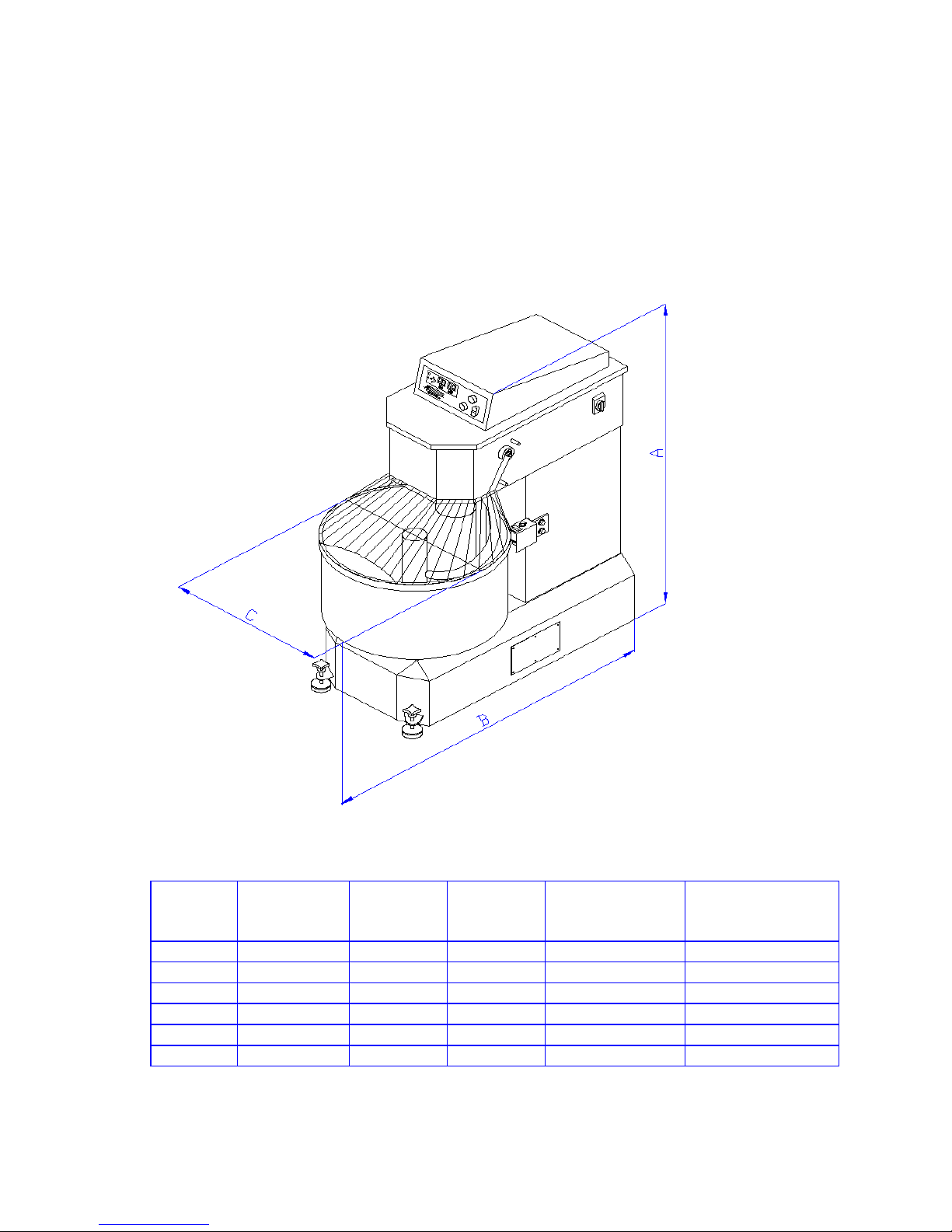
3.1 – GENERAL DESCRIPTION
CHAPTER 3
TECHNICAL DATA
Specifications of spiral mixers:
A
Model
AEF 015 38 ¾ "(98.5) 28 ¾"(73) 16"(40.5) 2-30 (1-15) 3-50 (1.5-25)
AEF 035 46 ¼ "(118.5) 41"(104) 21 ½"(54.5) 5-75 (2-35) 8-130 (3.5-60)
AEF 050 51"(129.5) 46"(117) 27"(68.5) 7-110 (3-50) 12-175 (5.5-80)
AEF 080 54"(137) 60"(152.4) 31"(75.5) 11-175 (5-80) 18-280 (8-125)
AEF 100 54"(137) 58"(147) 34"(86.5) 22-220 (10-100) 35-350 (16-160)
AEF 120 56"(142) 58"(147) 34"(86.5) 22-260 (10-120) 35-425 (16-190)
AEF-A.DOC 02/2003
Inch (cm)
Fig.1
B
Inch (cm)CInch (cm)
Flour Capacity
Lbs (kg)
Dough
Capacity
Lbs (kg)
3
Page 5

3.2. – TECHNICAL CHARACTERISTICS
• Steel body.
• Independent electric motors for stainless steel spiral and bowl (except AEF015).
• Belt driven transmission.
• Two speeds on stainless steel spiral.
• Two speeds on stainless steel bowl.
• Safety guard with micro switch.
• Manual and automatic digital control with 50 memories of desired working time (except
AEF015).
• Heavy-duty painting.
3.3 – ELECTRICAL CHARACTERISTICS
• The spiral mixers are 208-240 volts.
• Speed – 900 R.P.M. for 1st speed and 1800 R.P.M. for 2nd speed.
• Frequency – 60 Hz
• 208-240 volts
• 3 phases
• 4 wires (3 lines+gnd)
3.4 – THE MANUFACTURER IS NOT RESPONSIBLE FOR THE MACHINE’S
DAMAGES IN THE FOLLOWING SITUATIONS:
• Bad use of the machines.
• Using them out of the national laws.
• Problems with electric power.
• Non-authorised changes.
• Deficient upkeep.
• Use of unoriginal parts and products of the machines.
• Not following this manual.
• Repairs made by unauthorised technicians.
3.5 – ELECTRIC INSTALLATION
Doyon’s machines have an electric installation in compliance with the American (ANSI/UL
std. 763), Canadian (CSA std. C22.2 no. 1335.2.14) and European rules.
AEF-A.DOC 02/2003
4
Page 6
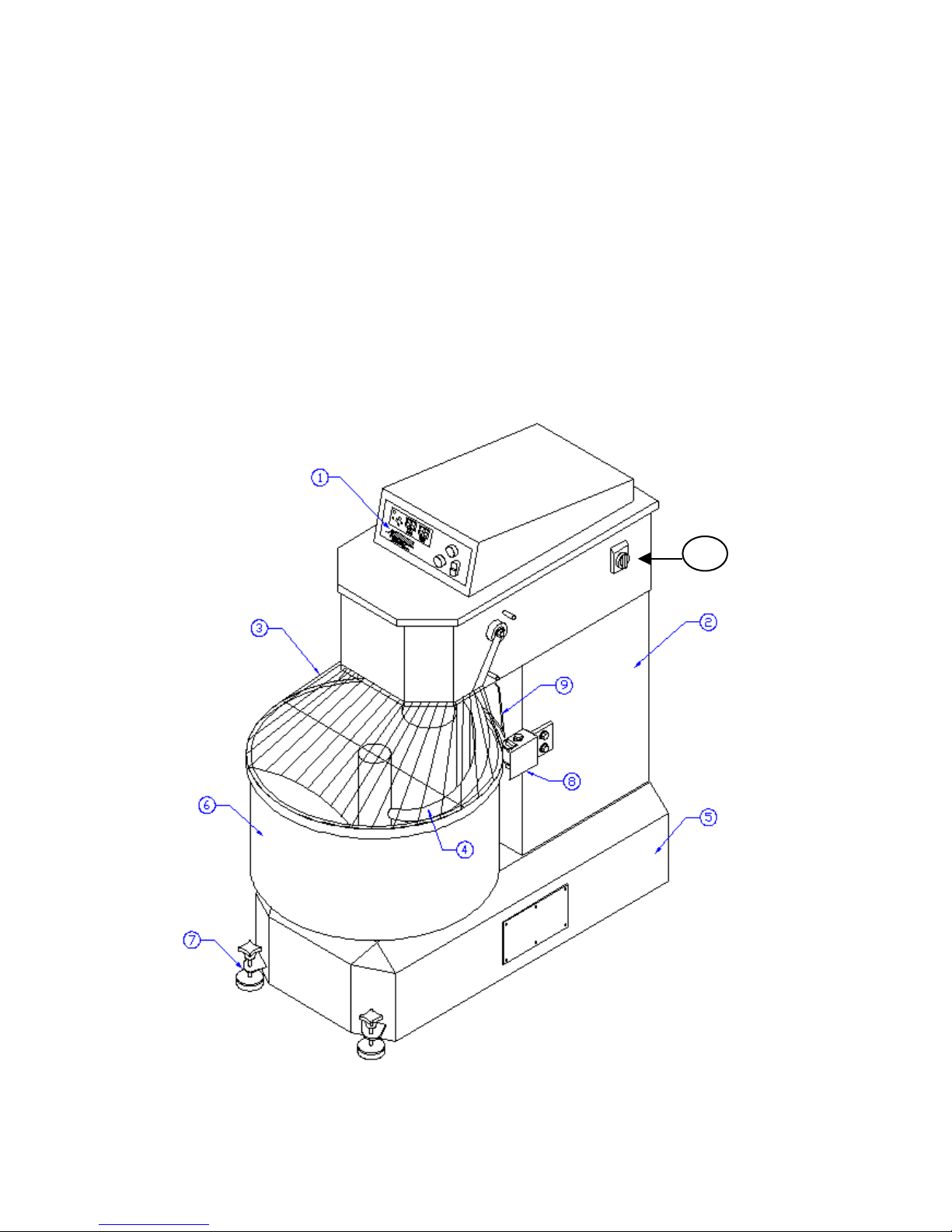
Figure # 3
1. Control panel
2. Machine structure
3. Security bars
4. Spiral
5. Bottom body
6. Stainless steel bowl
7. Machine floor fixer
8. Roller
9. Side board
10. Main switch
10
AEF-A.DOC 02/2003
5
Page 7
3.6 – SECURITY SYSTEM
The potentially most dangerous area on these machines is the one that surrounds the moving
spiral.
So, there is a safety guard that obstructs the entry in this area. This safety guard is designed
in a way to allow the user to watch the dough.
If you lift the safety guard, the machine will activate the micro switch and stop immediately.
To restart it, close the safety guard and press the green button “start”.
It is forbidden to remove, modify or damage the machine’s security bars.
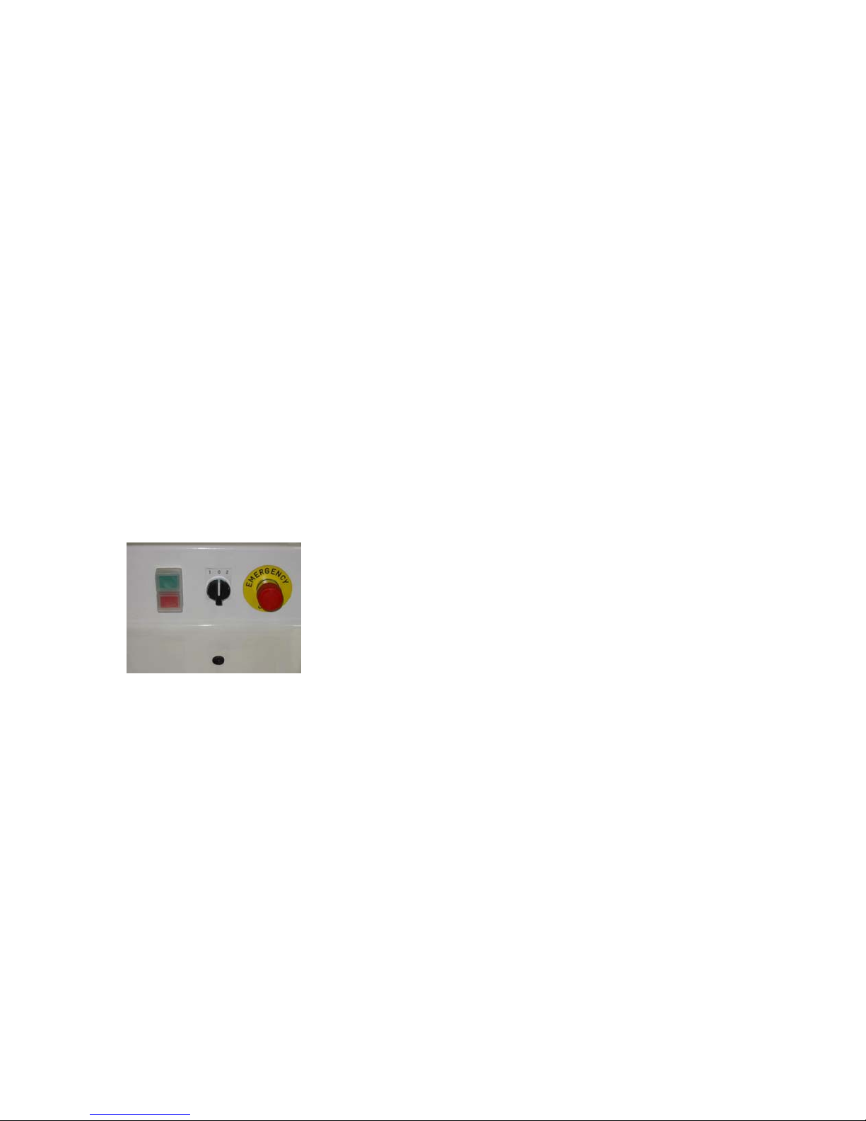
3.7 – CONTROL PANEL
AEF 015 fig.2
Start button (GREEN): If you push it, the machine will start.
Stop button (RED): If you push it, the machine will stop.
Selector switch: For 1st and 2
nd
speed.
Emergency stop button: If you push it, the machine will stop immediately.
Fig. 2
3.8 – EMERGENCY STOP
The machine has a mechanism that allows the user to stop it when necessary, blocking the
electric power. To re-establish the normal work of the machine, after having pressed this
button, the user must turn it as shown by the arrows.
AEF-A.DOC 02/2003
6
Page 8
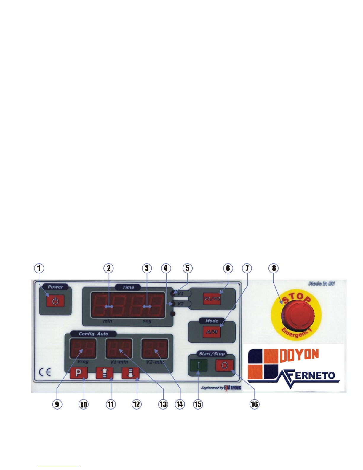
AEF 035/050/080/100/120 Fig.4
Figure # 4
1. Switch on and off button
2. Display to visualise the working minutes
3. Display to visualise the working seconds
4. Light of 2nd speed
5. Light of 1st speed
6. Speed selector button V1/V2
7. AUT/MANUAL mode selector button
8. Emergency stop
9. Display to visualise the programs
10. Programming button
11. Up button
12. Down button
13. Display to visualise the time of 1st speed
14. Display to visualise the time of 2nd speed
15. Start
16. Stop
• The machine also has a general switch (yellow and red). Position 0 (switch off), the
machine has no electric power.
Position I (switch on), the machine has electric power and the panel lights (point 6, fig.4),
and also will emit a sound signal.
AEF-A.DOC 02/2003
7
Page 9

Figure #5
1. Micro switch
2. Control panel
3. Electric motor.
4. Electric motor
5. Security bars
6. Current transformer
7. Switch
8. Contactor
9. Electric plug
10. Electric cable / cord
11. Main switch
AEF-A.DOC 02/2003
8
Page 10

CHAPTER 4
DOYON SPIRAL MIXER AEF 015
4.1 – ELECTRIC INFORMATION
• NEMA configuration L15-20P.
• Electrical supply installation must be in accordance with the electrical rating on the
nameplate.
• The plug should be near the machine and easily accessible.
4.2 – FIRST START
1. Turn the selector switch into position I (fig 2).
2. Close the safety bars (point 3, fig.3).
3. Verify if the red emergency STOP is not pressed (fig.2). If it is, you must turn the button
as shown by the arrows.
4. Press the green button and verify if the bowl and spiral rotation is the same as indicated
by the arrow. If not, stop immediately the machine, unplug it, open the electric plug and
reverse one phase for another.
5. When the machine starts working, verify if the protection bars work correctly. If not, stop
it, unplug it and contact a technician.
6. When the machine is new, you should, before starting production, try it with some
dough. This will remove the lubricator’s residuum, that may remain in the bowl and on
tools.
AEF-A.DOC 02/2003
9
Page 11

4.3- WORK START
• Turn the selector switch (1-0-2) to the desired speed, 1st or 2nd speed (fig. 2).
• Close the safety bars (point 3, fig.3). If you lift up the bars, the machine will stop
immediately.
• Press the start button to start the working cycle and a light will lighten up (fig.2).
• At the end of the working cycle, stop the machine by pressing the red Stop button and the
light on the (start/stop) switch will shut off.
• You may stop the machine at any time, by pressing the red emergency button.
4.4 – HOW TO STOP THE SPIRAL MIXER
There are four different ways to switch off the spiral mixer:
• Lift the safety bars;
• Push the red stop button;
• Push the red emergency stop switch;
• Turn the main switch into position 0.
AEF-A.DOC 02/2003
10
Page 12

DOYON SPIRAL MIXER AEF 035/050/080/100/120
4.1 – GENERAL CHARACTERISTICS
Electric commands come with two modes: manual and automatic mode
When in stand by, the displays shows four bars:
• 50 Different Programs capacity
• In each program you may adjust the time of work for the 1st and 2nd speed
•
Initial program is P1
MODEL
number
NEMA
Plug configuration
AEF015 L15-20P
AEF035 L15-20P
AEF050 15-30P
AEF080 15-50P
AEF100 15-50P
AEF120 15-50P
4.2 – ELECTRIC INFORMATION
• Electrical supply installation must be in accordance with the electrical rating on the
nameplate.
• The plug must be as near as possible of the machine and easily accessible.
4.3 – START
1. Turn the general switch into position I, and verify if the Emergency Stop is unlocked and
the points 2 and 3 will display (4bars _ _ _ _).
2. If the red emergency STOP button is pressed, you must turn the button as shown by the
arrows.
3. Close the safety bars (point 3, fig.3).
4. Press “POWER” (point 1, fig.4), the time display (point 2 and 3, fig.4) will display
“0.00”.
5. The machine always starts in manual mode.
6. Press the green button I (point 15, fig.4).
7. Verify if the bowl and spiral rotations are the same as indicated by the arrow on the
spiral. If not, stop immediately the machine, unplug it, open the electric plug and reverse
one phase for another.
8. When the machine starts working, verify if the protection bars work correctly, when you
lift it, the machine must stop. If not, contact a technician.
AEF-A.DOC 02/2003
11
Page 13

9. After that, push the Start button “I” (point 15, fig.4), the machine will restart. Then press
the red button “0” (point 16, fig 4) to stop the machine. If it doesn’t stop, push the
emergency stop, unplug it and call a technician.
When the machine is new, you should, before starting production, try it with some dough.
That will remove the lubricator’s residuum that may remain in the bowl and on the tools.
4.4 – MANUAL OPERATION
• Turn the main switch into position I (point 11, fig. 5) and verify if the Emergency Stop is
unlocked and the points 2 and 3 will display (4bars _ _ _ _).
• Close the safety bars (point 3, fig.3). If you lift up the bars, the machine will stop
immediately.
• Press “POWER”[ ] (point 1, fig.4), the time display (point 2 and 3, fig.4) will
display “0.00”.
• The machine starts in manual mode, to change it into automatic mode you just have to
press button (point7, fig.4) [ ], this button permits you to choose the mode.
• Use button (point 6, fig.4) [ ] to change speed.
• To start and stop the mixer, use buttons (point 15, fig.4) [ ] and (point 16, fig.4)
[ ].
•
The display (point 2 and 3, fig.4) shows the elapsed time in each speed.
• When working in 1st speed, you can change to 2nd speed at any time, pressing button
(point 6, fig.4). However, it is not possible to change from 2nd to 1st speed during the
work.
• At the end of the working cycle, stop the machine by pressing the red stop button (point
16, fig.4) [ ].
AEF-A.DOC 02/2003
12
Page 14

• At any time, it is possible to stop the machine by using the emergency stop (point 8, fig
4).
• The maximum working time of each speed is 60 minutes, and then the machine will stop
automatically.
4.5 – AUTOMATIC OPERATION
• Turn the general switch into position I, and verify if Emergency Stop is unlocked and
then press the power button (point 1, fig.4), the display (point 2 and 3, fig.4) will light
up.
• Close the safety bars (point 3, fig.3). If you lift up the bars, the machine will stop
immediately.
• The machine starts in manual mode, to change it into automatic mode you just have to
press button (point 7, fig.4) [ ] to choose the mode.
• When the automatic mode is selected, the displays 9,13 and 14 light and stay in Program
1.
• To select the program number, use the buttons 11[ ] and 12 [ ].
• The button 15 [ ], starts and restarts the selected program, the button 16 [ ]
stops the program and the working process.
AEF-A.DOC 02/2003
13
Page 15

• The display (point 2 and 3, fig.4) shows the elapsed time of the active speed. Display
(point 4 and 5, fig.4) shows the active speed.
• It is possible to adjust the programmed time by using the buttons 11[ ] and 12
[ ]. This change will not be programmed.
4.5.1 –WORKING CYCLE
• To start the working cycle, you must select the desired program, and then press the
button [ ] (point 15, fig. 4).
• The machine starts and lights at 1st speed. In the principal display (point 2 and 3, fig.4),
you will visualise the elapsed time and in displays (point 13 and 14, fig.4), the
programmed time.
• When the working time is the same as the programmed time, the machine will change
speed automatically. The 2nd speed lights the display (point 4, fig.4) and in display (point
2 and 3, fig.4), you will visualise the elapsed time of the programmed time (point 13 and
14, fig.4).
• When the working time is the same as the programmed time, the machine will stop
automatically. That is the end of the working cycle.
• At the end of the working cycle, press the red Stop button (point 16, fig.4) and the
display (point 2 and 3, fig4) comes to zero, so you can resume the work or start a new
cycle.
• You may stop the machine at any time, by pressing the stop button [ ](point 16,
fig.4), and resume the work by pressing the start button (point 15, fig.4) [ ]. The
working cycle will start from the stop point.
AEF-A.DOC 02/2003
14
Page 16

4.5.2 – CHANGING PROGRAMMED TIME DURING WORKING CYCLE.
• At any time during the working cycle, you can change the programmed time, by using
the buttons 11[
] or 12[ ]. This change only works for this period, that
means that at the end of the cycle, the program will return to the original values.
4.5.3 – STOP
• At any time, during the working cycle, you can stop the sequence, by pressing the stop
button 16 [
]. If you press the button 15[ ], the machine will resume the
work, but if you press continuously the stop button 16 [ ], you’ll get out of the
program.
• When the working cycle is completed the stop button 16 will light. Then, if you press it,
the cycle will end and the equipment is ready to start a new working cycle.
4.5.4 – SECURITY BARS
• If you lift up the safety bars during the working process, the machine will stop, and give
a sonorous signal.
• To restart the process, close the security bars and press again the start button 15
[ ].
4.6 – PROGRAMMING THE WORKING TIME
!
You can program 50 different programs, with time V1 and V2.
!
To program you must:
• Put the machine in automatic mode by pressing button 7 [ ].
• With buttons 11 [ ] and 12 [ ], select the program.
• For example, program 2.
AEF-A.DOC 02/2003
15
Page 17

• Edit the program by pressing the button 10 [ ] until it beeps.
• Use buttons 11 [ ] and 12 [ ] to select the time for first speed.
• Press button 10 [ ] to change from 1st to 2nd speed, and buttons 11
[ ] and 12 [ ] to select the time for 2nd speed.
• To finish, press button 10 [ ].
• The program is now memorised.
• Note : When entering the data in the selected program, you will have
approximately 10 seconds between each step to enter the desired settings. The
data will not be saved if you exceed 10 seconds between two settings and the
program will return to its original values.
4.7 – HOW TO STOP THE SPIRAL MIXER
There are four different ways to switch off the spiral mixer:
• Lift the safety bars;
• Push the red stop button [ ];
• Push the red emergency stop switch;
• When it is in automatic mode and the programmed cycle is expired, the machine will
stop automatically.
AEF-A.DOC 02/2003
16
Page 18

CHAPTER 5
MAINTENANCE AND CLEANING
Attention: Before doing maintenance and cleaning, switch off the machine with the main
switch and unplug it, some operations might be dangerous.
If you need to remove some protections, do not start working without them.
5.1. - WHEN THE MACHINE IS NEW
1. When the machine is new, you should, before starting production, try it with some
dough. This way, it will remove some lubricator’s residuum, resultant of the
manufacture.
2. After the 1st working month, you have to check the belts tension:
a) The transmission’s belts of the spiral may be examined by opening the cover of the
machine.
b) The transmission’s belts of the bowl may be examined by removing the access panel
on the bottom side of the machine.
c) To verify if the belt needs to be stretched, press the finger in the middle of the belt,
and if the looseness is superior to ½ in.(1 cm), there is a need to stretch it.
3. The electric equipment can be checked by lifting the cover of the machine and opening
the electric board.
4.
The motor can be checked by removing the access panel in the back of the machine.
5.2. - EVERY DAY
5.2.1. - MACHINE’S CLEANING
The machine must be cleaned every day, especially in the areas that have contact with the
dough (bowl, spiral, side board).
To clean the machine do not use knives, sandpaper, metallic objects, hard brushes or any tool
that may damage its surface. You may use plastic tools or soft sponges.
Do not use: toxic products, solvents, abrading agents or any products that may damage the
surfaces or the dough’s composition.
AEF-A.DOC 02/2003
17
Page 19

5.3 – EVERY 6 MONTHS
5.3.1 – CONTROL OF BELT’S STRETCHING
It is necessary to control the belts’ stretching every 6 months in all transmissions. If the belts
are too loose, the machine will lose power.
a) The transmission’s belts of the spiral can be examined by opening the cover of the
machine.
b) The transmission’s belts of the bowl can be examined by removing the access panel
on the bottom side of the machine.
c) To verify if the belt needs to be stretched, press a finger in the middle of the belt, and
if the looseness is superior to ½" (1 cm), there is a need to stretch it.
d) To stretch it, it is necessary to call an authorised technician.
AEF-A.DOC 02/2003
18
Page 20

CHAPTER 6
SAFETY INSTRUCTIONS
6.1 – SAFETY INSTRUCTIONS
• The machine must be used only for the functions that it has been conceived for. Doyon
Equipment will not be responsible for the damages caused by an improper, bad or
irrational use of the machine.
• Before cleaning or doing maintenance, turn the main switch off and unplug it.
• Do not remove security parts of the machine.
• If the machine has inactive security units, do not turn it on.
• The work of the machine may be stopped by using the red stop switch.
• If you detect any damages or bad functions of the machine, turn it off immediately and
call for an authorised technician, otherwise it may cause irreversible damages in the
machine.
• The electric connection must follow the procedures presented in the installation chapter.
6.2 – HAZARDS
1. SPIRAL
The spiral (point 4, fig.3) in movement is the most dangerous part of the machine.
The safety guard does not allow the access to this area (point 3, fig.3). You must not remove
it, damage it or modify it.
2. TRANSMISSIONS
Danger, the transmission must be protected with fixed protections. In order to have access to
them, you must respect the instructions of the manual.
AEF-A.DOC 02/2003
19
Page 21

3. ELECTRIC HAZARDS
The electric installation follows the Canadian, American and European security rules.
Nevertheless, respect the basic security rules in a way to avoid the risk of fire, electric
shocks, personal and material damages.
Only qualified people may access the parts that have electric current, which are obliged to:
1. Stop the machine
2. Turn off the main switch
3. Unplug the machine
4. Do the necessary operations
5. Plug the machine again
4. HYGIENIC HAZARDS
All the materials that are in contact with the dough, must be non toxic and inoffensive.
AEF-A.DOC 02/2003
20
Page 22

AEF-A.DOC 02/2003
21
Page 23

AEF-A.DOC 02/2003
22
Page 24

LIMITED WARRANTY
(Continental United States Of America And Canada Only)
Doyon Equipment Inc. guarantees to the original purchaser only that its product are free of
defects in material and workmanship, under normal use.
This warranty does not cover any light bulbs, thermostat calibration or defects due to or
resulting from handling, abuse, misuse, nor shall it extend to any unit from which the serial
number has been removed or altered, or modifications made by unauthorized service personnel
or damage by flood, fire or other acts of God. Nor will this warranty apply as regards to the
immersion element damaged by hard water.
The extent of the manufacturer’s obligation under this warranty shall be limited to the
replacement or repair of defective parts within the warranty period. The decision of the
acceptance of the warranty will be made by Doyon Equipment service department, which
decision will be final.
The purchaser is responsible for having the equipment properly installed, operated under normal
conditions with proper supervision and to perform periodic preventive maintenance.
If any parts are proven defective during the period of one year from date of purchase, Doyon
Equipment Inc. hereby guarantees to replace, without charge, F.O.B. Linière, Quebec, Canada,
such part or parts.
Doyon Equipment Inc. will pay the reasonable labor charges in connection with the replacement
parts occurring within one year from purchase date. Travel over 50 miles, holiday or overtime
charges are not covered. After one year from purchase date, all labor and transportation charges
in connection with replacement parts will be the purchaser’s responsibility.
Doyon Equipment Inc. does hereby exclude and shall not be liable to purchaser for any
consequential or incidental damages including, but not limited to, damages to property,
damages for loss of use, loss of time, loss of profits or income, resulting from any breach or
warranty.
In no case, shall this warranty apply outside Canada and continental United States unless the
purchaser has a written agreement from Doyon Equipment Inc.
 Loading...