

Page 1
ÉQUIPEMENT DOYON INC.
1255, rue Principale
Linière, Qc, Canada G0M 1J0
Tel.: 1 (418) 685-3431
Canada: 1 (800) 463-1636
US: 1 (800) 463-4273
FAX: 1 (418) 685-3948
Internet: http://www.doyon.qc.ca
e-mail: doyon@doyon.qc.ca
AEF 015, 025, 035, 050, 080, 100, 150
Product / Produit:
Serial number / Numéro de série:
Page 2

DOYON SPIRAL MIXER AEF 015/025/035/050/080/100/150
IMPORTANT SAFETY INSTRUCTIONS
READ AND SAVE THESE INSTRUCTIONS
DANGER
TO REDUCE THE RISK OF FIRE OR ELECTRIC SHOCK,
CAREFULLY FOLLOW THESE INSTRUCTIONS.
TABLE OF CONTENTS
TO GET THE BEST PERFORMANCE OF YOUR MACHINE, READ
CAREFULLY THIS MANUAL.
OPERATOR SECTION
CHAPTER 1 – RECEPTION OF THE MERCHANDISE. . . . . . . . . . . . . . . . . . . . . 2
WARNING SAFGUARDS. . . . . . . . . . . . . . . . . . . . . . . . . . . . . . . . . . . 3
SAFETY INSTRUCTIONS. . . . . . . . . . . . . . . . . . . . . . . . . . . . . . . . . . . 4
CHAPTER 2 – GENERAL DIMENSIONS. . . . . . . . . . . . . . . . . . . . . . . . . . . . . . . 5
CHAPTER 3 - TECHNICAL DATA
3.1. – General description . . . . . . . . . . . . . . . . . . . . . . . . . . . . . . . 6
3.2. – Technical characteristics . . . . . . . . . . . . . . . . . . . . . . . . . . . . 7
3.3. – Electrical characteristics. . . . . . . . . . . . . . . . . . . . . . . . . . . . . 7
3.4. – Damage situations . . . . . . . . . . . . . . . . . . . . . . . . . . . . . . . . . 7
3.5. – Electric installation . . . . . . . . . . . . . . . . . . . . . . . . . . . . . . . . 7
3.6. – Security system . . . . . . . . . . . . . . . . . . . . . . . . . . . . . . . . . . . 9
3.7. – Emergency stop. . . . . . . . . . . . . . . . . . . . . . . . . . . . . . . . . . . . . 9
3.8. – Parts description. . . . . . . . . . . . . . . . . . . . . . . . . . . . . . . . . . . . . 10
CHAPTER 4 – SPIRAL MIXER OPERATION
AEF 015/025/035/050/080/100/150
4.1. – General characteristics . . . . . . . . . . . . . . . . . . . . . . . . . . . . . . 11
4.2. – Electric information . . . . . . . . . . . . . . . . . . . . . . . . . . . . . . . . 11
4.3. – Start . . . . . . . . . . . . . . . . . . . . . . . . . . . . . . . . . . . . . . . . . . . . . 11
4.4. – Manual working process . . . . . . . . . . . . . . . . . . . . . . . . . . . . . 12
4.5. – Automatic working process . . . . . . . . . . . . . . . . . . . . . . . . . . 13
4.6. – Programming the automatic working time . . . . . . . . . . . . . . . 14
4.7. – How to stop the spiral mixer . . . . . . . . . . . . . . . . . . . . . . . . . 15
4.8. – Alarm messages . . . . . . . . . . . . . . . . . . . . . . . . . 16
Page 3

CHAPTER 5 – CLEANING
5.1. – Every day . . . . . . . . . . . . . . . . . . . . . . . . . . . . . . . . . . . . . . . . 18
QUALIFIED TECHNICIANS MAINTENANCE SECTION
CHAPTER 6 – MAINTENANCE SECTION FOR QUALIFIED TECHNICIANS
6.1. – Every 6 months . . . . . . . . . . . . . . . . . . . . . . . . . . . . . . . . . . . . 19
6.1.1 – Belting system adjustments . . . . . . . . . . . . . . . . . . . . . . . . . . . 19
ELECTRIC SCHEMATICS
AEF 015/025 1 Phase. . . . . . . . . . . . .. . . . . . . . . . . . . . . . . . . . . . . . . . .20
AEF 025 3 phases. . . . . . . . . . . . . . . . . . . . . . . . . . . . . . . . . . . . . . . . . 21
AEF035/050/080/100/150 3 phases . . . . . . . . . . . . . . . . . . . . . . . . . . . .22
LIMITED WARRANTY
Warranty . . . . . . . . . . . . . . . . . . . . . . . . . . . . . . . . . . . . . . . . . . . . . . . 23
AEF-A.DOC 04/2007
1
Page 4

CHAPTER 1
CAUTION
READ ALL INSTRUCTIONS
The spiral mixers are manufactured with first quality material by experienced technicians. Proper
installation and maintenance will guarantee a reliable service for years to come.
A nameplate specifies the model number, serial number, voltage, amperage, frequency and
manufacturing date.
Drawings, electrical diagram and replacement parts numbers are included in this manual.
ATTENTION
DOYON is not responsible for damages to the property or the equipment
caused by personnel who is not certified by known organisations.
SHIPPING
For your safety, this equipment has been verified by qualified technicians and carefully crated
before shipment. The freight company assumes full responsibility concerning the delivery in good
condition of the equipment in accepting to transport it.
IMPORTANT
RECEPTION OF THE MERCHANDISE
Take care to verify that the received equipment is not damaged before signing the delivery receipt.
If a damage or a lost part is noticed, write it clearly on the receipt. If it is noticed after the carrier
has left, contact immediately the freight company in order that they do their inspection.
We do not assume the responsibility for damages or losses that may occur during transportation.
INSTALLATION WARNINGS
CAUTION
To ensure continued protection against risk or electric shock,
connect to properly earthed outlets only.
INSTALLATION AND SERVICE
The spiral mixer must be connected to the utility and electrically grounded in conformity to the
effective local regulations. If these are not established, the machine must be connected according
to the National Electrical Code (NFPA 70-XX). This equipment has a male plug that meets
those requirements.
AEF-A.DOC 04/2007
2
Page 5

IMPORTANT SAFEGUARDS
Read all instructions.
Remove plug from the outlet when the appliance is not in use, before putting
on or taking off parts, and before cleaning.
Do not use outdoors.
Do not let cord hang over edge of table or counter or touch hot surfaces.
Do not operate any appliance with a damaged cord or plug or after the
appliance malfunctions or is dropped or damaged in any manner. Return
appliance to the nearest authorized service facility for examination, repair
or electrical or mechanical adjustment.
The use of accessory attachments not recommended by the appliance
manufacturer may cause injuries.
Do not place on or near a hot gas or electric burner or in a heated oven.
Always check if the control switch is OFF before plugging cord into wall
outlet. To disconnect, turn the control switch to OFF, then remove plug from
wall outlet.
Do not use appliance for other than intended use.
AEF-A.DOC 04/2007
3
Page 6

SAFETY INSTRUCTIONS
– SAFETY INSTRUCTIONS
• The machine must be used only for the functions that it has been conceived for. Doyon
Equipment will not be responsible for the damages caused by an improper, bad or irrational
use of the machine.
• Before cleaning or doing maintenance, turn the main switch off and unplug it.
• Do not remove security parts of the machine.
• If the machine has inactive security units, do not turn it on.
• The work of the machine may be stopped by using the red stop switch.
• If you detect any damages or bad functions of the machine, turn it off immediately and call
for an authorised technician, otherwise it may cause irreversible damages in the machine.
• The electric connection must follow the procedures presented in the installation chapter.
– CAUTION
1. SPIRAL
The spiral (point 4, fig.2) in movement is the most dangerous part of the machine.
The safety guard does not allow the access to this area (point 3, fig.2). You must not remove it,
damage it or modify it.
2. TRANSMISSIONS
Danger, the transmission must be protected with fixed protections. In order to have access to
them, you must respect the instructions of the manual.
ELECTRIC CAUTION
The electric installation follows the Canadian, American and European security rules.
Nevertheless, respect the basic security rules in a way to avoid the risk of fire, electric shocks,
personal and material damages.
Only qualified people may access the parts that have electric current, which are obliged to:
1. Stop the machine
2. Turn off the main switch
3. Unplug the machine
4. Do the necessary operations
5. Plug the machine again
Save these instructions.
AEF-A.DOC 04/2007
4
Page 7

CHAPTER 2
GENERAL DESCRIPTION
Doyon Spiral Mixers are designed to be used by qualified people in the Bakery production.
The particular shapes and speeds of the spirals and bowls allow you to have in a short period of
time, very smooth dough, even when small quantities of water are used. Our spiral mixers are
able to work with small quantities of flour (for instance, the mixer of 220 Lbs. of flour may
work with 11 Lbs. of flour).
It also has a very simple control panel, easy to work with. You may choose between the
automatic or manual mode, each mode come with two speeds.
AEF-A.DOC 04/2007
5
Page 8
CHAPTER 3
TECHNICAL DATA
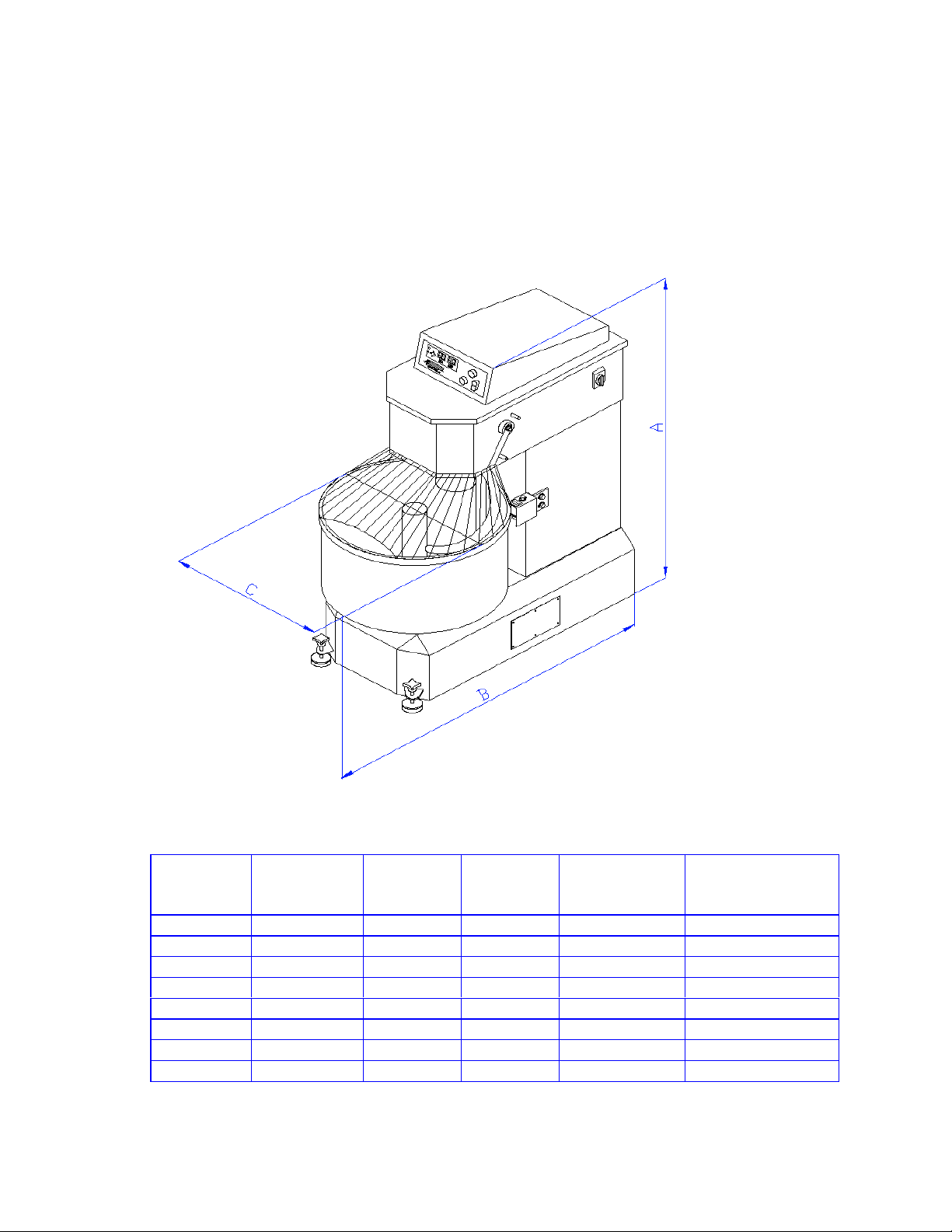
3.1 – GENERAL DIMENSIONS AND SPECIFICATIONS
Fig.1
Dimensions and specifications of spiral mixers:
A
Model
AEF 015SP 41"(104) 29"(73.5) 16"(40.5) 2.2-33 (1-15) 3.5-50 (1.5-25)
AEF 025SP 41.5"(105.4) 32. ¼(82) 19"(48.25) 4.5-55 (2-25) 3.5-80 (3.5-40)
AEF 025 41.5"(105.4) 32. ¼(82) 19"(48.25) 4.5-55 (2-25) 3.5-80 (3.5-40)
AEF 035 46 ¼ "(118.5) 41"(104) 21 ½"(54.5) 4.5-75 (2-35) 8-130 (3.5-55)
AEF 050 51"(129.5) 46"(117) 27"(68.5) 7-110 (3-50) 12-175 (5.5-80)
AEF 080 54"(142) 60"(152.4) 31"(75.5) 11-175 (5-80) 18-280 (8-125)
AEF 100 54"(142) 64"(162) 34"(86.5) 22-240 (10-110) 35-380 (16-175)
AEF 150 54"(142) 64"(162) 39"(99) 22-330 (10-150) 35-520 (16-235)
AEF-A.DOC 04/2007
Inch (cm)
B
Inch (cm)CInch (cm)
Flour Capacity
Lbs (kg)
Dough
Capacity
Lbs. (kg)
6
Page 9

3.2. – TECHNICAL CHARACTERISTICS
• Steel body.
• Independent electric motors for stainless steel hook and bowl (except AEF015 & AEF025).
• Belt driven transmission.
• Two speeds on stainless steel hook.
• Two speeds on stainless steel bowl.
• Safety guard with micro switch.
• Manual and automatic digital control with 9 memories of desired working time.
• Heavy-duty painting.
3.3 – ELECTRICAL CHARACTERISTICS
• The spiral mixers AEF015 are available 208-240 volts. 1 Phase only.
• The spiral mixers AEF025 are available 208-240 volts. 1 and 3 Phases.
• The spiral mixers AEF035 to AEF150 are available 208-240 volts. 3 Phases only.
• Speed – 900 R.P.M. for 1st speed and 1800 R.P.M. for 2nd speed.
• Frequency – 60 Hz
• 208-240 volts
• 1 or 3 phases
• 3 or 4 wires (2 or 3 lines + Gnd)
3.4 – THE MANUFACTURER IS NOT RESPONSIBLE FOR THE MACHINE’S
DAMAGES IN THE FOLLOWING SITUATIONS:
• Bad use of the machines.
• Using them out of the national laws.
• Problems with electric power.
• Non-authorised changes.
• Deficient upkeep.
• Use of unoriginal parts and products of the machines.
• Not following this manual.
• Repairs made by unauthorised technicians.
3.5 – ELECTRIC INSTALLATION
Doyon’s machines have an electric installation in compliance with the American (ANSI/UL
std. 763), Canadian (CSA std. C22.2 no. 1335.2.14) and European rules.
AEF-A.DOC 04/2007
7
Page 10
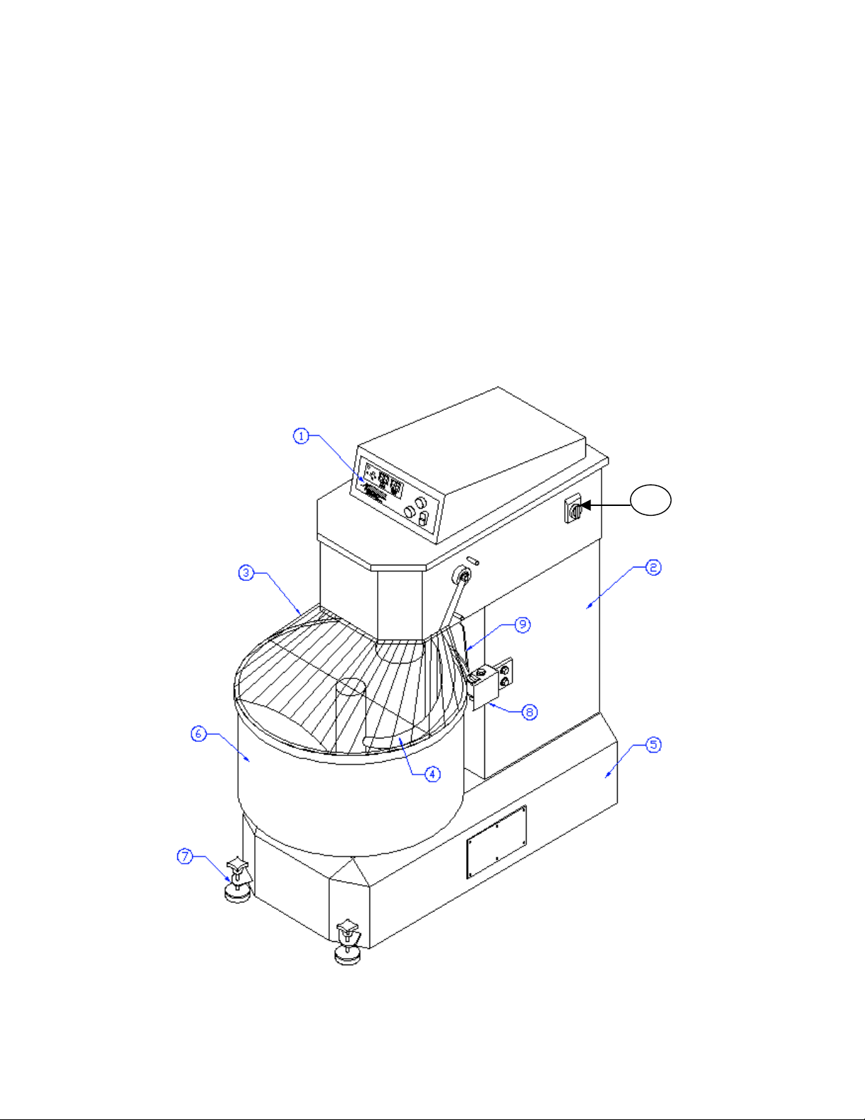
Figure # 2
1. Control panel
2. Machine structure
3. Security bars
4. Spiral
5. Bottom body
6. Stainless steel bowl
7. Machine floor fixer
8. Roller
9. Side board
10. Main switch
10
AEF-A.DOC 04/2007
8
Page 11

3.6 – SECURITY SYSTEM
The potentially most dangerous area on these machines is the one that surrounds the moving
spiral.
So, there is a safety guard that obstructs the entry in this area. This safety guard is designed in a
way to allow the user to watch the dough.
If you lift the safety guard, the machine will activate the micro switch and stop immediately.
To restart it, close the safety guard and press the green button “start”.
It is forbidden to remove, modify or damage the machine’s security bars.
3.7 – EMERGENCY STOP
The machine has a mechanism that allows the user to stop it when necessary, blocking the
electric power. To re-establish the normal work of the machine, after having pressed this
button, the user must turn it as shown by the arrows.
AEF-A.DOC 04/2007
9
Page 12
3.8 – PARTS DESCRIPTION
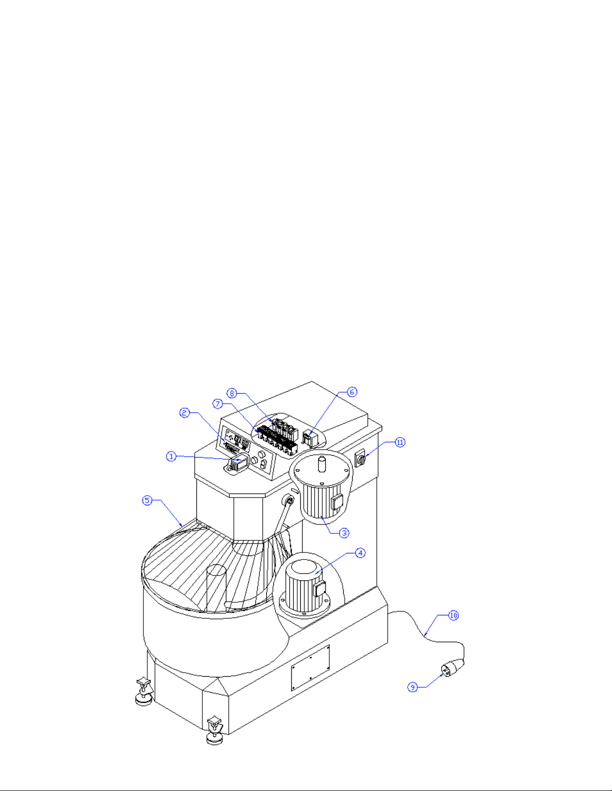
AEF 015/025/035/050/080/100/150 Fig.3
Figure # 3
1. Micro switch
2. Control panel
3. Electric hook motor. (Drive Hook and bowl for AEF015 & AEF025)
4. Electric bowl motor. (except for AEF015 & AEF025 the hook motor also drive the bowl)
5. Security bars
6. Current transformer
7. Switch
8. Contactor
9. Electric plug
10. Electric cable / cord
11. Main switch
Note: The AEF015 and AEF025 do not have part # 4, only the motor part # 3 to drive the hook
and the bowl
Note : on The AEF015SP and AEF025SP parts # 6, 7 and 8 are replace by a motor drive
inverter Fuji Frenic-mini FRN 1.5 C1S-7 for AEF015SP and Fuji Frenic-mini FRN 2.2 C1S-7
for AEF025SP
AEF-A.DOC 04/2007
10
Page 13
CHAPTER 4
DOYON SPIRAL MIXER AEF 015/025/035/050/080/100/150
OPERATION
4.1.- GENERAL CHARACTERISTICS
• Electric commands with two modes: manual or automatic mode.
• 9 different program capacities.
• In each program, you may adjust the time of work for the 1st and 2nd speed.
• Low tension.
• Initial program is 1.
• Protection fuse of 750mA.
4.2.- ELECTRICAL INFORMATION
• Electrical supply installation must be in accordance with the electrical rating on the
nameplate.
• The plug must be as near as possible of the machine and easily accessible.
MODEL
number
AEF015SP 6-20P
AEF025SP 6-20P
AEF025 L15-20P
AEF035 L15-20P
AEF050 15-30P
AEF080 15-50P
AEF100 15-50P
AEF150 15-50P
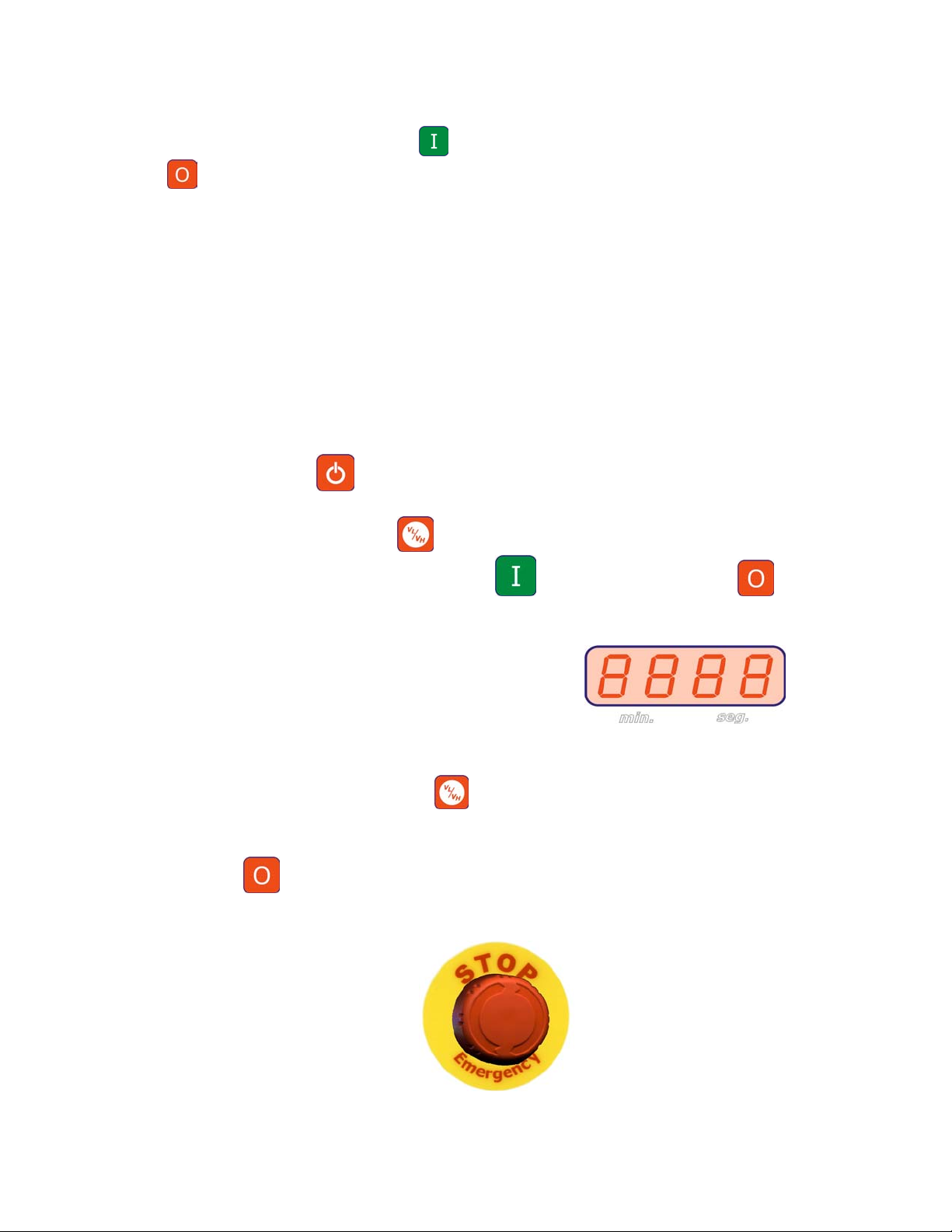
4.3.- START
• Turn the general switch into position I and verify if Emergency “Stop” is unlocked and if
the displays (point 3,5,12,13,14,15 e 16) are illuminated.
• When the general switch is on, it will show the serial number of the plate in the display,
point 3, figure 4.
• If the red Emergency “Stop” button is pressed (point 22, figure 4), you must turn the button
as shown by the arrows.
• Close the safety guards (point 3, figure 2).
• The machine always starts in manual mode.
NEMA
Plug configuration
• Press the button 1 [ ] and the displays 12,13,14,15 and 16 lights down.
• Press the green button (point 8, figure 4).
• Verify if the bowl and spiral rotations are the same as indicated by the arrow on the spiral.
If not, stop immediately the machine, unplug it, open the electric plug and reverse one
phase for another.
AEF-A.DOC 04/2007
11
Page 14
• When the machine starts working, verify if the safety guards work correctly, when you lift
it, the machine must stop. If not, contact a technician.
• After that, push the Start button , the machine will restart. Then, press the red button
(point 9, figure 4), to stop the machine. If it doesn’t stop, pull the emergency stop,
unplug it and call a technician.
When the machine is new, you should, before starting production, try it with some dough. That
will remove the lubricator’s residuum that may remain in the bowl and on the tools.
4.4.- MANUAL OPERATION
• Turn the main switch into position I, verify if the Emergency STOP button is unlocked and
verify if panel lights (point 3 and 5, figure 4) are up.
• Close the safety guards (point 3, figure 2). If you lift up the safety guards, the machine will
stop immediately and the word “OPEN” will appear in display 3.
• The machine always starts working in Manual Mode.
• Press the button 1 [ ] and the displays 12,13,14,15 and 16 lights down.
• Use button (point 4, figure 4) [ ] to change speed.
• To start and stop the mixer, use buttons [ ] (point 8, figure 4) and [ ] (point 9,
figure 4).
• The display 3 shows the elapsed time in each speed.
• The display 5 shows the speed that is working.
• When working in slow speed (VL), you can change to high speed (VH) at any time,
pressing button (point 4, figure 4) [
st
speed during the work.
1
]. However, it is not possible to change from 2nd to
• At the end of the working cycle, stop the machine by pressing the red stop button (point 9,
figure 4) [ ].
• At any time, it is possible to stop the machine by using the emergency stop (point 22, figure
4).
• The maximum working time of the each speed is 60 minutes, and then the machine will
stop automatically.
AEF-A.DOC 04/2007
12
Page 15
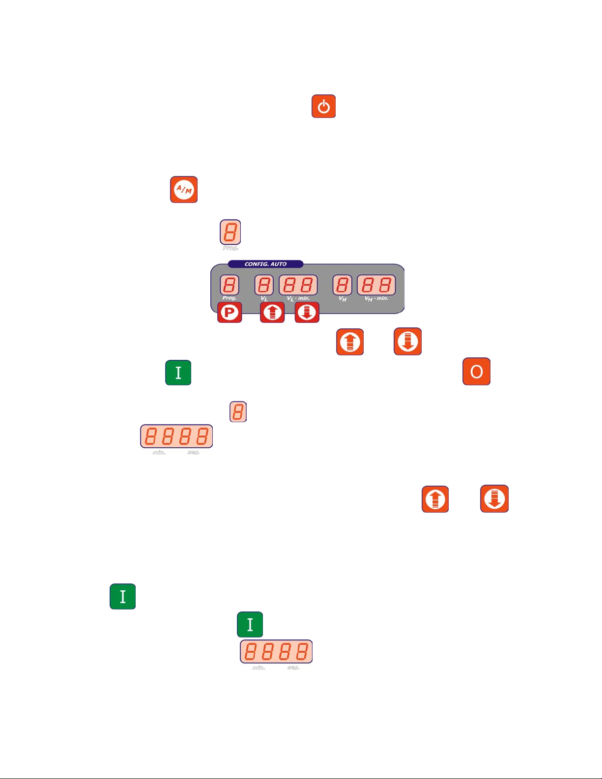
4.5.- AUTOMATIC OPERATION
• Turn the general switch into position I, and verify if Emergency Stop is unlocked and then
press the power button (point 1, figure 4) , the display (point 3 and 5, figure 4) will
light up.
• Close the safety guards (point 3, figure 2). If you lift up the safety guards, the machine will
stop immediately (in the display 3 it will show the word OPEN).
• The machine starts in manual mode, to change it into automatic mode, you just have to
press button [ ] (point 2, figure 4) to choose the mode.
• When the automatic mode is selected, the displays (point 12,13,14,15 and 16, figure 4)
light and the display 12
shows the number of the program.
• To select the program numbers, use the buttons [ ] and [ ] (point 11, figure 4) .
• The button [ ] starts and restarts the selected program and the button [ ] stops the
program and the working process.
The display “speed” (point 5, figure 4) shows the active speed and
display the elapsed time of the active speed.
• During the work of the program, the display of the time of the active speed is blinking.
• It is possible to adjust the programmed time by using the button [ ] and [ ]. This
change will not be programmed.
4.5.1. - Working cycle
• To start the working cycle, you must select the desired program, and then press the button
[ ] (point 8, figure 4).
• After pressing the button [ ] (point 8, figure 4), the machine starts. In the principal
display (point 3, figure 4) , you will visualise the elapsed time and in
displays (point 14 and 16, figure 4), the programmed time.
• When the machine is working in slow speed, the display of slow speed (point 13, figure 4)
and of the programmed time in VL-min will start blinking.
AEF-A.DOC 04/2007
13
Page 16

• When the working time is the same as the programmed time, the machine will change
automatically. The high speed, VH, lights (point 15, figure 4) and the display of the
programmed time in VH-min will be blinking (point 16, figure 4). In the display 3 you will
visualise the elapsed time and in the point 14 and 16, figure 4, the programmed time.
• When the working time is the same as the programmed time, the machine will stop
automatically. That is the end of the working cycle.
• At the end of the working cycle, press the red stop button (point 9, figure 4) [ ] and the
display (point 3, figure 4) comes to zero, so you can resume the work or start a new cycle.
• You may stop the machine at any time by pressing button stop [ ] and resume the
work by pressing button [ ]. The working cycle will start from the stop point.
4.5.2.- Changing the programmed time during the working cycle
• At any time during the working cycle, you can change the programmed time, by using the
button [ ] or [ ]. This change only works for this period and that means that at the
end of the cycle, the program will return to the original values.
4.5.3.- Stop the machine
• At any time during the working cycle, you can stop the sequence by pressing de button
[ ]. If you press again the button [ ], the machine will resume the work, but if you
press continuously the button [ ], you will get out of the program.
• When the working cycle is completed, the equipment is ready to start a new working cycle.
4.5.4. - Safety guards
• If you lift up the safety guards during the working process, the machine will stop and give a
sonorous signal.
• To restart the process, close the safety guards and press again the button [ ].
4.6. - PROGRAMMING THE WORKING TIME
• You can program 9 different programs, with time to VL and VH.
• To program you must :
o Put the machine in automatic mode by pressing button [ ].
AEF-A.DOC 04/2007
14
Page 17

o
With buttons [ ] and [ ], select the program.
o For example, program 1.
• Edit the program by pressing the button [ ] until it shows PROG in the display 3.
• Use the buttons [ ] and [ ] to select the number of the program that is to change
(display 12).
• Press the button [ ] to go to the speed VL.
• Press again the button [ ] and the display VL-min starts blinking.
• Use the buttons [ ] and [ ] to select the working time selected in low speed VL.
• After selecting the desired programming time to the slow speed, press the button [ ] to
change to high speed VH.
• Press again the button [ ] and the display VH-min starts blinking.
• Use the buttons [ ] and [ ] to select the working time selected in high speed VH.
• Press button the button [ ] until it shows in the display 3 the word “SAVE”.
• The program is now memorised.
4.7.- HOW TO STOP THE SPIRAL MIXER
There are four different ways to switch off the spiral mixer:
• Lift the safety guards.
• Push the red stop button [ ].
• Push the red emergency stop switch.
• When in automatic mode, if the programmed time expires, the machine will stop
automatically.
AEF-A.DOC 04/2007
15
Page 18

Figure #4
1. On and Off switch.
2. Automatic/ Manual mode selector switch.
3. Display to visualise the elapsed working time.
4. Speed selector button : V Low / V High.
5.Speed light..
8. Start.
9. Stop.
11. Programming button : Up velocity / Down Velocity.
12. Display to visualise the program number.
13. Display to visualise low velocity.
14. Display to visualise the time of low velocity.
15. Display to visualise high velocity.
16. Display to visualise the elapsed time of high velocity
22. Emergency Stop.
CONTROL MECHANISM
Figure 4 presents the control panel of the spiral mixer:
• Point 1: ON/OFF button.
• Point 2: Selector switch for the manual or automatic mode.
• Point 4: Selector switch for first and second speed.
• Point 8: Switch ON ; starts the motors.
• Point 9: Switch OFF ; stops the motors.
• Point 11: Programming button.
AEF-A.DOC 04/2007
16
Page 19

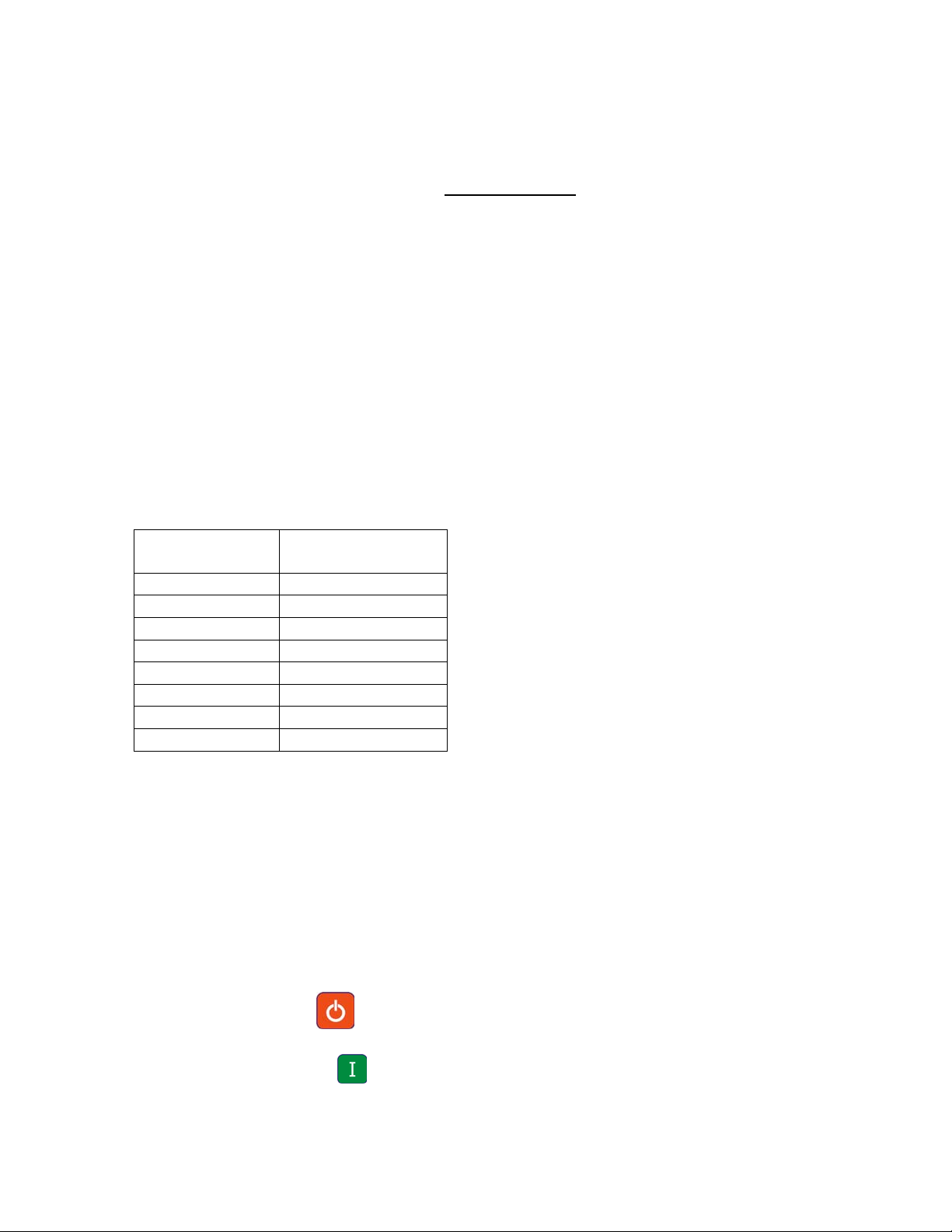
4.8. ALARM MESSAGES
There are 4 different types of Alarm:
Description of the Breakdown Possible Solution
Error 1 Error in the processor (memory).
It means that the micro controller
cannot read and/or write in the
memory where the programs are
stored.
Error 2 Error in the processor (memory).
Note: before the alarm 2
appears, the message “INSP” is
shown in displays 2 and 3. This
message is only to advise you
that alarm 2 will soon be
activated.
Error 3 Error in the processor. Contact Technical Support
Error 4 Too much effort on the machine.
The motor’s protection overload
relays were activated. This could
be caused by effort when
kneading too hard dough or by
other attrition.
In all circumstances, first turn off the machine by using the main switch [ ] during
approximately 10 minutes. The error may be eliminated if caused by a temporary reason.
Several alarms may appear at the same time, for instance 3 and 4.
Change the electronic board.
Contact Technical Support.
Unplug the machine. Diminish the
machine’s load. Communicate this
error to the Technical Support.
AEF-A.DOC 04/2007
17
Page 20

CHAPTER 5
OPERATOR MAINTENANCE AND CLEANING
Attention: Before doing maintenance and cleaning, switch off the machine with the main
switch and unplug it, some operations might be dangerous.
If you need to remove some protections, do not start working without them.
5.1. - EVERY DAY
5.1.1. - MACHINE’S CLEANING
The machine must be cleaned every day, especially in the areas that have contact with the
dough (bowl, spiral, side board).
To clean the machine do not use knives, sandpaper, metallic objects, hard brushes or any tool
that may damage its surface. You may use plastic tools or soft sponges.
Do not use: toxic products, solvents, abrading agents or any products that may damage the
surfaces or the dough’s composition.
AEF-A.DOC 04/2007
18
Page 21

THIS SECTION NEED TO DONE BY A QUALIFIED
TECHNICIAN.
6.1 – EVERY 6 MONTHS
6.1.2 – CONTROL OF BELT’S STRETCHING
It is necessary to control the belts’ stretching every 6 months in all transmissions. If the belts
are too loose, the machine will lose power.
a) The transmission’s belts of the spiral can be examined by opening the cover of the
machine.
b) The transmission’s belts of the bowl can be examined by removing the access panel on
the bottom side of the machine.
c) To verify if the belt needs to be stretched, press a finger in the middle of the belt, and if
the looseness is superior to ½" (1 cm), there is a need to stretch it.
d) To stretch it, it is necessary to call an authorised technician.
6.1.2 – SAFETY INSTRUCTIONS
• The machine must be used only for the functions that it has been conceived for. Doyon
Equipment will not be responsible for the damages caused by an improper, bad or irrational
use of the machine.
• Before cleaning or doing maintenance, turn the main switch off and unplug it.
• Do not remove security parts of the machine.
• If the machine has inactive security units, do not turn it on.
• The work of the machine may be stopped by using the red stop switch.
• If you detect any damages or bad functions of the machine, turn it off immediately and call
for an authorised technician, otherwise it may cause irreversible damages in the machine.
• The electric connection must follow the procedures presented in the installation chapter.
6.1.3 – CAUTION
CAUTION
The spiral (point 4, fig.2) in movement is the most dangerous part of the machine.
The safety guard does not allow the access to this area (point 3, fig.2). You must not remove it,
damage it or modify it.
CAUTION
Danger, the transmission must be protected with fixed protections. In order to have access to
them, you must respect the instructions of the manual.
AEF-A.DOC 04/2007
19
Page 22

AEF-A.DOC 04/2007
20
Page 23

AEF-A.DOC 04/2007
21
Page 24

AEF-A.DOC 04/2007
22
Page 25

LIMITED WARRANTY
(Continental United States Of America And Canada Only)
Doyon Equipment Inc. guarantees to the original purchaser only that its product are free of
defects in material and workmanship, under normal use.
This warranty does not cover any light bulbs, thermostat calibration or defects due to or
resulting from handling, abuse, misuse, nor shall it extend to any unit from which the serial
number has been removed or altered, or modifications made by unauthorized service personnel
or damage by flood, fire or other acts of God. Nor will this warranty apply as regards to the
immersion element damaged by hard water.
The extent of the manufacturer’s obligation under this warranty shall be limited to the
replacement or repair of defective parts within the warranty period. The decision of the
acceptance of the warranty will be made by Doyon Equipment service department, which
decision will be final.
The purchaser is responsible for having the equipment properly installed, operated under normal
conditions with proper supervision and to perform periodic preventive maintenance.
If any parts are proven defective during the period of one year from date of purchase, Doyon
Equipment Inc. hereby guarantees to replace, without charge, F.O.B. Linière, Quebec, Canada,
such part or parts.
Doyon Equipment Inc. will pay the reasonable labor charges in connection with the replacement
parts occurring within one year from purchase date. Travel over 50 miles, holiday or overtime
charges are not covered. After one year from purchase date, all labor and transportation charges
in connection with replacement parts will be the purchaser’s responsibility.
Doyon Equipment Inc. does hereby exclude and shall not be liable to purchaser for any
consequential or incidental damages including, but not limited to, damages to property,
damages for loss of use, loss of time, loss of profits or income, resulting from any breach or
warranty.
In no case, shall this warranty apply outside Canada and continental United States unless the
purchaser has a written agreement from Doyon Equipment Inc.
Page 26

MÉLANGEUR SPIRAL DOYON AEF 015/025/035/050/080/100/150
IMPORTANT INSTRUCTIONS DE SÉCURITÉ
LIRE ET GARDEZ CE MANUEL D’INSTRUCTIONS
DANGER
AFIN DE RÉDUIRE LES RISQUES D’INCENDIE OU D’ÉLECTROCUTION,
SUIVRE CES INSTRUCTIONS AVEC SOIN.
TABLE DES MATIÈRES
POUR OBTENIR DE MEILLEURS RÉSULTATS, VEUILLEZ LIRE
ATTENTIVEMENT CE MANUEL.
CHAPITRE 1 – RÉCEPTION DE LA MARCHANDISE . . . . . . . . . . . . . . . . . . . . . 2
IMPORTANTE MESURES DE SÉCURITÉ. . . . . . . . . . . . . . . . . . . . . 3
INSTRUCTIONS DE SÉCURITÉ. . . . . . . . . . . . . . . . . . . . . . . . . 4
CHAPITRE 2 – DESCRIPTION GÉNÉRALE . . . . . . . . . . . . . . . . . . . . . . . . . . . . . . 5
CHAPITRE 3 – INFORMATIONS TECHNIQUES
3.1. – Dimension générale . . . . . . . . . . . . . . . . . . . . . . . . . . . . . . . 6
3.2. – Caractéristiques techniques . . . . . . . . . . . . . . . . . . . . . . . . . . 7
3.3. – Caractéristiques électriques . . . . . . . . . . . . . . . . . . . . . . . . . . 7
3.4. – Dommages . . . . . . . . . . . . . . . . . . . . . . . . . . . . . . . . . . . . . . . 7
3.5. – Installation électrique . . . . . . . . . . . . . . . . . . . . . . . . . . . . . . . 7
3.6. – Système de sécurité. . . . . . . . . . . . . . . . . . . . . . . . . . . . . . . . . 9
3.7. – Arrêt d’urgence. . . . . . . . . . . . . . . . . . . . . . . . . . . . . . . . . . . . 9
3.8. – Description des pièces . . . . . . . . . . . . . . . . . . . . . . . . . . . . . . . . .10
CHAPITRE 4 – L’UTILISATION DU MÉLANGEUR SPIRAL
AEF 015/025/035/050/080/100/150
4.1. – Caractéristiques générales . . . . . . . . . . . . . . . . . . . . . . . . . . . 11
4.2. – Informations électriques . . . . . . . . . . . . . . . . . . . . . . . . . . . . 11
4.3. – Démarrage . . . . . . . . . . . . . . . . . . . . . . . . . . . . . . . . . . . . . . . 11
4.4. – Procédures de fonctionnement manuel . . . . . . . . . . . . . . . . . 12
4.5. – Procédures de fonctionnement automatique . . . . . . . . . . . . . 13
4.6. – Programmation du temps de fonctionnement . . . . . . . . . . . . . . .15
4.7. – Comment arrêter le mélangeur spiral . . . . . . . . . . . . . . . . . . 16
4.8. – Message d’alarme . . . . . . . . . . . . . . . . . . 18
17
Page 27

CHAPITRE 5 – ENTRETIEN ET NETTOYAGE
5.1. – Chaque jour . . . . . . . . . . . . . . . . . . . . . . . . . . . . . . . . . . . . . 19
CETTE SECTION EST POUR UNE MAITENANCE FAIT PAR UN TECHNICIEN
QUALIFIÉ.
CHAPITRE 6 – INSTRUCTIONS D’ENTRETIEN
6.1. – Tous les 6 mois . . . . . . . . . . . . . . . . . . . . . . . . . . . . . . . . . . . 20
6.1.1 – Ajustement des courroies. . . . . . . . . . . . . . . . . . . . . . . . . . . . . .20
PLANS ÉLECTRIQUES
AEF015/025 1 Phase . . . . . . . . . . . . . . . . . . . . . . . . . . . . . . . . . . . . . . 21
AEF025 3 Phases. . . . . . . . . . . . . . . . . . . . . . . . . . . . . . . . . . . . . . . 22
AEF035/050/080/100/120 3 Phases. . . . . . . . . . . . . . . . . . . . . . . . . 23
GARANTIE LIMITÉE
Garantie . . . . . . . . . . . . . . . . . . . . . . . . . . . . . . . . . . . . . . . . . . . . . . 24
1
1
Page 28

CHAPITRE 1
ATTENTION
LISEZ TOUTES LES INSTRUCTIONS
INTRODUCTION
Votre moulin à chapelure est fabriqué avec des matériaux de première qualité par des techniciens
d'expérience. Une utilisation normale et un entretien adéquat de l'équipement vous assureront
plusieurs années de bon service.
Une plaque d'identification sur l’appareil mentionne le numéro de modèle, le numéro de série, la
tension, l'ampérage, la fréquence et la date de fabrication.
Les dessins, les plans électriques et les numéros de pièces de rechange sont inclus dans ce manuel.
ATTENTION
Équipement Doyon Inc. ne peut être tenu responsable pour les dommages
causés à la propriété ou à l'équipement par du personnel non certifié par des
organismes accrédités.
E X P É D I T I O N
Pour votre protection, cet équipement a été vérifié et emballé avec précaution par des techniciens
qualifiés avant son expédition. La compagnie de transport assume la pleine responsabilité
concernant la livraison de cet équipement en bon état en acceptant de le transporter.
IMPORTANT
RÉCEPTION DE LA MARCHANDISE
Avant de signer le reçu de livraison, prenez soin de vérifier dès la réception si l'équipement n'est pas
endommagé. Si un dommage ou une perte est détecté, écrivez-le clairement sur le reçu de livraison
ou votre bon de transport et faites signer le livreur. Si le dommage est remarqué après le départ du
transporteur, contactez immédiatement la compagnie de transport afin de leur permettre de constater
les dommages causés.
Nous ne pouvons assumer la responsabilité pour les dommages ou les pertes qui pourraient survenir
pendant le transport.
ATTENTION
AVERTISSEMENT LORS DE L’INSTALLATION
Cet équipement peut être branché sur tout réseau offrant une protection de 15 ampères.
INSTALLATION ET SERVICE
Cet appareil doit être branché et mis à la terre (grounded) conformément aux règlements effectifs de
votre localité. Si aucune réglementation n'est établie, l’appareil doit être branché conformément au
Code National de l'Électricité (NFPA 70-XX). Cet appareil est doté d’une prise 3 pattes qui répond
à ces exigences.
2
2
Page 29

IMPORTANTES MESURES DE SÉCURITÉ
Lisez toutes les instructions.
Pour éviter les chocs électriques, ne plongez pas le cordon, la fiche ou l’appareil
portatif dans l’eau ou tout autre liquide.
Débranchez l’appareil de la prise de courant quand vous ne l’utilisez pas, avant
d’enlever ou d’installer des pièces et avant de le nettoyer.
Ne faites pas fonctionner l’appareil si le cordon ou la fiche sont endommagés, si
l’appareil ne fonctionne pas correctement, s’il est tombé ou s’il a été endommagé.
Confiez au service de réparation recommandé le plus proche tout examen,
réparation ou réglage électrique ou mécanique de l’appareil.
L’utilisation d’accessoires non recommandés par le fabricant de l’appareil peut
causer des blessures.
N’utilisez pas l’appareil à l’extérieur.
Ne laissez pas le cordon pendre par-dessus le bord d’une table ou d’un comptoir et
assurez-vous que le cordon n’est pas en contact avec des surfaces chaudes.
Ne placez pas l’appareil près d’un brûleur à gaz allumé ou d’un élément électrique
ou tension ou dans un four allumé.
Le cas échéant, branchez toujours la fiche à l’appareil et assurez-vous que
l’interrupteur de celui-ci est à la position ARRÊT (OFF) avant de brancher la fiche
dans la prise. Pour débrancher l’appareil, placez l’interrupteur à ARRÊT (OFF)
puis retirez la fiche de la prise de courant.
N’utilisez l’appareil que pour la fonction à laquelle il est destinée.
Évitez de toucher les pièces mobiles.
3
3
Page 30

INSTRUCTIONS DE SÉCURITÉ
–INSTRUCTIONS DE SÉCURITÉ
• L’appareil doit être utilisé seulement pour les fonctions pour lesquelles il a été conçu.
Équipement Doyon ne peut être tenu responsable pour les dommages résultant d’une
mauvaise manipulation, d’un emploi abusif ou d’un mauvais usage de l’appareil.
• Avant de nettoyer ou de faire l’entretien, fermer l’interrupteur principal Rouge et jaune sur le
côté et débrancher l’appareil.
• Ne pas enlever les pièces de sécurité de l’appareil.
• Si l’appareil a des unités de sécurité inactives, ne pas le remettre en marche.
• Le travail de l’appareil peut être arrêté en utilisant l’interrupteur principale Arrêt rouge et
jaune sur le côté.
• Si vous remarquez tout dommage ou mauvais fonctionnement de l’appareil, fermez-le
immédiatement et appelez un technicien autorisé, autrement cela peut causer des dommages
irréversibles à l’appareil.
• La connexion électrique doit être faite en suivant les procédures présentées dans le chapitre
Installation.
– DANGERS
CROCHET
ATTENTION
Le crochet (point 4, fig.2) en mouvement est la partie la plus dangereuse de l’appareil.
Les barres de sécurité empêchent l’accès à cet endroit (point 3, fig.2). Vous ne devez pas les
enlever, les endommager ou les modifier.
TRANSMISSIONS
ATTENTION, les transmissions doivent être protégées par des systèmes de protection fixes.
Pour y avoir accès, vous devez respecter les instructions de ce manuel.
RISQUES ÉLECTRIQUES
L’installation électrique respecte les règlements de sécurité canadiens, américains et européens.
Néanmoins, respectez les règles de sécurité de base afin d’éviter les risques de feu, choc
électrique et dommages matériels et corporels.
Des personnes qualifiées seulement peuvent avoir accès aux pièces électriques, en prenant soin
de :
1. Arrêter l’appareil
2. Fermer l’interrupteur principal
3. Débrancher l’appareil
4. Exécuter les opérations nécessaires
5. Rebrancher l’appareil
Conservez ces instructions.
4
4
Page 31

CHAPITRE 2
DESCRIPTION GÉNÉRALE
Les mélangeurs spirals Doyon sont conçus pour être utilisés par du personnel qualifié dans la
production de boulangerie. La vitesse et la forme particulière du bol et de la spirale vous permet
d’obtenir durant une courte période de temps, une pâte lisse, même lorsque de petites quantités
d’eau sont utilisées. Notre mélangeur est conçu pour fonctionner avec de petites quantités de
farine (par exemple, le mixeur de 220 lbs de farine peut fonctionner avec 11 lbs de farine). Il a
aussi un panneau de contrôle simple, très facile à utiliser. Vous pouvez choisir entre le mode
automatique ou manuel.
Notre mélangeur spiral n’est pas utilisé seulement en boulangerie et pâtisserie mais aussi en
production d’encre, laboratoire pharmaceutique, etc.
Pour votre protection, cet équipement a été vérifié et emballé avec précaution par des techniciens
qualifiés avant son expédition. La compagnie de transport assume la pleine responsabilité
concernant la livraison de cet équipement en bon état en acceptant de le transporter.
5
5
Page 32

CHAPITRE 3
INFORMATIONS TECHNIQUES
3.1 – DIMENSION ET DESCRIPTION GÉNÉRALE
Fig. 1
Spécifications des mélangeurs spirals:
A
Modèle
AEF 015SP 41 "(104) 29"(73.5) 16"(40.5) 2.2-33 (1-15) 3.5-50 (1.5-25)
AEF 025SP 41.5"(105.4) 32.25"(73) 19"(48.25) 4.5-55 (2-25) 3.5-80 (3.5-40)
AEF 025 41.5"(105.4) 32.25"(73) 19"(48.25) 4.5-55 (2-25) 3.5-80 (3.5-40)
AEF 035 46 ¼ "(118.5) 41"(104) 21 ½"(54.5) 4.5-75 (2-35) 8-130 (3.5-55)
AEF 050 51"(129.5) 46"(117) 27"(68.5) 7-110 (3-50) 12-175 (5.5-80)
AEF 080 54"(137) 60"(152.4) 31"(75.5) 11-175 (5-80) 18-280 (8-125)
AEF 100 54"(137) 64"(162) 34"(86.5) 22-240 (10-110) 35-380 (16-175)
AEF 150 54"(137) 64"(162) 39"(99) 22-330 (10-150) 35-520 (16-235)
Pouce (cm)BPouce (cm)CPouce (cm)
Capacité de
farine
Lbs (kg)
Capacité de
pâte
Lbs (kg)
6
6
Page 33

3.2. – CARACTÉRISTIQUES TECHNIQUES
• Structure en acier.
• Moteurs électriques indépendants pour le bol et les spirales en acier inoxydable (excepté le
modèle AEF015 & AEF025).
• Transmission activée par courroie.
• Deux vitesses pour les spirales en acier inoxydable.
• Deux vitesses pour le bol en acier inoxydable.
• Dispositif de sécurité avec micro interrupteur.
• Contrôle digital manuel et automatique avec 9 mémoires de temps de fonctionnement désiré.
• Peinture résistante.
3.3 – CARACTÉRISTIQUES ÉLECTRIQUES
Le mélangeur spiral AEF015SP est disponible 208-240 volts 1 phase seulement.
Le mélangeur spiral AEF025 est disponible 208-240 volts 1 et 3 phases.
Le mélangeur spiral AEF035 a AEF150 est disponible 208-240 volts 3 phase seulement.
• Vitesse de 900 R.P.M. pour la 1re vitesse et de 1800 R.P.M. pour la 2e vitesse
• Fréquence – 50/60 Hz
• 208-240 volts
• 1 ou 3 phases
• 3 ou 4 conducteurs (2 ou 3 lignes + gnd)
3.4 – LE FABRICANT N’EST PAS RESPONSABLE POUR LES DOMMAGES CAUSÉS
À L’APPAREIL DANS LES SITUATIONS SUIVANTES :
• Mauvaise utilisation de l’appareil.
• Utilisation de l’appareil sans respecter les lois nationales.
• Problèmes avec l’alimentation électrique.
• Modification non autorisée.
• Entretien déficient.
• Non-utilisation de pièces ou produits d’origine.
• Ne pas suivre ce manuel.
• Réparations effectuées par des techniciens non-autorisés.
3.5 – INSTALLATION ÉLECTRIQUE
Les appareils Doyon ont une installation électrique en conformité avec les règlements américains
(ANSI/UL std. 763), canadiens (CSA std. C22.2 no. 1335.2.14) et européens.
7
7
Page 34

Figure # 2
1. Panneau de contrôle
2. Structure de l’appareil
3. Barres de sécurité
4. Spirale
5. Châssis inférieur
6. Bol en acier inoxydable
7. Support d’ajustement
8. Rouleau
9. Panneau de côté
10. Interrupteur principal
10
8
8
Page 35

3.6 – SYSTÈME DE SÉCURITÉ
L’endroit potentiellement le plus dangereux sur ces appareils est l’espace qui entoure les spirales.
Donc, il y a des barres de sécurité qui obstruent l’accès à cet endroit. Ces barres de sécurité sont
conçues dans le but de permettre à l’utilisateur de surveiller la pâte.
Si vous soulevez les barres de sécurité, l’appareil activera le micro interrupteur et arrêtera
immédiatement. Pour redémarrer, fermer les barres de sécurité et appuyer sur le bouton vert
“Démarrage”.
Il est interdit d’enlever, modifier ou endommager les barres de sécurité de l’appareil.
3.7 – ARRÊT D’URGENCE
L’appareil a un mécanisme qui permet à l’utilisateur de l’arrêter lorsque nécessaire, en bloquant
l’entrée électrique. Pour rétablir le travail de l’appareil, après avoir pressé ce bouton, l’utilisateur
doit le tourner tel qu’indiqué par les flèches.
9
9
Page 36

3.8 – DESCRIPTION DES PIÈCES
AEF 015/025/035/050/080/100/150 Fig. 3
1. Micro interrupteur
2. Panneau de contrôle
3. Moteur électrique du crochet (Sauf les modèles AEF015 & AEF025 il actionne le crochet et
le bol)
4. Moteur électrique du bol (sauf AEF015 et AEF025 le bol est activer par le moteur 3)
5. Barres de sécurité
6. Transformateur
7. Interrupteur
8. Contacteur
9. Fiche électrique
10. Fil électrique
11. Interrupteur principal
NOTE :
Le AEF015 et AEF025 n’ont pas la pièce # 4 seulement le moteur pièce # 3 va actionner le
crochet et le bol.
NOTE :
Sur le AEF015SP et le AEF025SP les pièces 6, 7 et 8 sont remplacés par un convertisseur de
phase Fuji Frenic-mini FRN1.5C1S-7 pour le AEF015SP et FRN2.2C1S-7 pour le AEF015SP
Figure #3
10
10
Page 37

CHAPITRE 4
MÉLANGEUR SPIRAL DOYON AEF 015/025/035/050/080/100/150
4.1.-CARACTÉRISTIQUES GÉNÉRALES
• Le clavier de commande électronique a deux modes de fonctionnement principaux : Mode
Manuel (M) et Mode Automatique (A).
• Capacité de mémorisation de 9 programmes différents.
• Chaque programme peut ajuster son temps de fonctionnement en première et deuxième
vitesse.
• Fonctionnement à basse tension 24Volts.
• Programme initial 1
• Fusible de protection de 750mA.
4.2.- INFORMATIONS ÉLECTRIQUES
• Vérifiez que le voltage et la puissance de l’établissement sont les mêmes que ceux spécifiés
sur la plaque signalétique de l’appareil.
• La prise électrique doit être le plus près possible de l’appareil et être facile d’accès.
MODÈLE NEMA
Configuration de la
fiche
AEF015SP 6-20P
AEF025SP 6-20P
AEF025 L15-20P
AEF035 L15-20P
AEF050 15-30P
AEF080 15-50P
AEF100 15-50P
AEF150 15-50P
4.3.- DÉMARRAGE
• Tournez l’interrupteur général à la position I, vérifiez que le bouton d’arrêt d’urgence est
débloqué, et vérifiez aussi si les écrans (3, 5, 11, 12, 13,14, 15, 16) fig.4 page 17 sont
allumés.
• En tournant l’interrupteur général, le numéro de série de la plaque électronique apparaît
toujours sur l’affichage 3, (figure 4 page 17).
• Vérifiez que le bouton d’arrêt d’urgence (point 22 fig. 4 page 17), est débloqué sinon
tournez-le dans le sens des flèches, dans le cas contraire l’appareil ne se met pas en route.
• Baissez la grille protectrice ( point 5, fig. 3 page 10).
• Par défaut, l’appareil démarre en mode manuel (M)
• Appuyez sur le bouton 1 et l’affichage 12, 13, 14, 15 et 16 éteindra.
• Appuyez sur le bouton START (point 8, fig. 4).
11
11
Page 38

Vérifiez que le sens de rotation du bol et du crochet correspond au sens indiqués par les
•
flèches. Dans le cas contraire, arrêtez immédiatement l’appareil, débranchez-le, ouvrez la
prise électrique et échangez les phases. Ces opérations devraient être effectués par un
électricien qualifié.
• Appuyez à nouveau sur le bouton START , quand l’appareil commence à travailler,
vérifiez que la grille protectrice fonctionne correctement: la machine doit s’arrêter quand la
grille est soulevée. Sinon, contactez un technicien.
• Après cette opération, appuyez à nouveau sur le bouton de démarrage , pour que
l’appareil se remette en route. Ensuite, appuyez sur le bouton rouge (point 9, fig.4 page
17), pour arrêter l’appareil. S’il ne s’arrête pas, arrêtez –le avec le bouton d’arrêt d’urgence,
débranchez la prise et contactez le technicien avant de l’utiliser à nouveau.
Quand l’appareil est neuf, il est préférable de l’essayer avec quelques kilos de pâte avant de
commencer la production. Ainsi les restes possibles de lubrifiant résultants de la manufacture
seront retirés
4.4.- MODE MANUEL
• Tournez l’interrupteur général en position I, vérifiez que le bouton d’arrêt d’urgence est
débloqué et vérifiez aussi que les écrans (fig.4) sont allumés.
• Baissez la grille protectrice. En soulevant la grille, l’appareil doit s'arrêter immédiatement et
l’écran 3 affiche “OPEN”.
• Par défaut, le panneau de contrôle commence son fonctionnement en mode manuel. (M).
• Quand le panneau est allumé avec la touche POWER [ ](bouton1 fig.4), il s’active en
mode manuel. Les écrans 12, 13, 14, 15 et 16 sont éteints (en attente).
• Utilisez la touche [ ] (point 4 de la figure 4) pour changer la vitesse.
• Pour commencer et arrêter le mélangeur, vous devez utiliser les touches START [ ]
et STOP [ ] respectivement.
• L’écran 3 indique le temps total d’utilisation de chaque vitesse.
• L’écran 5 indique la vitesse choisie 1 ou 2 (speed)
• Avec la Basse Vitesse VL activée, vous pouvez à tout moment sélectionner la Haute Vitesse
VH, en appuyant sur la touche 4 [
ère
vitesse lorsque la machine est en marche.
1
]. Par contre, il n’est pas possible de passer de la 2e à la
12
12
Page 39

À la fin du cycle de travail, arrêtez l’appareil en appuyant sur le bouton STOP [ ].
•
• Il est possible à tout moment d’arrêter l’appareil en appuyant sur le bouton STOP d’arrêt
d’urgence
• Le temps maximum de fonctionnement de chaque vitesse est de 60 minutes après lequel
l’appareil s’arrête automatiquement
4.5.- MODE AUTOMATIQUE
• Tournez l’interrupteur Général en position I, vérifiez que le bouton d’arrêt d’urgence est
débloqué ensuite, appuyez sur le bouton et vérifiez que les écrans (points 3 et 5, fig. 4)
sont allumés.
• Baissez la grille protectrice. En soulevant la grille, l’appareil doit s'arrêter immédiatement et
l’écran 3 affiche “OPEN”.
• Par défaut, le panneau de contrôle commence son fonctionnement en mode manuel (M). Pour
passer en mode automatique, appuyer sur la touche 2 [ ], cette touche sélectionne le
mode fonctionnement manuel ou automatique.
• Quand le mode automatique est sélectionné, les écrans 12,13,14, 15, 16 s’allument, l’écran
12 clignote en indiquant le numéro du programme.
Les touches 11 [ ] et [ ] servent à sélectionner le numéro du programme désiré.
• Le bouton débute et redémarre le programme sélectionné et le bouton [ ].arrête le
programme et le cycle de travail.
L’affichage ‘’speed’’ (point 5, figure 4) montre la vitesse actuelle et l’affichage
montre le temps effectué à la vitesse actuelle.
• Pendant la durée du programme, l’affichage de la période de vitesse actuelle clignote.
13
13
Page 40

• Vous pouvez ajuster le temps programmé en utilisant les touches et . Ce
changement ne sera pas programmé.
4.5.1.-DÉBUT DU CYCLE DE TRAVAIL
• Après avoir sélectionné le programme voulu, appuyer sur la touche START [ ] pour
commencer le cycle de travail.
• En appuyant sur START [ ] le cycle commence. L’écran 3 [ ] affiche le
temps parcouru. Les écrans 14 et 16 [ et , respectivement affichent le temps
programmé.
• Quand le travail est en vitesse lente (VL) l’écran 13 [ ] (figure 4) et le 16 [ ]
(figure 4) clignotent.
• Quand le temps de travail correspond au temps programmé, la vitesse change. L’écran de
Haute Vitesse VH [ ] (point 15, figure 4) et l’écran du temps programmé en VH-min
[clignotent.
L’écran 3 affiche le temps parcouru et les écrans 14 et 16 affichent le temps programmé.
• Quand le temps de travail de la deuxième vitesse est égal au temps programmé, l’appareil
s’arrête automatiquement à la fin du cycle.
• À la fin du cycle appuyer sur STOP [ ]. L’écran 3 revient à zéro pour pouvoir réactiver
le même ou un nouveau cycle de travail.
• Il possible d’arrêter l’appareil à tout moment en appuyant sur STOP [ ]. Pour continuer
le cycle de fonctionnement il suffit d’appuyer sur START [ ]. Le cycle recommence au
point d’arrêt.
4.5.2.- CHANGEMENT DU TEMPS PROGRAMMÉ PENDANT LE TRAVAIL
• À tout moment, il est possible de changer le temps programmé, en appuyant sur les touches 9
[
] et [ ]. Ce changement est momentané c’est à dire qu’il sera effectif seulement
sur le cycle de travail en cours, de ce fait, la valeur programmée en mémoire ne change pas.
4.5.3.-ARRÊT
• À tout moment et pendant l’exécution du programme, il est possible d’arrêter la séquence en
appuyant sur la touche STOP [
]. Si l’on appuie à nouveau sur la touche START
14
14
Page 41

[ ], le cycle recommence. Mais en maintenant la touche STOP [ ] appuyée pendant un
certain temps, le programme est annulé.
• Quand le cycle est complété, l’appareil s’arrête.
4.5.4.- GRILLE DE SÉCURITÉ
• Si pendant l’exécution d’un programme la grille de sécurité est ouverte, le programme
s’arrête l’écran 3 affiche “OPEN” et une alarme sonore se déclenchera.
• Pour recommencer le travail, fermer la grille et appuyer sur la touche START [ ].
4.6.- PROGRAMMATION DU TEMPS DE FONCTIONNEMENT
• Il est possible de mémoriser jusqu’à 9 programmes différents, avec des temps de VL et VH ,
définis par l’utilisateur.
• Pour éditer un programme suivre les étapes suivantes :
Mettre l’appareil en mode automatique en appuyant la touche 2 [ ](figure 4).
Avec les touches 11 [ ] et [ ] sélectionner le programme a éditer en visualisant
le numéro du programme sur l’écran 12.
Par exemple, le programme 1.
• Éditer le programme en appuyant sur la touche 9 [ ] (fig 4 )jusqu’à ce qu’ apparaisse sur
l’écran 3 “PROG”.
• Utiliser les touches 11 [ ] et [ ] pour choisir le temps de travail en basse vitesse
VL.
• Appuyer sur la touche 11[ ] pour passer à haute vitesse VH.
• Appuyer a nouveau sur la touche 11 [ ] et VH-MIN clignote.
• Utiliser à nouveau les touches [ ] et [ ] pour sélectionner le temps de travail désiré à
basse vitesse VL.
• Appuyer sur la touche [ ] jusqu’à ce qu’apparaisse “SAVE”.sur l’écran 3
• Le programme est ainsi mémorisé.
15
15
Page 42

4.7. COMMENT ARRÊTER L’APPAREIL
Il existe quatre façons d’arrêter le pétrin
• Lever la grille de sécurité.
• Appuyer sur le bouton rouge “Stop” [ ].
• Appuyer sur le bouton rouge d’arrêt d’urgence “Stop”.
• En mode automatique, l’appareil s’arrête automatiquement à la fin du temps de travail.
16
16
Page 43

Figure #4
1.Touche On et Off.
2.Touche de sélection du mode Automatique/ Manuel.
3.Affichage pour visualiser le temps de travail parcouru.
4.Touche de sélection de la vitesse : V Low / V High.
5.Vitesse de la lumière.
8.Start
9.Stop
11.Touche de programmation : Haute vélocité / Basse vélocité.
13.Affichage pour visualiser le numéro de programme.
14.Affichage pour visualiser la basse vélocité.
15.Affichage pour visualiser la haute vélocité.
16.Affichage pour visualiser le temps parcouru en haute vélocité.
22.Arrêt d’urgence.
MÉCANISME DE CONTRÔLE
Figure 4 représente le panneau de contrôle du mixeur.
• Point 1: Touche ON/OFF.
• Point 2: Touche de sélection du mode manuel ou automatique.
• Point 4: Touche de sélection pour la première et deuxième vitesse.
• Point 8: Touche ON ; met en marche le moteur.
• Point 9: Touche OFF ; arrête le moteur.
• Point 11: Touche de programmation.
17
Page 44

4.8. MESSAGES D’ALARME
4 types d’Alarmes sont identifiés automatiquement
Description du problème Tentative de résolution
Erreur 1 Erreur du processeur (mémoire).
Cela signifie que le
microcontrôleur n’écrit / ne lit
pas la mémoire où sont gardés les
programmes
Erreur 2 Erreur du processeur (mémoire).
Note: Avant le déclenchement de
l’alarme nº2, les écrans 2 et 3
affichent “INSP”. Ce message
prévient du bref déclenchement
de l’alarme 2.
Erreur 3
Erreur 4 Effort de l’appareil avec
En toutes situations toujours débrancher l’interrupteur général [ ], pendant 10 minutes
approximativement. L’erreur peut disparaître car elle serait provoquée par une cause ponctuelle
passagère.
Plusieurs alarmes peuvent se déclencher en même temps par exemple le 3 et le 4
Erreur du processeur.
surchauffe des protections
thermiques du moteur, provoqué
soit par une surcharge de
l’appareil.
Échanger la plaque
Contacter l’Assistance Technique.
Contacter l’Assistance Technique.
Débrancher la prise de la
machine.
Diminuer la charge de l’appareil.
Communiquer la situation à
l’Assistance Technique.
1
1
Page 45

CHAPITRE 5
NETTOYAGE
Attention: Avant toute opération d’entretien ou de nettoyage, fermez l’appareil à partir de
l’interrupteur principal et débranchez-le, certaines opérations peuvent être dangereuses.
Si vous devez enlever certaines protections, ne recommencez pas à travailler sans elles.
5.1. CHAQUE JOUR
5.1.1. – NETTOYAGE DE L’APPAREIL
L’appareil doit être nettoyé chaque jour, spécialement les endroits en contact avec la pâte (bol,
spirale, panneau de côté).
Pour nettoyer l’appareil, ne pas utiliser de couteaux, papier sablé, objets métalliques, brosses
dures ou tout ustensile pouvant endommager la surface. Vous devez utiliser des ustensiles de
plastique ou des éponges douces.
Ne pas utiliser: produits toxiques, solvants, agents abrasifs ou tout produit pouvant endommager
les surfaces ou la composition de la pâte.
2
2
Page 46

CHAPITRE 6
CETTE PARTIE EST DÉDIER AU TECHNICIEN QUALIFIÉ POUR L’ENTRETIEN DE
L’APPAREIL
6.1 – TOUS LES 6 MOIS
6.1.1 – CONTRÔLE DE LA TENSION DE LA COURROIE
Il est nécessaire de contrôler la tension de la courroie tous les 6 mois dans toutes les
transmissions. Si la courroie est trop lâche, il y aura des pertes dans la puissance de l’appareil.
a) La courroie de transmission de la spirale peut être examinée en ouvrant le couvercle de
l’appareil.
b) La courroie de transmission du bol peut être examinée en enlevant le panneau d’accès au
bas de l’appareil.
c) Pour vérifier si la courroie a besoin d’être tendue, appuyez le doigt au milieu de la
courroie, et si le jeu est supérieur à ½" (1 cm), elle a besoin d’ajustement.
d) Pour l’ajuster, il est nécessaire de contacter un technicien autorisé.
6.1.2 –INSTRUCTIONS DE SÉCURITÉ
• L’appareil doit être utilisé seulement pour les fonctions pour lesquelles il a été conçu.
Équipement Doyon ne peut être tenu responsable pour les dommages résultant d’une
mauvaise manipulation, d’un emploi abusif ou d’un mauvais usage de l’appareil.
• Avant de nettoyer ou de faire l’entretien, fermer l’interrupteur principal Rouge et jaune sur le
côté et débrancher l’appareil.
• Ne pas enlever les pièces de sécurité de l’appareil.
• Si l’appareil a des unités de sécurité inactives, ne pas le remettre en marche.
• Le travail de l’appareil peut être arrêté en utilisant l’interrupteur principale Arrêt rouge et
jaune sur le côté.
• Si vous remarquez tout dommage ou mauvais fonctionnement de l’appareil, fermez-le
immédiatement et appelez un technicien autorisé, autrement cela peut causer des dommages
irréversibles à l’appareil.
• La connexion électrique doit être faite en suivant les procédures présentées dans le chapitre
Installation.
ATTENTION
Le crochet (point 4, fig.2) en mouvement est la partie la plus dangereuse de l’appareil.
Les barres de sécurité empêchent l’accès à cet endroit (point 3, fig.2). Vous ne devez pas les
enlever, les endommager ou les modifier.
ATTENTION, les transmissions doivent être protégées par des systèmes de protection fixes.
Pour y avoir accès, vous devez respecter les instructions de ce manuel.
3
3
Page 47

44556
Page 48

Page 49

6
Page 50

GARANTIE LIMITÉE
(Pour le Canada et les États continentaux des États-Unis)
Équipement Doyon Inc. garantit ses produits à l'acheteur original, contre tout défaut de
matériaux ou de fabrication, en autant qu'ils aient été utilisés de façon normale.
Cette garantie ne s'applique cependant pas sur les ampoules, les calibrations de température,
tout défaut dû ou résultant d'une mauvaise manipulation, d'un emploi abusif ou d'un mauvais
usage. La garantie ne s'applique pas non plus sur tout équipement dont le numéro de série
aurait été enlevé ou altéré, tout produit modifié par du personnel de service non autorisé,
endommagé par une inondation, un feu ou tout autre acte de Dieu, ni sur les éléments
immergés endommagés par l'eau dure.
L'étendue des obligations du manufacturier, selon cette garantie, est le remplacement ou la
réparation des pièces défectueuses durant la période de garantie. L'acceptation de la garantie
sera faite par le département de service d’Équipement Doyon Inc. Cette décision sera
définitive.
L'acheteur est responsable de faire installer son équipement adéquatement, de l'opérer sous
des conditions normales d'utilisation avec une bonne supervision, ainsi que d'effectuer un
entretien préventif périodique.
Dans le cas où les pièces s'avéreraient défectueuses durant une période d'un an à partir de la
date d'achat, Équipement Doyon Inc. s'engage à les remplacer, sans frais, F.O.B. Linière,
Québec, Canada.
Équipement Doyon Inc. couvrira les frais raisonnables de main-d'œuvre reliés au
remplacement des pièces, pour une période d'un an à partir de la date d'achat. Toutefois, les
frais encourus pour les déplacements au-delà de 50 milles, le temps supplémentaire et les
jours de congé ne sont pas couverts. Au-delà d'un an après la date d'achat, tous frais de
transport et de main-d'œuvre pour le remplacement des pièces sont la responsabilité de
l'acheteur.
Équipement Doyon Inc. ne se tient pas responsable envers l'acheteur pour toutes
conséquences ou dommages incluant, mais non limités à, dommages à la propriété,
dommages pour perte d'usage, perte de temps, perte de profits ou de revenus, provenant de
tout bris de garantie.
En aucun cas, cette garantie ne s'applique à l'extérieur du continent des États-Unis
d'Amérique ou du Canada, à moins que l'acheteur n'ait une entente écrite avec Équipement
Doyon Inc.
17
 Loading...