

Page 1

ARTISAN OVENS
IMPORTANT SAFETY INSTRUCTION
SAVE THESE INSTRUCTIONS
DANGER
TO REDUCE THE RISK OF FIRE OR ELECTRICAL SHOCK,
CAREFULLY FOLLOW THESE INSTRUCTIONS
TABLE OF CONTENTS
SECTION « A » DESCRIPTION PAGE
Introduction. . . . . . . . . . . . . . . . . . . . . . . . . . . . . . . . . . . . . . . . . . . . . . . . . A1
Construction . . . . . . . . . . . . . . . . . . . . . . . . . . . . . . . . . . . . . . . . . . . . . . . . A2
Shipping . . . . . . . . . . . . . . . . . . . . . . . . . . . . . . . . . . . . . . . . . . . . . . . . . . . . A2
Installation warnings . . . . . . . . . . . . . . . . . . . . . . . . . . . . . . . . . . . . . . . . . . A3
Distances to respect . . . . . . . . . . . . . . . . . . . . . . . . . . . . . . . . . . . . . . . . . . . A4
Installation . . . . . . . . . . . . . . . . . . . . . . . . . . . . . . . . . . . . . . . . . . . . . . . . . . A5
Digital control . . . . . . . . . . . . . . . . . . . . . . . . . . . . . . . . . . . . . . . . . . . . . . . A6
Operation / instruction for oven . . . . . . . . . . . . . . . . . . . . . . . . . . . . . . . . . A7
Operation / instruction for proofer . . . . . . . . . . . . . . . . . . . . . . . . . . . . . . . A8
Troubleshooting . . . . . . . . . . . . . . . . . . . . . . . . . . . . . . . . . . . . . . . . . . . . . A9
Maintenance and cleaning . . . . . . . . . . . . . . . . . . . . . . . . . . . . . . . . . . . . . . A10
For more information, please contact our office . . . . . . . . . . . . . . . . . . . . A11
SECTION « B » DIMENSIONS
1T - Table of total dimensions height . . . . . . . . . . . . . . . . . . . . . . . . . . . .
1T - Front view of dimensions . . . . . . . . . . . . . . . . . . . . . . . . . . . . . . . . .
1T - Side view of dimensions . . . . . . . . . . . . . . . . . . . . . . . . . . . . . . . . . . .
1T - Back view of dimensions . . . . . . . . . . . . . . . . . . . . . . . . . . . . . . . . . .
2T - Table of total dimensions height . . . . . . . . . . . . . . . . . . . . . . . . . . . .
2T - Front view of dimensions . . . . . . . . . . . . . . . . . . . . . . . . . . . . . . . . .
2T - Side view of dimensions . . . . . . . . . . . . . . . . . . . . . . . . . . . . . . . . . . .
2T - Back view of dimensions . . . . . . . . . . . . . . . . . . . . . . . . . . . . . . . . . .
3T - Table of total dimensions height . . . . . . . . . . . . . . . . . . . . . . . . . . . .
3T - Front view of dimensions . . . . . . . . . . . . . . . . . . . . . . . . . . . . . . . . .
3T - Side view of dimensions . . . . . . . . . . . . . . . . . . . . . . . . . . . . . . . . . . .
3T - Back view of dimensions . . . . . . . . . . . . . . . . . . . . . . . . . . . . . . . . . .
SECTION « E » COMPONENT PARTS
1T - Front view of component parts . . . . . . . . . . . . . . . . . . . . . . . . . . . . . .
B1
B2
B3
B4
B5
B6
B7
B8
B9
B10
B11
B12
E1
Page 2

1T - Front view of table component parts . . . . . . . . . . . . . . . . . . . . . . . . .
1T - Side view of component parts . . . . . . . . . . . . . . . . . . . . . . . . . . . . . . .
1T - Side view of table component parts . . . . . . . . . . . . . . . . . . . . . . . . . .
1T - Back view of component parts . . . . . . . . . . . . . . . . . . . . . . . . . . . . . .
1T - Back view of table component parts . . . . . . . . . . . . . . . . . . . . . . . . .
2T - Front view of component parts . . . . . . . . . . . . . . . . . . . . . . . . . . . . . .
2T - Front view of table component parts . . . . . . . . . . . . . . . . . . . . . . . . .
2T - Side view of component parts . . . . . . . . . . . . . . . . . . . . . . . . . . . . . .
2T - Side view of table component parts . . . . . . . . . . . . . . . . . . . . . . . . . .
2T - Back view of component parts . . . . . . . . . . . . . . . . . . . . . . . . . . . . . .
2T - Back view of table component parts . . . . . . . . . . . . . . . . . . . . . . . . .
3T - Front view of component parts . . . . . . . . . . . . . . . . . . . . . . . . . . . . . .
3T - Front view of table component parts . . . . . . . . . . . . . . . . . . . . . . . . .
3T - Side view of component parts . . . . . . . . . . . . . . . . . . . . . . . . . . . . . . .
3T - Side view of table component parts . . . . . . . . . . . . . . . . . . . . . . . . . .
3T - Back view of component parts . . . . . . . . . . . . . . . . . . . . . . . . . . . . . .
3T - Back view of table component parts . . . . . . . . . . . . . . . . . . . . . . . . .
E2
E3
E4
E5
E6
E7
E8
E9
E10
E11
E12
E13
E14
E15
E16
E17
E18
SECTION « G » ELECTRIC SCHEMATICS
1T - 208V/3PH, 220V/3PH & 240V/3PH/60HZ . . . . . . . . . . . . . . . . . . .
2T - 208V/3PH, 220V/3PH & 240V/3PH/60HZ . . . . . . . . . . . . . . . . . . . .
3T - 208V/3PH, 220V/3PH & 240V/3PH/60HZ . . . . . . . . . . . . . . . . . . . .
1T - PROOFER - 208V/3PH, 220V/3PH & 240V/3PH/60HZ . . . . . . . . .
Warranty . . . . . . . . . . . . . . . . . . . . . . . . . . . . . . . . . . . . . . . . . . . . . . . . . . .
ARTISANA.DOC Rev. 13/04/05
G1
G2
G3
G4
Page 3

SECTION
A
DESCRIPTION
Page 4

A1
INTRODUCTION
The manufacturer suggests to read this manual carefully.
This Artisan oven is manufactured with first quality material by experienced technicians. Proper
installation and maintenance will guarantee a reliable service for years to come.
A nameplate fixed to the front or right side of the oven specifies the model number, serial number,
voltage and amperage.
Drawings, electrical diagram and replacement parts numbers are included in this manual. The
electrical diagram is affixed in the control panel at the back of the oven.
ATTENTION
DOYON is not responsible for damages to the property or the equipment caused
by personnel who is not certified by known organizations. The customer is
responsible for finding qualified technicians in electricity and plumbing for the
installation of the oven.
Page 5

A2
CONSTRUCTION
You just bought the most advanced oven of its category, "DOYON" technology at its best. This
oven is manufactured using the highest quality components and material.
The oven gives a uniform baking with its unique heating system. The DOYON artisan deck oven is
designed with parts that are easy to find.
SHIPPING
For your safety, this equipment has been verified by qualified technicians and carefully crated before
shipment. The freight company assumes full responsibility concerning the delivery in good condition
of the equipment in accepting to transport it.
IMPORTANT
RECEPTION OF THE MERCHANDISE
Take care to verify that the received equipment is not damaged before signing the delivery receipt. If
a damage or a lost part is noticed, write it clearly on the receipt. If it is noticed after the carrier has
left, contact immediately the freight company in order that they do their inspection.
We do not assume the responsibility for damages or losses that may occur during transportation.
Page 6

A3
INSTALLATION WARNINGS
POWER FAILURE WARNING
WHEN YOU HAVE A POWER FAILURE, SHUT OFF THE OVEN POWER SWITCH TO
PROTECT THE ELECTRONIC COMPONENTS WHEN THE POWER COMES BACK.
FOR YOUR SAFETY
DO NOT STORE OR USE GASOLINE OR OTHER FLAMMABLE VAPORS
AND LIQUIDS IN THE VICINITY OF THIS OR ANY APPLIANCE.
INSTALLATION AND SERVICE
WARNING
IMPROPER INSTALLATION, ADJUSTMENT, ALTERATION, SERVICE OR
MAINTENANCE CAN CAUSE PROPERTY DAMAGE, INJURY OR DEATH.
READ THE INSTALLATION, OPERATING AND MAINTENANCE INSTRUCTIONS
THOROUGHLY BEFORE INSTALLING OR SERVICING THIS EQUIPMENT.
Installation and service must be done by specialized technicians. Contact a certified electrician and
plumber for set up.
The oven must be connected to the utility and electrically grounded in conformity to the effective
local regulations. If these are not established, the oven must be connected according to the Canadian
Electrical Code (CSA-C22.1-XX) or National Electrical Code (NFPA 70-XX). Refer to last
edition year for XX. Installation must also allow proper access for service (24 inches each side and
back).
The ovens must be installed with a proper ventilation according with the local building code.
Page 7

A4
DISTANCES TO RESPECT
A) Back of the oven: 1 inch (2.5 cm).
B) Top of the oven: a clearance of 6 inches (15.2 cm) to the ceiling must exist to permit
adequate venting and to give proper access to a technician.
C) Sides of the oven: do not install other than easily removable equipment for service and
maintenance (not closer than 1 inch (2.5 cm)).
D) It is recommended to have a certain length of water pipe, electric cable between oven and
wall to help gain access for service.
Page 8

A5
INSTALLATION
IN GENERAL
Take off the packaging material with care. Take off all the material used for packing and accessories.
1. To the electrician
Electrical supply installation must be in accordance with the electrical rating on the nameplate.
Utility connections shall be designed to be disconnected without the use of tools or shall be of
sufficient length to permit the equipment to be moved for cleaning.
WARNING
The electrician must make sure that the supply cable does not come in contact
with the oven top which becomes hot.
2. To the plumber
This equipment is to be installed to comply with the applicable federal, state or local plumbing
codes.
Utility connections shall be designed to be disconnected without the use of tools or shall be of
sufficient length to permit the equipment to be moved for cleaning.
Connect the steam system (1/2 NPT) to the water distribution network. We highly recommend a
water softener to eliminate minerals in the water. We suggest to use CUNO # CFS6135 (Doyon part
number PLF240).
Connect the drain of the oven (1/2 NPT) to the drain system of the building or install a recipient to
retrieve the surplus of hot water from the steam system.
Page 9
A6
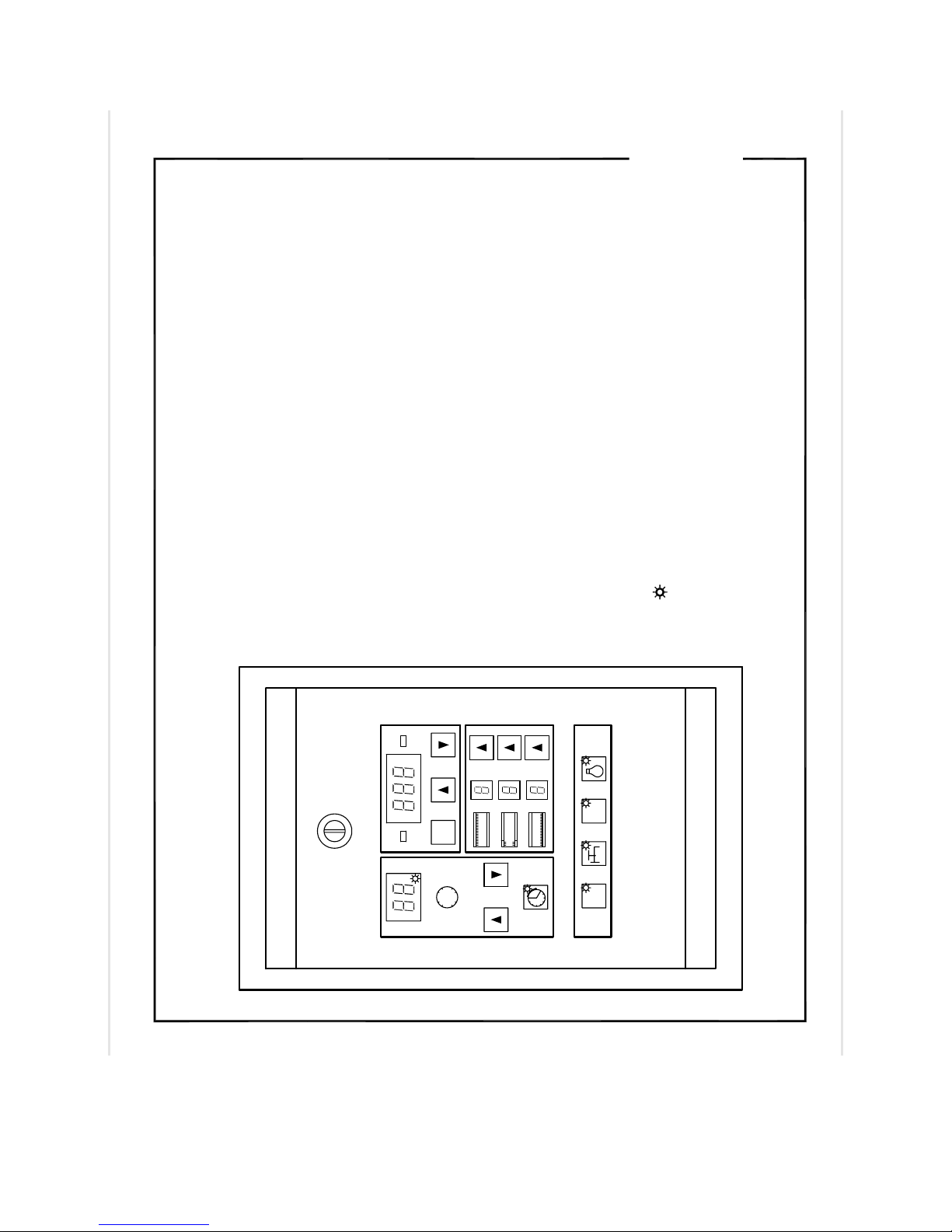
CONTROL
CONTROL
1− TEMPERATURE INDICATOR
2− TEMPERATURE DISPLAY
3− HEATING MODE
4− SET POINT ADJUSTMENT SWITCH
5− UP ARROW TEMPERATURE SETTING
6− DOWN ARROW TEMPERATURE SETTING
7− ELEMENT PERCENTAGE EFFICIENCY
8− ELEMENT PERCENTAGE EFFICIENCY SELECTOR
9− OVEN SECTION ON / OFF SWITCH
10− STEAM INJECTION SWITCH
11− ECONO MODE SELECTOR
Y
3
456
SET
39
6
12
TIMER
78
A
14 15
2
1
OK
ALARM
13
12− OVEN LIGHT ON / OFF SWITCH
13− COOKING TIMER DISPLAY
14− UP ARROW TIME ADJUSTMENT
C
B
16
A− TOP ELEMENT
15− DOWN ARROW TIME ADJUSTMENT
16− START / STOP TIMER SWITCH
ON ECO
9101112
− INDICATOR LIGHT
B− FRONT ELEMENT
C− BOTTOM ELEMENT
Page 10

A7
OPERATION OF THE OVEN
1. Turn the switch to the ‘ON” position.
• The display on the control panel will light.
2. Adjust the thermostat at the desired setting (see THERMOSTAT INSTRUCTIONS below).
NOTE: The digital display must be ON. If not, check the breaker on the inside side of the oven
near the electrical connectors and the main breaker of the oven.
3. Heat the unit until you reach the baking temperature (see preheating time below). The green
light "OK" on the thermostat will light. (If the digital display is on and the oven does not
produce heat, call for service.)
4. If you use the steam, be sure that the light indicator on the steam switch does not flash before
the next step.
5. Load the oven as fast as possible to avoid letting out too much heat.
6. Inject steam if desired.
7. Set the timer to the desired value and start it. (See timer adjustment on next page.)
NOTE: The timer does not shut off the oven at the end of its cycle, it simply activates the buzzer.
THERMOSTAT INSTRUCTIONS
IMPORTANT: Never heat the oven more than 650°F/350°C
To obtain a very good thermal stability, we use a digital temperature controller with thermocouple.
The thermostat controls the heat of the elements to the desired set point “SET”. This temperature
control also has the possibility to adjust the element efficiency percentage to obtain more or less heat
according to the used product. It is possible to increase or decrease the heat produced by the top
elements "A", in front near the door "B" and bottom "C" by using the controls 7 and 8 underneath the
thermostat. It is possible to adjust A, B and C from 0=0% to 11=100% for each element section.
Element "A" (top) base adjustment recommended for: bread 3 and pizza 3.
Element "B" (front) base adjustment recommended for: bread 4 and pizza 5.
Element "C" (bottom) base adjustment recommended for: bread 3 and pizza 5.
The temperature of the oven is always shown on the display of the thermostat and a red indicator
light "Y" indicates that the oven is in heating mode or a green indicator light "OK" indicates that the
desired temperature is reached.
To adjust the temperature, you have to press the "SET" button and hold it until the numbers flash.
Use the arrows to set the desired value. Press the ‘SET’ button to return to operating mode. The red
indicator light "Y" will light to indicate that the oven is on heating mode, when the temperature is
reached, the green indicator light "OK" will light up.
ECONO MODE
If you select the ECONO mode, the oven element will heat at 60% or 80% to save energy.
Press and hold the ECONO button to change form 60 % or 80%.
Page 11

A8
INSTRUCTIONS FOR OVEN
BAKING
ONLY BREAD OR PIZZA DOUGH CAN BE BAKED DIRECTLY ON THE STONES
The suggested temperature may be different depending on the type of dough. Always test with
your products before doing a complete production.
400oF/200°C (Croissants – Sweet doughs – Small rolls)
440oF/225°C (Baguette bread – round loaf - 10 oz bread and more)
N.B. Open the doors as little as possible. This will affect the baking.
COOKING TIMER
Set the baking time required with the push button # 16 on the timer.
Press and hold the button START/STOP # 16 until the display flashes. With the up and down
arrows, adjust the desired time for your cooking. Press the START/STOP #16 button again to return
to timer mode.
Example: 25 minutes = 25 (on green display)
After setting, push the START/STOP #16 button. The indicator light, on the START/STOP #16,
will flash and the green display will begin its countdown. When the time expires, the buzzer will
ring, push the START/STOP #16 button to stop the buzzer. If you want to add or take off time on
the green display during the baking, use the up and down arrows to re-adjust the time. When the time
expires, the timer will return to its initial time.
N.B. The timer is simply a reminder for the approximate duration of the baking time. It does not
stop the oven.
STEAM INJECTION
VERY IMPORTANT
STEAM INJECTION WILL ONLY WORK WHEN THE STEAM INDICATOR LIGHT OF
THE STEAM BUTTON IS OFF (NOT FLASHING).
To inject steam in the oven, press and hold the steam button one or two seconds.
N.B. Do not inject steam more than once each time you bake. Always be sure that the steam is
ready to use (the indicator light of the steam button does not flash) before loading the oven.
EUROPEAN STYLE PROOFER
To inject steam in the proofer, the thermostat must be set at 300ºC. When the pilot light of the
thermostat turns off at 300ºC (this indicates that the steam injection system is ready to use), press and
hold the steam button one or two seconds every 15 minutes to inject steam. The proofer cabinet only
has a steam injection system, it is not a warmer.
Page 12
A9
TROUBLESHOOTING
BEFORE CALLING FOR SERVICE
ANSWERS TO MOST FREQUENT QUESTIONS
Always cut off the main power before replacing any parts. Be careful with the water and
electric wire supply system when pulling the oven.
Control parts
Questions Solutions
The oven does not turn on.
Oven does not produce heat.
Uneven baking.
If steam device of the oven does not work
properly.
No light in the oven.
If there is no humidity in the proofer.
Remove the side panel of the oven by screwing
out the screws.
If the display does not light up, check the
breakers of the building and the oven, located
behind the panel on the right side facing the
oven.
If the red light (Y) does not light up.
Check if the thermostat is adjusted high enough
to turn on the pilot light.
Check breakers of the oven.
Check element efficiency percentage and adjust
to obtain more or less heat.
Check if the main water valve is opened.
Always be sure that the steam is ready to use
(the indicator light of the steam button does not
flash) before loading the oven.
Check breakers of the oven, located behind the
panel on the right side facing the oven.
Check if the light bulb is burned out.
Check if the pilot light of the proofer thermostat
has reached 300ºC. The pilot light must shut off
to indicate that the temperature is hot.
When you press the steam button, the light of the
steam button must turn on, if not, check breaker.
Page 13

A10
OVEN MAINTENANCE AND CLEANING
MAINTENANCE OF THE OVEN
• It is recommended to use a water filter and to clean or replace it regularly to avoid
accumulation of minerals inside the unit.
Step by step Recommendations
Clean the inside of the oven and the proofer.
Do not wash the stone with water and soap.
To clean the stone, remove it from the oven
and scrub with a scratch pad until you have
a clean and soft surface.
Clean the oven windows with products like
Brasso or equivalents. They are copper
cleaners but good for this use.
Clean the oven exterior with a stainless steel
cleaner.
We recommend and sell:
Dirt Buster III.
Action foam cleaner
Part number : NEB201
We recommend :
Scratch pad
We recommend and sell:
Glass cleaner
Part number : EXC300
We recommend and sell:
Stainless steel cleaner
Part number : NES201
Page 14

A11
FOR MORE INFORMATION,
PLEASE CONTACT OUR OFFICE:
DOYON EQUIPMENT INC.
1255, rue Principale
Linière, Qc, Canada G0M 1J0
Tel. : 1 (418) 685-3431
Canada : 1 (800) 463-1636
U.S. : 1 (800) 463-4273
FAX : 1 (418) 685-3948
Internet: http://www.doyon.qc.ca
E-Mail : doyon@doyon.qc.ca
Page 15

SECTION
B
DIMENSIONS
Page 16
44
HEIGHT
M
OD.
N
UM
OD.
M
N
UM
1TCN
1TCA
1TSA
1TSS
B1
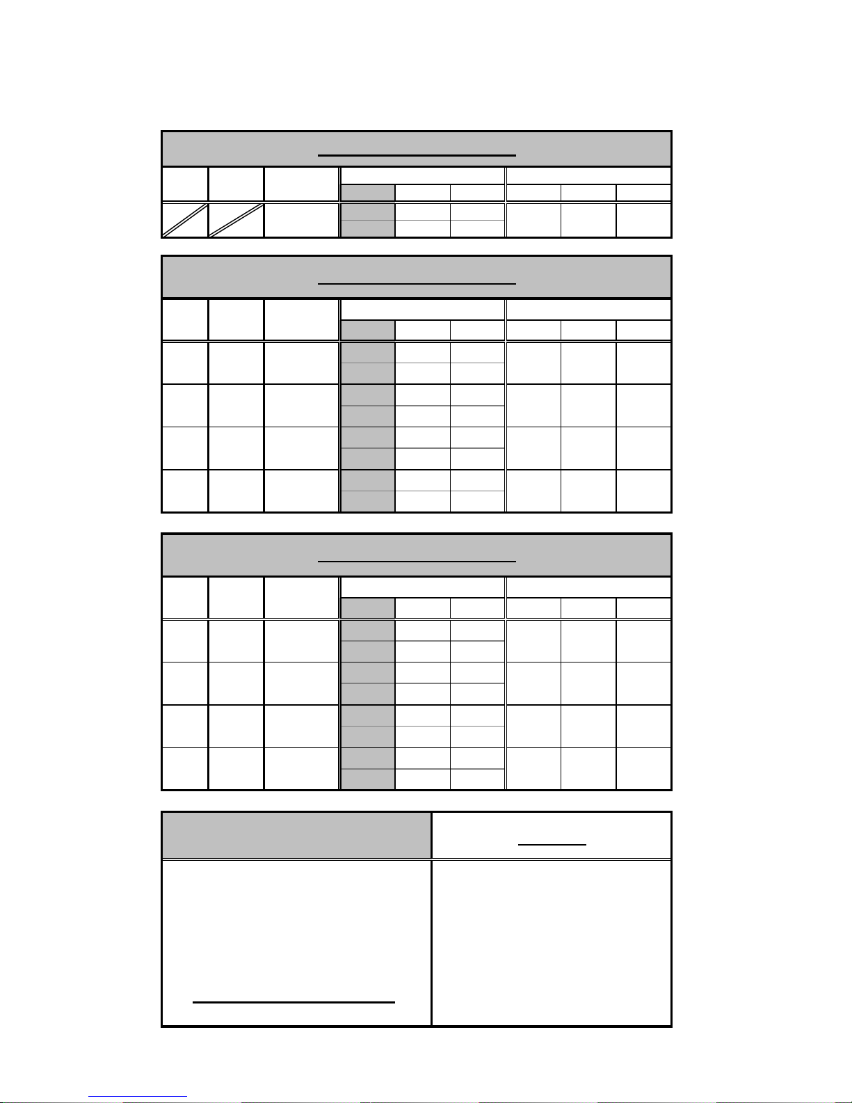
ARTISAN DECK OVEN 1T
TABLE OF DIMENSIONS "A"
I
P
AN
CAPAC. HEIGHT WIDTH DEPTH
T
C
OVER
YPE
E
XT. DIMENSIONS
5 34 1/2
(127) (876) (1 118)
TABLE OF DIMENSIONS "B"
P
AN
CAPAC.
1
1
1
1
T
YPE
N
ORMAL
H
IGHT
S
UPER
H
IGHT
UPER
S
S
UPER
H
IGHT
E
XT. DIMENSIONS
HEIGHT
12 7/8
(327)
14 7/8
WIDTH DEPTH
34 1/2
(876)
34 1/2
(378) (876)
16 7/8
34 1/2
(876)(429)
18 7/8
(479)
34 1/2
(876) (305)
46 1/4
(1 175)
46 1/4
(1 175)
46 1/4
(1 175)
46 1/4
(1 175)
NT. DIMENSIONS
-
I
NT. DIMENSIONS
HEIGHT WIDTH
6
(152)
8
(203)
10
(254)
12
WIDTH DEPTH
--
DEPTH
18 1/2
(470)
18 1/2
30
(762)
30
(470)30(762)
18 1/2
(470)
(762)
18 1/2
(470)30(762)
TABLE OF DIMENSIONS "C"
M
OD.
N
UM
1T
1T
1T
1T
P
AN
S
TACKED
CAPAC.
11
12
13
14
TABLE OF DIMENSIONS "D"
TOTAL HEIGHT OF OVEN
DIM "A"
(DIM "B" CN X QTY)
(DIM "B" CA X QTY)
+
(DIM "B" SA X QTY)
(DIM "B" SS X QTY)
DIM "C"
E
XT. DIMENSIONS
HEIGHT WIDTHCHAMBERS DEPTH
38
34 1/2 46
(965) (876) (1 168)
29
34 1/2 46
(737) (876) (1 168)
26
(660)
14
34 1/2
(876) (1 168)
34 1/2
46
(356) (876) (1 168)
FOR TOTAL HEIGHT,
ADD TOP HEIGHT, ALL
THE DECKS HEIGHT AND
BOTTOM STAND HEIGHT
I
NT. DIMENSIONS
HEIGHT WIDTH DEPTH
--
--
-
-
---
--46-
NOTES
TOTAL
Page 17

"A"
"B"
"B"
B2
34 1/2
ALARM
TIMER
ON ECO
ALARM
TIMER
ON ECO
OK Y
SET
OK Y
SET
1T_TABLE
"D"
"B"
"C"
ALARM
TIMER
ON ECO
OK Y
SET
10
5 1/8
7 1/2
1T_TABLE
Page 18

"A"
"B"
B3
40 3/4
46
1T_TABLE
44
3 1/4
"D"
"B"
"B"
5 1/8
"C"
7 1/2
1T_TABLE
Page 19

B4
1T_TABLE
ELECTRIC
INLET
Ø1 3/8"
"D"
"A"
"B"
"B"
"B"
3 1/2
2 1/2
34 1/2
3 1/4
5
1T_TABLE
"C"
5 1/8
WATER INLET
1/2" NPT
DRAIN
1/2" NPT
7 1/2
Page 20

M
HEIGHT
44
OD.
N
UM
M
OD.
N
UM
2TCN
2TCA
2TSA
2TSS
B5
ARTISAN DECK OVEN 2T
TABLE OF DIMENSIONS "A"
P
AN
CAPAC. HEIGHT WIDTH DEPTH
T
C
OVER
YPE
TABLE OF DIMENSIONS "B"
P
AN
CAPAC.
2
2
2
2
T
YPE
N
ORMAL
H
IGHT
S
UPER
H
IGHT
S
UPER
S
UPER
H
IGHT
E
XT. DIMENSIONS
5 56 1/4
(127) (1 429) (1 118)
E
XT. DIMENSIONS
HEIGHT
12 7/8
(327)
14 7/8
(378) (762)
16 7/8
18 7/8
(479) (953)30(762)
WIDTH DEPTH
56 1/4
(1 429)
56 1/4
46 1/4
(1 175)
46 1/4
(1 175)(1 429)
56 1/4
(1 429)(429)
56 1/4
(1 429) (305)
46 1/4
(1 175)
46 1/4
(1 175)
I
NT. DIMENSIONS
-
I
NT. DIMENSIONS
HEIGHT WIDTH
6
(152)
8
(203)
10
(254)
12
WIDTH DEPTH
--
DEPTH
37 1/2
(953)
37 1/2
30
(762)
30
(953)
37 1/2
(953)
30
(762)
37 1/2
TABLE OF DIMENSIONS "C"
S
M
OD.
N
UM
2T
2T
2T
2T
P
AN
CAPAC.
21
22
23
24
TACKED
CHAMBERS DEPTH
TABLE OF DIMENSIONS "D"
TOTAL HEIGHT OF OVEN
DIM "A"
(DIM "B" CN X QTY)
(DIM "B" CA X QTY)
+
(DIM "B" SA X QTY)
(DIM "B" SS X QTY)
DIM "C"
E
XT. DIMENSIONS
HEIGHT WIDTH
38
56 1/4
46
(965) (1 429) (1 168)
29
56 1/4
46
(737) (1 429) (1 168)
26
(660)
14
(356)
56 1/4
46
(1 429) (1 168)
56 1/4
(1 429) (1 168)
FOR TOTAL HEIGHT,
ADD TOP HEIGHT, ALL
THE DECKS HEIGHT AND
BOTTOM STAND HEIGHT
I
NT. DIMENSIONS
HEIGHT WIDTH DEPTH
--
--
-
-
---
--46-
NOTES
TOTAL
Page 21

"A"
"B"
"B"
B6
56 1/4
2T_TABLE
OK Y
ALARM
SET
TIMER
ON ECO
OK Y
ALARM
SET
TIMER
ON ECO
"D"
"B"
"C"
ALARM
TIMER
ON ECO
OK Y
SET
10
5 1/8
7 1/2
2T_TABLE
Page 22

"A"
"B"
B7
44
40 3/4
46
2T_TABLE
3 1/4
"D"
"B"
"B"
5 1/8
"C"
7 1/2
2T_TABLE
Page 23

B8
2T_TABLE
ELECTRIC
INLET
Ø1 3/8"
"D"
"A"
"B"
"B"
"B"
3 1/2
2 1/2
56 1/4
3 1/4
5
2T_TABLE
"C"
WATER INLET
1/2" NPT
5 1/8
DRAIN
1/2" NPT
7 1/2
Page 24

44
HEIGHT
M
OD.
N
UM
M
OD.
UM
N
3TCN
3TCA
3TSA
3TSS
B9
ARTISAN DECK OVEN 3T
TABLE OF DIMENSIONS "A"
I
P
AN
CAPAC. HEIGHT WIDTH DEPTH
T
C
OVER
YPE
E
XT. DIMENSIONS
575
(127) (1 905) (1 118)
TABLE OF DIMENSIONS "B"
P
AN
CAPAC.
3
3
3
3
T
YPE
N
ORMAL
H
IGHT
S
UPER
IGHT
H
UPER
S
S
UPER
H
IGHT
E
XT. DIMENSIONS
HEIGHT
12 7/8
(327)
(378) (762)
16 7/8
18 7/8
(479)
WIDTH DEPTH
75
(1 905)
75
46 1/4
(1 175)
46 1/4
(1 175)(1 905)
75
(1 905)(429)
75
(1 905) (305)
46 1/4
(1 175)
46 1/4
(1 175)
NT. DIMENSIONS
-
I
NT. DIMENSIONS
6
8
(203)
10
(254)
12
WIDTH DEPTH
--
DEPTHHEIGHT WIDTH
56
(1 422)(152)
56
30
(762)
3014 7/8
(1 422)
56
(1 422)
30
(762)
56
(1 422)30(762)
TABLE OF DIMENSIONS "C"
M
OD.
N
UM
P
CAPAC.
3T
3T
3T
3T
S
AN
3
TACKED
CHAMBERS DEPTH
1
32
33
34
TABLE OF DIMENSIONS "D"
TOTAL HEIGHT OF OVEN
DIM "A"
(DIM "B" CN X QTY)
(DIM "B" CA X QTY)
+
(DIM "B" SA X QTY)
(DIM "B" SS X QTY)
DIM "C"
E
XT. DIMENSIONS
HEIGHT WIDTH
38
75
46
(965) (1 905) (1 168)
29
75
46
(737) (1 905) (1 168)
26
(660)
14
(356)
75
(1 905) (1 168)
75
(1 905) (1 168)
46
FOR TOTAL HEIGHT,
ADD TOP HEIGHT, ALL
THE DECKS HEIGHT AND
BOTTOM STAND HEIGHT
I
NT. DIMENSIONS
HEIGHT WIDTH DEPTH
--
--
-
-
-
--
--46-
NOTES
TOTAL
Page 25

"A"
"B"
"B"
B10
75
3T_TABLE
OK Y
ALARM
SET
TIMER
ON ECO
OK Y
ALARM
SET
TIMER
ON ECO
"D"
"B"
"C"
ALARM
TIMER
ON ECO
OK Y
SET
10
5 1/8
7 1/2
3T_TABLE
Page 26

"A"
"B"
B11
40 3/4
46
3T_TABLE
44
3 1/4
"D"
"B"
"B"
5 1/8
"C"
7 1/2
3T_TABLE
Page 27

B12
3T_TABLE
ELECTRIC
INLET
Ø1 3/8"
"A"
"B"
"B"
"D"
"B"
3 1/2
2 1/2
75
3 1/4
5
"C"
3T_TABLE
WATER INLET
1/2" NPT
5 1/8
DRAIN
1/2" NPT
7 1/2
Page 28

SECTION
E
COMPONENT PARTS
Page 29

11
E1
10
1T_TABLE
OK Y
ALARM
SET
TIMER
ONECO
OK Y
ALARM
SET
TIMER
9
ON ECO
3
5 6
1 2
8
OK Y
ALARM
SET
TIMER
ON ECO
10
4
7
1T_TABLE
Page 30

E2
Front view
Item Part Number Description Quantity
1 MPA168 LOCKING CASTER (FRONT OF THE OVEN) 2
& MPA167 NON LOCKING CASTER (BACK OF THE OVEN) 2
2 PA0341C LEGS WITHOUT CASTERS (25") 4
OR PA0342C LEGS WITHOUT CASTERS (16") 4
OR PA0343C LEGS WITHOUT CASTERS (13") 4
OR PA0344C LEGS WITHOUT CASTERS (1") 4
3 PA009CN BLACK KNOB FOR STEAM DAMPER (CN CHAMBER) 1
OR PA009CA BLACK KNOB FOR STEAM DAMPER (CA CHAMBER) 1
OR PA009SA BLACK KNOB FOR STEAM DAMPER (SA CHAMBER) 1
OR PA009SS BLACK KNOB FOR STEAM DAMPER (SS CHAMBER) 1
4 MPP089 DOOR HANDLE 1
& FMB601 DIA. 5/16” WASHER 1
& AZRB200 DIA. 5/16” LOCK WASHER 1
& FMB552 M8 NUT 1
& MPP211 ALLUMINIUM CAP NUT 1
5 PA023-1TCN DOOR FRAME INCLUDES BOTH GLASSES (NO HANDLES) 1TCN 1
OR PA023-1TCA DOOR FRAME INCLUDES BOTH GLASSES (NO HANDLES) 1TCA 1
OR PA023-1TSA DOOR FRAME INCLUDES BOTH GLASSES (NO HANDLES) 1TSA 1
OR PA023-1TSS DOOR FRAME INCLUDES BOTH GLASSES (NO HANDLES) 1TSS 1
6 MPV001 EXTERIOR TINTED DOOR GLASS (18 7/16"x4 3/4"x1/4") 1TCN 1
OR MVP003 EXTERIOR TINTED DOOR GLASS (18 7/16"x6 3/4"x1/4") 1TCA 1
OR MVP005 EXTERIOR TINTED DOOR GLASS (18 7/16"x8 3/4"x1/4") 1TSA 1
OR MVP007 EXTERIOR TINTED DOOR GLASS (18 7/16"x10 3/4"x1/4") 1TSS 1
7 MEC024 MAIN SWITCH KNOB 1
& MEC031 MAIN SWITCH LIGHT’S SOCKET 1
& MEC034 MAIN SWITCH CONTACT (NO) 1
& MER061
8 MEC008 CONTROL PANEL 1
& MEC066 OVEN THERMOCOUPLE TYPE K 1
& MEC067 STEAM THERMOCOUPLE TYPE K 1
9 MPR037 STONE DECK FOR 1T (PINK) 1
OR PA021R-1T
10 MVP002 INTERIOR NON TINTED DOOR GLASS (15 1/4"x4 3/4"x1/4") 1TCN 1
OR MVP004 INTERIOR NON TINTED DOOR GLASS (15 1/4"x6 3/4"x1/4") 1TCA 1
OR MVP006 INTERIOR NON TINTED DOOR GLASS (15 1/4"x8 3/4"x1/4") 1TSA 1
OR MVP008 INTERIOR NON TINTED DOOR GLASS (15 1/4"x10 3/4"x1/4") 1TSS 1
11 MPR021 1
1T ARTISAN DECK OVEN (FRONT VIEW)
Page 31

E3
1T_TABLE
4 6 7 8 9 10
3
2
1
5
11
C40 C10 C6 C10
1 : ON1 : ON 1 : ON 1 : ON1 : ON1 : ON
12 13
1 : ON1 : ON
1T_TABLE
Page 32

E4
Side view
Item Part Number Description Quantity
1 MER001 ELEMENT BLOCK 208V – 240V (1T) 12
OR MER001A ELEMENT BLOCK 480V (1T) 12
2 MER011 LIGHT BULB TYPE MR16 1
& MER019 SOCKET FOR 20W LIGHT BULB 1
3 MER068 TRANSFORMATOR 240V > 12V, 24V 1
& TRANSFORMATOR 240 > 24 IF WATER SOLENOID VALVE IS 24 VAC 1
4 TERMINAL BLOCK FOR BUZZER 2
5 MEC042 1
& MEC042B 1
6 TERMINAL BLOCK FOR CONTROL 6
7 MEC062 CONTACTO FOR OVEN ELEMENTS 3
8 MEC062 CONTACTOR FOR STEAM ELEMENT 1
9 MEP054 TRIPLE BREAKER 40A 1
10 DOUBLE BREAKER 10A 1
11 MEP005 DOUBLE BREAKER 6A 1
12 MEP003 SINGLE BREAKER 10A 1
13 MEL159 TERMINAL BLOCK 1
& MEL157 GROUND TERMINAL BLOCK 1
1T ARTISAN DECK OVEN (SIDE VIEW)
Page 33

E5
1T_TABLE
3
1
2
1T_TABLE
Page 34

E6
Back view
Item Part Number Description Quantity
1 STEAM GENERATOR BOX ASSY 1
& WATER INJECTOR 1
2 MER059 ELEMENT 600W 230V FOR THE STEAM GENERATOR 2
OR MER027A ELEMENT 600W 40V FOR STEAM 2
3 MEC014A SOLENOID VALVE 24 VAC 50 Hz 27 VA 1
OR MEC014B SOLENOID VALVE 12 VAC 50 Hz 27 VA 1
1T ARTISAN DECK OVEN (BACK VIEW)
Page 35

11
TABLE
E7
2T_
OK Y
ALARM
SET
TIM
ER
ON ECO
OK Y
ALARM
SET
9
10
TIMER
ON ECO
8
OK Y
ALARM
SET
TIMER
ON ECO
10
5 6
4
3
1
2
7
2T_TABLE
Page 36

E8
Front view
Item Part Number Description Quantity
1 MPA168 LOCKING CASTER (FRONT OF THE OVEN) 2
& MPA167 NON LOCKING CASTER (BACKOF THE OVEN) 2
2 PA0341C LEGS WITHOUT CASTERS (25") 4
OR PA0342C LEGS WITHOUT CASTERS (16") 4
OR PA0343C LEGS WITHOUT CASTERS (13") 4
OR PA0344C LEGS WITHOUT CASTERS (1") 4
3 PA009CN BLACK KNOB FOR STEAM DAMPER (CN CHAMBER) 1
OR PA009CA BLACK KNOB FOR STEAM DAMPER (CA CHAMBER) 1
OR PA009SA BLACK KNOB FOR STEAM DAMPER (SA CHAMBER) 1
OR PA009SS BLACK KNOB FOR STEAM DAMPER (SS CHAMBER) 1
4 MPP089 DOOR HANDLE 2
& FMB601 DIA. 5/16” WASHER
& AZRB200 DIA. 5/16” LOCK WASHER
& FMB552 M8 NUT
& MPP211 ALLUMINIUM CAP NUT
5 PA023-2TCN DOOR FRAME INCLUDES BOTH GLASSES (NO HANDLES) 2TCN 1
OR PA023-2TCA DOOR FRAME INCLUDES BOTH GLASSES (NO HANDLES) 2TCA 1
OR PA023-2TSA DOOR FRAME INCLUDES BOTH GLASSES (NO HANDLES) 2TSA 1
OR PA023-2TSS DOOR FRAME INCLUDES BOTH GLASSES (NO HANDLES) 2TSS 1
6 MPV009 EXTERIOR TINTED DOOR GLASS (37 3/16"x4 3/4"x1/4") 2TCN 1
OR MVP011 EXTERIOR TINTED DOOR GLASS (37 3/16"x6 3/4"x1/4") 2TCA 1
OR MVP013 EXTERIOR TINTED DOOR GLASS (37 3/16"x8 3/4"x1/4") 2TSA 1
OR MVP015 EXTERIOR TINTED DOOR GLASS (37 3/16"x10 3/4"x1/4") 2TSS 1
7 MEC024 MAIN SWITCH KNOB 1
& MEC031 MAIN SWITCH LIGHT’S SOCKET 1
& MER061
& MEC034 MAIN SWITCH CONTACT (NO) 1
8 MEC008 CONTROL PANEL 1
& MEC066 OVEN THERMOCOUPLE TYPE K 1
& MEC067 STEAM THERMOCOUPLE TYPE K 1
9 MPR037 STONE DECK FOR 2T (PINK) 1
OR PA021R-2T
10 MVP010 INTERIOR NON TINTED DOOR GLASS (34"x4 3/4"x1/4") 2TCN 1
OR MVP012 INTERIOR NON TINTED DOOR GLASS (34"x6 3/4"x1/4") 2TCA 1
OR MVP014 INTERIOR NON TINTED DOOR GLASS (34"x8 3/4"x1/4") 2TSA 1
OR MVP016 INTERIOR NON TINTED DOOR GLASS (34"x10 3/4"x1/4") 2TSS 1
11 MPR021 1
2T ARTISAN DECK OVEN (FRONT VIEW)
Page 37

E9
TABLE
2T_
3
2
1
4
678 9 10
5
11
C40 C10 C6 C10
1 : ON1 : ON 1 : ON 1 : ON1 : ON1 : ON
12 13
1 : ON1 : ON
2T_TABLE
Page 38

E10
Side view
Item Part Number Description Quantity
1 MER006 ELEMENT BLOCK 208V – 240V (2T) 12
OR MER006A ELEMENT BLOCK 480V (2T) 12
2 MER011 LIGHT BULB TYPE MR16 1
& MER019 SOCKET FOR 20W LIGHT BULB 1
3 MER068 TRANSFORMATOR 120V > 12V, 24V 1
4 TERMINAL BLOCK FOR BUZZER 2
5 MEC042 1
& MEC042B 1
6 TERMINAL BLOCK FOR CONTROL 6
7 MEC062 CONTACTOR OMRON J7K-CM FOR OVEN ELEMENTS 3
8 MEC062 CONTACTOR FOR STEAM ELEMENT 1
9 MEP054 TRIPLE BREAKER 40A 1
10 DOUBLE BREAKER 10A 1
11 MEP005 DOUBLE BREAKER 6A 1
12 MEP003 SINGLE BREAKER 10A 1
13 MEL159
& M TERMINAL BLOCK 1
2T ARTISAN DECK OVEN (SIDE VIEW)
Page 39

E11
3
2T_TABLE
1
2
2T_TABLE
Page 40

E12
Back view
Item Part Number Description Quantity
1
2 MER059 ELEMENT 600W 230V FOR STEAM GENERATOR 2
3 MEC014A SOLENOID VALVE 24 VAC 50 Hz 27 VA 1
OR MEC014B SOLENOID VALVE 12 VAC 50 Hz 27 VA 1
2T ARTISAN DECK OVEN (BACK VIEW)
Page 41

11
E13
3T_TABLE
OK Y
AL
AR
M
SE
T
TIMER
ON ECO
OK Y
ALARM
SET
9
10
TIMER
ON ECO
5 6
4
3
1 2
ALARM
TIMER
ON ECO
OK Y
SET
10
8
7
3T_TABLE
Page 42

E14
Front view
Item Part Number Description Quantity
1 MPA168 LOCKING CASTER (FRONT OF THE OVEN) 2
& MPA167 NON LOCKING CASTER (BACKOF THE OVEN) 2
2 PA0341C LEGS WITHOUT CASTERS (25") 4
OR PA0342C LEGS WITHOUT CASTERS (16") 4
OR PA0343C LEGS WITHOUT CASTERS (13") 4
OR PA0344C LEGS WITHOUT CASTERS (1") 4
3 PA009CN BLACK KNOB FOR STEAM DAMPER (CN CHAMBER) 1
OR PA009CA BLACK KNOB FOR STEAM DAMPER (CA CHAMBER) 1
OR PA009SA BLACK KNOB FOR STEAM DAMPER (SA CHAMBER) 1
OR PA009SS BLACK KNOB FOR STEAM DAMPER (SS CHAMBER) 1
4 MPP089 DOOR HANDLE 1
5 PA0233TCN DOOR FRAME INCLUDES BOTH GLASSES (NO HANDLES) 3TCN 1
OR PA0233TCA DOOR FRAME INCLUDES BOTH GLASSES (NO HANDLES) 3TCA 1
OR PA0233TSA DOOR FRAME INCLUDES BOTH GLASSES (NO HANDLES) 3TSA 1
OR PA0233TSS DOOR FRAME INCLUDES BOTH GLASSES (NO HANDLES) 3TSS 1
6 MPV017 EXTERIOR TINTED DOOR GLASS (55 5/8”x4 ¾”x1/4”) 3TCN 1
OR MVP019 EXTERIOR TINTED DOOR GLASS (55 5/8”x6 ¾”x1/4”) 3TCA 1
OR MVP021 EXTERIOR TINTED DOOR GLASS (55 5/8”x8 ¾”x1/4”) 3TSA 1
OR MVP023 EXTERIOR TINTED DOOR GLASS (55 5/8”x10 ¾”x1/4”) 3TSS 1
7 MEC024 MAIN SWITCH KNOB 1
& MEC031 MAIN SWITCH LIGHT 1
& MEC034 MAIN SWITCH CONTACT (NO) 1
8 MEC008 CONTROL PANEL 1
& MEC066 OVEN THERMOCOUPLE TYPE K 1
& MEC067 STEAM THERMOCOUPLE TYPE K 1
9 MPR044 STONE DECK FOR 3T 1
10 MVP018 INTERIOR NON TINTED DOOR GLASS (52 3/8”x4 ¾”x1/4”) 3TCN 1
OR MVP020 INTERIOR NON TINTED DOOR GLASS (52 3/8”x6 ¾”x1/4”) 3TCA 1
OR MVP022 INTERIOR NON TINTED DOOR GLASS (52 3/8”x8 ¾”x1/4”) 3TSA 1
OR MVP024 INTERIOR NON TINTED DOOR GLASS (52 3/8”x10 ¾”x1/4”) 3TSS 1
11 MPR021 1
3T ARTISAN DECK OVEN (FRONT VIEW)
Page 43

E15
3T_TABLE
6
3
5
4
2
1
7
8 9 10
11
C40 C10 C6 C10
1 : ON1 : ON 1 : ON 1 : ON1 : ON1 : ON
12 13
1 : ON1 : ON
3T_TABLE
Page 44

E16
Side view
Item Part Number Description Quantity
1 MER002 ELEMENT BLOCK 208V – 240V (2T) 12
OR MER002A ELEMENT BLOCK 480V (2T) 12
2 MER011 LIGHT BULB TYPE MR16 1
& MER019 SOCKET FOR 20W LIGHT BULB 1
3 TRANSFORMATOR 120V > 12V, 24V 1
4 TERMINAL BLOCK FOR BUZZER 2
5 MEC042 1
& MEC042B 1
6 TERMINAL BLOCK FOR CONTROL 6
7 MEC069 CONTACTOR OMRON J7K-CM FOR OVEN ELEMENTS 3
8 MEC062 CONTACTOR FOR STEAM ELEMENT 1
9 TRIPLE BREAKER 40A 1
10 DOUBLE BREAKER 10A 1
11 MEP005 DOUBLE BREAKER 6A 1
12 MEP003 SINGLE BREAKER 10A 1
13 TERMINAL BLOCK 1
3T ARTISAN DECK OVEN (SIDE VIEW)
Page 45

E17
3T_TABLE
1
3
2
3T_TABLE
Page 46

E18
Back view
Item Part Number Description Quantity
1
2 MER059 ELEMENT 600W 230V FOR STEAM GENERATOR 2
3 MEC014A SOLENOID VALVE 24 VAC 50 Hz 27 VA 1
OR MEC014B SOLENOID VALVE 12 VAC 50 Hz 27 VA 1
3T ARTISAN DECK OVEN (BACK VIEW)
Page 47

SECTION
G
ELECTRIC SCHEMATICS
Page 48

G1
250VA
12V
q1
220V
123
7085
PAINEL INTEGRADO
A2
g1
b1
b4
3
45896
7
11
10
MALHA
PARA
OUTROS
(CASA)
12
16
17
1819
−
+
24V
13
14
15
A1
VAPOR
c4
A2
LAR
A1
c3
A2
A1
PORTAc1
A2
A1
TECTO
c2
HIGH LIMIT
BUZZER
f1
−
+
−
+
VAPOR
SONDA
SONDA
FORNOS
d1
208 24A 24A 24A 8.6W
b3
L1L2L3
1 / 1
1T_3PH
1T
1T ARTISAN STONE OVEN
220 29A 29A 29A 10.3W
23/09/04 M. FAUCHER 2
240 32A 32A 32A 12.3W
NONE
TOTAL POWER: 3 PH. 60 Hz
k1
k2
b2
b1
A1
A2
VAPOR
c4
VAPORISADOR
RESISTENCIAS
A2
LAR
A1
c3
A2
A1
TECTO
c2
A2
A1
PORTA
c1
j1
R2
R1
R2
R1
j1
j1
R2
R1
R2
R1
j1
j1
R2
R1
R2
R1
j1
j1
R2
R1
R2
R1
j1
j1
R2
R1
R2
R1
j1
j1
R2
R1
R2
R1
j1
Page 49

G2
250VA
12V
q1
220V
123
7085
PAINEL INTEGRADO
A2
A1
g1
b1
b4
3
45896
7
11
10
MALHA
PARA
OUTROS
12
1819 1716
(CASA)
−
+
24V
151413
VAPOR
c4
A2
A1
c3 LAR
A2
A1
PORTAc1
A2
A1
TECTO
c2
HIGH LIMIT
BUZZER
f1
−
+
−
+
SONDA
SONDA
VAPOR
d1
FORNOS
208 41A 41A 41A 14W
b3
L3
L1L2
1 / 1
2T_3PH
2T
2T ARTISAN STONE OVEN
220 43A 43A 43A 15.6W
23/09/04 M. FAUCHER 1
240 47A 47A 47A 18.6W
NONE
TOTAL POWER: 3 PH. 60 Hz
k1
k2
b2
b1
A1
A2
VAPOR
c4
VAPORISADOR
RESISTENCIAS
A2
LAR
A1
c3
A2
A1
TECTO
c2
A2
A1
PORTA
c1
j1
R2
R1
R2
R1
j1
j1
R2
R1
R2
R1
j1
j1
R2
R1
R2
R1
j1
j1
R2
R1
R2
R1
j1
j1
R2
R1
R2
R1
j1
j1
R2
R1
R2
R1
j1
Page 50

G3
250VA
12V
q1
220V
123
7085
PAINEL INTEGRADO
A2
g1
b1
b4
3
45896
7
11
10
MALHA
PARA
OUTROS
12
1819 17 16
(CASA)
−
+
24V
151413
A1
VAPOR
c4
A2
A1
c3 LAR
A2
A1
PORTAc1
A2
A1
TECTO
c2
HIGH LIMIT
BUZZER
f1
−
+
−
+
SONDA
SONDA
VAPOR
d1
FORNOS
208 56A 56A 56A 19.5W
b3
k1
k2
b2
A1
A2
VAPOR
c4
VAPORISADOR
RESISTENCIAS
j1
R1
L3
L1L2
j1
R2
R2
R1
1 / 1
3T_3PH
3T
3T ARTISAN STONE OVEN
220 59.5A 59.5A 59.5A 21.8W
23/09/04 M. FAUCHER 3
240 65A 65A 65A 26W
NONE
TOTAL POWER: 3 PH. 60 Hz
R2
R1
b1
A1
A1
A1
LAR
c3
TECTO
c2
PORTA
c1
A2
A2
A2
j1
j1
R2
R1
R2
R1
j1
j1
R2
R1
R2
R1
j1
R2
R1
j1
j1
R2
R1
R2
R1
j1
j1
R2
R1
R2
R1
j1
Page 51

G4
1 / 1
250VA
12V
q1
220V
123
7085
PAINEL INTEGRADO
g1
b1
b4
3
45896
7
11
10
MALHA
PARA
OUTROS
12
1819 1716
(CASA)
−
+
24V
13
14
15
6A
b3
A2
A1
VAPOR
c4
A2
A1
c3 LAR
A2
A1
PORTAc1
A2
A1
TECTO
c2
HIGH LIMIT
BUZZER
f1
−
+
−
+
SONDA
SONDA
VAPOR
FORNOS
d1
10A
b3
STEAM
PROOFER
d1
220V
HIGH LIMIT
12V
220V
STEAM
1T ARTISAN STONE OVEN
1KW
1.1KW
220 29A 29A 29A 10.3
L1L2L3
208 27.5A 27.5A 27.5A 9.2
8/04/05 M. FAUCHER 1
1.3KW
240 32A 32A 32A 12.3
1T_OP_C2
1T
OVEN / PROOFER
NONE
TOTAL POWER: 3 PH. 60 Hz
k2
k1
b2
A2
A1
VAPOR
c4
VAPORISADOR
RESISTENCIAS
j1
R2
R1
j1
R2
R1
R2
R1
b1
A2
LAR
A1
c3
A2
A1
TECTO
c2
A2
A1
PORTA
c1
j1
j1
R2
R1
R2
R1
j1
j1
R2
R1
R2
R1
j1
R2
R1
j1
j1
R2
R1
R2
R1
j1
j1
R2
R1
R2
R1
j1
Page 52

LIMITED WARRANTY
(Continental United States Of America And Canada Only)
Doyon Equipment Inc. guarantees to the original purchaser only that its product are free of defects in
material and workmanship, under normal use.
This warranty does not cover any light bulbs, thermostat calibration or defects due to or resulting
from handling, abuse, misuse, nor shall it extend to any unit from which the serial number has been
removed or altered, or modifications made by unauthorized service personnel or damage by flood,
fire or other acts of God. Nor will this warranty apply as regards to the immersion element damaged
by hard water.
The extent of the manufacturer’s obligation under this warranty shall be limited to the replacement
or repair of defective parts within the warranty period. The decision of the acceptance of the
warranty will be made by Doyon Equipment service department, which decision will be final.
The purchaser is responsible for having the equipment properly installed, operated under normal
conditions with proper supervision and to perform periodic preventive maintenance.
If any parts are proven defective during the period of one year from date of purchase, Doyon
Equipment Inc. hereby guarantees to replace, without charge, F.O.B. Linière, Quebec, Canada, such
part or parts.
Doyon Equipment Inc. will pay the reasonable labor charges in connection with the replacement
parts occurring within one year from purchase date. Travel over 50 miles, holiday or overtime
charges are not covered. After one year from purchase date, all labor and transportation charges in
connection with replacement parts will be the purchaser’s responsibility.
Doyon Equipment Inc. does hereby exclude and shall not be liable to purchaser for any
consequential or incidental damages including, but not limited to, damages to property, damages for
loss of use, loss of time, loss of profits or income, resulting from any breach or warranty.
In no case, shall this warranty apply outside Canada and continental United States unless the
purchaser has a written agreement from Doyon Equipment Inc.
 Loading...