

Page 1
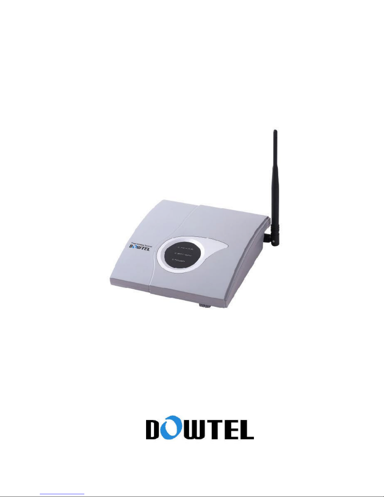
WS-2100/4100 Manual
Page 2

WS-2100/4100 Operating Manual
2
CONTENTS
About Our FWT
1. Before Using Your Terminal
1.1 Unpacking
1.2 Name and Function of Each Part
1.3 Sound & Tone
1.4 Safety Instructions
2. Installations
2.1 General Installation
2.2 Installation For the Data Service
2.3 Installing the Wall Bracket
3. Basic Functions
3.1 Power On
3.1.1 How to Operate with External Power
3.1.2 How to Operate with Built-in Battery
3.2 Power Off
3.3 Making a Call
3.3.1 General Method
3.3.2 Making a Call Using the Speed Dial Function
3.3.3 Making a Call Using the Redial Function
3.4 Receiving an Incoming Call
3.4.1 On-Hook State
3.4.2 Off-Hook State
3.5 How to Use Analog G3 Fax
3.5.1 To Send a Document by Fax
3.5.2 To Receive a Document by Fax
3.6 Data Service
3.6.1 Setting Data Service Receiving Mode
4. Supplementary Functions
4.1 Call Functions
4.1.1 Speed Dial
4.1.2 Hot Line Function
4.2 Phone Book
4.2.1 Storing P hone Numbers
Page 3

WS-2100/4100 Operating Manual
3
4.2.2 Deleting P hone Numbers
4.3 Additional Function
4.3.1 Alarm Reminder
4.3.2 Handset Volume Control
4.3.3 Setting the Voice Privacy Function
4 .3.4 Serial Baud Rate Setting
4.4 Lock
4.4.1 Outgoing Lock
4.4.2 Changing Lock Code (User’s Password)
4.4.3 Reset as Default
4.5. Ma intenance Setup
4.5.1 CLIP Setting
4.5.2 Analog G3 Fax Setting
4.5.3 Default Data Rate Setting
4.5.4 Ringer Frequency & Cadence Control
4.5.5 Dial Tone Frequency Control
4.5.6 Waiting Tone Frequency Control
4.5.7 Default Vocoder Selection
4.5.8 Auto Dial Send Time Control
4.5.9 PCO Frequency Setting
4.5.10 PRL select (Only applicable to WS -2100)
4.6 System Parameter Setup
4.6.1 Phone Number(MIN) Input
4.6.2 Directory Number Input
4.6.3 Country Code (MCC) Input
4.6.4 Network Code (MNC) Input
4.6.5 Slot Cycle Index Input
4.6.6 A-Key Input
4.6.7 Channel Input & Delete (Only applicable to WS -2100)
4.6.8 SID/NID Input & Delete
4.6.9 System Preference Setting
APPENDIX
1. Summary Table - S upplementary Functions
2. Technical Specification
3. Troubleshooting
4. Feature Code Table
5. Maintenance code Table
6. System Parameter Setup Table
Page 4

WS-2100/4100 Operating Manual
4
About Dowtel FWT
(1) WS-2100/4100 both have a practical but elegant design. It can be used at office or home.
WS-2100/4100 also offers many useful features and technological advantages.
(2) WS-2100/4100 has Versatile Installation Options
(3) WS-2100/4100 looks perfect on your desk in the office. It can also be installed on any wall in your
office or home thanks to the wall-mount kit that comes with the unit.
(4) WS-2100/4100 offers its users superior voice quality through its use of QCELP EVRC Vocoder.
(5) WS-2100/4100 owners can easily adjust the volume of the handset with the volume control, and set
the volume at an optimal level.
(6) Tricolor LEDs visually indicate the status of the terminal.
(7)The owner can control who can access, and use the terminal with the Outgoing Lock function.
(8) Simple and quick transmission of the stored number in the phone book with One-Touch and Two Touch Dial.
(9) The Hotline Call function allows the most frequently used number to be automatically connected
when a user picks up the handset.
(10) Various sounds and LED functions provide audio and visual alerts for Low Battery, Air Link Cut-Off
and Incorrect Use
(1 1) A connected terminal allows DTMF transmission for ARS connection.
(12) Connect WS-2100/4100 with your PC for data transmission and PC fax communication.
(13) The Voice Privacy function ensures against illegal phone tapping can be prevented.
(14) The Authentication Key function prevents the owner’s phone number from being cloned
by others.
(15) Caller I.D function lets you know who is calling you.
(16) WS-2100/4100 user interface menu driver is easy to use.
(17) G3 Fax (Optional) service is supported for analog environment.
(18) The Pay Phone Interface allows WS-2100/4100 to work as a payphone.
(19) This terminal supports High Speed Packet Data using MSM 5000 series chip.
Page 5
WS-2100/4100 Operating Manual
5
1. Before Using Your Terminal
This manual contains chapters on terminal introduction, installation method, basic directions,
feature code and the technical standard, troubleshooting for potential problems. Please read
through the contents of this manual carefully before using this product.
[Note]
If you have any questions or think that the product maybe defective, please contact the store
where the unit was purchased.
1.1 Unpacking
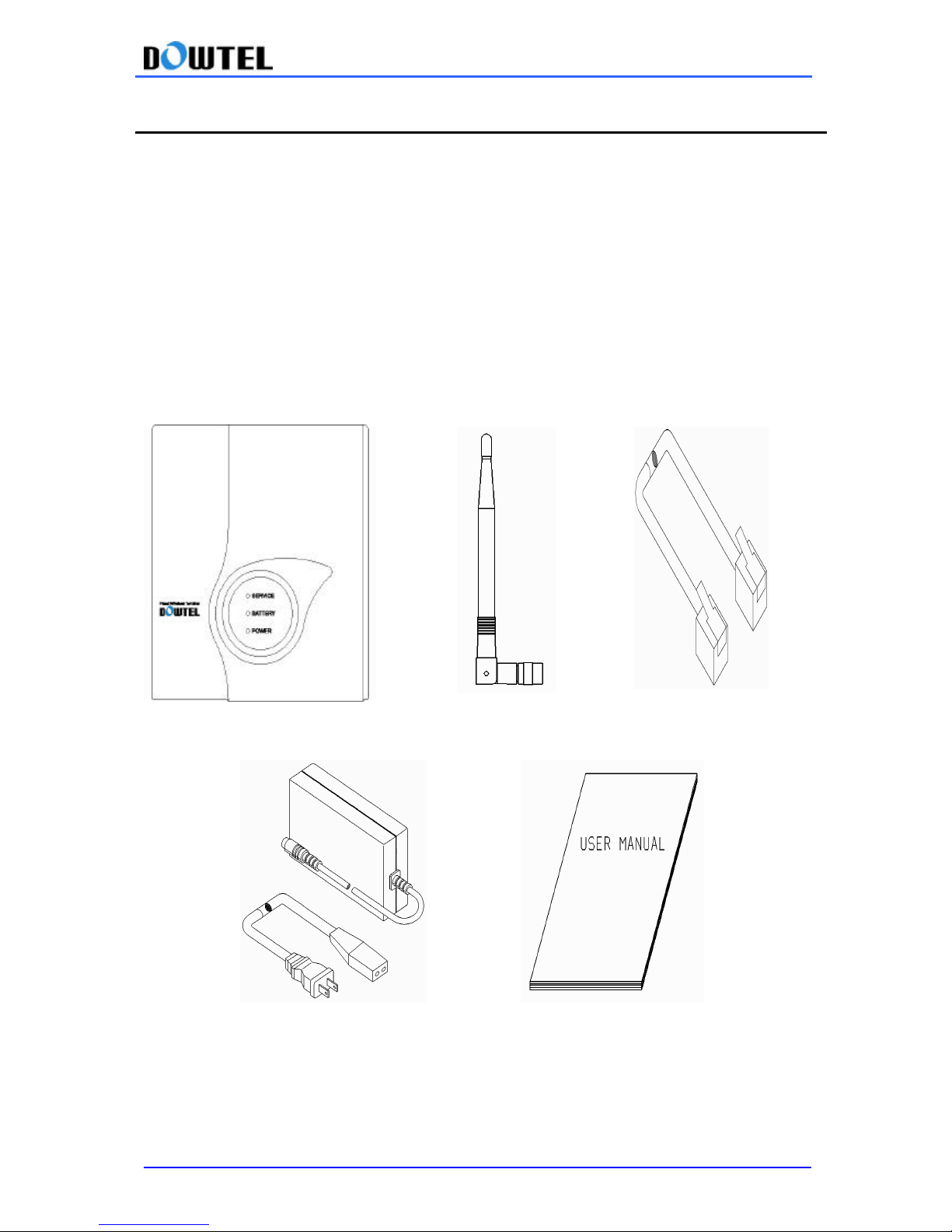
WS-2100/4100 terminal package contains the following parts and accessories. Upon open ing the
package please check and make sure if all of the parts and accessories are included. If there are
items missing, please contact the store where the unit was purchased.
-
-
FWT terminal Antenna TEL LINE
SMPS Manual
1.2 Name and Function of Each Part
Page 6
WS-2100/4100 Operating Manual
6
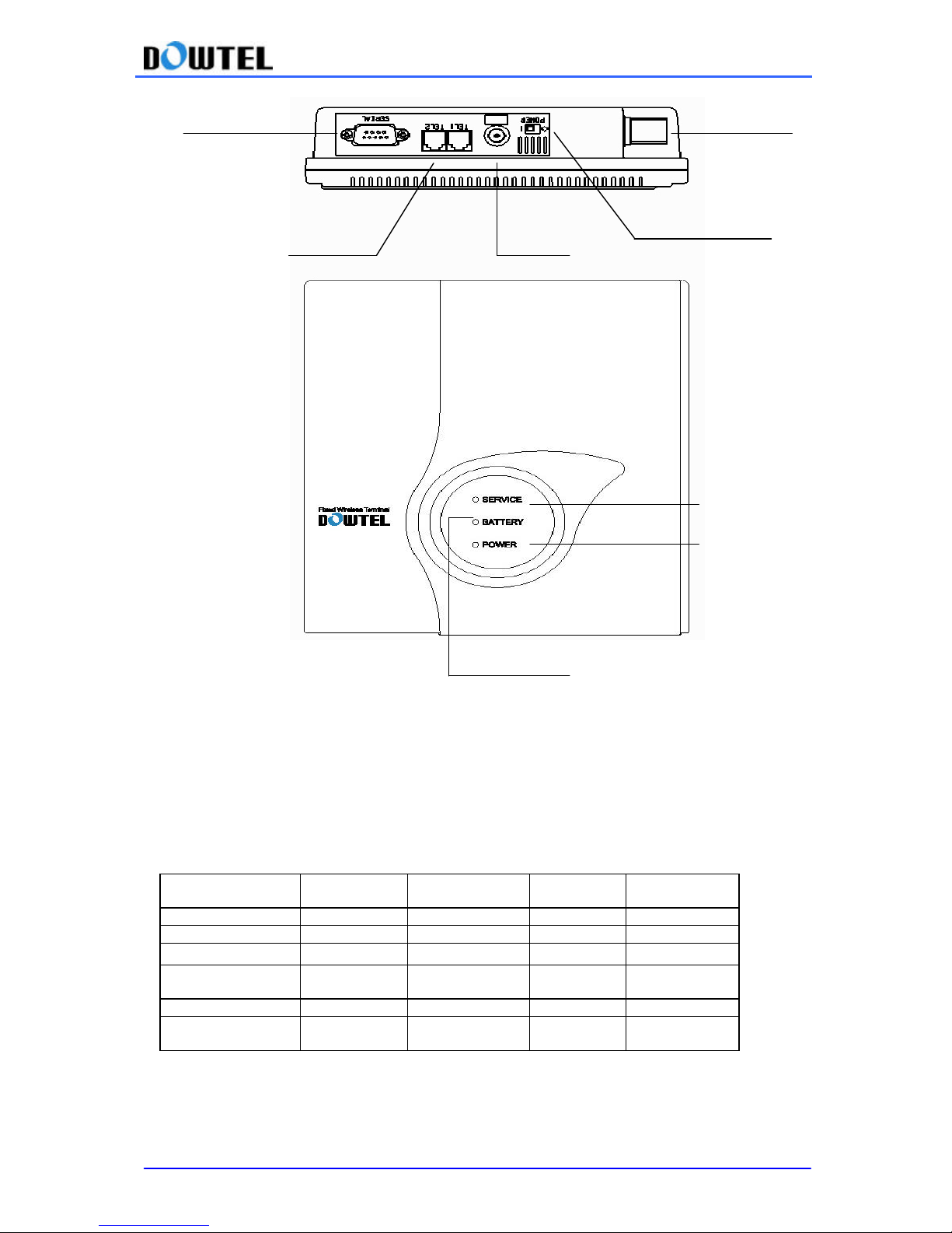
l POWER LED
LED lights in red indicates the external power is supplied.
l BATTERY LED
Indicates the status of backup battery.
The terminal can be operated if the backup battery is connected, even though the external power
supply is cut off.
Please refer to the following table for the LED operation.
- Once the battery LED starts to blink, a phone call is only possible for the next 2~3 minutes.
Battery Power (V) Battery Level
Battery LED Power LED
Terminal
Status
6.6 ~ 5 Green Off Normal
6.1 ~ 6.5 4 Green Off Normal
5.8 ~ 6.0 3 Orange Off Normal
5.6 ~ 5.7 2 Orange & Blink
Off
Normal
Warning Tone
~ 5.5 1 Off Off Power off
External power
supply
Off Red Normal
SERIAL PORT ANTENNA
RJ-11 JACK
DC JACK
POWER SWITCH
BATTERY LED
POWER LED
SERVICE LED
Page 7
WS-2100/4100 Operating Manual
7
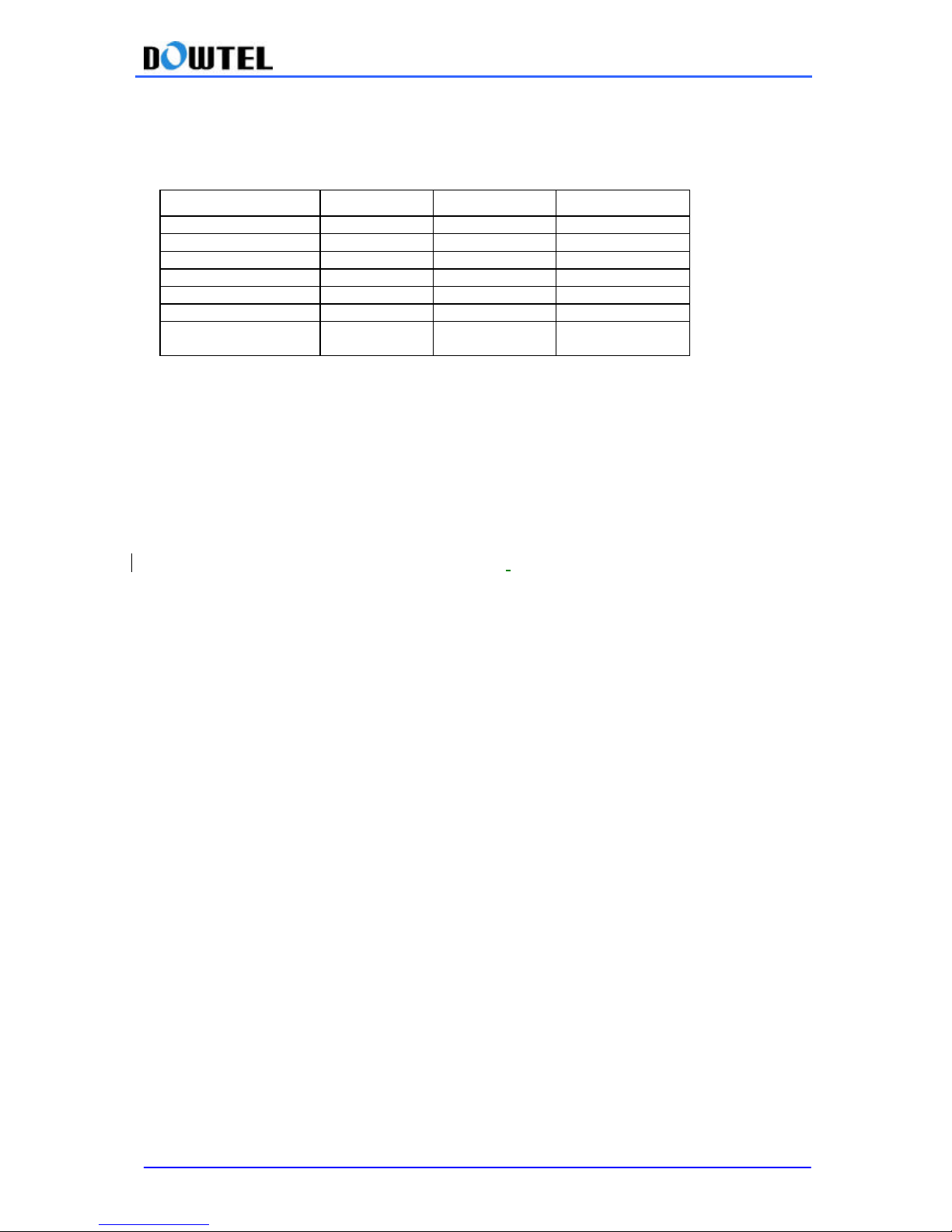
l SERVICE LED
Indicates the Signal Strength in your area. For better signal strength, please perform signal
strength test to find the best operating location.
Power intensity (dBm) RSSI Level LED status Terminal status
~ -85 5 Green Service available
-86 ~ -91 4 “ “
-92 ~ -97 3 “ “
-98 ~ -103 2 “ “
-104 ~ -110 1 Green & Blink “
-111 ~ 0 Red No Service
During a call Orange
Indicates during a
call
LED Green & Blink: Indicates minimum call service is available due to weak signal strength.
LED Green: Indicates the strong signal strength and the normal call service are available.
LED Red: Indicates call service is not available as the signal strength is too weak.
LED Orange: Indicates the call is in progress, regardless of the signal strength.
[Notice] Malfunction Indicator
In case of the terminal malfunction, Service LED and Battery LED will light up red and blink .
Please contact your service provider for service.
l DC JACK
The SMPS supplies the power to the FWT terminal.
- AC Input voltage of SMPS ranges from 100V to 240V.
l POWER SWITCH
The terminal has two power sources; External AC Power, and Internal DC Battery Power.
Even the AC power is disconnected to the phone by power failure, or for any reason, the power
sources will be automatically changed to the internal battery.
To disconnect all power from the phone, the power switch should be in OFF position.
l SERIAL PORT
The Serial Port used to connect the terminal to the PC for maintenance/repair, and data
communication.
l RJ-11 JACK
Connects to a land line phone or a fax.
- This terminal has 2 jacks.
- You can connect 2 phones at the same time but there is no mutual security function.
- You can connect up to 5 phones to the terminal using RJ-11 jack.
(A user must buy additional parts to extend the connection)
Page 8

WS-2100/4100 Operating Manual
8
1.3 Sound & Tone
1.3.1 Power-Up Sound
When the terminal’s power is turned on, a beep-sound is transmitted.
1.3.2 Dial Tone
Indicates that call service is available.
1.3.3 Warning Tone
The sound transmitted to the handset in the following cases.
- In case the call is not available due to broken air link.
- In case the dialing is delayed after the handset is picked up.
- In case the terminal is not in the correct working mode.
1.3.4 Howler Tone
In case the handset is not properly place d, loud alarm buzzer will sound for 30 seconds, after short
Warning Tone.
1.3.5 Keypad Tone
When the keypad is pressed, a tone will be transmitted through the handset.
1.3.6 Ring Sound
The sound transmitted to the buzzer indicating the receipt of a call while the handset is lifted
1.3.7 Low Battery Warning Tone
When the terminal operates with the built -in battery and the battery strength is weak, a Low Battery
Warning tome will be heard.
1.3.8 VMS Notification Tone
A VMS notification buzzer will sound when VMS Message has been received.
1.3.9 Error Tone
An Error Beep Tone will sound when the keypad is pressed incorrectly. In this case, the terminal
will ignore incorrect operation.
Page 9

WS-2100/4100 Operating Manual
9
1.4 Safety Instructions
l Basic safety precautions should always be followed to reduce the risk while using this
unit.
The WS -2100/4100 can be in service and remain in good condition for a long period of time if used
properly, and given proper care.
1) To reduce the risk of electric shock, do not disassemble or alter the terminal.
(Please contact the authorized service center for service or assistance)
2) Do not hold or make contact the antenna during a call.
3) Do not overload the wall outlets and extension cord.
4) Do not use this product near the water and never spill any liquid on the unit. This may result
in the risk of fire or electric shock.
5) Do not place this product on an unstable location (cart, stand or table). If this product
should fall from an unstable location, the result may be risk of serious damage.
6) Do not cover the slots and openings on the unit. They are provided for ventilation and
protection against overheating. Do not place this product near the heater or radiator where
proper ventilation is not provided.
7) This product should only be operated from the type of power source marked on the product.
If you are not sure of the type of power available, consult your dealer or local power
company.
8) Never push objects of any kind into this product, since this may result in a serious voltage
short and may result in the risk of fire or electric shock.
9) During thunderstorms, avoid using this product. There may be a remote risk of an electric
shock from lighting.
10) Unplug this product from the wall outlets and obtain service from an authorized service
center under the following conditions:
- When the power supply plug is damaged or frayed.
- If liquid has been spilled into this product.
- If this product has been exposed to water or rain.
- If this product does not work properly when the operating instructions are followed.
- If this product has been dropped or damaged.
- If this product exhibits a distinct change in performance.
Page 10
WS-2100/4100 Operating Manual
10
2. Installations
2.1 General Installation
l Thank you for choosing this product. Before installing the terminal, please check whether the
products package contains all the l parts and accessories are in the package. If there are items
missing, please contact the store where the unit was purchased. If you have all the necessary
parts and accessories, please follow the instructions shown below:
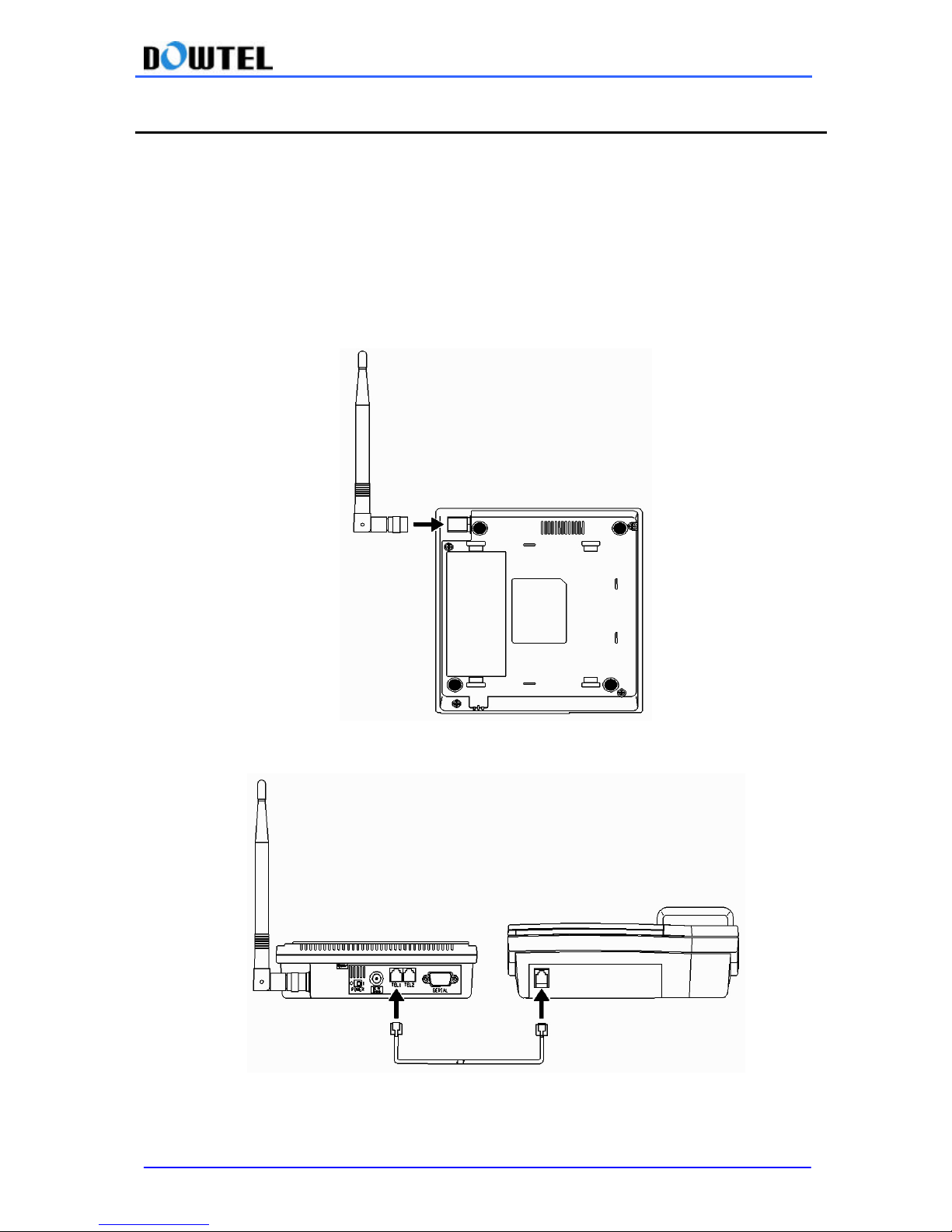
1) As shown in the figure below, plug in the antenna in the direction of the arrow and turn it
clockwise to connect with terminal.
2) Connect a regular phone set to the terminal using RJ-11 Jack as shown in the figure below.
There are 2 RJ -11 Jacks in the terminal and you can connect it to either one.
Page 11
WS-2100/4100 Operating Manual
11
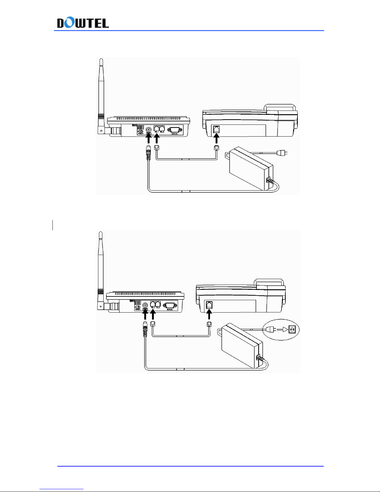
3) Connect the DC-JACK to the back panel of the terminal and insert the power jack to SMPS as
shown below.
4) Connect the power plug of SMPS to a power outlet.
5) Turn power on by moving the switch to the right.
l All 3 lamps (LED) light up initially.
l After a power-up melody plays through, a service lamp will turn green indicating call services is
available.
l At this time Red Power light and Green Service light will remain on.
Page 12

WS-2100/4100 Operating Manual
12
[Notes] Malfunction Indicator
In case of a malfunction, a service LED and a battery LED will light up in red and blink.
In this case, please contact your service provider.
Page 13
WS-2100/4100 Operating Manual
13
2.2 Installation For the Data Service.
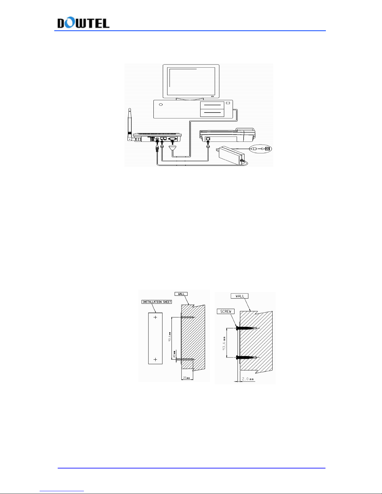
1) PC – FWT connection
< Connection of terminal to a PC for the Data communication >
As shown above, connect a RS-232 cable to the Serial Port of the terminal and COM1 (or COM2)
of PC. RS 232 cable is available from the service provider , or at any electronics store.
2.3 Installing the Wall Bracket (Option)
Before finalizing the precise location of the phone, please perform the signal strength test to
ensure the best operating condition location for the assembled unit.
① For installing the unit into a concrete wall, attach the installation sheet onto a concrete wall
and make 3mm holes with a drill at the marked location. When installing mounting screws,
do not screw them in all the way. Leave 2mm space between the screw head and the
installation sheet.
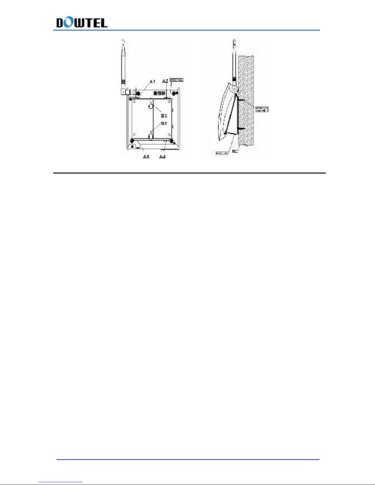
② Assemble the Wall-Bracket by using A1~A4 (4 Places) slots on the bottom of the phone, and
then hook up B1 ~ B2 holes of the Wall-Bracket to the screw head.
Page 14
WS-2100/4100 Operating Manual
14
3. Basic Functions
3.1 Power On
The power for the terminal is supplied through SMPS and built-in battery.
When the power is supplied through SMPS, the battery is automatically being re-charged and in
case of a power loss, the power source is automatically changed from AC power to interna l Battery.
In addition, when the external power is restored, the power source is automatically back to AC
power
3.1.1 How to Operate with External Power.
Connect the SMPS to the DC- JACK in the terminal and then the power plug of SMPS to a power
outlet.
I nsert the power jack properly, and then turn the power on by moving the power switch to right to
position [I ].
If the power is supplied to the terminal, 3 lamps will come on initially, and the Service Lamp and
Power Lamp will stay illuminated, when call service is available.
3.1.2 How to Operate with the Built-in Battery.
If the SMPS gets unplugged or if there is a power failure while the power switch is on, power is
automatically switched to the battery built into the terminal. The battery must be always charged
up to the full operational strength and if the external power is restored, the power source will be
automatically switched back to AC power, and the battery will be re-charged up to full strength
automatically.
3.2 Power Off
If the power switch is moved to left to the position [O], both the external and internal powers will be
disconnected.
3.3 Making a Call
Page 15

WS-2100/4100 Operating Manual
15
3.3.1 General Method
1) Pick up the handset and you will hear a dial tone (off-hook state).
2) If you hear the Dial Tone, then you can ma ke a call.
* If there is a warning tone at a 0.5 second interval , you can not make a call, check the LEDs,
and contact your service provider.
3) Dial the telephone number and press the “*” button.
4) Start talking with the other party when the call is connected (Service LED is orange).
5) If you put down the handset (on-hook), the call will be terminated.
[Notice] Malfunction Indicator
In case of a malfunction, both a service LED and a battery LED light up in red and blink at the
same time.
Please contact your service provider for assistance.
3.3.2 Making a Call Using the Speed Dial Function
In order to use this function, the Speed Dial Function must be set up in advance.
To set up Speed Dial Function, please refer to section 4.1.
1) For single digit addresses (1-9) in your Phonebook, pick up the handset and press the
desired number and press the “*” button, or press the desired number and hold it down until
you hear the ringing. When the call is connected, the Service LED will be changed to
Orange, and you can start to talk. To end the call, just hang up the handset.
2) For double digits numbers (10-99) in your Phonebook, pick up the handset, and press the
desired numbers and press the “*” button, or press the first digit shortly and press second
digit and hold it down until you hear the ringing. When the call is connected, the Service
LED will be changed to Orange, and you can start to talk. To end the call, hang up the
handset.
3.3.3 Making a Call Using the Redial Function
The Redial Function is used when you want to make a call to the number last dialed.
1) Pick up the handset and press the “*” button and hold it down, a call is connected to the last
number dialed. But, if no number was dialed after power was on, this function will not work.
2) Start talking when the Service LED turns orange indicating the call has been connected to
the other party.
3) The call is terminated when you hang up the handset.
Page 16

WS-2100/4100 Operating Manual
16
3.4 Receiving an Incoming Call
3.4.1 On-Hook State
1) The phone will ring when receiving an incoming call.
2) Pick up the handset, and start talking when connected to the other party (Service LED is
Orange).
3) A call is terminated when you hang up the handset.
3.4.2 Off-Hook State
1) Even if the handset is off-hook state with dial tone or warning tone, you still can receive an
incoming call. When there is an incoming call at Off-Hook state, the telephone will ring
through the buzzer . At this time, press the hook-flash and answer the phone. But, receiving
a call in Off-Hook state is possible only when there is either Dial Tone or the Warning Tone.
It rings through the buzzer.
2) Talk when the other party is connected. (Service LED is Orange).
3) To end the call, hang up the handset.
Page 17

WS-2100/4100 Operating Manual
17
3.5 How to Use Analog G3 Fax
Terminals with the Analog G3 Fax Board can send and receive documents with Fax machine. Fax
Board is an optional item. To use Fax function, Fax machine should be connected with terminal.
3.5 .1 To Send a Document by Fax
Pick up the Fax handset and make sure there is a dial tone then press *00 and then dial the
number you want to send the Fax on Fax machine and follow the instructions of the Fax machine
connected to the terminal.
3.5 .2 To Receive a Document by Fax
You need to set the Terminal to Receiving Mode to receive documents through the Analog G3 fax
using this terminal. Pick up the Fax handset and press ###005 to set the terminal to Receiving
Mode of Analog G3 fax. An incoming Fax message will be received by Fax machine connected to
the terminal.
[Note] Once the terminal is set to the Analog G3 Fax Receiving Mode, you can not receive
regular incoming calls. To go back to normal mode after receiving Fax, press ###000 to release
Fax Receiving Mode.
3.6 Data Service
Using RS-232 Data Cable, you can connect this terminal to PC for Internet, PC Communication
and/or PC Fax communication, if your service provider provides Wireless Data Communication
Service.
3.6.1 Setting Data Service Receiving Mode
There are several options for Data Service Receiving Mode as follows;
• PC Modem Receiving, One Time Mode; After one connection and/or after 10 minutes, the
setting will be automatically released and terminal will be changed to Normal Phone mode.
• PC Modem Receiving, Always Mode: The terminal will remain at this mode until you
changed the mode or the power is turned off.
• PC Fax Receiving, One Timer Mode; After one connection and/or after 10 minutes, the
setting will be automatically released and the terminal will be changed to Normal Phone
mode.
• PC Fax Receiving, Always Mode; The terminal will remain at this mode until you change the
mode or the power is turned off.
[Note]
While terminal is at Data Service Receiving mode, you can not make or receive calls, so after
using Data Receiving service, you have to change the mode to Normal Phone mode, by pressing
###000.
Page 18

WS-2100/4100 Operating Manual
18
1) Setting Data Services Receiving Mode using a regular phone set.
You can set the unit to the Data Service Receiving Mode by using a regular phone set connected
to the terminal.
① Pick up the phone handset and press ###001.
The unit has been programmed to the PC Fax Receive, One Time M ode.
② Pick up the phone handset and press ###002.
The unit has been programmed to operate in the PC Fax Receive Always Mode.
③ Pick up the phone handset and press ###003.
The unit has been programmed to the P.C MODEM Receive, One Time Mode.
④ Pick up the phone handset and press ###004.
The unit has been programmed to the P.C MODEM Receive, Always Mode.
⑤ The default setting value for Normal Phone Mode is ###000 and after using Data Service,
please change the mode to Normal Phone Mode.
2) How to set Data Service Receiving Mode using AT Command.
By using a communication emulator of a PC connected to the terminal, you can set the Data
Service-Receiving mode.
First, Run the communication emulator program in the PC and input each command as described
below.
① To remove the Data Service Receiving M ode of terminal, type ‘AT+RCVMOD=0’ in the program
and press the ENTER KEY. When the setting is set, the unit will indicate OK and operates in the
normal phone mode.
② To set the terminal to the PC Fax Receiving, One Time Mode, type ‘ AT + RCVMOD = 1’ in the
program and press the ENTER KEY. It will indicate OK when the setting has been set.
③ To set the terminal to PC Fax Receiving Mode (always), type ‘AT + RCVMOD=2 ’ in the program
and press the ENTER KEY. The unit will indicate OK when the setting has been set.
④ To set the terminal to the Modem Receiving Mode (one time), type ‘ AT + RCVMOD = 3’ in the
program and press the ENTER KEY. It will indicate OK when the setting is completed.
⑤ To set the terminal to the Modem Receiving M ode (always), type ‘AT+RCVMOD =4’ in the
program and press the ENTER KEY. The unit will indicate OK when the setting has been set.
⑥ The default setting in the terminal booting is ‘ AT+RCVMOD = 0’ and this is for normal phone
mode.
Remark !!!
Check if the system supports 2-Number or 2-Stage Dialing. If system supports this function, our
FWT supports automatic “Data Service and Analog G3 Fax receiving” without setting up the
receiving mode <3.5 How to use Analog G3 Fax and 3.6 Data Service> To use the function of 2Number or 2-Stage Dialing, you are requested to contact Service Provider since you should get the
separate Prefix which is designated by Service Operator.
Page 19

4. Supplementary Functions
4.1 Call Functions
4.1.1 Speed Dial
This terminal will store up to 99 phone numbers using 2 digit addresses (01-99). The stored
number in the Phonebook allows a call to be placed by pressing the two digit address. This
terminal has the ability to search and edit numbers stored in the Phonebook, and the methods for
storing, searching and editing a stored phone number are explained in section 4.2.
4.1.1.1 Speed Dial Function On / Off
You can set the Speed Dial function by entering the following functions.
1) Speed Dial On
Press;
#0*100 à 1 à 1 à 1 à * : Speed Dial function on
2) Speed Dial Off
Press;
#0*100 à 1 à 1 à 2 à * : Speed Dial function off
4.1.1.2 Making a Call Using the Speed Dialing Function
1) Make sure the Speed Dial Function is “on” and find the memory station number in the
Phonebook.
2) If the saved address is a single digit, between 1 and 9, pick up the handset and press the
number and hold it down, or press the number briefly and press the “*” button, then the call will be
made.
3) If the saved address is two digits, pick up the handset and press the first digit and then press the
second digit and hold it down or press both digit briefly and press the “*” button, then a call is made.
[Notice] If you attempt a Speed Dialing while the Speed Dial Function is OFF, an error tone will
sound to indicate wrong operation.
Page 20
WS-2100/4100 Operating Manual
20
4.1.2 Hot Line function
1) This function is used to make an automatic, quick call to a designated number without
dialing. Just pick up the handset, then a call will be made.
2) The Hot Line number should be registered at address 99 in the Phone book. Hotline
operates in 2 modes;
*Timed Hot Line; The call will be made in delayed manner between 4-8 seconds (sending
waiting time), depending on your default value, after you pick up the handset. Original
default value is 6 seconds.
*Immediate Hot Line; The call will be made as soon as you pick up the handset.
- The Hotline function overrides any other functions.
4.1.2.1. Hot Line function On / Off
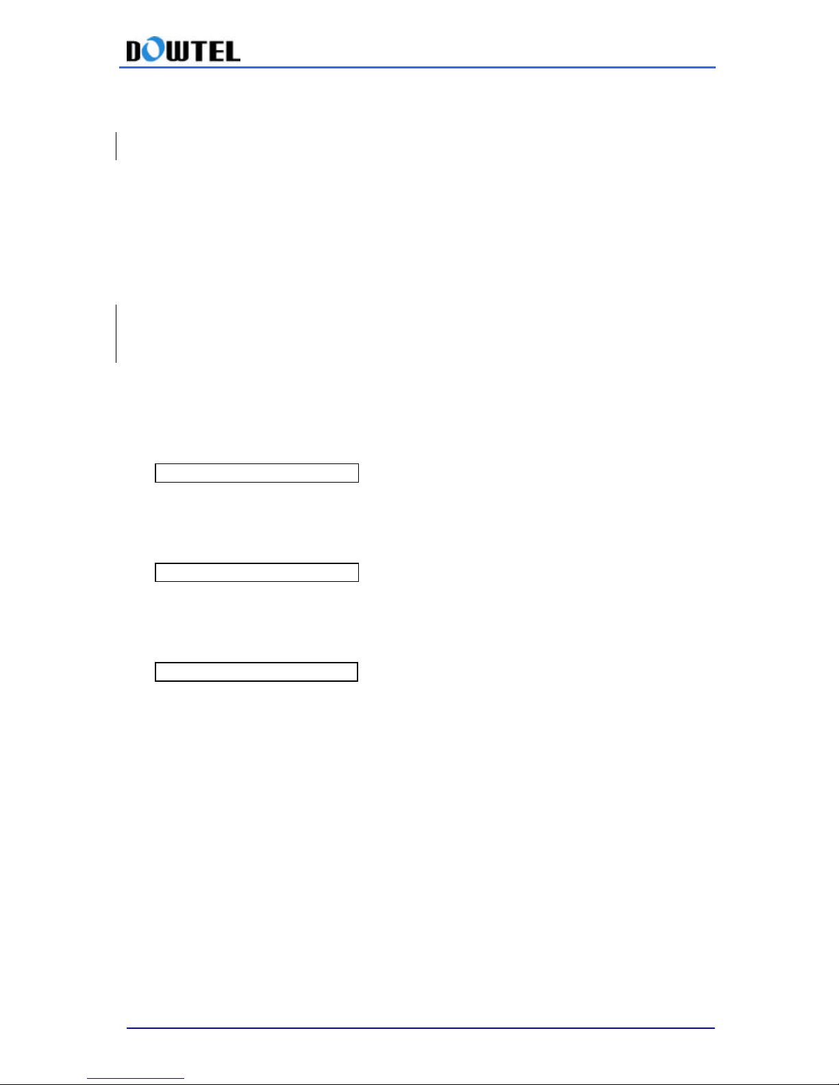
1) Timed Hot Line On
Press;
#0*100 à 1 à 2 à 1 → *
2) Immediate Hot Line On
Press;
#0*100 à 1 à 2 à 2 → *
3) Hot Line Off
Press;
#0*100 à 1 à 2 à 3 → *
4.1.2.2 Making a Hot Line Call
When a phone number is saved in address [99], and the Hot Line function is set to the Timed Hot
Line mode, a call is automatically made, and if the send waiting time (4 ~ 8 seconds) elapses, if the
handset is lifted. .
If the Hot Line function is set to the Immediate Hot Line mode, and you pick up the handset, the
call is made automatically to the number saved in the memory address [99].
[Note]
If the Hot Line function is in the Immediate Hot Line mode, a call may not be made to another
number . In this case, to make a call to another number, change the setup mode. Pick up the
handset and press <#> within 1 second and go to the setup mode, and deactivate the Hot Line
function as shown at 4.1.2.1.
Page 21
WS-2100/4100 Operating Manual
21
4.2 Phone Book
4.2.1 Storing Phone Numbers
Press;
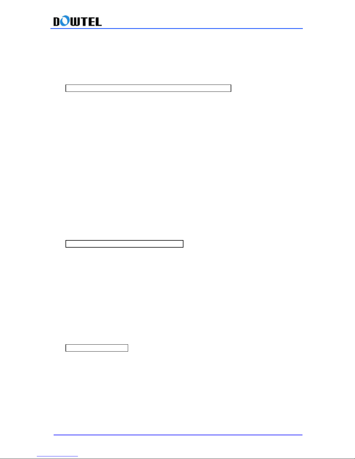
#0*100 à 2 à 1 à address (2 digits) à phone number à *
① Pick up the telephone handset and enter the code as shown below.
< #0*100 à 2 à 1 >
enter the 2 digit address you would like to store the phone number. Suppose the address is <4>,
press [04]
② Enter the phone numbers to be saved digit by digit .
③ When you press <*> button (saving), you will hear a <confirmation beep> indicating the number
has been successfully stored.
4.2.2 Deleting Phone Numbers
4.2.2.1 Deleting a Number
#0*100 à 2 à 2 à address (2 digits) à *
① Pick up the telephone handset and enter the code as shown below.
< #0*100 à 2 → 2 >
② Enter the 2 digit address to be deleted.
③ When you press <*> button (saving), you will hear a <confirmation beep> indicating the
number has been successfully deleted .
4.2.2.2 Deleting All Numbers
#0*100 à 2 à 3 à *
① Pick up the telephone handset and enter the code as shown below.
< #0*100 à 2 → 3 >
② When you press <*> button (saving), you will hear a<confirmation sound> indicating all stored
numbers have been successfully deleted.
Page 22
WS-2100/4100 Operating Manual
22
4.3 Additional Functions
4.3.1 Alarm Reminder
The terminal sends a reminder to the user by ringing at a specified time. The time is set using a
24 hours format. 2 specific settings are possible.
The <one time mode> activates the alarm only once while the <always mode> it activates the
alarm everyday at the same specified time.
The time and function setting are shown below.
◆ Setting the Alarm Time
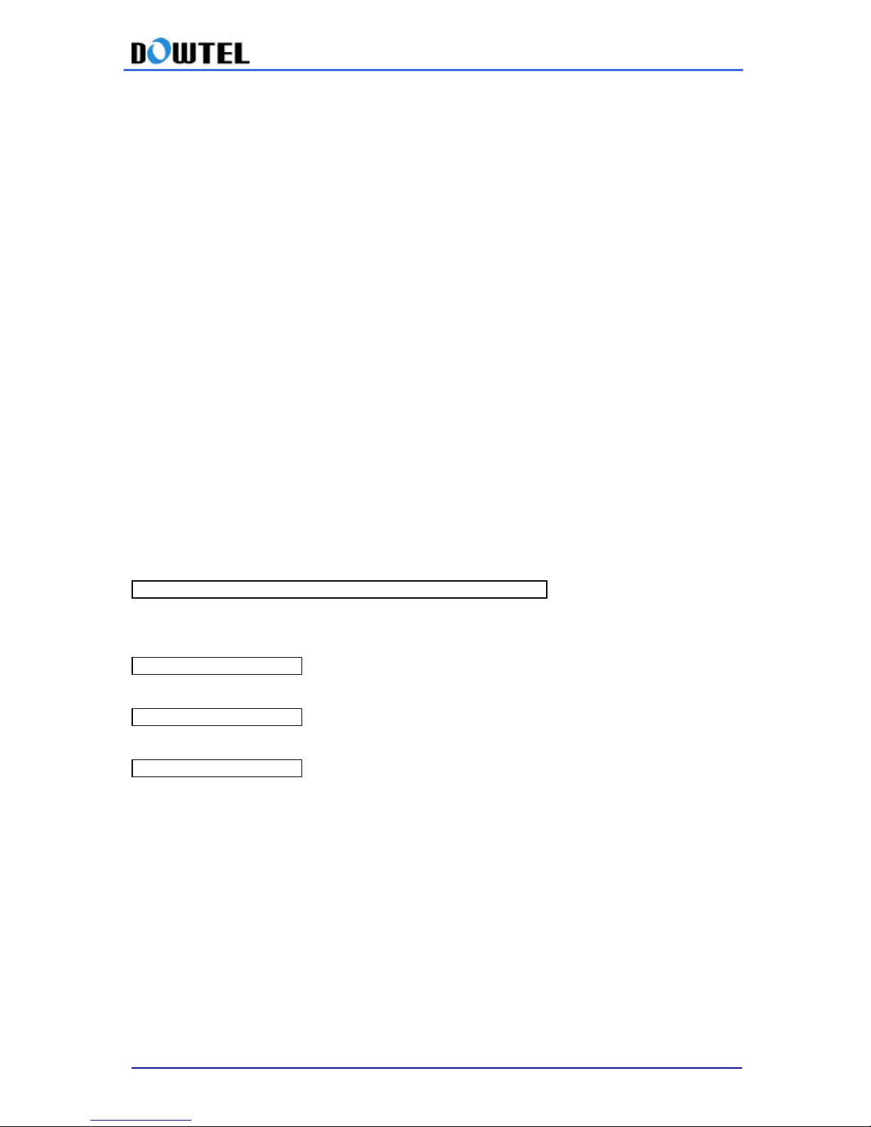
① Enter #0*100 à 3 à 1 à 1
② Input four digits (using a 24 hours clock format) for the desired time and then press <*> button.
Example: 3:30 pm, press < 1 à 5 à 3 à 0 à * > sequentially.
③ After setting the alarm time, the Detailed Alarm Setting function is automatically set to the <one
time mode> and when the specified time comes, the alarm is activated.
④ After setting the alarm time, if you want to have the alarm activated at the same time every day,
enter #0*100 à 3 à1à 3 à * to change the Detailed Alarm Setting function to <always mode>.
⑤ In case you want to reset the alarm function enter #0*100 à 3à1à 4 à * .
#0*100 à 3 à 1 à 1 à hour (4 digits, 24 hours format) à *
: Alarm time input and setting (one time)
#0*100 à 3 à 1 à 2 à * : Alarm Reminder on (one time)
#0*100 à 3 à 1 à 3 à * : Alarm Reminder on (Always)
#0*100 à 3 à 1 à 4 à * : Alarm Reminder off
Page 23
WS-2100/4100 Operating Manual
23
4.3.2 Handset Volume Control
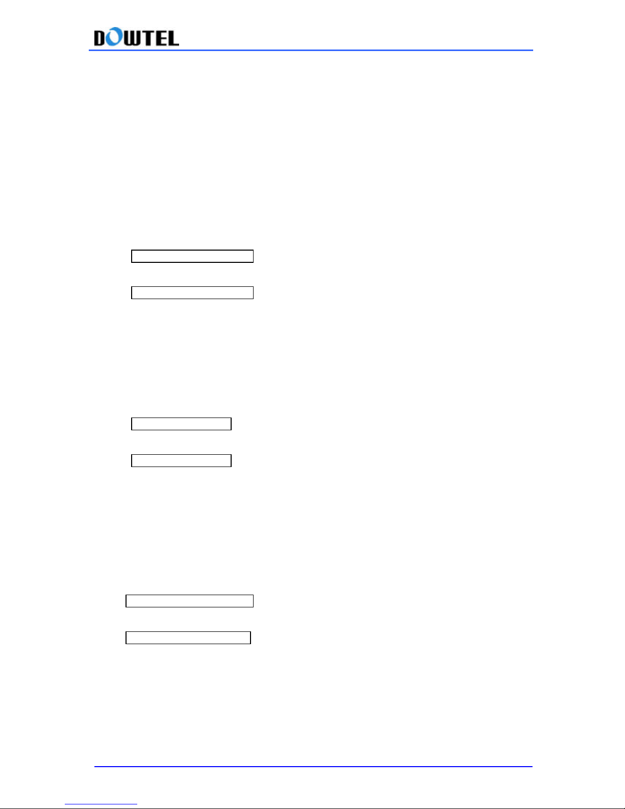
This function is used to control the volume of handset. The handset volume can be set at 5
different levels and the default setting is Level 3.
2 methods for changing this setting are listed below.
1) Change using the menu code (Idle State)
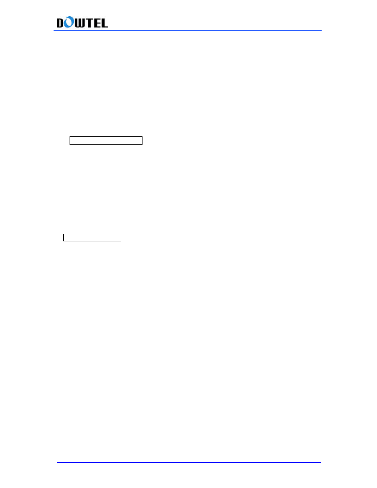
① Enter #0*100à3à2
② Select and press a desired level: #1 (Level 1: minimum) , #2(Level 2) , … , #5 (Level 5:
maximum).
③ Press <*> button to save the setting.
#0*100 à3à2à1~5à * : Handset Volume Control (method 1)
2) Fast operation (Call State)
① Pick up the telephone handset.
② Press <###30>
③ Enter a number between <1> ~ <5>.
④ Press <*> button to save the setting. When the setting is successfully set, you will hear a dial
tone.
###30 à 1~5 à * : Handset Volume Control (method 2)
Page 24
WS-2100/4100 Operating Manual
24
4.3.3 Setting the Voice Privacy Function
This terminal is equipped with voice privacy function to prevent illegal tapping.
There are two detailed settings available, <Standard> for regular level voice privacy mode and
<Enhanced> for reinforced voice privacy mode.
The Voice Privacy function can be enabled using the method shown below.
1) While In idle state
① Enter #0*100à3à3 sequentially.
② Press <1> button for < Enhanced > mode and <2> button for < Standard > mode.
③ Press <*> button to save the setting .
#0*100 à 1 à 3 à 1 à * : Enhanced Voice Privacy On
#0*100 à 1 à 3 à 2 à * : Standard Voice Privacy On
2) During a call
①Enter #0*100à1 sequentially.
②Press <1> button for <Voice Privacy On> and <2> button for <Voice Privacy Off>.
③Press <*> button to save the setting.
#0*100 à 1 à 1 à * : Enhanced Voice Privacy On
#0*100 à 1 à 2 à * : Standard Voice Privacy Off
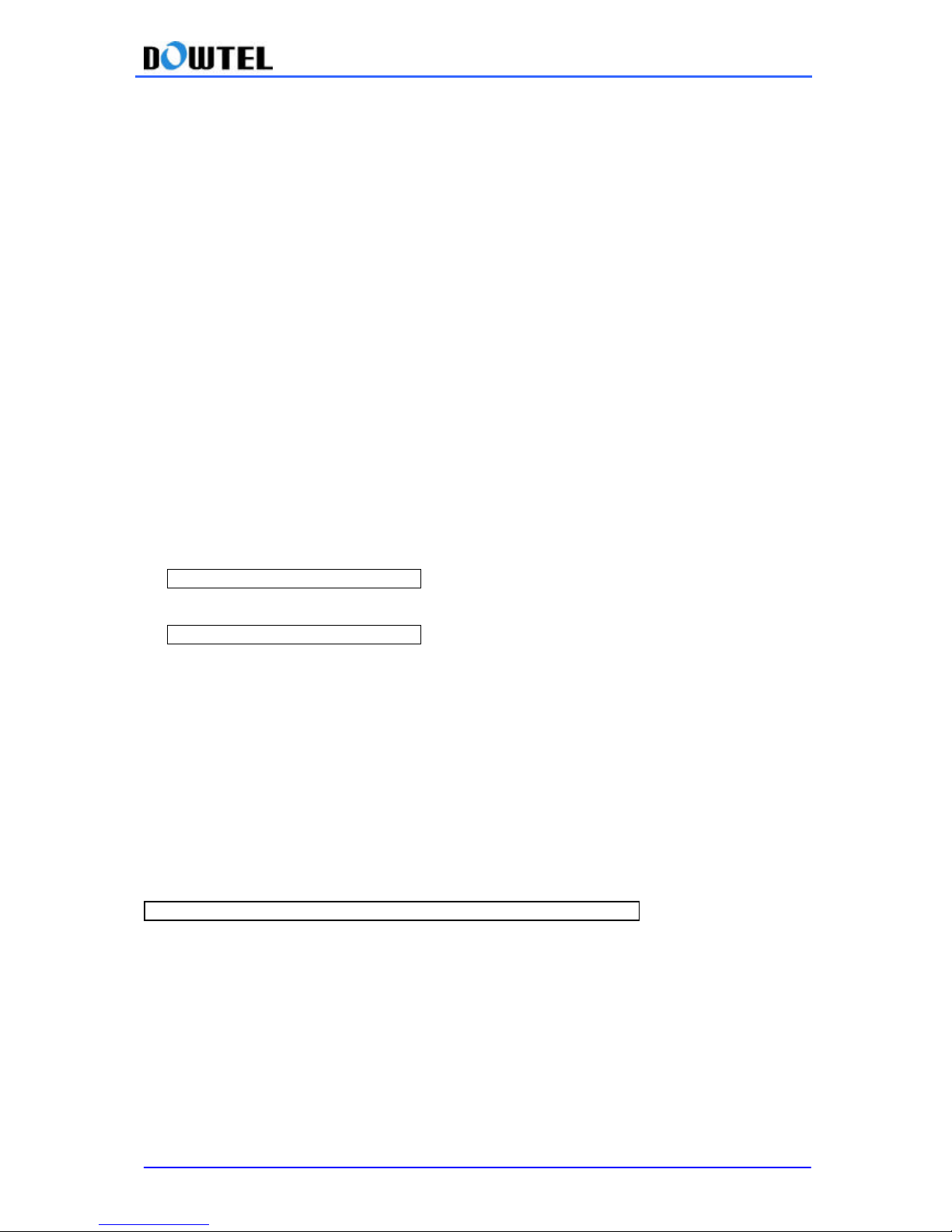
4.3.4 Serial Baud Rate Setting
This terminal supports the Data Service function with a connection to PC through a RS-232 Serial
Interface. T wo communication speeds are used.
115,200 bps for the high-speed packet data service and 19,200 bps for a modem, PC fax and low
speed packet data service.
1) Setting the Serial Baud Rate to 19,200 bps
#0*100à3 à3à1 à *
2) Setting the Serial Baud Rate to 115,200 bps
#0*100à3à3à2 à *
Ref.] The default value is 115,200bps. If the terminal power turns off and on while other
Baud Rate was selected, the Baud Rate of the terminal will automatically return to the
default value of 115,200bps. In this case, the prefered Baud Rate setting is needed again.
4.4 LOCK
Page 25
WS-2100/4100 Operating Manual
25
4.4.1 Outgoing Lock
The Outgoing Lock function is used to block other people from using the terminal.
If you make a call while this function is on, the terminal generates an error sound indicates that
making a call is not possible. This function only prevents outgoing calls. Receiving a call is still
possible while the Outgoing Lock function is turned on.
To use the phone, you need to unlock the phone by entering your password.
The Default setting is <Outgoing Lock off>.
4.4.1.1 Turning the Outgoing Lock On / Off
① Enter #0*100 à 4
② Enter your four digit password.
[Note] If you enter an incorrect password, the Reject Tone will sound and you need to re-enter the
password.
③ Press <1> button to enable this function and <2> to reset this function.
④ Press <*> button to terminate this function.
#0*100 à 4 à password à 1 à * : Lock function On
#0*100 à 4 à password à 2 à * : Lock function Off
4.4.2 Changing Lock Code (User’s Password)
① Enter #0*100 à 4 to change your password.
② Press <3> after entering a password in use.
③ Enter the new password and press * button.
④ Enter the new password again and press * button.. The new password has been activated.
#0*100à4àpasswordà 3 ànew passwordà * ànew passwordà * : password change
[ Note ]
The Default password is 0000
4.4.3 Reset as Default
This function is used to change the main settings of the terminal back to the default settings, which
were programmed into the terminal at the factory.
Page 26
WS-2100/4100 Operating Manual
26
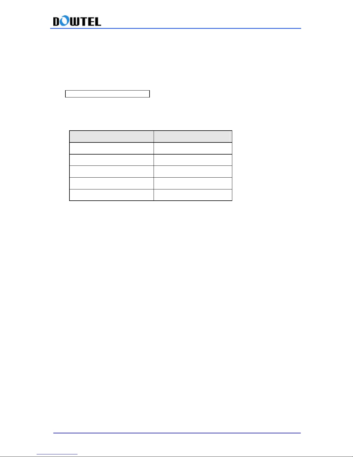
◆ How to reset to the default setting.
① Press #0*100 à4
② Enter your password and press <4>.
③ If you press <*> button, all the major functions listed below are reset to the following values.
#0*100 à4àpasswordà 4 à * : How to do the default setting
[Note]
Reset items and their status are as shown in the table below.
Items Status
Speed Dial Off
Hot line call Off
Alarm Off
Outgoing Lock Off
Handset Volume Level 3
Page 27
WS-2100/4100 Operating Manual
27
4.5 Maintenance Setup
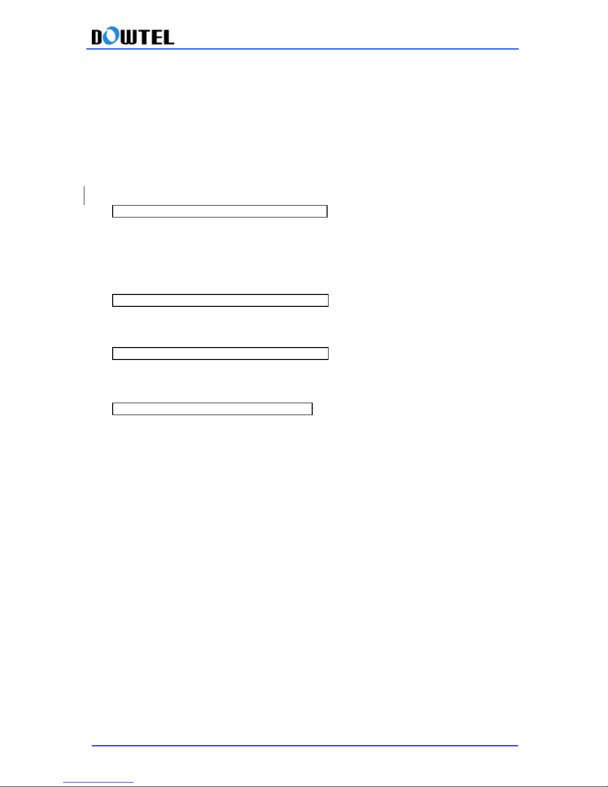
4.5.1 CLIP Setting
Since this terminal does not have an LCD, incoming calls are displayed on the LCD of the specific
module or telephone connected to the terminal.
Consequently , a communication method between the terminal and the module need to be set in
one of the following two available modes: DTMF mode and FSK mode.
① DTMF mode
#0*100à8àMaintenance Codeà1à1à * CLIP method setting (DTMF mode)
② FSK mode
[ Type 2 ]
- Type 2 FSK mode supports the Multi-Format type FSK.
#0*100à8àMaintenance Codeà1à2à1à * CLIP method setting (FSK Type2 mode)
[ Type 1 ]
- Type 1 FSK mode supports the Single-Format type FSK.
#0*100à8àMaintenance Codeà1à2à2à * CLIP method setting (FSK Type1 mode)
③ CLIP mode off
#0*100à8àMaintenance Codeà1à3à * CLIP method setting (CLIP mode off)
☞ Reference : Maintenance Code is “0202”
This code is used for maintenance & repair only.
Page 28

WS-2100/4100 Operating Manual
28
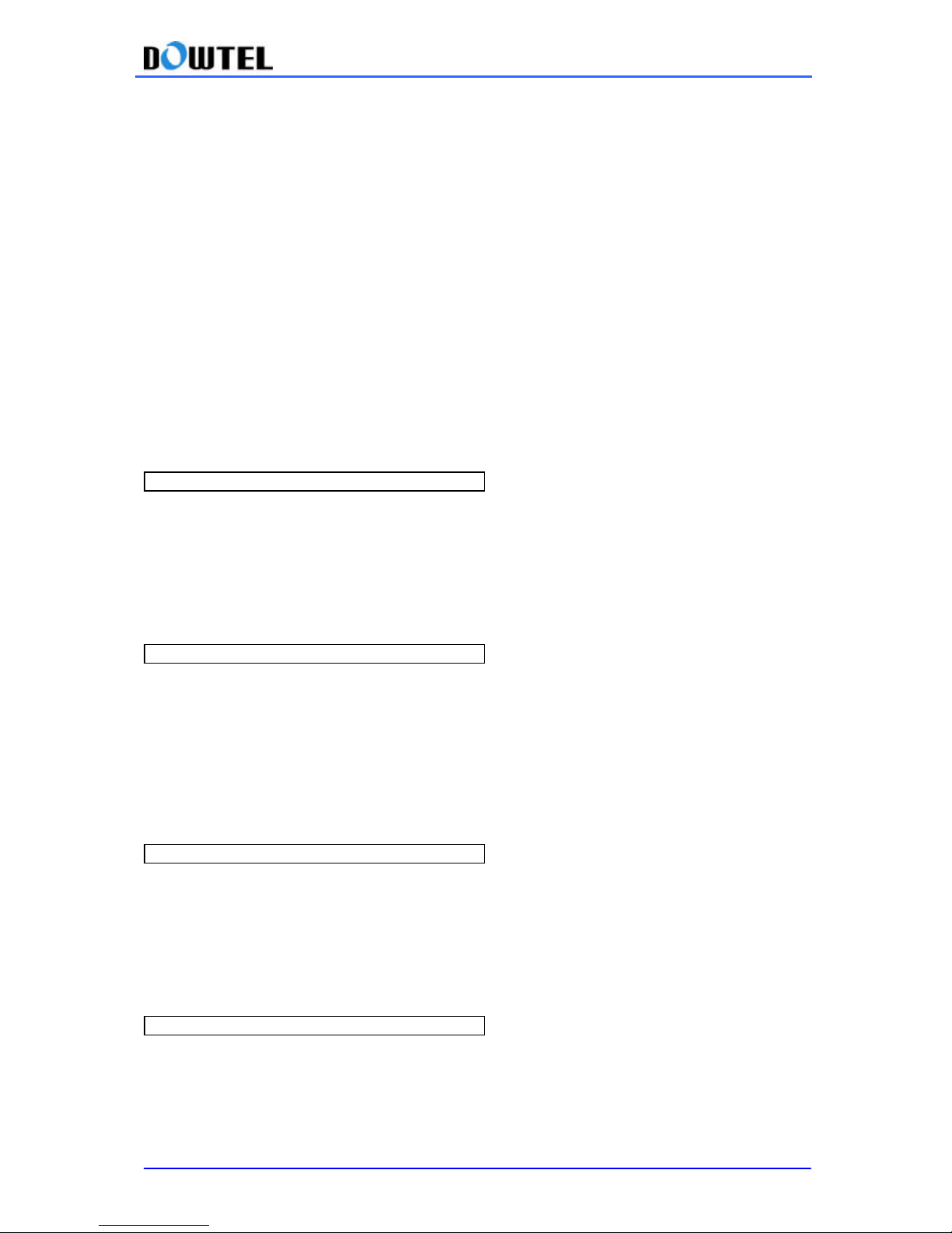
4.5.2 Analog G3 Fax Setting
1) WS-2100/4100 support Analog G3 Fax Service using the standards below:
- IS-99/IS-707.4 based PC Fax standard
- IS-707A.7 Analog G3 Fax standard
[Note]
In case of IS-99/IS-707.4 based PC Fax standard, a service provider will require the user to decide
the fax receiving method in advance: a PC fax program or Analog G3 fax.
(The fax program or the Analog G3 Fax becomes a Default Fax Receiver)
2) In case of IS -99/IS-707.4 based PC Fax standard,
① Enter #0*100à8àMaintenance Codeà2à1 sequentially
② Set the Default Fax Receiver
Press <1> button to receive an incoming fax through a PC fax program.
Or press <2> button to receive an incoming fax through the Analog G3 Fax machine connected to
the terminal.
③ Press <*> button to save the setting.
[Note]
The Default Fax Receiver function is system-dependent.
▶ When a Single Phone Number is used
: If a user use a single phone number for both fax and voice call, the Data Service Receiving M ode
Setting in section <3.6.1>will determine whether a voice call will be processed or a fax
transmission will be processed. In this case, Default Fax Receiver Setting does not have any
effect.
▶ When two Phone Numbers are used.
: In other words, if one number is dedicated to voice call and the other to fax despite using in the
same terminal, an incoming fax will be received automatically since fax service option is already
available. Accordingly, depending on what the Default Fax Receive se tting is, the terminal receives
a fax via a PC fax program or through an Analog G3 fax machine connected to the terminal.
3) In case of IS -707A.7 Analog G3 Fax standard
① Enter #0*100à8àMaintenance Codeà2 sequentially
② Press <2> button
③ Press <*> button to finish
Page 29
WS-2100/4100 Operating Manual
29
4.5.3 Default Data Rate setting
This terminal supports the standard data rates listed below.
- IS-99 Rate Set 1
- IS-99 Rate Set 2
- IS-707.4 Rate Set 1
- IS-707.4 Rate Set 2
The following is the Default Rate setting for Data Signal access.
1) Setting IS -99 Rate Set 1 (9.6K)
① Enter #0*100à8àMaintenance Codeà3 in order.
② Press < 1> button.
③ Press <*> button to save the setting.
#0*100à8àMaintenance Codeà3à1 à *
2) Setting IS -99 Rate Set 2 (14.4K)
① Enter #0*100à8àMaintenance Codeà3 in order
② Press <2> button
③ Press <*> button to save the setting
#0*100à8àMaintenance Codeà3à2 à *
3) Setting IS -707.4 Rate Set 1 (9.6K)
① Enter #0*100à8àMaintenance Codeà3 in order
② Press <3> button
③ Press <*> button to save the setting
#0*100à8àMaintenance Codeà3à3 à *
4) Setting IS -707.4 Rate Set 2 (14.4K)
① Enter #0*100à8àMaintenance Codeà3 in order
② Press <4> button
③ Press <*> to save the setting
#0*100à8àMaintenance Codeà3à4 à *
4.5.4 Ringer Frequency & Cadence Control
You can set the Ringer Frequency and On/Off T ime (Cadence) in this terminal.
Page 30

WS-2100/4100 Operating Manual
30
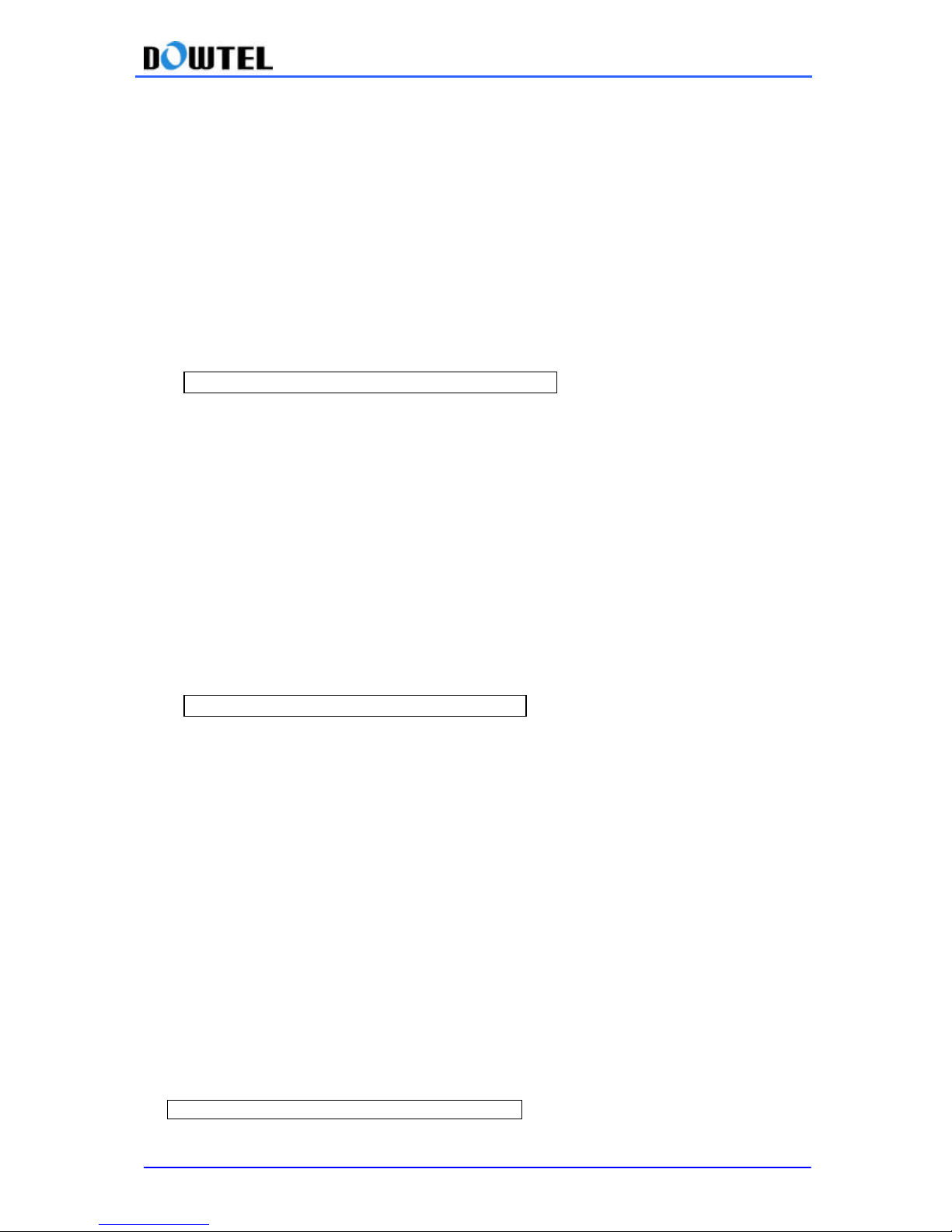
The Default setting is 20Hz, 1 Sec. On – 2 Sec. Off.
Listed below are the ringer frequency selection and Cadence settings.
① Enter #0*100à8àMaintenance Codeà4
② Select the ringer frequency
Press the desired number between No. 1(16Hz), No . 2(20Hz), No. 3(25Hz)
③ Select Cadence
No 1 (1 sec On – 2 sec Off),
No 2 (0.4 sec On – 0.2 sec Off - 0.4 sec On – 2 sec Off),
No 3 (1 sec On – 4.5 sec Off),
No 4 (1 sec On – 4 sec Off),
No 5 (0.25 sec On – 0.25 sec Off - 0.25 sec On – 1.25 sec Off),
No 6 (2 sec On – 4 sec Off)
④ Press <*> button to finish
#0*100à8àMaintenance Codeà4à1~3(frequency)à1~6(cadence)à *
Page 31
WS-2100/4100 Operating Manual
31
4.5.5 Dial Tone Frequency Control
This function is used to select the frequency of the Dial Tone transmitted through the handset.
The default setting is 350 + 440Hz.
1) Menu Code Method
① Enter #0*100à8àMaintenance Codeà5
② Press the number of your choice between No 1(350+440Hz), No 2(400Hz), No 3(425Hz),
No4(450Hz)
③ Press <*> button
#0*100 à8àMaintenance Codeà5à1~4à *
4.5.6 Waiting tone Frequency control
The default setting is 350 + 440Hz.
1) Menu Code Method
① Enter #0*100à8àMaintenance Codeà6
② Press the number of your choice between No 1(350+440Hz), No 2(400Hz), No 3(425Hz),
No4(450Hz)
③ Press <*> button
#0*100 à8àMaintenance Codeà6à1~4à *
4.5.7 Default Vocoder Selection
The user can select a Vocoder rate that provides the best sound quality during a voice call.
The options provided are 8K EVRC, 13KQCELP, or 8K QCELP.
To change the Vocoder Options
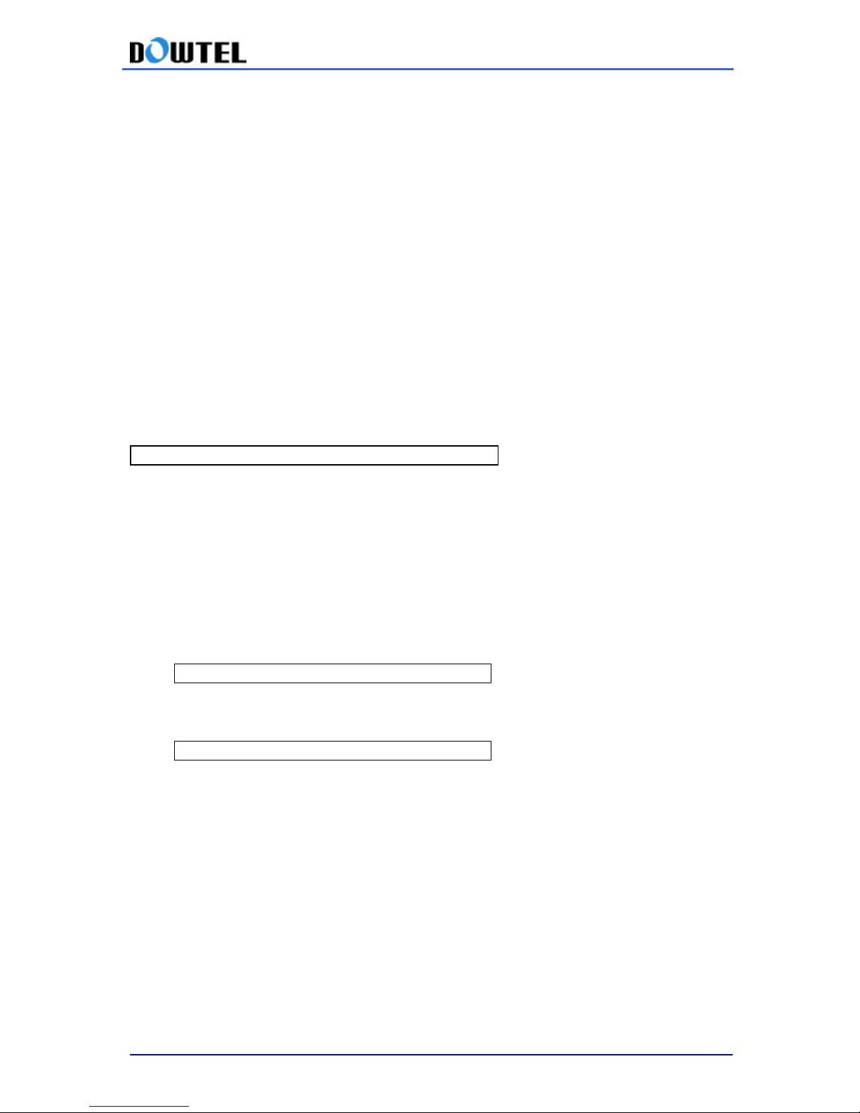
① Enter #0*100à8àMaintenance Codeà6
② If you press <1> for 8K EVRC, <5> for 13k loop,
<2> for 13K Qcelp, <6> for old 8k Markov,
<3> for 8K Qcelp, <7> for 8k Markov,
<4> for 8k loop, <8> 13k Markov
③ Press <*> button to save the setting.
#0*100à8àMaintenance Codeà7à1~8à *
Page 32
WS-2100/4100 Operating Manual
32
4.5.8 Auto Dial Send Time Control
Auto Dial Send is a function that makes a call to the dialed number after specified time lapses.
Terminal starts making a call, specified seconds after user finishes dialing the number.
Auto dial send time is adjustable from 4 seconds to 8 seconds and default setting is 6 sec.
2 se tting methods are provided below.
◆ Auto Dial Send Time Setting
1) Using A Menu Code
① Enter #0*100 à 8 à Maintenance Codeà8
② Press any number among 4 , 5 , 6 , 7 , 8 on the key pad. For example, if you press <5> key, the
send waiting time becomes 5 seconds.
③ Press <*> button in succession.
#0*100 à 8 à Maintenance Codeà 8 à 4~8 à *
4.5.9 PCO Frequency Setting
This terminal supports the Metering Pulse and the Polarity Reverse for the PCO Interface.
If the Metering Pulse is required for the PCO Interface, 2 kinds of frequencies ca n be
supported.
1) Setting Metering Pulse Frequency to 12KHz
#0*100à8àMaintenance Codeà9à1à *
2) Setting Metering Pulse Frequency to 16KHz
#0*100à8àMaintenance Codeà9à2à *
4.5.10 PRL select (Only applicable to WS-2100)
This is a cruc ial function to decide the source of Channel information when the phone
searches for CDMA Cellular Channel.
Prefer Roaming List which is being used in CDMA PCS Channel Searching can be
partially used in Cellular Channel Searching too.
If “Enable ” is selected, channel information necessary for Cellular Channel Searching
is brought from Prefer Roaming List.
If “Disable ” is selected, the original Channel Searching Method is proceeded. In other
words, it searches for CDMA Primary A/B, Secondary A/B channel.
[Note] This phone supports Prefer Roaming List stated in accordance with IS-683A.
Page 33
WS-2100/4100 Operating Manual
33
[Note] As the mal-operation with this terminal while referring to this manual may cause the terminal
impossible to acquire the system, it should be carefully operated and advance consult with a
terminal supplier is required.
1) Setting PRL select to “Enable” mode
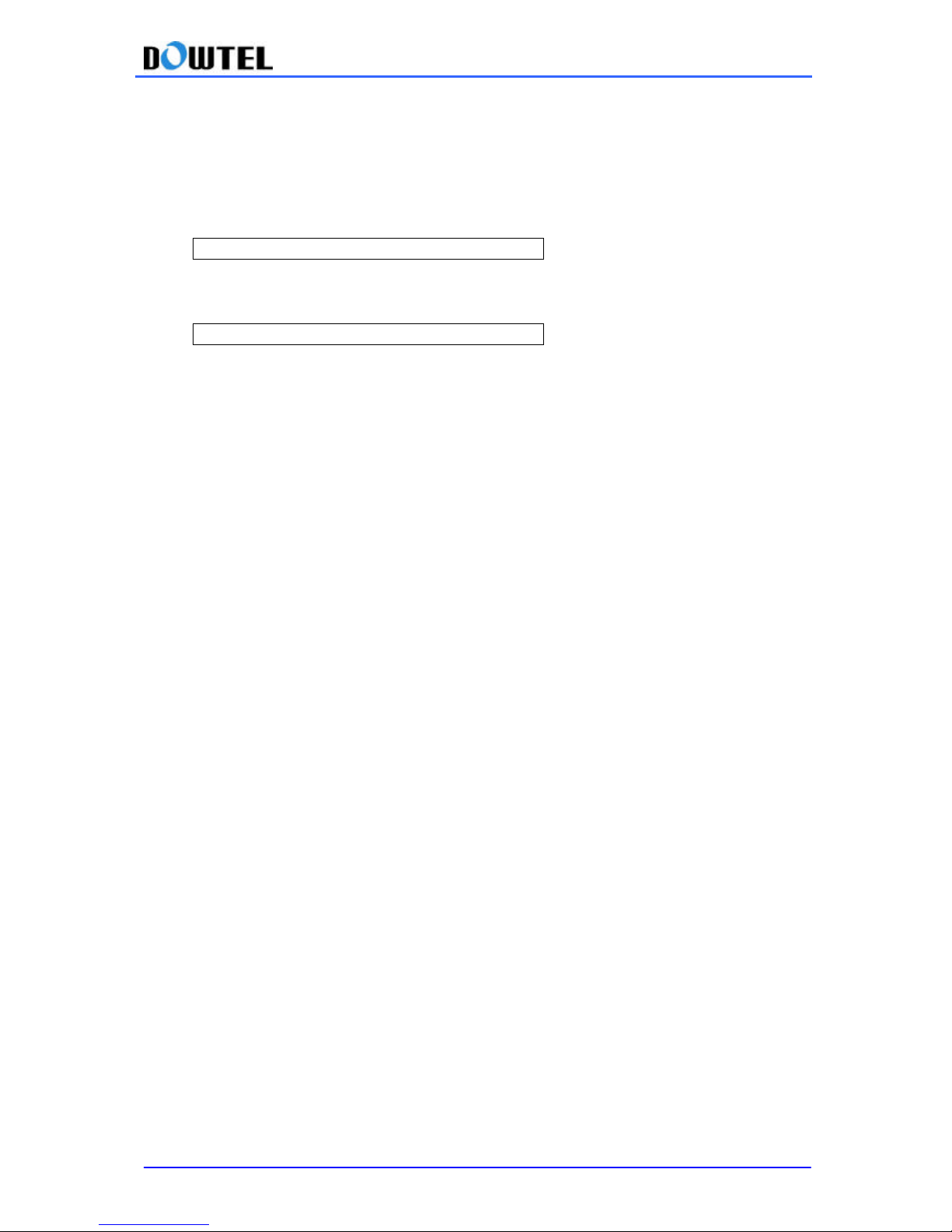
#0*100à8àMaintenance Codeà0à1à *
2) Setting PRL select to “Disable ” mode
#0*100à8àMaintenance Codeà0à2à *
Page 34
WS-2100/4100 Operating Manual
34
4.6 System Parameter Setup
Every point on the System Parameter setup is much important enough to determine the
possibility for this terminal ’s service. In particular, because the terminal (WS-2100/4100)
does not have the display module, there is no way to check the parameter setup procedure.
Therefore, in case of changing parameters, a careful reference on this chapter is required.
[Note] In case of changing the System Parameter, this terminal re -operates through the
power on/off by occasional necessity. This is the procedure to secure the best acquisition of
the system by changing parameters . But, for the change of A-Key and System Preference, the
terminal re-operation is not needed.
[Note] If the wrong key input was done while inputting the System Parameter, the terminal
transmits the Error tone of #1.3.9. In this case, if the handset is hung up, the previous key
input shall be discarded.
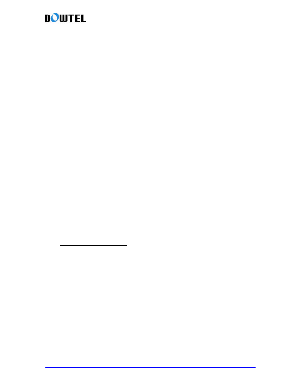
4.6.1 Phone Number (MIN) Input
This terminal features the direct MIN input by using the telephone, among system parameters.
The method of MIN input is shown below.
① Press #0*901à1 in order
② Enter MIN. Up to 10 digits can be input as MIN.
③ Press <*> button to finish
#0*901à1àMIN No.à *
If a user wants to delete the saved phone number, he or she can skip above procedure ②
and just press <*>. The procedure is as below.
#0*901à1à *
4.6.2 Directory Number Input
This method shows how to input the Mobile Directory Number into the terminal by using the
telephone.
① Press #0*901à2 in order
② Input MIN. Up to 10 digits can be input as MIN.
③ Press <*> button to finish
Page 35
WS-2100/4100 Operating Manual
35
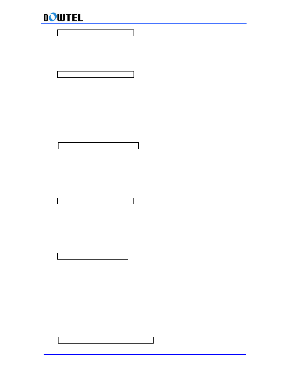
#0*901à2àDirectory No.à *
If a user wants to delete the saved Directory Number, he or she can skip above procedure ②
and just press <*>. The procedure is as below.
#0*901à2àDirectory No.à *
[Note] Mobile Directory Number is allow ed up to 15 digits.
4.6.3 Country Code (MCC) Input
① Press #0*901à3 in order
② Enter 3 digits of MCC
③ Press <*> button to save
#0*901à3àMCC(3 digits)à *
4.6.4 Network Code (MNC) Input
① Press #0*901à4 in order
② Enter 2 digits of MNC
③ Press <*> button to save
#0*901à4àMNC(2digits)à *
4.6.5 Slot Cycle Index Input
① Press #0*901à5 in order
② Input the Slot Cycle Index to use
③ Press <*> button to save
#0*901à5àSCI(1digit)à *
4.6.6 A-Key Input
This terminal supports OTASP. The authentication procedure is required for this OTASP
service and this is the function about how to input A-Key value which is essential for this
authentication procedure. The terminal does not go through power on/off after this menu
setting.
① Press #0*901à6 in order
② Input 26 digits of A Key value
③ Press <*> button to save
#0*901à6àA Key No.(26 digits)à *
Page 36
WS-2100/4100 Operating Manual
36
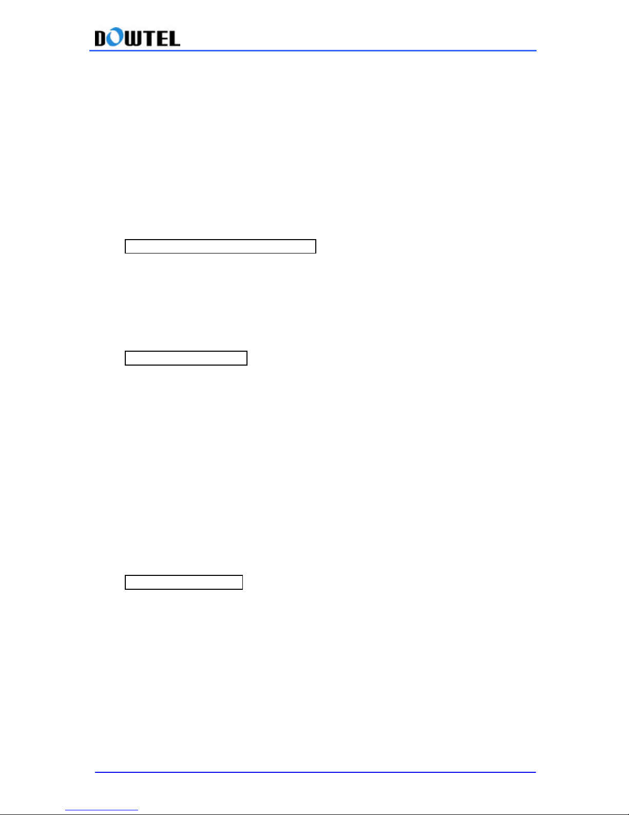
4.6.7 SID/NID Input & Delete
[Note] If the terminal in use now is WS-2100, this menu appears only if PRL function in 4.5.10
PRL Select is set to Disable.
1) SID/NID Input
① Press #0*901à7 in order
② Select 1~4 to input or change SID_NID Pair
③ After inputting SID value, press <*> button
④ After inputting NID value, press <*> to finish
#0*901à7à1~4àSIDà * NIDà *
2) SID/NID Delete
① Press #0*901à7 in order
② Select 1~4 to delete SID_NID
③ Press <*> button to finish
#0*901à7à1~4à *
4.6.8 System Preference
[Note] If the terminal in use now is WS-2100, this menu appears only if PRL function in 4. 5.10
PRL Select is set to Disable.
① Press #0*901à8 in order
② Enter <1> for “Home Only ” or <2> for “Home Pref” selection
③ Press <*> button to finish
#0*901à8à1/2à *
4.6.9 Channel Input & Delete (Only applicable to WS-2100)
[Note] This menu comes on only if RPL function in 4.5.10 PRL Select is set to Disable
and this menu is not applied to WS-4100.
1) Channel Input
① Press #0*901à9 in order
② Select 1~4 to input or change channel
Page 37
WS-2100/4100 Operating Manual
37
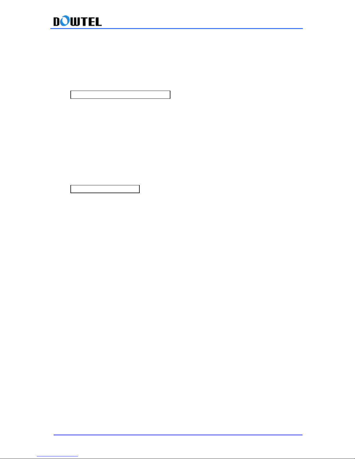
1 : CDMA Primary A Channel
2 : CDMA Primary B Cha nnel
3 : CDMA Secondary A Channel
4 : CDMA Secondary B Channel
③ Input channels
④ Press <*> button to finish
#0*901à9à1~4àChannel à *
2) Channel Delete
① Press #0*901à9 in order
② Select 1~4 to delete channel
1 : CDMA Primary A Channel
2 : CDMA Primary B Channel
3 : CDMA Secondary A Channel
4 : CDMA Secondary B Channel
③ Press <*> button to finish
#0*901à9à1~4à *
Page 38
WS-2100/4100 Operating Manual
38
APPENDIX
1. Summary Table- Supplementary Functions
On (Fax
receiving)
###005
Analog G3 Fax
Receiving
Off (Voice receiving)
###000
With a
regular
phone
###000
Data Service Receiving
Mode Off
With an Emulator
‘AT+ RCVMOD
= 0 ‘ à Enter Key
With a
regular phone
###001
Fax Receiving Mode
Setting (1 time)
With an Emulator
‘AT+ RCVMOD
= 1 ‘ à Enter Key
With
a regular phone
###002
Fax Receiving Mode
Setting (till Power Off)
With an Emulator
‘AT+ RCVMOD
= 2 ‘ à Enter Key
With
a regular phone
###003
Modem Receiving
Mode Setting (1 time)
With an Emulator
‘AT+ RCVMOD
= 3 ‘ à Enter K
ey With
a regular phone
###004
Modem
R
eceiving
Mode S etting (till
Power Off)
With an Emulator ‘AT+ RCVMOD = 4 ‘ à Enter Key
On #0*100
à
1 à 1 à 1 à *
Speed Dialing
Off #0*100 à 1 à 1 à 2 à *
Timed Hot Line On #0*100 à 1 à 2 à 1 à *
Immediate Hot On #0*100 à 1 à 2 à 2 à*
Hot Line
Off #0*100
à
1 à 2 à 3 à* Memory saving
#0*100
à
2 à
1 àmemory address
àphone number
à
* Deleting one
memory
#0*100
à
2 à 2 àmemory address
à
*
Phone Number Saving
& Deleting
Deleting all
addresses
#0*100
à
2 à
3 à *
Time input (1 time) #0*100 à 3 à 1 à 1 à time(4 digits, 24 hours) à *
One Time Mode #0*100 à 3 à 1 à 2 à *
Always Mode
#0*100
à
3 à 1 à 3 à *
Alarm Reminder
Alarm Off
#0*100
à
3 à 1 à 4 à * ###3
à
01
/ 02
/ 03 / 04 / 05
à
*
(01:min
ß 03:middle
à
05:max )
Ear-P
iece Volume
Control (5 levels)
#0*100
à
3 à 2 à 1~5
à
* (1~5 : level 1 ~ level 5 )
On
#0*100
à
1 à
3 à
1 à *
Voice Privacy Function
Off #0*100
à
1 à 3 à
2 à *
19,200 bps setting #0*100 à 3 à 3 à 1 à *
Setting Serial Baud
Rate
115,200 bps setting
#0*100
à
3 à 3 à 2 à * On #0*100
à
4 à password
à
1 à * Off #0*100
à
4 à password
à
2 à *
Lock
Password change
#0*100
à4à
password
à3à
new password
à* à
new
passwordà *
Default Setting #0*100 à 4 à password à 4 à *
Page 39
WS-2100/4100 Operating Manual
39
#0*100à8à Maintenance Code à1à1à* : DTMF mode on
#0*100à8à Maintenance Code à1à2à1à* : FSK Type2 mode on
#0*100à8à Maintenance Code à1à2à2à* : FSK Type1 mode on
CLIP Setting
#0*100à8à Maintenance Code à1à3à* : CLIP mode off
#0*100 à 8 à Maintenance Code à 2 à 1 à 1 / 2 à *
IS-99/707.4 PC
Fax method
1: PC Fax receiving default
2: Analog G3 receiving default
Analog G3 Fax
Standard Setting
IS-707A.7 method #0*100 à 8 à Maintenance Code à 2 à 2 à *
#0*100
à
8 à Maintenance Code
à
3 à 1 / 2 / 3 / 4
à
*
Default Rate Set
(1:
RS 1 (IS99
), 2:
RS 2 (IS99
), 3:
RS 1 (IS707.4
), 2
: Rate Set 2 (IS707.4) )
#0*100
à
8 à
Maintenance Code
à
4
à 1 / 2 / 3 (frequency)
à 1 / 2 / 3 / 4 / 5 / 6 (cadence) à *
Ringer Frequency &
Cadence Control
(Refer to Frequency 1: 16Hz 2: 20Hz 3: 25Hz / Cadence 1,2,3,4,5, 6: 4.8.2)
#0*100
à
8 à
Maintenance Code
à
5
à 1 / 2 / 3 /
4 à *
Dial Tone Frequency
Control
(1
: 350+440Hz 2: 400Hz 3: 425Hz 4:
450Hz)
#0*100 à 8 à Maintenance Code à 5 à 1 / 2 / 3 / 4 à *
Waiting Tone
Frequency Control
(1: 350+440Hz 2: 400Hz 3: 425Hz 4: 450Hz)
#0*100 à 8 à Maintenance Code à 7 à 1/ 2 / 3/ 4/ 5/ 6/ 7/ 8/ à *
Default Vocoder S.O
Selection
(1:
8K
EVRC, 2:
13K
Qcelp, 3:
8K
Qcelp
, 4: 8k lo
op,
5: 13k loop, 6: Old 8k Markov, 7: 8k Markov, 8: 13k Markov )
#0*100 à 8 à Maintenance Code à 8 à 4 / 5 / 6 / 7 / 8 à *
Auto Dial Send Time
(4: 4sec 5: 5sec 6: 6sec 7: 7sec 8: 8sec)
12KHz setting #0*100 à 8 à Maintenance Code à 9 à 1 à *
PCO Frequency
Setting
16KHz setting #0*100 à 8 à Maintenance Code à 9 à 2 à *
PRL Enable #0*100 à 8 à Maintenance Code à 0 à 1 à *
PRL Select(WS_2100)
PRL Disable #0*100 à 8 à Maintenance Code à 0 à 2 à *
(input) #0*901 à 1à MIN (10digits) à *
Phone number (MIN)
(delete) #0*901à1à *
(input) #0*901à2à MDN (Up to 15digits) à *
Directory Number
(delete) #0*901à2à *
(input) #0*901à3à MCC (3digits) à *
MCC Input
(delete) #0*901à3à *
(input) #0*901à4à MNC (2digits) à *
MNC Input
(delete) #0*901à4à *
Slot Cycle Index Input (input) #0*901à5 à Slot Cycle Index (0~7) à *
A Key Input #0*901 à 6 à “AKEY” (26 digits) à *
(input) #0*901 à 7 à SID_NID select (1~4) à SID select à * à NID select à *
SID_NID Pair
(input) #0*901 à 7 à SID_NID select (1~4)à *
System Preference #0*901 à 8 à 1(Home Only) / 2(Home Pref) à *
Page 40
WS-2100/4100 Operating Manual
40
(input) #0*901 à 9 à Channel select (1~4) à Channel input à *
Channel(WS2000 Only)
(delete) #0*901 à 9 à Channel select (1~4) à *
Page 41
WS-2100/4100 Operating Manual
41
2. Technical Specification
2.1 800MHz bandwidth
Air Interface
Common air interface standard → IS-95A/B & IS -95C(CDMA2000)
FREQUENCY → TX: 824 – 849MHz
RX: 869 – 894MHz
TX Max. Output Power → 200mW ~ 300mW
RX Sensitivity → - 104dBm below
Vocoder → 8K/13K QCELP, 8K EVRC
Channel Bandwidth → CDMA 1.25Mhz
RX Conducted Spurious → TX BAND: -61dBm below
RX BAND: -81dBm below
MOD/DEMOD → O QPSK/QPSK
Frequency Accuracy → Fo±300Hz
Battery Back-Up
Type → Ni-Cd
Capacity → 6V @ 1.7A
Talk Time → 2 Hours
Standby Time → 20Hours (at slot cycle index 1)
Connectors for Various
Service Support
RJ-11 → Standard wire -line telephone
Analog G3 Fax (Optional)
Serial port → Maintenance Purpose
Data Service Purpose (Internet, PC Fax)
Physical
Dimension (D×W×H) → 190×170×55mm
Weight (Including Backup battery) → 750g
Environmental
Operating temperature → 0 °C ~ +50 °C
Power Supply
Input Power → 100 ~ 240V, 50/60Hz
Output Power → DC 12V @ 1.3A
Accessories
Internal Antenna → Di-Pole Antenna
Power supply (SMPS)
Power Cord
Tel-line Cord
External Antenna (Optional) →10dBi Gain Directional Panel Antenna
Page 42
WS-2100/4100 Operating Manual
42
2.2 1.9GHz Bandwidth
Air Interface
Common air interface standard →J-STD-008, IS-95B & IS -95C
FREQUENCY → TX: 1850-4100MHz
RX: 1930-1990MHz
TX Max. Output Power → 200mW ~ 300mW
RX Sensitivity → - 104dBm below
Vocoder → 8K/13K QCELP, 8K EVRC
Channel Bandwidth → CDMA 1.25Mhz
RX Conducted Spurious → TX BAND: -61dBm below
RX BAND: -81dBm below
MOD/DEMOD → O QPSK/QPSK
Frequency Accuracy → Fo±150Hz
Battery Back-Up
Type → Ni-Cd
Capacity → 6V @ 1.7A
Talk Time → 2 Hours
Standby Time → 20Hours (at slot cycle index 1)
Connectors for Various
Service Support
RJ-11 → Standard wire -line telephone
Analog G3 Fax (Optional)
Serial port → Maintenance Purpose
Data Service Purpose (Internet, PC Fax)
Physical
Dimension (D×W×H) → 190×170×55mm
Weight (Including Backup battery) → 750g
Environmental
Operating temperature → 0 °C ~ +50 °C
Power Supply
Input Power → 100 ~ 240V, 50/60Hz
Output Power → DC 12V @ 1.3A
Accessories
Internal Antenna → Di-Pole Antenna
Power supply (SMPS)
Power Cord
Tel-line Cord
External Antenna (Optional) → 10dBi Gain Directional
Panel Antenna
3. Trouble Shooting
Page 43
WS-2100/4100 Operating Manual
43
In the event of a product malfunction, please check the list below for a possible solution before
contacting your local service provider.
In Case… Try This…
▶ No sound after picking up the phone ☞ Check if the terminal Power LED or Battery
LED is on. If the power is off, check if the
SMPS power plug is properly connected.
☞ Check if RJ-11 Jack is properly connected.
▶ Battery LED does not light up after the AC
power is gone
☞ Check to make sure the Terminal’s Power
Switch is ON.
▶ When the Service LED blinks or down. ☞ Check if the antenna is correctly connected
or change the terminal location for better signal
strength.
▶ When you hear the Warning Tone instead of
the Dial tone after picking up the phone
☞ Check if the antenna is correctly connected
and or change the terminal location for better
signal strength.
▶ When you attempt a call and hear
the
Warning Tone. Example “Beep beep”
☞ This means no call channel is available or
there is a communication failure with the base
station.
☞ Check if the Service LED is on and try to
make a call again.
▶ When the call does not go through, and
there is a Warning Tone, but you can receive
calls.
☞ Probably The Lock Function is on.
Refer to Section 4.4 of the Manual
☞ If you do not know the Lock Code, consult
your distributor or your local service center.
▶ A voice echo during conversations. ☞ The echo removing function of the base
station is incorrectly set.
Refer to Section 4.3.2 of the Manual and
adjust the volume.
▶ The other party’s voice is faint. ☞ Refer to Section 4.3.2 and adjust the
volume.
▶ Battery LED blinks or goes off when in the
back up battery is in use.
☞ The Backup Battery Power is very low or
being discharged, so re-charged Battery
with SMPS
※ If the problem you are experiencing persists or is not mentioned above, please contact
your local distributor or service center. M
Page 44

WS-2100/4100 Operating Manual
1
Safety Information
1 . SAFETY INFORMATION FOR FIXED WIRELESS TERMINALS
.POTE NTIALLY EXPLOSIVE AT MOSPHERES
Turn your phone OFF when in any area with a potentially explosive atmosphere and
obey all signs and instructions. Sparks in such areas could cauls e an explosion or fire
resulting in bodily injury or even death.
.
INTERFERENCE TO MEDICAL DIVICES
Certain electronic equipment may be shielded against RF signal from you wireless
phone. (pacemakers, Hearing Aids, and so on)
Turn your phone OFF in health care facilities when any regulations posted in these
areas instruct you to do so.
RF signals may affect improperly installed or inadequately shielded electronic system
in motor vehicles.
.EXPOSURE TO RF ENERGY
Use only the supplied or an approved replacement antenna.
Do not touch the antenna unnecessarily when the phone is in use.
Do not move the antenna close to, or touching any exposed part of the body when
making a call.
Page 45

WS-2100/4100 Operating Manual
2
SAR INFORMATION
THIS MODEL PHONE MEETS THE GOVERNMENT ’S REQUIREMENTS FOR
EXPOSURE TO RADIO WAVES.
Your wireless phone is a radio transmitter and receiver. It is designed and anufactured not to
exceed the emission limits for exposure to radio frequency (RF)energy set by the Federal
Communications Commission of the U.S.Government.These limits are part of comprehensive
guidelines and establish permitted levels of RF energy for the general population. The guidelines
are based on standards that were developed by independent scientific organizations through
periodic and thorough evaluate on of scientific studies. The standards include a substantial safety
margin designed to assure the safety of all persons, regardless of age and health.
The exposure standard for wireless mobile phones employs a unit of measurement
known as the Specific Absorption Rate, or SAR. The SAR limit set by the FCC is 1.6
W/kg.*Tests for SAR are conducted with the phone transmitting at its highest certified
power level in all tested frequency bands. Although the SAR is determined at the
highest certified power level, the actual SAR level of the phone while operating can be
well below the maximum value. This is because the phone is designed to operate at
multiple power levels so as to use only the power required to reach the network. In
general, the closer you are to a wireless base station antenna, the lower the power
output. Before a phone model is available for sale to the public, it must be tested and
certified to the FCC that it does not exceed the limit established by the governmentadopted
requirement for safe exposure.
The tests are performed in positions and locations (e.g., at the ear and worn on the body) as
required by the FCC for each model. The highest SAR value for this model phone when worn on
the body, as described in this user guide, is 1.10 W/kg. (Body worn measurements differ among
phone models, depending upon available accessories and FCC requirements). While there may be
differences between the SAR levels of various phones and at various positions, they all meet the
government requirement for safe exposure. The FCC has granted an Equipment Authorization for
this model phone with all reported SAR levels evaluated as in compliance with the FCC RF
exposure guidelines. SAR information on this model phone is on file with the FCC and can be
found under the Display Grant section of http://www.fcc.gov / oet / fccid after searching on
FCC ID : PV4WS-2100.
Additional information on Specific Absorption Rates (SAR)can be found on the Cellular Telecommunications
&Internet Association (CTIA)web-site at http://phonefacts.net.*In the United States and Canada, the SAR limit for
mobile phones used by the public is 1.6watts/kg (W/kg)averaged over one gram of tissue. The standard
incorporates a substantial margin of safety
to give additional protection for the public and to account for any agitations in measurements.
Page 46

WS-2100/4100 Operating Manual
FCC RF EXPOSURE INFORMATION
In August 1996 the Federal Communications Commission (FCC) of the United States with its action in
Report and Order FCC 96-326 adopted an updated safety standard for human exposure to radio frequency
(RF) electromagnetic energy emitted by FCC regulated transmitters. Those guidelines are consistent with the
safety standard previously set by both U.S. and international standards bodies. The design of this phone
complies with the FCC guidelines and these international standards.
To comply with FCC RF exposure requirements, a minimum separation distance of 2.5cm (0.98 inch) must
be maintained between the user/ bystander and the back of the unit, including the antenna.
For more information about RF exposure, please visit the FCC website at www.fcc.gov
WARNING! Read this information before use
Page 47

WS-2100/4100 Operating Manual
3
FCC Compliance Information
This device complies with Part 15 of FCC Rules.
Operation is subject to the following two conditions:
(1) This device may not cause harmful interference, and
(2) This device must accept any interference received.
Including interference that may cause undesired operation.
Information to User
This equipment has been tested and found to comply with the limits for a Class B digital
device, pursuant to part 15 of the FCC Rules. These limits are designed to provide reasonable
protection against harmful interference in a residential installation. This
equipment generates, uses and can radiate radio frequency energy and, if not installed
and used in accordance with the instructions, may cause harmful interference to radio
communications. However, there is no guarantee that interference will not occur in a particular
installation. If this equipment does cause harmful interference to radio or television reception,
which can be determined by turning the equipment off and on, the user is encouraged to try to
correct the interference by one or more of the following measures:
- Reorient or relocate the receiving antenna.
- Increase the separation between the equipment and receiver.
- Connect the equipment into
an outlet on a circuit different from that to which the
receiver is connected.
- Consult the dealer or an experienced radio/ tv technician for help.
 Loading...