


09/01/16
All business
No bullsh*t
All business
No bullsh*t
SPRINT GATE SOLAR
DOUBLE GATES
IMPORTANT
Read this manual before starting install
INSTALL
MANUAL

WELCOME!
Fed up with all the u found in manufacturer’s instructions? The backbone
of Short Cuts manuals is short and snappy info to get the best results fast.
Produced in-house by the team at Downee, Short Cut manuals are created
using plain English and our own real-world install experiences. We’ve chopped
o the fat leaving only the meaty bits you need to get a gate system rocking in
record time.
Don’t feel like reading? No worries! Video versions of Short Cut manuals are
in the Tech Area page for this motor on our website.
PAGE
INDEX
Gates
Motor Position
Brackets
Battery Box
Solar Panel Post
Solar Panel
Stop Limits
Power Up Motor One
Connect Motor Two
Programming
Connect the Remote
2
2
3
4
4
5
5
6
7
8
9
Video instructions of
this manual are on
our website.
TROUBLESHOOTING
Connect the Aerial
Accessories
Solar Controller
Call our Tech Team
1800 241 733
9
10
11

3
KIT
4
PARTS
5
8
1 2
6 6
1
Motor One
24V Motor with
Control Board
7 7
2
Motor Two
24V Motor
Ziggy
Remotes
3
Booster
Aerial
4
30W Solar
8
Battery Box
security key
Panel
with high
5
Panel
Post
Solar
Controller
6
Bracket
12V 22Ah
Batteries
Post
7
Gate Bracket
and Clamp
NOT SUPPLIED
- Angle Brackets for
Battery Box
- Gate Post Cap for
Panel Post
- Tek Screws
- 2-Core Cable
1
1

GATES
CODE: S8-AT
CODE: G7-BBAT
Check gates are in excellent operating condition. Gates in poor operation will
give you trouble and prematurely wear out.
DELUXE HINGES
Gates with automation need heavy duty hinges
to handle the load. Designed for Sprint Gate,
Deluxe bearing hinges are the nest farm
gate hinges available anywhere.
MOTOR POSITION
TIPS
These steps apply to both motors
A
Best position for a Motor is halfway up the Gate Post.
B
1. Close the gates.
2. Extend Motor Arms.
3. Hold Motor on the gate post where the Arm meets the Gate Stay.
If there’s no stay, mount on the gate frame.
4. Mark the posts at the bottom of the Motor.
2
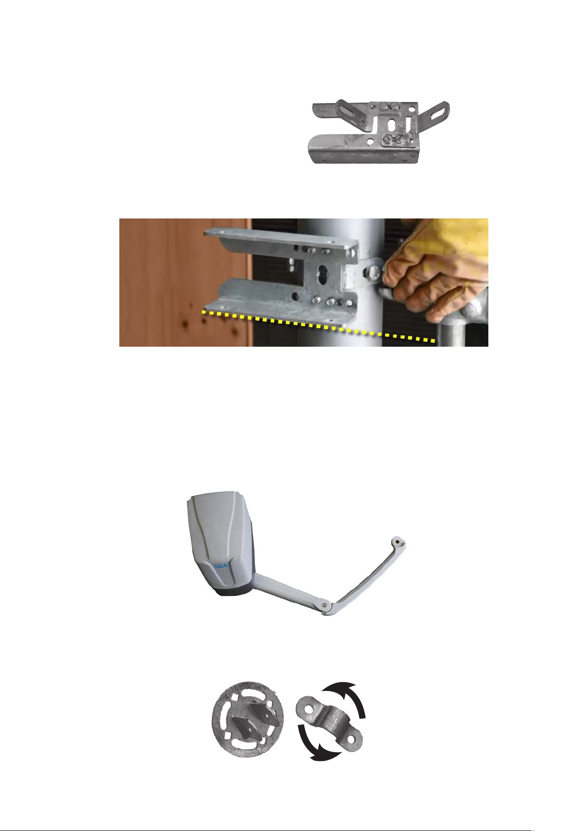
BRACKETS
1. Adjust the Post Brackets to t the
Gate Post width and tighten.
GATE THIS
SIDE >>>>
2. Mount Post Bracket with bottom edge on the mark. (#4 previous page)
3. Remove a Top Cover o a motor to nd which one houses the
electronic Control Board.
4. Bolt both Motors to Post Brackets
5. Bolt the Arms to Motors. Pin the thin arm Arm onto the thick arm.
The thin arm ts left or right hand gates.
6. Pin the Universal Gate Bracket to the Thin Arm and mount
it to the gate stay. The bracket clamp rotates to t any angle.
3

BATTERY BOX
NOTE
Post Brackets are not supplied with Sprint
Gate Kits. Two pieces of angle will do.
1. Work out where the Battery Box will sit above Motor One.
2. Start with the bottom Post Bracket and mount it
to Gate Post.
3. Attach the other angle bracket to the top
mount on the battery box. Sit the Box on
the bottom angle and attach the top angle
to the Gate Post.
4. Use the key to open the box and remove the foam blocks.
SOLAR PANEL POST
NOTE
TIP
1. Drill a hole in the centre of the post cap and bolt it
onto the Panel Post.
2. Place the Cap & Post onto the top of the gate post.
It may be a tight and may need some gentle
encouragement with a hammer. Keep it in place
with self tappers or tek screws.
Steel Post Cap not supplied in this kit. Measure the
diameter of your gate post to match a Post Cap.
Position the bolt holes east-west for the solar panel to face north. Not
sure which direction north sits? Download a free compass app onto
your smart phone.
Keep the carton containing the solar panel in good condition. You’ll
need it a bit later.
4
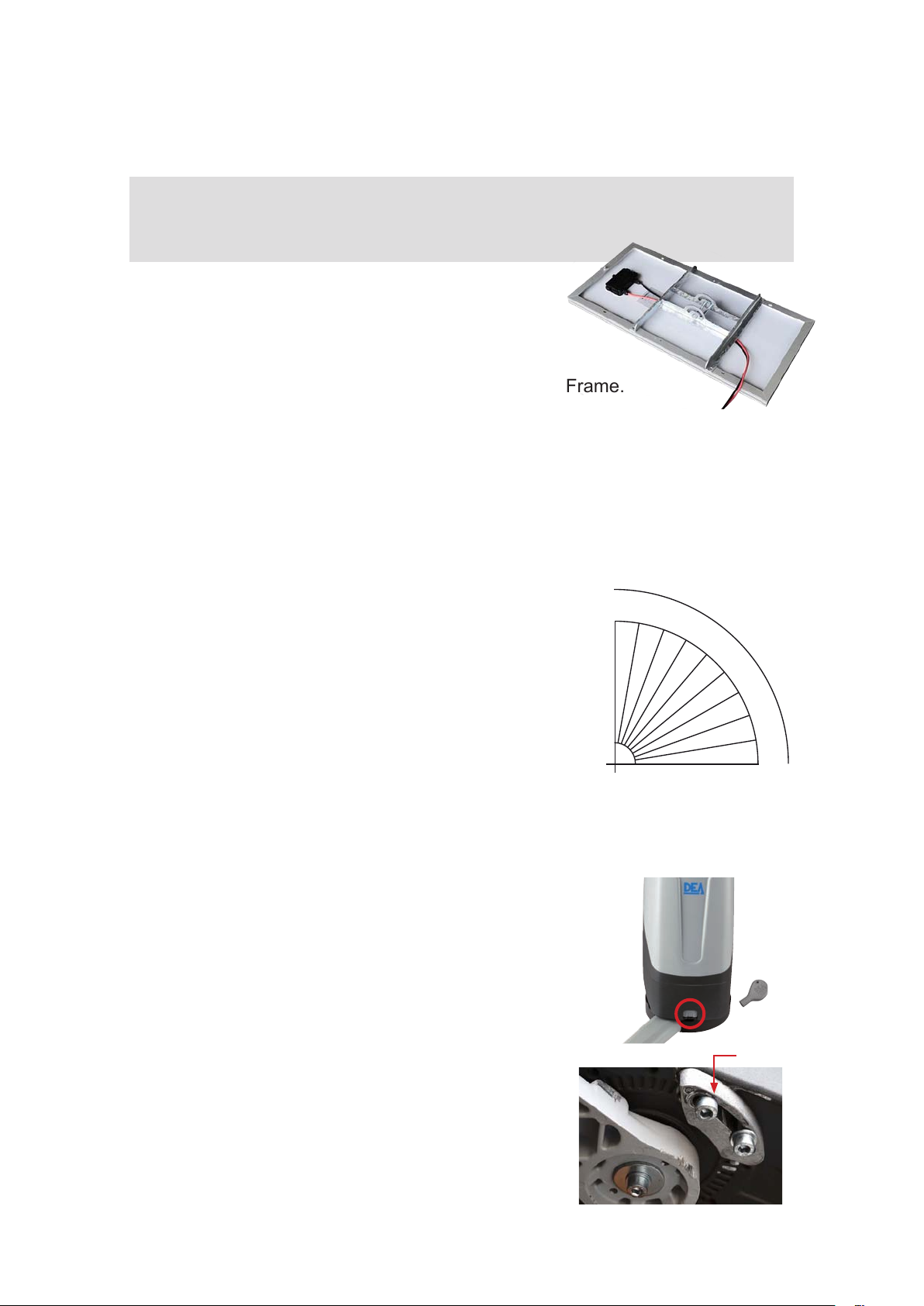
SOLAR PANEL
TIP If the gate is shaded through the day, position the Solar Panel away
from the gate.
1. Using Tek screws mount Panel Bracket to the
Solar Panel.
2. Tek screw the Aerial on top of the Solar Panel Frame.
3. Bolt the Solar Panel (facing north) to the Panel Post. Leave the carton
covering the Panel.
PANEL ANGLE
Setting the solar panel’s angle to suit the location
90
will give maximum charging rate.
Tasmania 40˚
Melbourne 38˚
Sydney 35˚
Canberra 35˚
Adelaide 34˚
Perth 31˚
Brisbane 27˚
Darwin 12˚
80
70
60
50
40
30
20
10
0
Dierent location? Refer to table on page 12.
STOP LIMITS
1. Use the Motor Key to unlock the Motor Arm.
2. Close the gate. Bolt a Stop in place where
the Arm will sit against it when closed.
3. Open the gate and add a Stop for the
gate’s open position.
4. Adjust as needed then tighten all bolts.
Key
Stop
5
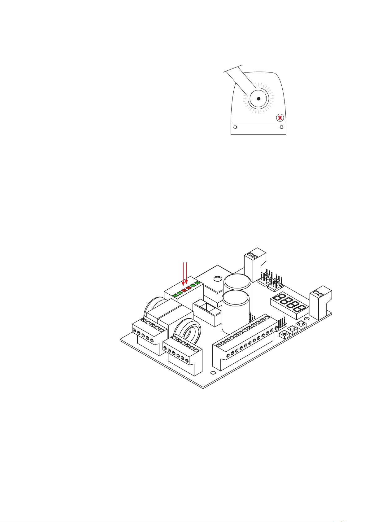
POWER UP MOTOR ONE
1. Remove the Motor cover and the inner control
board cover.
2. Use a screwdriver to punch a hole in the cable
entry point provided (right).
Bottom View
3. Run the battery cable from Battery Box to motor via the new hole.
Then divert wire to left side through the hole used to route wires in
the grey plastic base.
4. Strip the ends of the brown & blue
wires (white outer cable).
5. Remove two black wires from
the 22VAC INPUT terminals
and pull them through and
out of the way.
22VAC
INPUT
Control Board
6. Connect the brown & blue
wires from the battery into
the 22VAC INPUT terminals.
6
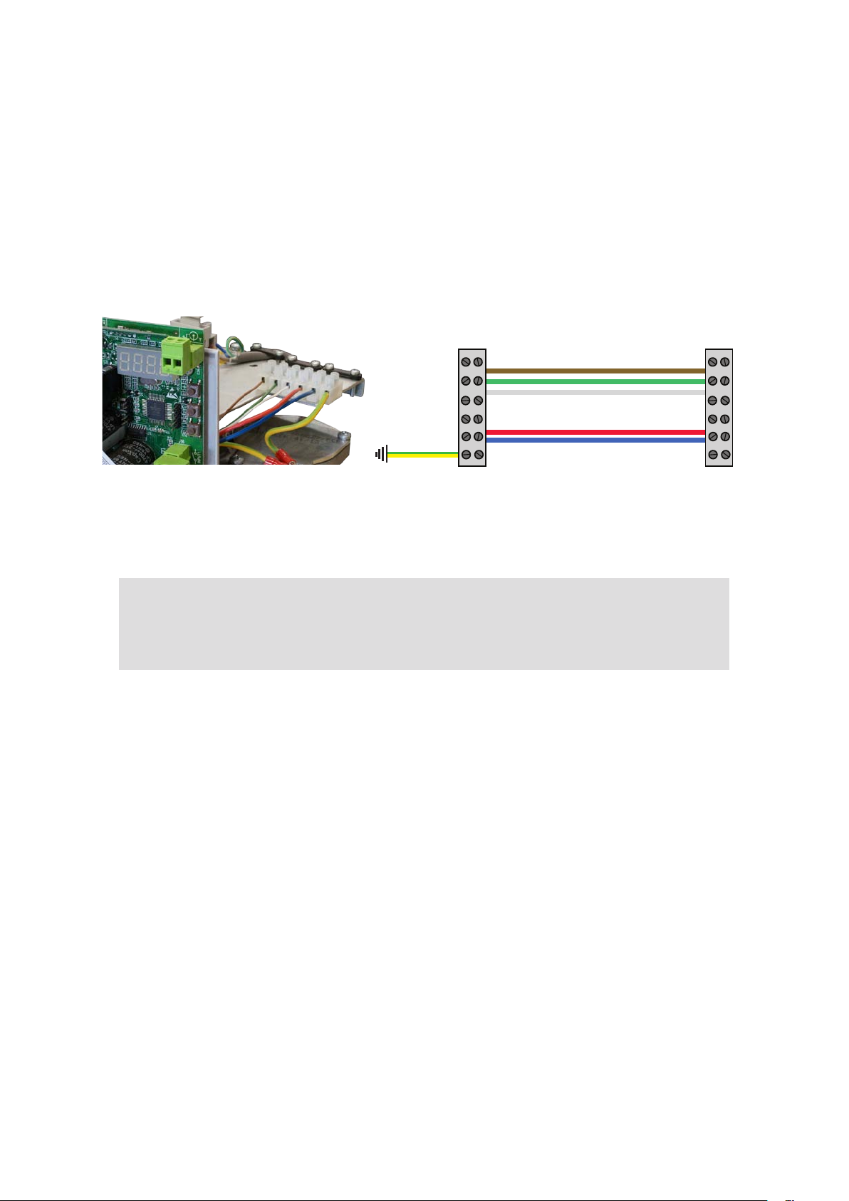
CONNECT MOTOR TWO
1. Dig a channel between motors for conduit.
2. Run the Figure-8 and 4-core cable through conduit.
3. Bury the conduit and connect the cables as shown below.
MOTOR TWO
NOTE
MOTOR ONE
4-core
gure-8
Motor One
Use 0.75mm gure-8, 2-core cable and 4-core (three used, one spare)
0.5mm cable in conduit (not supplied).
24V cable is safe to be buried at any depth.
4. Place the fuse (inside Battery Box door) into the fuse holder on the red
power cable. The batteries are fully charged so it may spark. That’s OK,
24V is completely safe.
5. With the carton still covering the solar panel, connect the black and red
power cables to the Solar Panel and Battery. The digital screen on
the motor’s control board and solar controller screen will light up.
6. Cable tie the power cables to the post.
7
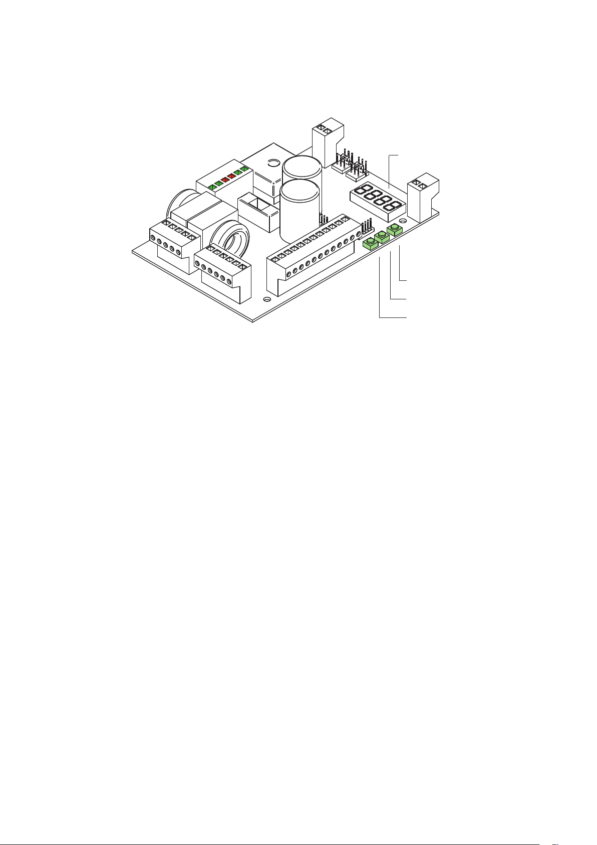
PROGRAMMING
Digital
Display
Programming
Buttons
Control Board
1. Position the gate half way between open/closed. Lock the Arm using the
Key in front of Motor.
Scroll up
OK
Scroll down
2. Using the buttons (above) on the Control Board, Scroll to P030 & press
OK
3. Scroll to d002 & press OK. Display will show P030
4. Scroll to P003.
5. Press middle button once (1) APPr ashes.
6. Press & hold the middle button till APPr stops ashing.
7. The gate will fully open & close automatically to nd where the Stops
are placed. The gate should nish in the closed position.
8. This symbol is for ‘Gate Closed’. It shows on screen when
done.
_| |_ If you see this, the ‘Gate Open’ symbol, swap the brown and blue
wires between the terminals.
_ _ _ _
PROGRAMMING IS FINISHED!
8
CONNECT THE REMOTE
1. Scroll to P005 & press OK
2. When LEAr shows press the
remote button.
r000 shows a remote is connected.
Repeat step 2 for extra remotes as needed.
r001 shows when a second remote is connected.
r010 shows when the tenth remote is connected etc. etc.
3. Wait 10sec. for the (- - - -) symbol to conrm memory
process is complete.
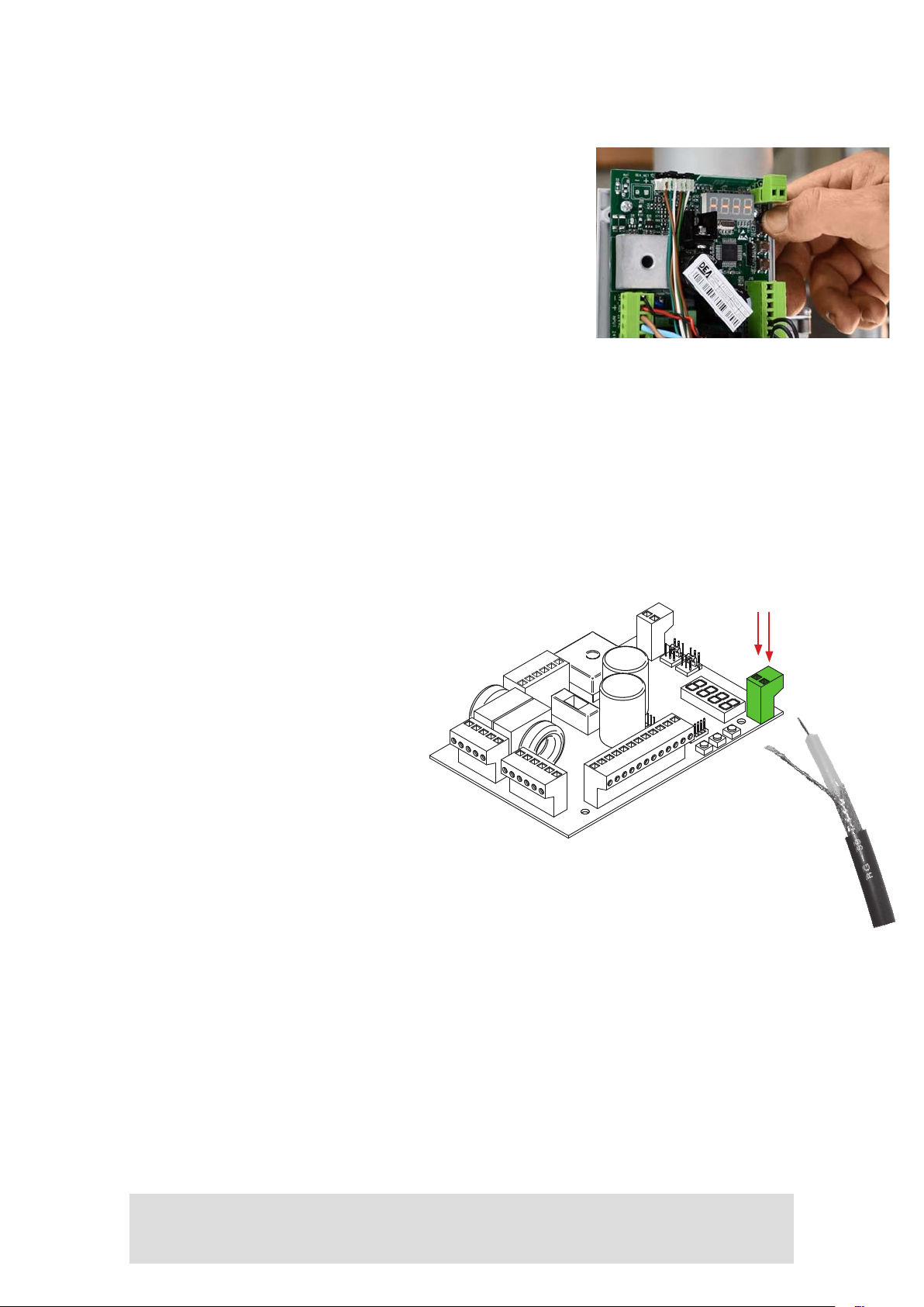
CONNECT THE AERIAL
1. Thread aerial cable via the hole under the motor.
2. Strip the outer cable approx. 50mm.
Separate the inner & outer wires.
Twist the outer wire.
3. Strip end o the clear inner
insulation. Trim wires so both
are same length.
4. Attach wires to the Control
Board (shown).
PUT IN SOLAR MODE
1. Scroll to P061 & Press OK
2. Change parameter to d001.
Aerial
Terminals
Control Board
3. Scroll back to (- - - -)
4. Test Remote Control operates gate. If it works just ne, replace the
Control Board Cover and Motor Cover cos you’re done!
NOTE: when is solar mode, the LCD will turn o and blink once every 10 seconds
Something not working the way it should?
SOS
Call our Tech Team
1800 241 733
9
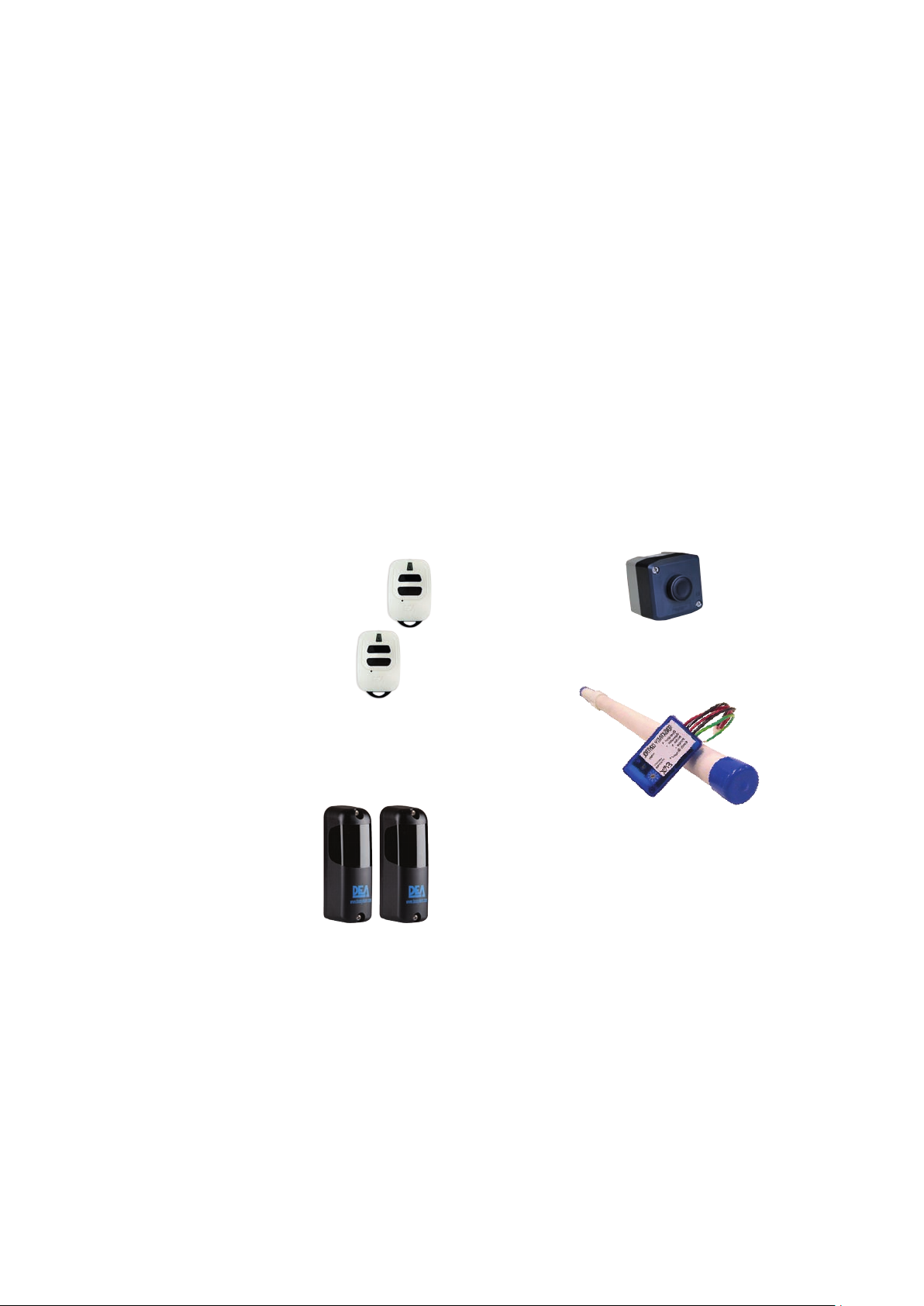
ACCESSORIES
The standard Sprint Gate is operated with remote controls. Other accessories
can quickly and easily be added to automate its open/close function such as
visitor control, automatic exit, improved security, control via mobile phones, and
more.
However, more accessories will drain the batteries, so also consider upgrading
your solar system to a larger panel or bigger battery bank.
SOME OF THE ACCESS CONTROL ACCESSORIES AVAILABLE
For more information see Access Control in the products menu on our website.
ZIGGY REMOTE
Need extra Remotes?
Easy to connect in just a
few steps (see instructions).
Designed in Italy.
PHOTOCELLS
Stop the gate when an
obstacle is detected.
OPEN/CLOSE
CONTROL
For visitors exiting
the property.
EXIT SENSOR
A single piece motion
sensor buried under or beside
the driveway. Exit Sensor detects
a car approaching from inside
the property, automatically
opening the gate. Simple
plug-n-play connection.
10
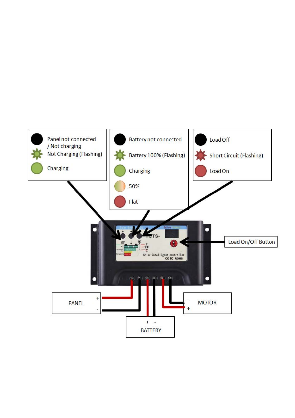
SOLAR CONTROLLER
Cover the panel from the sun when connecting panel to controller.
Always turn o the load before connecting to the motor.
The controller automatically detects system voltage based on battery voltage. If the
batteries are too low, the controller will think it is a 12V system. When this happens,
the controller will not charge the batteries.
No power to motor!
• Check fuses and connections
• If short-circuit or overload, press Load On/O button and wait 30 seconds.
• Check individual battery voltage. If under 11.1V, remove batteries and recharge
using car battery charger.
11

SOLAR
ANGLES
Notes:
On the 21st December,
the sun will rise 109°
east of due north and
set 109° west of due
north.
On the 21st March/21st
September, the sun
will rise 91° east of due
north and set 91° west
of due north.
On the 21st June, the
sun will rise 73° east of
due north and set 73°
west of due north.
12
City Winter Spring/Autumn Summer
Adelaide 32° 55° 78°
Albany 32° 55° 78°
Albury 30° 54° 78°
Alice Springs 42° 66° 90°
Armidale 36° 60° 84°
Ballarat 28° 52° 76°
Banora Point 38° 62° 86°
Bendigo 30° 53° 76°
Blacktown 32° 56° 80°
Brisbane 38° 62° 86°
Broken Hill 34° 58° 82°
Brunswick 28° 52° 76°
Buderim 40° 63° 86°
Bunbury 34° 57° 80°
Bundaberg 42° 65° 88°
Burnie 26° 49° 72°
Caboolture 40° 63° 86°
Carins 50° 73° 96°
Caloundra 40° 63° 86°
Canberra 32° 55° 78°
Canning Vale 34° 58° 82°
Carindale 38° 62° 86°
Caringbah 32° 56° 80°
Carlingford 32° 56° 80°
Castle Hill 32° 56° 80°
Cessnock 34° 57° 80°
City of Parramatta 32° 56° 80°
Cos Harbour 36° 60° 84°
Craigieburn 28° 52° 76°
Cranbourne 28° 52° 76°
Cronulla 32° 56° 80°
Darwin 54° 78° 102°
Deception Bay 40°
Dee Why 32° 56° 80°
Devonport 26° 49° 72°
Dubbo 34° 58° 82°
Earlwood 32° 56° 80°
Echuca 30° 54° 78°
Engadine 32° 56° 80°
Epping 32° 56° 80°
Ferntree Gully 28° 52° 76°
Forster 34° 58° 82°
Frankston East 28° 52° 76°
Gawler 32° 55° 78°
Geelong 28° 52° 76°
Geraldton 38° 61° 84°
Gladstone 42° 66° 90°
Glenmore Park 32° 56° 80°
Gold Coast 38° 62° 86°
Gosnells 34° 58° 82°
Goulburn 32° 55° 78°
Granville 32° 56° 80°
Greensborough 28° 52° 76°
Grith 32° 56° 80°
Hobart 24° 47° 70°
Hoppers Crossing 28° 52° 76°
Hornsby 32° 56° 80°
Jervis Bay Village 32° 55° 78°
63° 86°
City Winter Spring/Autumn Summer
Kalgoorlie 36° 59° 82°
Katoomba 32° 56° 80°
Kwinana 34° 58° 82°
Launceston 26° 49° 72°
Lismore 38° 61° 84°
Liverpool 32° 56° 80°
Logan City 38° 62° 86°
Mackay 46° 69° 92°
Mandurah 34° 57° 80°
Maroubra 32° 56° 80°
Marrickville 32° 56° 80°
Maryborough 40° 64° 88°
Melbourne 28° 52° 76°
Melton 28° 52° 76°
Mildura 32° 56° 80°
Mooloolaba 40° 63° 86°
Mornington 28° 52° 76°
Morphett Vale 32° 55° 78°
Mosman 32° 56° 80°
Mount Gambier 28° 52° 76°
Mount Isa 46° 69° 92°
Murray Bridge 32° 55° 78°
Nerang 38° 62° 86°
Newcastle 34° 57° 80°
North Shore 36° 59° 82°
Nowra 32° 55° 78°
Orange 34° 57° 80°
Palmerston 54° 78° 102°
Paramatta 32° 56° 80°
Perth 34° 58° 82°
Port Macquarie 36° 59° 82°
Port Stephens 34° 57° 80°
Quakers Hill 32° 56° 80°
Queanbeyan 32°
Rainbow Beach 40° 64° 88°
Randwick 32° 56° 80°
Rockhampton 44° 67° 90°
Roebourne 46° 69° 92°
Shepparton 30° 54° 78°
South Brisbane 38° 62° 86°
South Grafton 36° 60° 84°
Southport 38° 62° 86°
Sunbury 28° 52° 76°
Sunnybank 38° 62° 86°
Surfers Paradise 38° 62° 86°
Sydney 32° 56° 80°
Tamworth 36° 59° 82°
Taree 34° 58° 82°
Toowoomba 38° 62° 86°
Torquay 42° 65° 88°
Townsville 48° 71° 94°
Traralgon 28° 52° 76°
Wagga Wagga 32° 55° 78°
Warrnambool 28° 52° 76°
Whyalla 34° 57° 80°
Wodonga 30° 54° 78°
Wollongong 32° 56° 80°
55° 78°
 Loading...