

Page 1
Vertical Adjustment
Locking Screw
Mounting Screw
Horizontal Adjustment
Locking Screws
Both Sides
Keeper
GATE
GATE
POST
GATE
POST
12mm
Screw
Trim Spindle Tube 11-13mm
Longer than Gate Post
Spindle Tube
MUST be fitted
Spindle
INSIDE
LATCH
CENTERLINE
OF LATCH
3/4"
SPINDLE
THRU
HOLE
GATE
FRAME
3/4"
FIG. 1
12mm
Screw
30mm
Screw
Trim Spindle Tube 11-13mm
Longer than Gate Post
Spindle Tube
MUST be fitted
Spindle Tube to be
11 to 13mm longer
than Gate Post
Spindle
INSIDE
LATCH
OUTSIDE
LATCH
CENTERLINE
OF LATCH
3/4"
SPINDLE
THRU
HOLE
GATE
FRAME
3/4"
FIG. 1
12mm
Screw
30mm
Screw
Trim Spindle Tube 11-13mm
Longer than Gate Post
Spindle Tube
MUST be fitted
Spindle Tube to be
11 to 13mm longer
than Gate Post
Spindle
INSIDE
LATCH
OUTSIDE
LATCH
CENTERLINE
OF LATCH
3/4"
SPINDLE
THRU
HOLE
GATE
FRAME
3/4"
FIG. 1
12mm
Screw
30mm
Screw
Trim Spindle Tube 11-13mm
Longer than Gate Post
Spindle Tube
MUST be fitted
Spindle Tube to be
11 to 13mm longer
than Gate Post
Spindle
INSIDE
LATCH
OUTSIDE
LATCH
MAGNET
LEVER
DPLLEVER
MAGNET
LEVER
LATCH
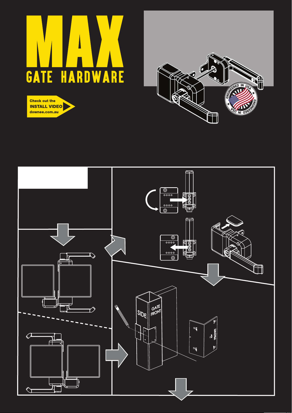
- Suits 40 - 125mm Posts
- Left or Right Handed
- Single or Double Gates
- Lock/Unlock Both Sides
DPLLEVER
START
Left or
Right?
The Latch comes ready
for Right-Handed gates. A
few simple steps and the
Latch is ready for
Left-Handed gates.
To change the
Latch for
left-handed
install.
Slide Keeper
off the
Mount and
rotate it
180° degrees.
LATCH
- Suits 40 - 125mm Posts
- Left or Right Handed
- Single or Double Gates
- Lock/Unlock Both Sides
Mount
Keeper
Slide bottom cover
out of Latch.
Slide it into the top.
LEFT
POST
RIGHT
GATE
GATE
POST
Mark Latch
position
on SIDE
of gate
FRONT
template
Use both FRONT and
BACK templates to mark
the mounting holes.
Drill a Ø19mm hole at
the centre (marked 3/4”)
on the both
templates.
Drill the Ø3mm pilot
holes (marked 1/8”)
at each corner of the
template.
08/09/16
Page 2
CENTERLINE
OF LATCH
SPINDLE
12mm
Screw
30mm
Screw
CENTERLINE
OF LATCH
FIG. 8
.125
(1/8")
Vertical Adjustment
Locking Screw
Mounting Screw
Horizontal Adjustment
Locking Screws
Both Sides
Keeper
Mounting Screw
SHEET 3 OF 3
GATE
POST
GATE
POST
CENTERLINE
OF LATCH
3/4"
SPINDLE
THRU
HOLE
GATE
FRAME
3/4"
FIG. 1
12mm
Screw
30mm
Screw
Trim Spindle Tube 11-13mm
Longer than Gate Post
Spindle Tube
MUST be fitted
Spindle Tube to be
11 to 13mm longer
than Gate Post
Spindle
INSIDE
LATCH
OUTSIDE
LATCH
CENTERLINE
OF LATCH
3/4"
SPINDLE
THRU
HOLE
GATE
FRAME
3/4"
FIG. 1
12mm
Screw
30mm
Screw
Trim Spindle Tube 11-13mm
Longer than Gate Post
Spindle Tube
MUST be fitted
Spindle Tube to be
11 to 13mm longer
than Gate Post
Spindle
INSIDE
LATCH
OUTSIDE
LATCH
CENTERLINE
OF LATCH
3/4"
FIG. 1
12mm
Screw
30mm
Screw
Trim Spindle Tube 11-13mm
Longer than Gate Post
Spindle Tube
MUST be fitted
Spindle Tube to be
11 to 13mm longer
than Gate Post
Spindle
INSIDE
LATCH
OUTSIDE
LATCH
CENTERLINE
OF LATCH
3/4"
SPINDLE
THRU
HOLE
GATE
FRAME
3/4"
FIG. 1
12mm
Screw
30mm
Screw
Trim Spindle Tube 11-13mm
Longer than Gate Post
Spindle Tube
MUST be fitted
Spindle Tube to be
11 to 13mm longer
than Gate Post
Spindle
INSIDE
LATCH
OUTSIDE
LATCH
12mm
Screw
Spindle Tube
MUST be fitted
Spindle
INSIDE
LATCH
Continued
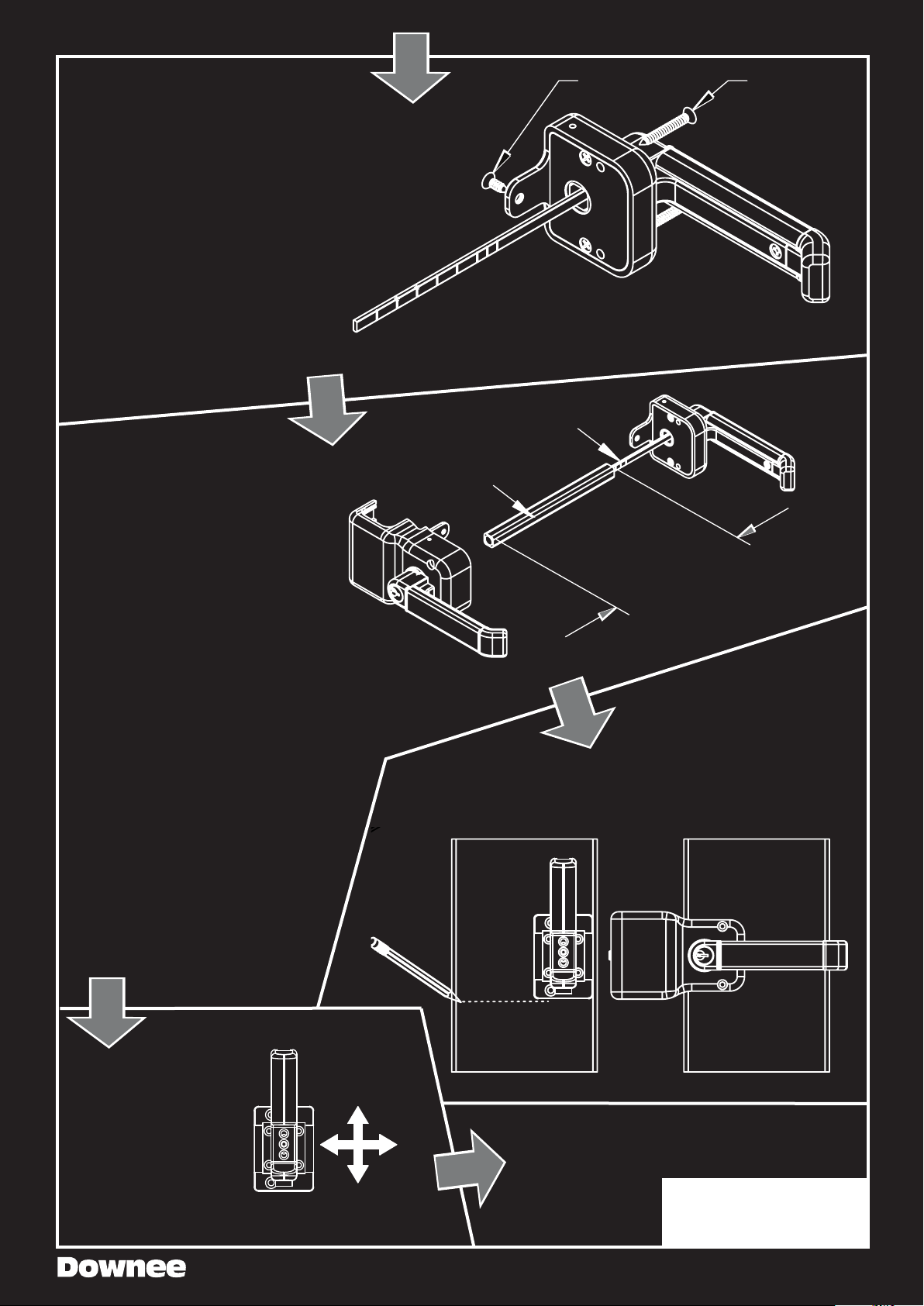
Trim Spindle
Trim both Spindles using the trim
marks.
POST (mm) TRIM MARK
40 1
45 2
50 3
75 5
90 6
100 7
125 no trim
Slide Spindle Tube over Spindle.
Secure the Inside Latch to the gate
using one 30mm screw.
Position Inside Latch over Spindle
Tube and Spindle. If the Latch sits
ush secure both Latches using all
screws.
If Inside Latch doesn’t sit ush the
Spindle Tube or Spindle may be too
long. Try this:
• Remove both Latches.
• Mount Inside Latch without
Spindle Tube.
• Hold Outside Latch against gate.
If it doesn’t sit ush, shorten
Spindle. If it’s ush, trim the
Spindle Tube.
• All good? Ret with Spindle
Adjust Keeper to position
it for Inside Latch.
Tube and secure Latches
2
3
5
6
7
Spindle Tube
MUST be fitted
INSIDE
LATCH
1
Spindle
FENCE
12mm
Screw
TIP: Use a hacksaw to avoid
bending the Spindle.
Trim Spindle Tube 11-13mm
Longer than Gate Post
Keeper
30mm
Screw
OUTSIDE
LATCH
Connect Keeper to
Outside Latch
then close gate.
Mark fence post on
bottom edge and
mount Keeper.
GATE
Lock Keeper with small
countersunk screws.
The Keeper adjusts
up/down & left/right
Test the lock and
unlock function
on both sides.
FINISH
Page 3

MANUFACTURER’S
WARRANTY
NATIONWIDE INDUSTRIES Tampa, Florida 33619 USA
Armor Latch™
The Armor Latch™ is designed and manufactured by: Na onwide Industries, Inc.
Maintenance: The Armor Latch™ should be inspected annually or more frequently if the gate is used o en. Use a non-toxic lubricant on all moving parts. Use mild soap & water to clean exterior body or unit. Always remove key upon locking. Occasionally
re ghten all moun ng screws to assure proper opera ons. Please make sure product is adjusted properly per originally supplied
instruc ons.
Million Cycle Warranty and Liability Limitation
What Does This Warranty
Cover? This warranty covers
materials and workmanship
as well as any loss of
func onality in your new
Armor Latch™, with the
excep ons stated below.
What Will Na onwide Do?
In the event of any defect in
material or workmanship or
loss of func onality in the
product covered under this
warranty, Na onwide will
replace such Armor Latch™
with a new Armor Latch™
(or, in the event the Armor
Latch™ is no longer available,
a lock similar thereto) at no
charge.
How Does State Law Apply?
This warranty gives you
specifi c legal rights, and you
may also have other rights
which vary from state to
state.
How Long Does the
Coverage Last? This warranty
to the original purchaser (end
user) runs for the dura on
of one million cycles of use.
Na onwide Industries assumes
this is a true life me of use on
residen al applica ons, and
for commercial applica ons
will use an es mate of usage
based on each applica on.
How Do You Get Service?
In the event of any defect in
material or workmanship, or
failure in the Armor Latch™
covered under this
warranty, please return the
Armor Latch™ postage paid,
together with proof of
purchase and a brief wri en
descrip on of the problem to
Na onwide Industries, 10333
Windhorst Road, Tampa,
Florida 33619, A en on:
Customer Service Manager.
What Does This Warranty Not Cover? This warranty is void in
its en rety in the event the Armor Latch™ is tampered with,
altered, misused, neglected, damaged, improperly installed
or maintained, repaired or a empted to be repaired by an
unauthorized person, or used in any manner which is not in
accordance with the instruc ons provided by Na onwide.
Na onwide’s aggregate liability in damages or otherwise shall
not exceed the payment, if any, received by Na onwide for the
Armor Latch™ furnished to you which is the subject of a claim
or dispute. In no event shall Na onwide be liable, whether in
contract, in tort, under warranty, in negligence or otherwise
for incidental, consequen al, or special damages of any kind
whatsoever, howsoever caused.
DISCLAIMER: To the extent this product is used around a pool,
prior to installing, consult local licensing and safety authori es
for approvals and/or requirements. A pool owner or operator
is always responsible for the safety of those in or around the
pool and, to the extent this product is used around a pool, the
manufacturer and supplier of this device cannot and will not
accept such responsibility. In addi on, the manufacturer and
supplier of this device cannot and will not accept responsibility
for unauthorized modifi ca ons to or for defec ve or inadequate maintenance of this device. No modifi ca on to this device whatsoever is to be made other than with respect to the
adjustments outlined in the installa on instruc ons. If this device fails to func on properly, it should be returned promptly
to the supplier for replacement.
Eff ec ve for products sold a er 1/1/15.
 Loading...