

Page 1
Warranty I n f o r m a t ion
5-Year Limited Warranty
Cape Cod Wind & Weather warrants all instruments it manufactures
to be free from defects in materials and workmanship for a period of
five (5) years from the time of purchase. This warranty does not cover
damages or malfunctions not resulting from defects in material or
workmanship including, but not limited to, unauthorized repair or
disassembly, modification, accident, improper installation, lightning
or other power surges, or natural disasters. Any defective instrument
returned to Cape Cod Wind & Weather during the warranty period
will be repaired or replaced at the option of Cape Cod Wind &
Weather free of charge. Cape Cod Wind & Weather does not accept
liability for incidental or consequential damages, including without
limitation any liability for products not being available for use. Cape
Cod Wind & Weather disclaims all other warranties, either expressed
or implied, including, but not limited to, implied warranties of
merchantability and fitness for a particular purpose.
Please contact us before sending any item for repair; we
may be able to resolve your problem over the phone.
Phone: 877-438-2294 or 508-432-0970.
Email: [email protected]
Website: www.downeaster.com
Cape Cod Wind & Weather
189 Route 28, Unit 1
West Harwich, MA 02671
Downeaster
Wind & Weather
“For the best in weather”
Instruction Manual
Indoor/Outdoor Min/Max
Temperature
—Medallion & Classic Series—
Model #3042
Page 2

Indoor/Outdoor Temperature
With Minimum/Maximum Function
-Medallion & Classic Series-
TO INSTALL:
Using the screw provided, install the temperature sensor outside on the
NORTH side of the house where it will be out of the sun, a minimum of 4'
above the ground, and away from any heat sources such as louvers, vents,
etc. DO NOT cut the wire length of the sensor, as it is calibrated for all 50
feet; keep any leftover wire coiled up and out of the way.
DO NOT PLUG IN THE INSTRUMENT UNTIL ALL OTHER CONNECTIONS
HAVE BEEN MADE!
1 – Run the wire from the outdoor sensor inside to the back of the dial
and connect the 3 colored wires to the corresponding colored terminals at
the TOP of the dial.
2 - Connect the AC power supply wires to the bottom terminals (either
wire to either terminal: there is no polarity).
3 - (Optional Step) Attach a new 9Volt battery to the connector attached
to the middle terminals. This will run the instrument for a couple of days
should the power go out.
TO OPERATE:
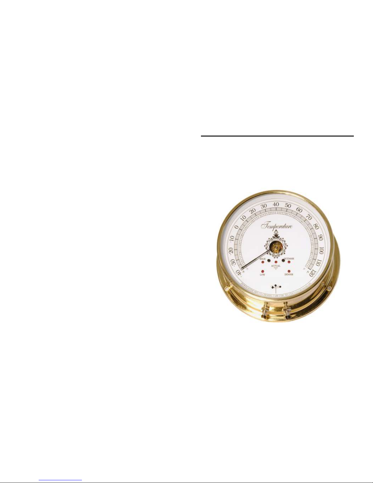
The RIGHT push button (as viewed from the front) switches from
Indoor to Outdoor readings. The LEFT push button switches
between High, Low, and Actual (i.e., current) temperature readings.
To read the current Outdoor temperature, push the Right button
momentarily until the light marked “Outdoor” is lit. Then push the
Left button momentarily until the light marked “Actual” is lit. The
pointer will now indicate the current outdoor temperature. Push
the Left button again to read the Outdoor/Low, then push the Left
button again to read the Outdoor/High. One more push will return
to the current reading.
For Indoor readings, push the Right button once to activate the
“Indoor” light. Then repeat the procedures above to cycle between
High, Low, and Actual (current) readings.
To clear either the High or Low memory, cycle to the indication you
wish to reset and hold the Left button in for 4-5 seconds until the
red light blinks, indicating that the memory has been cleared.
BOX CONTENTS:
1 - Temperature Dial
1 - Temperature sensor and housing with 50' of wire
1 - 6Volt AC power supply plug
Please call with any questions regarding installation or
operation of this instrument.
 Loading...