

Dowco ALUMACRAFT BOAT COVERS WITH COVER-LIFT SYSTEM Installation Instructions Manual
ALUMACRAFT BOAT COVERS WITH COVER-LIFT SYSTEM
INSTALLATION INSTRUCTIONS — CARE & USE GUIDELINES
Please carefully read the entire instructions before proceeding. To emphasize special information you may see these symbols and words:
WARNING
Indicates potential hazard
that could result in death
or injury
Pay special attention to these messages. It is very important to us that you read and understand these installation instructions. If while
reading these instructions you are unsure about installing the cover, please feel free to contact the dealer where you purchased your boat.
Improper installation as a result of not following these instructions may result in damage to the canvas that is not covered by the warranty.
CAUTION
Indicates potential
hazard that could
result in boat damage
NOTE
Indicates special information
to make maintenance easier
or instructions clearer
INSTALLATION:
NOTE: TOOLS REQUIRED
If you need to install mounting hardware you will need a tape measure, a grease pencil/crayon/pen, #2 and #3 Philips
screwdriver bit, ⁄" drill bit, " drill bit, ⁄" drill bit, center punch, power drill, hammer, safety glasses
WARNING
Be sure to use all required safety equipment when using tools and installing hardware
CONGRATULATIONS, YOU HAVE PURCHASED THE LATEST INNOVATION IN BOAT COVERS!
This cover uses a new way to fasten to your boat. It has a support system that uses no poles. You don’t need to crawl under the cover to
prop up the poles. Instead a unique rope-ratchet & strap support system is securely sewn into the underside of the cover. Once the cover is
installed on the boat you simply pull on the rope ratchet to create tension with the straps underneath. The straps rise up slightly creating the
tented effect so that water or rain will run off the cover.
Your boat dealer or the factory may have pre-installed the mounting hardware for the cover — if yes, skip to STEP 7 for cover deployment
instructions. If this has not been done please follow the installation instructions. Locate the mounting hardware and make sure you have all
of the parts indicated.
STEP 1: INSTALLING SPECIAL HARDWARE FOR YOUR COVER
If the female snaps are not installed into the cover you must install them
CAUTION
Make sure there are no wires, fuel lines,
or hoses behind the areas you are drilling
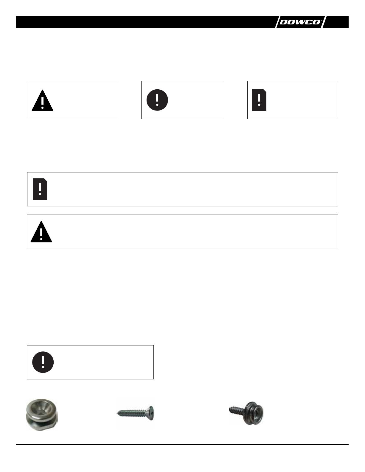
MOUNTING HARDWARE
Mounting Buttons
Quantity: 3
using a snap setting tool. Snaps must be installed about ½” from the edge of
cover through the black webbing. Do not install snaps through the cover without
going through webbing. Location of snaps will be marked with white lines on back
side of cover.
Snap Studs
Mounting Button Screws
Quantity: 3
” when mounting into metal
” when mounting on carpet
Quantity: 8-14 (depending on model)
142674-00 | 06/171
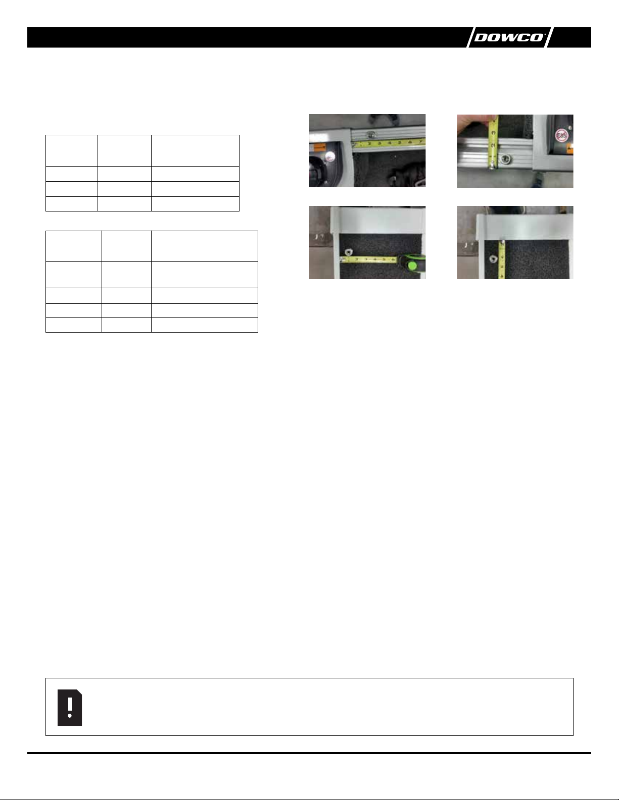
STEP 2
Using a tape measure, locate & mark where each mounting button will be installed for the particular boat model you own (see Fig. 1 for
Gunnel mount). All measurements are to the center on the buttons and studs.
(FIG. 1)
SIDE DECK BOATS
Boat
model
Trophy
T-Pro
Edge
GUNNEL BOATS
Boat
model
Competitor
175 / 185 / 205
Competitor 165
Voyageur
Classic
Dimension
from a cap
2"
2"
2"
Dimension
from a cap
2"
2"
2"
2"
Dimension from inboard
edge of inboard trim
1"
1"
1"
Dimension from outboard side
of gunnel (second grove)
1"
¾"
¾"
¾"
A Button Gunnel A
A Button Side Deck A
A Button Gunnel B
A Button Side Deck B
STEP 3
Inspect the area underneath the gunnel to be sure obstructions or wiring is out of the way. Drill a pilot hole at the proper mounting button
location with a ⁄" drill bit. Install the a mounting button using the mounting button screw in the area described above by inserting the
screw through the center of the mounting button and secure with a #3 Philips bit (see photos above). Repeat this step for the other a
corner mounting location.
STEP 4
Install a mounting button onto the bow plate. Using a tape measure locate the center on the a edge of the bow plate. Measure 1 ½" from
the a edge of the bow plate for the mounting button location. You have to install the mounting button 1 ½” to the right of bow navigation
light socket. Inspect the area underneath the bow plate to be sure obstructions or wiring is out of the way. Drill a pilot hole at the proper bow
mounting button location with a ⁄" drill bit. Insert the screw through the center of the mounting button and secure with #3 Philips bit (see
Fig. 9).
STEP 5 - INSTALLING BOW PLATE SNAPS
Deploy cover as detailed in steps 7–12. Be sure the cover is centered and taut. Mount " bow snap studs 1 ½" forward of a edge of bow
plate and align with female snaps on the cover. Repeat for remaining female bow snap locations. Fasten the bow snaps of the cover to the
studs just installed. Note, you may need to loosen the side ratchets and remove a corners to snap bow snaps.
STEP 6 - INSTALLING MOTOR WELL SKIRT SNAPS
Deploy cover as detailed in steps 7–13. Mount a motor well snap studs. For studs into metal, use a 7/64” drill bit for pilot holes and use 3/8”
snap studs. For studs into carpet use 5/8” snap studs. The drop skirt may vary by boat model. Start with a snap closest to the center of the
boat and work out alternating from port to starboard. Pull down slightly on the skirt so the bottom edge is straight across the motor well. A
snap studs should align with female snaps on the cover. Then install remaining snaps so the skirt’s bottom edge is straight across the motor
well (see Fig. 11).
NOTE
Ensure cover fits properly and tight, indicating all mounting locations line up with cover. At this point, cover can be removed
and packed away.
142674-00 | 06/172
 Loading...