

Page 1
I N S T A L L A T I O N I N F O R M A T I O N
United States
C O M M E R C I A L
Protected Membrane Roof
Installation Guidelines
P M R F I R S T . . . T O L A S T .
Page 2

Table of Contents
O V E R V I E W . . . . . . . . . . . . . . . . . . . . . . . . . . . . . . . . . . . . . . . . . . . . . . . . . . . . . . . . . . . . . . . . . . . 2
G L O S S A R Y . . . . . . . . . . . . . . . . . . . . . . . . . . . . . . . . . . . . . . . . . . . . . . . . . . . . . . . . . . . . . . . . . . . 4
C O M P O N E N T S . . . . . . . . . . . . . . . . . . . . . . . . . . . . . . . . . . . . . . . . . . . . . . . . . . . . . . . . . . . . . 6
STYROFOAM™Extruded Polystyrene Insulation . . . . . . . . . . . . . . . . . . . . . . . . . . . . . . . . . . . . . . 6
Fabric . . . . . . . . . . . . . . . . . . . . . . . . . . . . . . . . . . . . . . . . . . . . . . . . . . . . . . . . . . . . . . . . . . . . . . . 8
Ballast . . . . . . . . . . . . . . . . . . . . . . . . . . . . . . . . . . . . . . . . . . . . . . . . . . . . . . . . . . . . . . . . . . . . . . 10
Pavers . . . . . . . . . . . . . . . . . . . . . . . . . . . . . . . . . . . . . . . . . . . . . . . . . . . . . . . . . . . . . . . . . . . . . . 12
All Other Components . . . . . . . . . . . . . . . . . . . . . . . . . . . . . . . . . . . . . . . . . . . . . . . . . . . . . . . . . 13
C O N D I T I O N S , I S S U E S A N D R A T I N G S . . . . . . . . . . . . . . . . . . . . . . . . 15
Special Conditions and Issues . . . . . . . . . . . . . . . . . . . . . . . . . . . . . . . . . . . . . . . . . . . . . . . . . . . 15
Cold Rain Phenomenon . . . . . . . . . . . . . . . . . . . . . . . . . . . . . . . . . . . . . . . . . . . . . . . . . 15
Moisture Absorption . . . . . . . . . . . . . . . . . . . . . . . . . . . . . . . . . . . . . . . . . . . . . . . . . . . . 16
Dimensional Stability . . . . . . . . . . . . . . . . . . . . . . . . . . . . . . . . . . . . . . . . . . . . . . . . . . . 16
Green Roof Design . . . . . . . . . . . . . . . . . . . . . . . . . . . . . . . . . . . . . . . . . . . . . . . . . . . . . . 17
Finding Leaks in a PMR . . . . . . . . . . . . . . . . . . . . . . . . . . . . . . . . . . . . . . . . . . . . . . . . . . 18
Low Temperature Applications . . . . . . . . . . . . . . . . . . . . . . . . . . . . . . . . . . . . . . . . . . . . 18
High Temperature Installation . . . . . . . . . . . . . . . . . . . . . . . . . . . . . . . . . . . . . . . . . . . . 18
Membrane Seam Failure . . . . . . . . . . . . . . . . . . . . . . . . . . . . . . . . . . . . . . . . . . . . . . . . . 19
Plant Growth on PMR Assemblies . . . . . . . . . . . . . . . . . . . . . . . . . . . . . . . . . . . . . . . . . . 19
T A B L E O F C O N T E N T S
Fire and Wind Ratings . . . . . . . . . . . . . . . . . . . . . . . . . . . . . . . . . . . . . . . . . . . . . . . . . . . . . . . . . 20
Overview . . . . . . . . . . . . . . . . . . . . . . . . . . . . . . . . . . . . . . . . . . . . . . . . . . . . . . . . . . . . . 20
Test Methods . . . . . . . . . . . . . . . . . . . . . . . . . . . . . . . . . . . . . . . . . . . . . . . . . . . . . . . . . . 20
ULI Hourly Fire Resistance Ratings for PMR – Steel Deck . . . . . . . . . . . . . . . . . . . . . . . 21
ULI Hourly Fire Resistance Ratings for PMR – Concrete Deck . . . . . . . . . . . . . . . . . . . . 22
ULI Hourly Fire Resistance Ratings for PMR – Other . . . . . . . . . . . . . . . . . . . . . . . . . . . 22
ULC Hourly Fire Resistance Ratings for PMR – Metal Deck . . . . . . . . . . . . . . . . . . . . . . 23
ULC Hourly Fire Resistance Ratings for PMR – Concrete Deck . . . . . . . . . . . . . . . . . . 24
FM Hourly Fire Resistance Ratings for PMR . . . . . . . . . . . . . . . . . . . . . . . . . . . . . . . . . . 24
FM Class 1 Fire and Wind Uplift . . . . . . . . . . . . . . . . . . . . . . . . . . . . . . . . . . . . . . . . . . . 24
®™Trademark of The Dow Chemical Company (“Dow”) or an affiliated company of Dow
1
Page 3
Overview
C H A N G I N G T H E S E Q U E N C E
Protected membrane roofing’s
breakthrough contribution to
O V E R V I E W
flat roof technology was the
incorporation of an “upsidedown” approach to insulating
the roof: placing the insulation
on top of the waterproof membrane to improve the membrane’s
effectiveness and the insulation’s
efficiency.
This advancement was made
possible in large part by the use
of STYROFOAM™extruded polystyrene insulation, whose
closed-cell, water-resistant qualities have proven to be a key
component in protected membrane roof (PMR) systems.
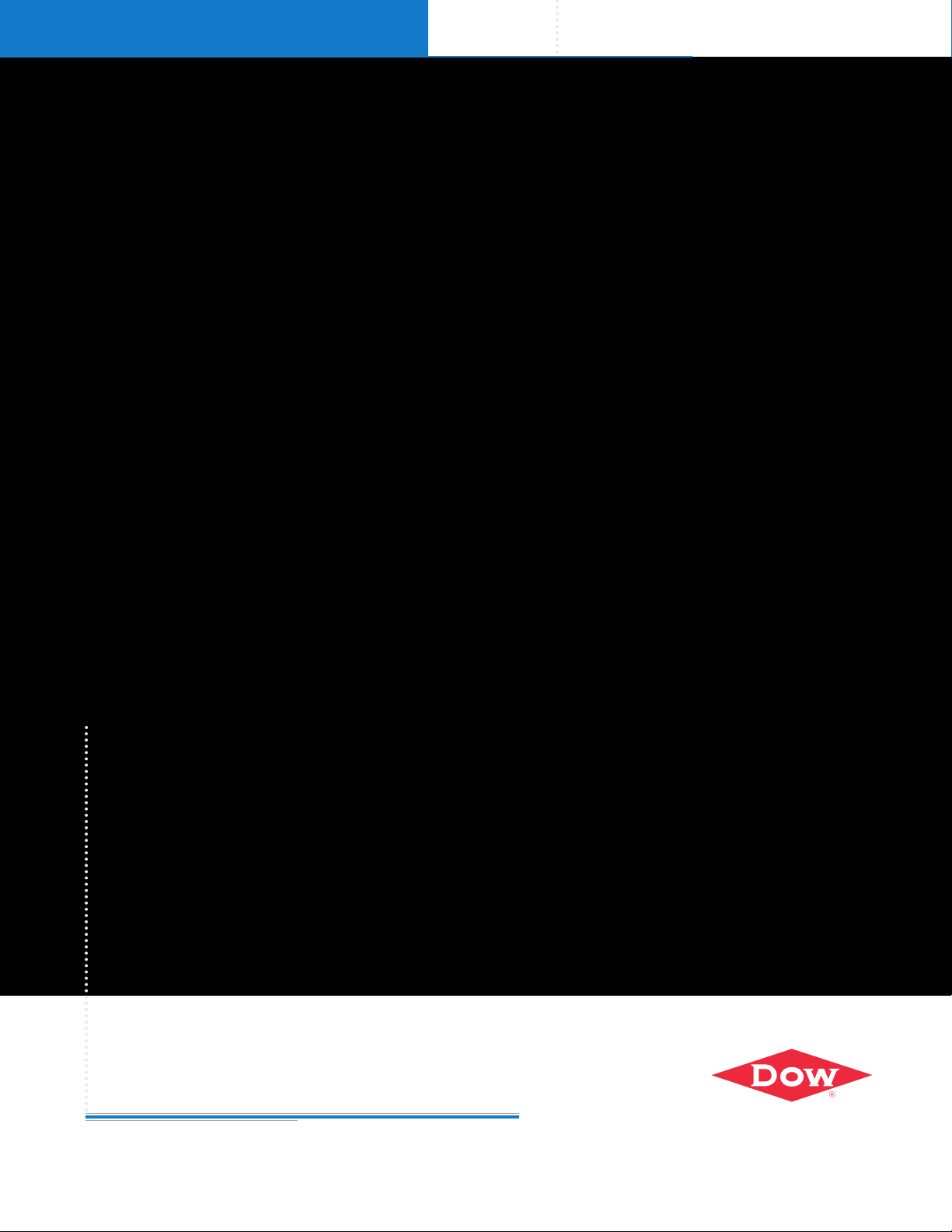
A conventional roof places
the membrane on top of the
insulation, leaving the membrane vulnerable to extreme
temperature changes, freezethaw conditions and physical
abuse from heavy foot traffic
(Figure 1).
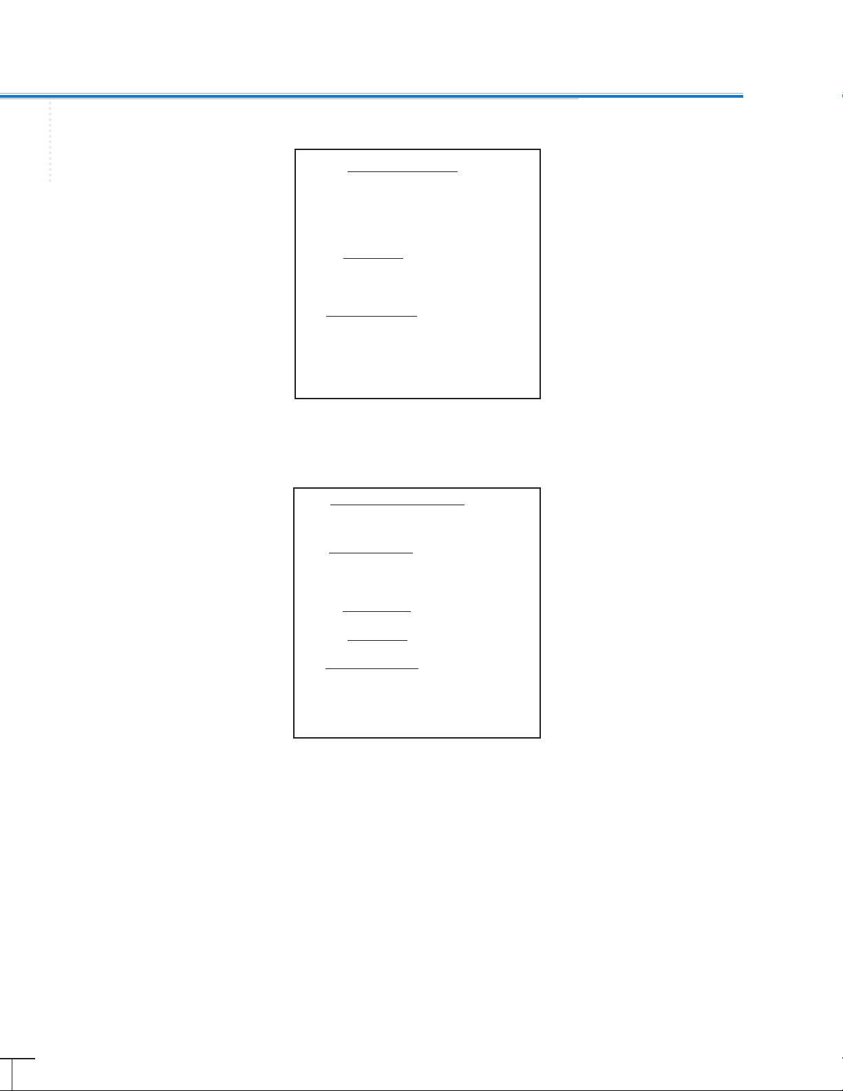
The PMR system places the
insulation on top of the membrane, protecting the roofing
membrane from extreme temperature changes and physical
abuse (Figure 2).
The main difference between
PMR and conventional roofing
is the sequence in which the
materials are applied. The key
to the PMR system is that the
insulation is placed on top of
the waterproofing membrane.
This configuration protects the
membrane, resulting in superior
long-term performance and
durability.
Membrane
STYROFOAM™
Extruded
Polystyrene
Insulation
Deck
Figure 1: Conventional Roof With Membrane Above
the Insulation (depending upon building and climate
conditions, a vapor barrier may also be used)
Ballast
Filter
Fabric
STYROFOAM™
Extruded
Polystyrene
Insulation
Membrane
Deck
Figure 2: PMR With Membrane Below the Insulation
2
®™Trademark of The Dow Chemical Company (“Dow”) or an affiliated company of Dow
Page 4

Overview
C H A N G I N G T H E S E Q U E N C E
Advantages of PMR
All flat roof assemblies consist
of the same basic elements
assembled in a seemingly logical
order: a deck (composed of wood,
metal or concrete), covered with
insulation and topped with a
waterproofing membrane. A
protected membrane roof can
employ the same elements, but
the membrane is positioned
under the insulation, offering
superior long-term performance
and durability.
PMR assemblies:
• Maintain the membrane at a
nearly constant temperature,
close to the temperature of
the building’s interior; this
minimizes the stresses on the
membrane by reducing the
harmful effects of freeze-thaw
cycling, thermal cycling and
excessive heat
• Protect the membrane from
weathering, foot traffic and other
types of physical abuse – both
during and after construction
• Allow year-round construction
since the roof is waterproofed
first, then insulated
• Permit easy removal and re-
installation of the ballast and
insulation for making repairs
or for constructing additional
stories. In addition, a protected
membrane roof provides an
environmentally preferred
option to reuse the insulation
• Allow for a range of ballast
options – stone, precast paving
slabs, green roof, interlocking
stone or concrete – depending
on use and aesthetic
considerations
• Are compatible with a range
of membrane types
• Eliminate the need for a sepa-
rate vapor retarder
PROVIDE DURABILITY
AND PROTECTION
With the membrane positioned
under the insulation, the choice
of insulation becomes an important consideration. The insulation
must be able to withstand wet
environments (without sacrificing
insulation performance) and
foot traffic during and after
construction, while continuing
to perform over time.
Because of its durability and
outstanding moisture-resistant
qualities, STYROFOAM™extruded
polystyrene insulation delivers
exceptional performance in
roofing and plaza applications.
• Provides excellent moisture
resistance and long-term
R-value*
• Offers exceptional durability
to extend the life of the plaza
or roof
• Protects the membrane against
weathering, physical abuse
and damage
• Maintains the membrane at a
relatively constant temperature
• Controls dew point location
O V E R V I E W
®™Trademark of The Dow Chemical Company (“Dow”) or an affiliated company of Dow
*R means resistance to heat flow. The higher the R-value, the greater the insulating power.
3
Page 5

Glossary
Absorption: the ability of a
material to absorb quantities of
G L O S S A R Y
gases or liquids, such as moisture.
Accelerated Weathering: an
experimental test where a material
is exposed in a controlled
environment to various elements
(heat, water, condensation or
light) to magnify the effects
of weathering. The material’s
physical properties are measured
before and after the process to
identify any detrimental effects
of weathering.
Aggregate: rock, stone, crushed
stone, crushed slag or waterworn gravel used for ballasting
a roof system.
Aging: the effect on materials
exposed to an environment for
a defined time.
Alligatoring: the cracking of the
exposed bitumen on a built-up
roof, producing a pattern of cracks
similar to an alligator’s hide.
Asphalt: a dark brown or black
substance left as a residue when
processing crude oil or petroleum.
Asphalt may be further refined
to conform to various roofing
grade specifications.
Asphalt Emulsion: a mixture of
asphalt particles and an emulsifying agent, such as bentonite
clay and water.
Ballast: an anchoring material,
such as stone or precast
concrete pavers, used to hold
insulation and/or roof membranes in place.
Base Ply: the bottom ply of
roofing in a roof membrane or
roof system.
Base Sheet: an impregnated,
saturated or coated felt placed as
the first ply in some multi-ply
built-up and modified bitumen
roof membranes.
Blocking: sections of wood built
into a roof assembly, usually
attached above the deck and
below the membrane or flashing,
used to stiffen the deck around
an opening, act as a stop for
insulation, support a curb or to
serve as a nailer for attachment
of the membrane and/or flashing.
Built-up Roof (BUR) Membrane:
a continuous, semi-flexible multiply roof membrane, made up of
plies or layers of saturated felts,
fabrics or mats with bitumen in
between.
Cant Strip: a beveled or triangular-
shaped strip of wood or other
suitable material used to transition from the horizontal surface
of a roof deck or rigid insulation
to a vertical surface.
Caulking: sealing and making
weather-tight the joints, seams
or voids between adjacent units
using a sealant.
Compatible Materials: two
or more substances that can
be mixed, blended or attached
without separating, reacting or
affecting the materials adversely.
Condensation: the conversion
of water vapor or other gas to
liquid state as the temperature
drops or atmospheric pressure
rises. (Also see Dew Point.)
Counterflashing: formed metal
sheeting secured on or into
another surface used to protect
the upper edge of the membrane
or underlying metal flashing
and associated fasteners from
exposure to the weather.
Dead Load: permanent non-
moving load that results from the
weight of a building’s structural
and architectural components,
mechanical and electrical
equipment, and the roof
assembly itself.
Deck: a structural component of
the roof of a building designed
to safely support the design dead
and live loads, including the
weight of the roof systems, and
the additional live loads required
by the governing building codes.
Decks are either non-combustible
(e.g., corrugated metal, concrete
or gypsum) or combustible (e.g.,
wood plank or plywood) and are
the substrate used to apply the
roofing or waterproofing system.
Design Load: load specified
in building codes or standards
published by federal, state,
county or city agencies, or in
owners’ specifications to be
used in the design of a building.
Dew Point: the temperature
where water vapor condenses
in cooling air at the existing
atmospheric pressure and
vapor content. Cooling at or
below the dew point will cause
condensation.
Dynamic Load: any load that is
non-static, such as a wind load
or a moving live load.
Curb: a raised roof location
relatively low in height.
4
®™Trademark of The Dow Chemical Company (“Dow”) or an affiliated company of Dow
Page 6

Glossary
Fabric: a woven cloth or material
of organic or inorganic filaments,
threads or yarns. Can be used
as a reinforcement in certain
membranes and flashings or
used in a protected membrane
roof application to reduce the
ballast requirements.
Flashing: materials used to
weatherproof or seal the roof
system edges at perimeters,
penetrations, walls, expansion
joints, valleys, drains and other
places where the roof covering
is interrupted or terminated.
Gravel Stop: a low profile,
upward-projecting metal edge
flashing with a flange along the
roof side, usually formed from
sheet or extruded metal. Installed
along the perimeter of a roof to
provide a continuous finished
edge for roofing material.
Humidity: the amount of
moisture contained in the
atmosphere. Generally expressed
as percent relative humidity
(% RH). It is the ratio of the
amount of water vapor actually
present in the air, compared to
the maximum amount that the
air could contain at the same
temperature.
Inverted Roof Membrane
Assembly (IRMA): same as
protected membrane roof (PMR)
assembly, where a closed-cell
insulation (e.g., STYROFOAM
insulation) and ballast are placed
over the roof membrane.
™
Live Load: temporary load
that the roof structure must be
designed to support, as required
by governing building codes.
Can include people, installation
equipment, vehicles, wind,
snow, ice or rain, etc.
Loose-laid Membrane: mem-
brane that is not attached to the
substrate except at the perimeter
of the roof and at penetrations.
Typically, a loose-laid membrane
is held in place with ballast.
Mechanically Fastened
Membrane: membrane that is
attached at defined intervals to
the substrate, using various fasteners and/or other mechanical
devices.
Membrane: a flexible or
semi-flexible material that waterproofs (excludes water) a roof.
Parapet Wall: that part of a
perimeter wall immediately
adjacent to the roof, which
extends above the roof.
PMR: protected membrane roof.
Positive Drainage: the drainage
profile of a deck, considering
the roof slope and loading
deflections to ensure the roof
deck drains within 48 hours of
rainfall during ambient drying
conditions.
Ridge: highest point on the roof
where two roof areas intersect.
Roof Assembly: an assembly
of interacting roof components
(includes the roof deck, vapor
retarder [if present], insulation
and roof covering).
Roof Slope: the angle a roof
surface makes with the horizontal. Typically expressed as a ratio
of rise to run, such as 4:12, or as
a percent.
Square: 100 square feet of roof
area.
Substrate: the surface on which
the roofing or waterproofing
membrane is applied (e.g., the
structural deck or insulation).
Vapor Retarder: a material that
restricts the movement of water
vapor.
Wind Uplift: the force caused by
the deflection of wind at roof
edges, roof peaks or obstructions,
causing a drop in air pressure
immediately above the roof
surface (e.g., suction). Uplift may
also occur from air movement
from underneath the roof deck,
causing the membrane to balloon
and pull away from the deck.
G L O S S A R Y
®™Trademark of The Dow Chemical Company (“Dow”) or an affiliated company of Dow
5
Page 7
Components
S T Y R O F O A M
™
E X T R U D E D P O L Y S T Y R E N E I N S U L A T I O N
Description
STYROFOAM™extruded
polystyrene insulation is a rigid,
closed-cell insulation, ideally
suited and designed for PMR
installations. Because of the
properties imparted during the
extrusion process combined
with the hydrophobic nature
of polystyrene, STYROFOAM
insulation has a high resistance
to both water and water vapor,
providing demonstrated longterm mechanical and thermal
performance.
The boards are available in a
range of thicknesses, densities,
and edge and surface treatments.
STYROFOAM
™
ROOFMATE
An extruded polystyrene foam insulation
providing excellent moisture resistance,
durability and long-term R-value. Ideal
for installation above waterproofing or
roofing membranes in PMR applications.
™
STYROFOAM™Ribbed ROOFMATE
An extruded polystyrene foam insulation
board with 1/4" x 1/2" drainage channels
on the bottom long edge of each board.
The top surface of the board has ribs that
form corrugations in the long dimension
of the board.
Designed for installation above waterproofing or roofing membranes in PMR
applications that use pavers as ballast.
Pavers can be installed directly over the
ribbed foam surface without needing
pedestals.
™
STYROFOAM™PLAZAMATE
A high-density extruded polystyrene foam
C O M P O N E N T S – S T Y R O F O A M E x t r u d e d P o l y s t y r e n e I n s u l a t i o n
insulation board designed to be installed
above waterproofing or roofing membranes
in most plaza deck applications.
™
STYROFOAM™Highload 40, 60 and 100
An extruded polystyrene foam insulation
board with high compressive strength
developed specifically for in-ground
application and freezer floors. The products are also well-suited for plaza decks
and protected membrane roofs that must
withstand heavy traffic.
6
®™Trademark of The Dow Chemical Company (“Dow”) or an affiliated company of Dow
Page 8

Components
S T Y R O F O A M
™
E X T R U D E D P O L Y S T Y R E N E I N S U L A T I O N
Function
Provide thermal properties:
STYROFOAM™extruded polystyrene insulation has a high
aged thermal resistance (R-value)
when compared with competitive roof insulations.
Provide membrane protection:
By installing the insulation over
the membrane, the membrane
is kept at a relatively constant
temperature year-round and
protected from weathering,
mechanical damage and abuse.
Specification
The insulation shall meet
ASTM C578-05 (Type V, VI or
VII depending on the required
properties) or CAN/ULC S701
Type 4.
Install required thickness of
STYROFOAM™extruded polystyrene insulation unbonded
over the roof membrane. Install
a slip or separation sheet over
the membrane if the membrane
is coal tar or Type 1 or 2 asphalt,
or if required by the membrane
manufacturer.
Butt boards tightly together
with a maximum 3/8" gap
between boards, staggering end
joints. The recommended stagger
between each board is 2'.
However, in cases where boards
have been cut to fit, try and
maximize the stagger where possible. At a minimum, each board
should have at least an 8" stagger.
When using STYROFOAM
insulation with pre-cut drainage
channels, ensure that the
drainage channel edges are face
down (i.e., on the membrane side).
Bevel edges to fit closely to
cant slopes.
Fit around protrusions and
obstructions with a maximum
3/4" gap to minimize heat loss.
Multi-layer foam installation:
• The bottom layer of insulation
(the layer directly on the
membrane) must be at least
2" thick.
• The bottom layer must be the
thickest or, at minimum, equal
to the top layer (e.g., 3" bottom
and 3" top).
• Lay successive layers of
insulation unbonded or
unadhered.
• Stagger or offset all joints from
those of the underlying layer.
Installation Notes
Protect insulation from physi-
cal damage.
Handle boards carefully to pre-
vent damage during installation.
Always wear protective eyewear and gloves when handling
and cutting insulation.
Always store insulation away
from direct sunlight, particularly
when storing for an extended
time. Cover with a light-colored
opaque tarp for protection from
solar radiation. The surface
degradation caused by ultraviolet
(UV) light will have no measurable
effect on the insulating value
unless the deterioration is
allowed to continue until actual
thickness is lost.
Always check the compatibility
with other products that may
come in direct contact with the
insulation, particularly those
containing solvents. Preventive
care must be taken, such as
allowing the solvents to evaporate, providing a slip sheet or
painting the surface of the insulation with white latex paint.
Always brush off any surface
dust before applying white latex
paint on the insulation.
STYROFOAM™extruded polystyrene insulation is combustible
and may constitute a fire hazard
if improperly used or installed.
The insulation contains a flameretardant additive to inhibit
ignition from small fire sources.
During shipping, storage, installation and use, this material
should not be exposed to open
flames or other ignition sources.
C O M P O N E N T S – S T Y R O F O A M E x t r u d e d P o l y s t y r e n e I n s u l a t i o n
®™Trademark of The Dow Chemical Company (“Dow”) or an affiliated company of Dow
7
Page 9

Components
F A B R I C
Description
Ballast reduction fabric,
commonly known as filter
fabric, is used in PMR installations between the ballast and
insulation. This water-permeable
material must have proven long-
C O M P O N E N T S – F a b r i c
term weather resistance, be strong
enough to withstand traffic
abuse and prevent displacement
of the insulation under flotation
conditions.
Function
• Prevent fines from penetrating
between insulation boards
• Raft the insulation together
to reduce ballast requirements
• Reduce mechanical damage
to insulation
• Allow easy stone removal if
access required to flashings,
insulation and/or membrane
Specification
Apply fabric unbonded and
shingle fashion over the installed
insulation (Figure 3).
Ballast
Filter Fabric
STYROFOAM™
Extruded Polystyrene
Insulation
Membrane
Deck
Figure 3: Fabric Placement**
Overlap all edges a minimum
of 12". If a small piece has to be
used, minimum size should be
8' x 8'.
Slit fabric to fit over any roof
penetrations. Cut around roof
drains and other openings
(Figure 4).
Ballast
Filter Fabric
Deck
Membrane
Drain Body
Figure 4: Drain Detail With Fabric**
®™Trademark of The Dow Chemical Company (“Dow”) or an affiliated company of Dow
8
**This is an illustration of a typical detail. Responsibility for actual design remains that of the designer.
Drain Cap
Exterior Drain Body
STYROFOAM™
Extruded Polystyrene
Insulation
Drain Line With
Insulation Wrap
Page 10

Components
Deck
Membrane
Ballast
Filter Fabric
STYROFOAM™
Flashing
8' 6"
Ballast at 22 lbs/ft2to 4 Feet
in from Parapet for Wind Uplift
Around Entire Perimeter of Roof
Extruded Polystyrene Insulation
F A B R I C
Extend the fabric up the
roof perimeter cants and roof
protrusions by at least 3" above
the top level of the ballast
(typically about a 6" upturn)
and place it loose under the
metal counterflashings (Figure 5).
Fabrics, such as Fabrene V.I.E.,
should meet or exceed the
guidelines listed in Table 1.
†
Figure 5: Parapet Detail With Fabric**
Specification Guid eline s
Criteria Test Method Units Value
Unit Weight ASTM D1910 oz/yd
Notch Tear lb
MD ASTM D2262 7.0 (min)
CD 7.0 (min)
Tensile Grab lbf
MD ASTM D1682 70 (min)
CD 60 (min)
Elongation @ break ASTM D1682 % 15 (min)
UV Resistance Approved for outdoor use
Material Woven polyolefin preferred
2
4.0 (max)
to promote run-off
C O M P O N E N T S – F a b r i c
T A B L E 1
Installation Notes
Store all materials in dry,
protected areas in an upright
position.
Dow experience has shown
that when the STYROFOAM
extruded polystyrene insulation
is exposed to both direct sunlight
and an outdoor air temperature
over 90°F, distortion of the foam
can occur in as little as 30 minutes
when a heavy, dark-colored fabric
is over the insulation. To prevent
this phenomenon during hot
weather, temporarily place white
opaque polyethylene film on the
fabric until the ballast is laid.
®™Trademark of The Dow Chemical Company (“Dow”) or an affiliated company of Dow
**This is an illustration of a typical detail. Responsibility for actual design remains that
of the designer.
†
Fabrene V.I.E. is a registered trademark of PGI - Fabrene Inc.
™
Install the fabric unadhered
directly over the foam insulation.
Wetting the fabric sometimes
helps secure it until the ballast
can be applied.
Supporting
Documentation
TechNote 501a: “Protecting
STYROFOAM Brand Insulation
Below Dark Roofing Membranes
and Fabrics”
9
Page 11

Components
B A L L A S T
Description
Crushed stone or washed,
rounded riverbed rock, ASTM
D448 Gradation #2, 4, 5 or 57
depending on membrane type,
building height, wind zone and
parapet height (Table 2).
Depending on the ballast
C O M P O N E N T S – B a l l a s t
design, the range of ballast is
10 to 15 lb/ft2with additional
ballast around perimeters and
penetrations (15 to 20 lb/ft2). In
some cases, pavers can be used.
See “Pavers” on page 12 for
additional details.
Function
Prevent uplift and prevent
flotation: The amount and
placement of ballast is based on
the following considerations:
• Design wind speed – Refer to
the ANSI/ASCE 7-95 wind
speed map, contact the local
code authority for the design
wind speed for the building
location or refer to TechNote
508: “Ballast Design Guide for
IRMA Roofs”
• Roof height – Use the worst-
case elevation (e.g., from
ground level to the highest
point of the roof)
• Parapet height – Measured
from the top of the ballast to
the top of the parapet, use the
shortest parapet height in any
variation
• Membrane type – Adhered,
loose-laid or mechanically
attached
Areas of extra ballasting:
Extra ballast, required to overcome
high wind loads and restrain
insulation during heavy rainstorms, should be considered in
the following locations:
• Perimeter edge – 8.5' wide
band running along the
perimeter edge of the roof
insulation. As an alternate to
additional ballast, 1 to 4 rows
of concrete pavers may be
installed along the perimeter
edge (see TechNote 508).
• Penetrations through the insulation – 4' wide band around
any roof penetration greater
than 4' in any direction (e.g.,
skylights, equipment pads, etc.).
• Corners – Concrete pavers may
be required with steel strapping and anchors for certain
designs (see TechNote 508).
See “Pavers” on page 12 for
details about concrete pavers.
• Building exposure – Consider
the surrounding terrain and its
potential effect on the overall
wind exposure (e.g., nearby
woods versus shorelines).
• Membrane type – Adhered,
mechanically fastened or fully
ballasted. For additional
details, see “All Other
Components” on page 13.
Prevent wind scouring: The
wind performance of stone ballasted PMRs has been excellent.
Only a few isolated minor scouring problems have occurred,
typically limited to small areas
in a corner. In these few cases,
the ballast has blown inbound
by about 4' and piled up on the
filter fabric, creating additional
weight.
Prevent UV degradation of
the insulation: Most PMR appli-
cations use a filter fabric that
typically incorporates a UV
stabilizer. However, if no fabric
is used, the insulation must be
totally covered by the ballast to
prevent UV degradation. The
quality of the ballast is very
critical in these types of applications. Too small (fines not more
than 10 percent of mix) and
the stones may work into the
insulation joints or be moved
by the wind; too large and the
ballast may not provide adequate
cover to protect from UV light.
Provide a Class A fire-resistant
roof cover: Class A roof covering,
as defined by ULC S107, ULI
790 and ASTM E108. (See “Fire
and Wind Ratings” on page 20
for additional details.) The
requirements for Class A roof
construction cover the performance of roof assemblies and roof
covering materials when
exposed to a fire originating
from sources outside a building.
The stone ballast or pavers
provide the Class A fire rating.
1 0
T A B L E 2
Standard Size s of Coar se Agg regat e (Weight % Finer T han Sieve Open ings)
ASTM D448 Nominal Size 3" 2-1/2" 2" 1-1/2" 1" 3/4" 1/2" 3/8" 3/16"
Gradation Square Openings
2 2-1/2" to 1-1/2" 100% 90-100% 35-70% 0-15% 0-5%
4 1-1/2" to 3/4" 100% 90-100% 20-55% 0-15% 0-5%
5 1" to 1/2" 100% 90-100% 20-55% 0-10% 0-5%
57 1" to No. 4 100% 95-100% 25-60% 0-10%
®™Trademark of The Dow Chemical Company (“Dow”) or an affiliated company of Dow
Page 12

Components
B A L L A S T
Design Approach
Refer to TechNote 508 for the
recommended amount and
placement of ballast. The ballast
design depends on:
• Type of membrane (adhered,
loose-laid or mechanically
attached)
• Building height
• Design wind speed
• Site exposure
• Parapet height
• Gravel stop height
Specification
ASTM D448 Gradation #2, 4, 5
or 57 washed free of fines or
stones.
Spread stone ballast uniformly
over installed insulation to
provide minimum weight or
thickness.
Spread additional ballast
around the roof perimeter for
a width of 8.5' to increase ballast
weight or thickness.
Spread additional ballast
around any penetration for
a width of 4' around any penetration that exceeds 4' in any
direction.
Installation Notes
Make sure that proper provisions have been specified to seal
off openings in the roof deck
and any perimeter blocks. This
will prevent air from getting
below the roofing membrane
and billowing it.
For PMR installations without
a fabric, ensure that the ballast
does not contain too many small
stones (fines not more than 10
percent of mix) as they may
work into the insulation joints or
be moved by the wind.
Conversely, too many large
stones may not provide adequate cover to protect the insulation from UV light where a
fabric is not used.
If ballast has been moved by
wind scour, repair is simple. Just
replace the insulation (if necessary), re-lay the filter fabric and
replace the ballast. A small paver
can be added, if required.
If a gravel stop is required,
the height of the gravel stop at
a building perimeter should be
at least 2" from the top of the
ballast.
Supporting
Documentation
TechNote 508: “Ballast Design
Guide for IRMA Roofs”
National Research Council
of Canada report by Kind and
Wardlaw. Report on PMRs using
a 30' x 30' wind tunnel, with
various ASTM gradation/sizes
of ballast. (See reports NRC LTRLA 269, NRC LTR-LA 234, NRC
No. 15544.)
ANSI/SPRI RP-4 Wind Design
Standard for Ballasted Single-Ply
Roofing Systems (for mechanically
attached and loose-laid PMR)
ASTM D448 Standard
Classification for Sizes of
Aggregate for Road and Bridge
Construction
ANSI/ASCE 7 Minimum
Design Loads for Buildings and
Other Structures (includes Basic
Wind Speed Map)
C O M P O N E N T S – B a l l a s t
®™Trademark of The Dow Chemical Company (“Dow”) or an affiliated company of Dow
1 1
Page 13

Components
P A V E R S
Description
Concrete slab pavers or interlocking pavers can be used to
supplement or replace conventional stone ballast requirements
and create a surface for rooftop
decks, walkways, terraces, gardens
and similar applications.
C O M P O N E N T S – P a v e r s
Note: For structural plaza deck
design, such as for parking decks
and other high-traffic areas, the
design is the responsibility of an
architect and/or structural engineer.
Function
Note: For additional information,
see “Ballast” on page 10.
Narrow roof walkways for
access: Pavers can be placed to
facilitate access to rooftop
equipment.
Prevent wind scouring: In
exposed areas or areas of high
winds, pavers may be required.
In certain conditions, the pavers
should be strapped together
using galvanized or stainless
steel straps, mechanically fastened to each paver.
Perimeter ballast: Additional
ballast is required around the
building perimeter in a PMR
design. Depending on the
design, pavers can be installed
instead of conventional stone
ballast.
Plaza-deck design: For light
traffic requirements, the stone
ballast can be replaced with
concrete pavers completely. In
many cases, the pavers must be
raised from the surface of the
fabric and insulation. See
“Installation Notes” for details.
Specification
PAVERS
Concrete pavers shall be manufactured from minimum 3,000
lb/in2concrete with a minimum
weight of 18 lb/ft2.
When ribbed insulation is not
used and the total area to be
covered by pavers is more than
10 percent and the location has
more than 3,000 heating degreedays, pavers should be raised
from the surface of the fabric
and insulation using spacers
to maintain at least a 3/16"
ventilating air space (“diffusion
open” design). The spacer can be:
• 1" thick insulation cut into
6" square blocks and placed
under the four corners of the
paver (limited to 108 lb/in
live loading)
• Preformed pavers with at least
a 3/16" foot in each corner or
ribbed undersurface
• Paver pedestal of injection
molded, weathering-grade plastic,
installed under each corner
(e.g., PAVE-EL by Envirospec Inc.,
Terra-Tabs by Wausau Tile, etc.)
• Layer of pea gravel 1" (min.)
free of fines
Note: This air space is not required
if the pavers are covering only a
limited area (less than 10 percent
of roof area), such as corners or
narrow roof walkways.
PAVER STRAPPING AND
FASTENERS (IF REQUIRED):
Straps shall be of 22 gauge
galvanized or stainless steel,
3" wide and 12' long.
Fasteners shall be 1/4" x 1-1/4"
corrosion-resistant metal
anchors, expanded in pre-drilled
holes (e.g., Zamac Nailin #2814
by Powers Fasteners, Inc).
2
Installation Notes
When pavers cover more than
10 percent of the insulation surface and are located in climates
with more than 3,000 heating
degree-days, create a 3/16" space
between the insulation and
the underside of the pavers.
In colder climates, the air space
will minimize any freeze-thaw
spalling on the concrete and
moisture build-up in the insulation due to vapor drive from the
inside.
1 2
®™Trademark of The Dow Chemical Company (“Dow”) or an affiliated company of Dow
Page 14

Components
A L L O T H E R C O M P O N E N T S
Description
MEMBRANES
The membrane is the flexible
or semi-flexible waterproofing
layer on the roof deck. In a PMR
application, the membrane is
sandwiched between the roof
deck and the insulation.
Membranes fall into three
general categories: built-up roof
(BUR), two-ply modified bitumen,
single-ply (sheet) or liquid
membranes.
Note: PMR assemblies should be
installed with adhered membranes
only.
BUR membranes are semi-flex-
ible, multi-ply roof membranes,
consisting of plies or layers of
saturated felts, coated felts, fabrics or mats between alternate
layers of bitumen, either asphalt
or coal tar based.
Modified bitumen membranes
are similar to BUR membranes,
but instead are manufactured in
a production facility, using
asphalt modified with various
additives. The membrane is fully
adhered and the seams overlap
to provide an uninterrupted
waterproof layer.
Sheet or single-ply membranes
are prefabricated sheets of polymerbased material, such as thermoplastic (e.g., PVC), elastomeric
(e.g., EPDM) or modified bitumen
with polymer modifiers. Singleply roofs can be:
• Fully or partially adhered: The
membrane is fully or partially
adhered to the underlying sub-
strate with a flood coat.
• Loose-laid: The membrane is
not attached to the substrate
except at the perimeter and at
penetrations. In a PMR assem-
bly, the loose-laid membrane
is held in place with full ballast.
(See “Ballast” on page 10 for
details.) Care must be taken to
ensure that air infiltration
underneath the membrane is
prevented.
• Mechanically fastened: The
membrane is attached at
defined intervals to the substrate. Mechanical fastening
may use various fasteners and/
or other mechanical devices,
such as plates or battens.
• Self-adhering: The membrane is
adhered to a substrate and to
itself at overlaps without the
use of an additional adhesive.
This is usually accomplished
with a surface adhesive protected by a release paper or
film that prevents the membrane from bonding to itself
during shipping and handling.
Note: With some membranes,
manufacturers may recommend a
slip sheet (e.g., 4-mil polyethylene
film) over the membrane to prevent
adhesion of the foam to the
membrane or plasticizer migration
(e.g., chemical attack) to the
STYROFOAM
styrene insulation. Consult the
membrane manufacturer for
recommendations.
™
extruded poly-
Liquid membranes are applied
in-situ as a liquid that hardens or
sets into a continuous, monolithic
membrane over the substrate.
These liquids are generally
applied by spraying or with
rollers and include:
• Hot-applied rubberized
asphalts, a blend of asphalt,
mineral fillers, elastomers, virgin
or reclaimed oil. Some versions
consist of two coats of rubberized asphalt with a polyester
mat in between (fully reinforced
or two-ply system).
• Cold-applied liquid compounds consist of emulsions
and solutions of resins, elastomers (e.g., polyurethanes,
silicones, acrylics, etc.) and
bitumens and/or modified
bitumens.
FLASHINGS
Flashings are materials used
to weatherproof or seal the roof
system edges at perimeters,
penetrations, walls, expansion
joints, valleys, drains and other
places where the roof covering
is interrupted or terminated. For
example, membrane base flashing covers the edge of the field
membrane, and cap flashings
or counterflashings shield the
upper edges of the base flashing.
ROOF DECK
The roof deck (including
drains and gutters) is the structural component of a building’s
roof. The deck must be capable
of safely supporting the design
dead and live loads, including
the weight of the roof systems
and the additional live loads
required by governing building
codes.
Decks are either non-combustible (e.g., corrugated metal,
concrete or gypsum) or combustible (e.g., wood plank or
plywood), and provide the substrate to which the roofing or
waterproofing system is applied.
C O M P O N E N T S – A l l O t h e r C o m p o n e n t s
®™Trademark of The Dow Chemical Company (“Dow”) or an affiliated company of Dow
1 3
Page 15

Components
A L L O T H E R C O M P O N E N T S
Function
The roof deck should:
• Provide structural support to
accommodate both live and
dead loads without significant
deflection.
• Provide dimensional stability by
forming a stable substrate not
affected adversely by cyclical
thermal- and moisture-induced
movement.
• Provide fire resistance as determined by the building type
and intended use.
• Provide a substrate for the roof
system.
C O M P O N E N T S – A l l O t h e r C o m p o n e n t s
• Accommodate building movement. Where necessary, building
expansion joints and roof area
dividers should be designed
and installed.
• Provide for drainage (either by
sloping the roof deck or using
tapered insulation or both).
The roof surface should be
sound and should drain water
freely within 48 hours following a rain. Every effort should
be made to isolate and correct
the causes of any standing
water or ponding on the roof.
CRCA and NRCA recommend
a minimum slope of 1/4" per
foot (2 percent). The
International Building Code
(IBC) also requires a slope of
1/4", except for coal tar membranes that require 1/8" slope.
However, if the roof is
designed to allow ponding,
ensure the insulation is not
adhered to the membrane
and a filter fabric is used.
• Provide suitable roof drains
and gutters. Care should be
taken to prevent ballast from
entering the drains and/or
gutters by using perforated
collars or paving stones.
When concerns exist, a
drainage assessment should
be conducted per SMACNA
guidelines.
The
membrane should:
• Provide a continuous waterproofing barrier to protect the
interior environment.
• If the membrane is tacky, use
a slip or separation sheet (e.g.,
4-mil polyethylene) to minimize adhesion between the
membrane and insulation.
• If there are compatibility issues
with the membrane, such as
with certain PVC or coal tar
membranes, refer to the
manufacturer’s or supplier’s
recommendations. In some
cases, a slip or separation sheet
(e.g., 4-mil polyethylene) may
be required.
The flashing should:
• Provide a continuous waterproofing barrier when tied
into the membrane to protect
the interior environment.
• Extend well above the expected
high water level (typically 8"
minimum).
Specification
General: The overall system
(including membrane and insulation) should be designed so that
the dew point is located above
the membrane. The system should
be designed so that freezing will
not occur at the membrane level.
Where required, an adequate
thermal barrier should be provided between the insulation and
the interior of the building. The
thermal barrier may consist of the
deck, a ceiling assembly or an
underlayment board equivalent
to 1/2" gypsum board.
Membrane: Refer to membrane
manufacturer’s literature for
details. The manufacturer or
supplier of the membrane shall
be responsible for determining
compatibility of the membrane
with STYROFOAM™extruded
polystyrene insulation.
Roof deck and flashing: Refer
to general roofing specification
for details.
Installation Notes
See the NRCA Roofing and
Waterproofing Manual – Fifth
Edition. Online edition available
at: http://www.nrca.net/rp/
technical/manual/manual.aspx
See the CRCA Roofing
Specification Manual. Details
available at: http://www.roofing
canada.com/ItemsForSale.asp
1 4
®™Trademark of The Dow Chemical Company (“Dow”) or an affiliated company of Dow
Page 16

Conditions, Issues and Ratings
S P E C I A L C O N D I T I O N S A N D I S S U E S
Cold Rain
Phenomenon
THE ISSUE
“Cold rain phenomenon” (or
“cold water wash”) occurs during periods of cold rain and/or
melting snow or when the ambient condition is 33°F to 50°F.
In these conditions, the deck
temperature may be temporarily
reduced. The issue is that there
may be additional heat loss, and
in buildings with high humidity,
such as pulp and paper mills,
the likelihood of condensation
increases.
DISCUSSION
Increased heat loss: Heat loss
studies have shown that extra
heat loss in PMR systems during
periods of “cold rain” is a temporary phenomenon, occurring
only during the short time of
cold rain in a heating season. In
fact, cold rain in the cooling
season creates a cooling advantage for a PMR system. Studies
comparing a conventional versus
PMR assembly show only a 3
percent overall heat loss disadvantage for the PMR assembly.
High temperature/high humidity
buildings: According to NRCA, a
building with 45 percent RH is
considered high moisture occupancy. Other buildings, such as
pulp and paper mills, textile
mills and natatoriums, can have
an even higher internal humidity.
Combining high humidity with
a higher than normal operating
temperature results in a “high
temperature/high humidity”
building environment that
requires special design
consideration.
The severe operating conditions
of high temperature/high humidity
buildings are particularly problematic for conventional roof
systems. The high temperatures
drive the high humidity up
into the roof system, resulting
in severe condensation and
premature deterioration of the
insulation and roof deck.
A PMR system offers an inherent design solution for this
moisture problem. The waterproof roof membrane is an
excellent vapor retarder. With
the membrane directly on the
roof deck and the insulation
above the membrane, the membrane effectively blocks water
vapor from reaching the insulation. Also, the membrane is
maintained at a temperature
near that of the interior, dramatically reducing the probability of
condensation on the membrane
and minimizing the possibility
of premature roof failure.
The “cold rain phenomenon”
can change this situation. Cold
rain, filtering past the insulation
to the membrane, can cool the
membrane and the deck below,
resulting in a temporary condensation condition on the
underside of the deck. For some
businesses, like pulp and paper
mills, this dripping condensation
can create problems with the
manufacturing processes and
products, causing decreased
productivity and increased
production costs.
To solve this problem, a thin
layer of insulation can be placed
below the membrane. This layer
keeps the roof deck warm during
brief cold rain periods – maintaining the inherent advantages
of a PMR system while mitigating the problem of the “cold
rain phenomenon.”
See TechNote 507: “STYROFOAM
Insulation in the Optimum
Design System for Pulp & Paper
Mill Roofs” for additional details.
CONCLUSION
The effect of “cold rain phenomenon” is temporary and
does not have a significant overall effect on the performance of
a PMR assembly. Generally,
thicker amounts of insulation
are not required to counteract
the negative effects of cold rain.
In high humidity and high
temperature applications, sandwiching the membrane between
two layers of insulation, coupled
with a vapor retarder on the
roof deck will address condensation problems in high humidity
roofing systems. Remember that
the thicker insulation layer
should be above the membrane
to ensure the dew point is above
the membrane.
C O N D I T I O N S , I S S U E S A N D R A T I N G S – S p e c i a l C o n d i t i o n s a n d I s s u e s
™
®™Trademark of The Dow Chemical Company (“Dow”) or an affiliated company of Dow
1 5
Page 17

Conditions, Issues and Ratings
S P E C I A L C O N D I T I O N S A N D I S S U E S
Moisture
Absorption
THE ISSUE
STYROFOAM™extruded polystyrene insulation will absorb
water and the insulation value
will be reduced.
DISCUSSION
In a PMR design, it is critical
that any insulation installed
above the membrane can perform in a wet environment
without any detrimental effects
on its long-term performance.
STYROFOAM™extruded polystyrene insulation has a unique
closed-cell structure that provides
excellent moisture resistance
and long-term R-value.
Nine PMR systems were monitored over a period of 22 years
and the insulation properties
assessed. The average moisture
content of the insulation was
0.9 percent on a percent by
volume basis, with a retained
R-value of 96 percent.
In plaza deck designs, it is
important that a drainage layer
C O N D I T I O N S , I S S U E S A N D R A T I N G S – S p e c i a l C o n d i t i o n s a n d I s s u e s
be created above the insulation,
allowing precipitation to drain
off the top surface of the insulation, creating a “diffusion open”
assembly. If the insulation is
sandwiched between a vapor
barrier (e.g., pavers) and the roof
deck, vapor cannot escape so it
is driven back into the insulation. To create a “diffusion
open” layer, ensure impermeable roof coverings (such as
pavers) have a ventilating air
space. This could be a layer of
fine-free gravel or a 3/16" minimum air space. See “Pavers” on
page 12 for additional details. In
addition, if the wearing surface
is installed in direct contact
with the insulation, moisture
may become trapped and freezethaw cycling could cause
spalling on the bottom of the
wearing surface.
Always ensure that the roof
deck has proper drainage; if the
PMR system has significant
ponding (e.g., standing water), the
insulation will not be “diffusion
open.” Follow roofing association
guidelines for drainage recommendations.
CONCLUSION
STYROFOAM™extruded
polystyrene insulation offers
demonstrated long-term performance in a PMR assembly.
Dimensional
Stability
THE ISSUE
STYROFOAM™extruded polystyrene insulation “shrinks”
over time, leading to increased
heat loss.
DISCUSSION
All building materials will
experience dimensional change
due to temperature fluctuations.
STYROFOAM™extruded polystyrene insulation is no different.
For example, the coefficient of
expansion of STYROFOAM
extruded polystyrene insulation
is 3.5 x 10⁻⁵in/in/°F. A 2' x 8'
sheet of insulation exposed to a
temperature swing of 75°F could
result in a maximum change of
just 1/4" in the 8' direction.
Once the temperature is
reduced, the insulation will
return to its original cut dimension.
In addition, this theoretical
change does not account for the
temperature profile across the
insulation. For example, while
one side may see a large temperature swing, the underside may
see only a small change.
This relatively small gap
between the boards does not significantly increase the heat loss
through the board joints. In
heat loss studies comparing PMR
versus conventional roofs, there
was no significant difference
between the two systems. The
findings showed that the PMR
system used 3 percent more
energy per year.
In addition to addressing the
coefficient of expansion, another
consideration is the “creep” of
materials. Creep is the permanent
deformation resulting from
continuous, long-term dead
(or non-moving) loads. Creep
is generally only an issue for
STYROFOAM insulation used in
pavements, airport runways,
parking decks, floors, etc. –
installations where the insulation
is used to carry a significant
load for a long time. In these
applications, higher compressive
strength insulation may be
required.
CONCLUSION
All building materials have a
coefficient of expansion that
results in dimensional change
with temperature fluctuations.
The dimensional change that
occurs in STYROFOAM™insulation in a PMR assembly does not
significantly impact the system’s
thermal performance.
1 6
®™Trademark of The Dow Chemical Company (“Dow”) or an affiliated company of Dow
Page 18

Conditions, Issues and Ratings
S P E C I A L C O N D I T I O N S A N D I S S U E S
Green Roof Design
THE ISSUE
Can PMR assemblies be used
for “green roof” designs?
DISCUSSION
In a “green roof” design, the
ballast in a PMR assembly is
essentially replaced with green
material – usually soil and
plantings – plus a drainage layer
directly on top of the insulation
(Figure 6). Replacing conventional ballast with vegetation can
limit storm water runoff and, by
filtering the runoff through the
plants, also improve the quality
of the runoff. The plantings not
only ballast the insulation, they
can, depending on the configuration, also add additional
R-value to the roof assembly.
Green roofs provide habitat for
insects and other wildlife and
often are considered in buildings
applying for LEED††(Leadership
in Energy & Environmental
Design) certification.
Many materials may be suitable
as ballast, provided they are
compatible with the insulation,
prevent flotation, shield ultraviolet light and provide a Class
A fire-resistant roof finish.
The roof structure must also be
designed to accommodate the
dead load from the additional
weight of the plantings (including
when they are fully saturated by
rainfall and covered in several
feet of snow), plus any live load
from traffic, if applicable. It is
also important to design the
roof slope and drainage system
to accommodate rain runoff.
Vegetation
Soil
System Filters
Filter Fabric
STYROFOAM™
Extruded
Polystyrene
Insulation
Membrane
Deck
Figure 6: Green Roof Design
PMR assemblies are ideal for
green roof designs:
• The membrane is protected
under the insulation.
• Because STYROFOAM™extruded polystyrene products come
in a range of compressive
strengths, the insulation layer
can be designed to withstand
the higher dead loads.
• STYROFOAM insulation is
proven to outperform in a
moist environment.
• STYROFOAM insulation has a
high modulus of elasticity,
allowing it to perform under
long-term live or cycle loading.
Maximum recommended
dynamic (live) load is 1/10 of
the rated compressive strength
for 1,000,000 repetitions to
address creep and fatigue
guidelines.
Typically, a drainage layer is
placed over the insulation to
direct runoff to the drains, as
well as keep the top surface of
the insulation “diffusion open.”
(See “Moisture Absorption” on
page 16 for details.) This
drainage layer usually includes a
fabric over the insulation to protect the joints and keep them
open for drainage. Any stone
used for this drainage layer must
be clean and have a low percentage of fines. In some cases,
a drainage mat combined with a
filter fabric has also been used
successfully to create the necessary air space.
For additional information on
green roof design, see:
Design Guidelines for Green Roofs,
by Steven Peck and Monica
Kuhn, B.E.S., B. Arch., OAA, an
OAA and CMHC publication,
available at http://www.cmhcschl.gc.ca
CONCLUSION
PMR assemblies are ideally
suited to green roof designs.
C O N D I T I O N S , I S S U E S A N D R A T I N G S – S p e c i a l C o n d i t i o n s a n d I s s u e s
®™Trademark of The Dow Chemical Company (“Dow”) or an affiliated company of Dow
††
Trademark of the U.S. Green Building Council
1 7
Page 19

Conditions, Issues and Ratings
S P E C I A L C O N D I T I O N S A N D I S S U E S
Finding Leaks
in a PMR
THE ISSUE
Is it more difficult to locate a
leak with a PMR or conventional
roof assembly?
DISCUSSION
Building upon years of in-field
experience, the majority of roof
leaks in PMR systems occur at
flashing as opposed to the interior field area. The field area is
protected from physical abuse,
UV attack and thermal cycling –
all factors that are the primary
causes of roof failures – by both
the insulation and ballast over
the membrane. However, sometimes interior field leaks do
occur.
Concrete decks: For PMR
installations on concrete decks,
generally the membrane is fully
adhered to the deck. This simplifies leak detection because the
leak is localized. For example,
the leak in the interior will be
exactly where the hole in the
membrane is located. If the
C O N D I T I O N S , I S S U E S A N D R A T I N G S – S p e c i a l C o n d i t i o n s a n d I s s u e s
membrane is not adhered, the
water can run under the membrane for many feet before
entering the building – just like
in a conventional roof.
Steel decks: For PMR installations on steel decks, a layer of
insulation or other substrate
(e.g., drywall) is placed first to
provide a base for the membrane – exactly the same as in a
conventional roof. The same
type of leak detection effort is
required for both PMR and conventional roofs on steel decks.
Wood decks: On wood decks
with a PMR installation, the
membrane is typically a felt
layer and two or three plies
mopped on top. In a conventional installation, the insulation
is fastened to the deck and then
the membrane is applied. Both
of these approaches will allow
the water to run to the deck
joints prior to entering the
building.
CONCLUSION
Not only do PMR assemblies
have fewer leaks in the first
place, PMR assemblies over
concrete decks with bonded
membranes have definite advantages when isolating any leaks
that do occur. Both conventional
and PMR roofs over steel or
wood decks require the same
leak detection strategies. In
addition, because PMR roofs are
easier to repair and typically all
of the original materials can be
reused (ballast and insulation),
this environmentally friendly
feature can save money.
Low Temperature
Applications
THE ISSUE
PMR assemblies should
not be used in low temperature
applications because of the
potential adverse effect on the
STYROFOAM™extruded polystyrene insulation.
DISCUSSION
In a low temperature application (e.g., freezers), the interior
space has a low temperature and
low water vapor pressure
(humidity). In contrast, the
warm outside temperature and
higher water vapor pressure
causes a vapor drive toward the
interior space. Unless addressed,
this vapor can condense in the
insulation and lower the R-value
of the system. It can also condense on the membrane and
freeze, gradually forming a layer
of thick ice.
Typically in low temperature
applications, the membrane is
placed on the “warm side” – or
the exterior in a conventional
roofing application.
CONCLUSION
In low temperature applications
(e.g., freezers), a conventional
roof may offer performance
benefits.
High Temperature
Installation
THE ISSUE
In high temperature locations,
PMR assemblies should not
be covered with a dark fabric
prior to laying the ballast
because of the potential adverse
effect on the STYROFOAM
extruded polystyrene insulation.
DISCUSSION
Like many insulations, higher
temperatures may cause permanent
distortion and/or long-term
creep. The maximum use
temperature for STYROFOAM
extruded polystyrene insulation
is 165°F for continuous use,
with short-term exposure up to
190°F.
Typically, this concern arises
in warmer locations (e.g., southern U.S.) when STYROFOAM
insulation is placed underneath
a dark fabric prior to laying the
ballast. Given the right conditions, the temperature on the
top of the insulation may reach
close to the upper limits for
polystyrene insulation and cause
some distortion. Experience has
shown that when the STYROFOAM
insulation is exposed to both
direct sunlight and an outdoor
air temperature over 90°F, distortion of the foam can occur in as
little as 30 minutes when a
heavy fabric is over the insulation.
To prevent this phenomenon
during hot weather, temporarily
place white opaque polyethylene
film on the fabric until the
ballast is laid.
CONCLUSION
In high temperature locations,
the temporary use of white
opaque polyethylene film laid
on the fabric until the ballast is
laid will prevent any distortion
of the insulation.
™
™
1 8
®™Trademark of The Dow Chemical Company (“Dow”) or an affiliated company of Dow
Page 20

Conditions, Issues and Ratings
S P E C I A L C O N D I T I O N S A N D I S S U E S
Membrane Seam
Failure
THE ISSUE
Failures at the seams in
thermoset membranes may
be worse with PMR because
the membrane stays damp.
DISCUSSION
Thermoset membranes (such
as EPDM and neoprene) were
historically seamed with a contact adhesive. Seam failure due
to moisture intrusion or other
contaminant was a concern for
this type of membrane because
the membrane stays damp in a
PMR, potentially resulting in an
increase in seam failure. In fact,
Dow never received a complaint
about this perceived concern.
In today’s EPDM system, a
seam tape is used. This tape has
exhibited excellent performance
and this is no longer an issue.
CONCLUSION
There are no documented
cases of seam failure related to
the PMR application.
Plant Growth on
PMR Assemblies
THE ISSUE
Periodically, plant growth
will occur on PMR and other
low-sloped roofs. Can this be
avoided?
DISCUSSION
At times, grass, weeds or small
trees may grow on both PMR
and conventional roofs. Good
roofing practice should include
a maintenance program that
includes periodic inspection for
this type of growth. Any plant
growth should be pulled out
and, if required, the area treated
with a weed killer.
Roots from plant growth can
sometimes damage the membrane if left unchecked. With a
PMR system, there is less chance
of this happening since the
membrane is protected by the
insulation, fabric and ballast.
CONCLUSION
A preventive maintenance and
inspection program should
include inspection and removal
of any plant growth.
C O N D I T I O N S , I S S U E S A N D R A T I N G S – S p e c i a l C o n d i t i o n s a n d I s s u e s
®™Trademark of The Dow Chemical Company (“Dow”) or an affiliated company of Dow
1 9
Page 21

Conditions, Issues and Ratings
F I R E A N D W I N D R A T I N G S
Overview
Fire and wind ratings are
required to meet building code
requirements. Typically, a PMR
assembly, including roof deck,
membrane, insulation and
ballast, is tested in exactly the
same configuration as would
be constructed in the field. No
deviation from the component
specification is allowed.
Underwriters Laboratories Inc.
(ULI), Underwriters Laboratories
Canada (ULC) and Factory
Mutual (FM) have developed test
methods to rate the fire and
wind properties of assemblies.
For the most current listings,
contact Dow at 1-866-583-BLUE
(2583).
Test Methods
FIRE RESISTANCE RATINGS –
FIRE WITHIN A BUILDING
Both ULI and ULC test roof
C O N D I T I O N S , I S S U E S A N D R A T I N G S – F i r e a n d W i n d R a t i n g s
assemblies based on the type of
fire exposure. For fires originating
within a building, roof assemblies
are assessed using either ANSI/UL
263 or CAN/ULC S101-M.
When testing for fires originating within a building, a full-scale
roof system is exposed to a
controlled fire in order to assess
a construction/assembly that
can contain a fully developed
fire. The Fire Resistance Rating
represents the time it takes for
the temperature on the unexposed side of the assembly to
increase by 250°F.
A sample measuring approximately 14' x 17' is used,
including the decking material,
any suspended ceiling, hangers,
insulation, etc. The sample is
then exposed to a fire with
temperatures reaching 1,000°F
at five minutes and then 1,700°F
for a specified time. During the
test, a load is applied to the floor
to represent the maximum load
the joists are designed to support.
EXTERNAL FIRE
PERFORMANCE OF
A ROOF ASSEMBLY
The fire resistance performance
of roof coverings exposed to
simulated fire source originating
outside a building is conducted
in accordance with UL 790
(ASTM E108) or CAN/ULC S107-M.
Three classifications are available.
Class A roof covering:
• Effective against severe fire test
exposures
• Provides a high degree of fire
protection
• Not expected to produce flying
embers
• Does not slip from position
during the test
Class B roof covering:
• Effective against moderate fire
test exposures
• Provides a moderate degree of
fire protection
• Not expected to produce flying
embers
• Does not slip from position
during the test
Class C roof covering:
• Effective against light fire test
exposures
• Provides a light degree of fire
protection
• Not expected to produce flying
embers
• Does not slip from position
during the test
Note: PMR assemblies ballasted
with a minimum of 9 lb/ft2of
stone ballast (or pavers installed
with a maximum gap of 1/4")
achieve a Class A rating.
FM TESTS FOR
WIND PERFORMANCE
Factory Mutual approved roof
assemblies are only required when
the building is insured by FM
Global. Building code authorities
may recognize some FM
standards; however, they do not
require the use of FM approved
or accepted products and systems.
FM 4450, “Approval Standard
for Class 1 Insulated Steel Deck
Roofs,” and FM 4470, “Approval
Standard for Class 1 Roof
Covers,” are two recognized
laboratory test methods for
determining the wind-uplift
resistances of roof assemblies.
FM 4450 and FM 4470 are the
basis of FM’s 1-60, 1-90, 1-120,
etc., approvals. For example, a
Class 1-60 design resists a 60
lb/ft2uplift pressure for one
minute without loss of pressure.
Dow has a PMR system rated
FM 1-90 that adheres
STYROFOAM™extruded polystyrene insulation to a BUR roof
assembly with asphalt. This system can be used on both steel
and concrete roof decks. Looselaid single-ply roof membranes
with ballast are not listed in the
FM approval guide since there
are not methods to test these
systems for wind uplift. Looselaid systems can be “accepted”
by FM if the assembly is ballasted in accordance with FM Loss
Prevention Guide 1-29 and
reviewed by the local FM engineering office.
IBC REQUIREMENTS
FOR BALLASTED ROOF
ASSEMBLIES
The International Building
Code (IBC) requires that ballasted roofing assemblies, including
PMR assemblies, be ballasted in
accordance with ANSI/SPRI RP-4.
This standard can be downloaded (free of charge) at
www.spri.org
2 0
®™Trademark of The Dow Chemical Company (“Dow”) or an affiliated company of Dow
Page 22

Conditions, Issues and Ratings
F I R E A N D W I N D R A T I N G S
ULI Hourly Fire
Resistance Ratings for
PMR – Steel Deck
Assembly #
P-225, P-226, P-235
(New PMR)
P-404
(New PMR)
P-801, P-805
(Retrofit PMR)
P-803
(Retrofit PMR)
P-811
(New PMR)
P-813
(New PMR)
Rating (hrs)
1, 1-1/2
1-1/2
1, 1-1/2, 2
1, 1-1/2
1, 1-1/2, 2, 3
1, 1-1/2
Description
Steel deck
1/2" or 5/8" Type X gypsum (varies)
Bar joists
Suspended ceiling
Steel deck
1" mineral or fiberboard
Bar joists
Plaster ceiling
Steel deck
Mineral or fiberboards
Spray fiber fireproofing
Beam construction
Steel deck
Mineral or fiberboards
Spray fiber fireproofing
Bar joists
Steel deck
5/8" Type X gypsum
Spray fiber fireproofing
Beam construction
Suspended ceiling (optional)
Steel deck
5/8" Type X gypsum
Spray fiber fireproofing
Bar joists
C O N D I T I O N S , I S S U E S A N D R A T I N G S – F i r e a n d W i n d R a t i n g s
P-908
2
Steel deck
3-5/6" vermiculite concrete
Beam construction
Note: Always refer to the actual listing for complete details, including
maximum thickness of insulation allowed. For details, call Dow at
1-866-583-BLUE (2583).
®™Trademark of The Dow Chemical Company (“Dow”) or an affiliated company of Dow
2 1
Page 23

Conditions, Issues and Ratings
F I R E A N D W I N D R A T I N G S
ULI Hourly Fire
Resistance Ratings for
PMR – Concrete Deck
Assembly #
P-904, P-909,
P-912, P-915
(Retrofit PMR)
P-904, P-909,
P-912, P-915
(New PMR)
Assembly #
P-229, P-505, P-507
(New PMR)
C O N D I T I O N S , I S S U E S A N D R A T I N G S – F i r e a n d W i n d R a t i n g s
Rating (hrs)
2
2
ULI Hourly Fire
Resistance Ratings for
PMR – Other
Rating (hrs)
1, 1-1/2
Description
Precast concrete units
Mineral fiberboard
Precast concrete units
1" gypsum board
Description
2' poured gypsum deck
Bar joists
Suspended ceiling
2 2
®™Trademark of The Dow Chemical Company (“Dow”) or an affiliated company of Dow
Page 24

Conditions, Issues and Ratings
F I R E A N D W I N D R A T I N G S
ULC Hourly Fire
Resistance Ratings for
PMR – Metal Deck
Assembly #
R-202, R-217
(New PMR)
R-702, R-703
(New PMR)
R-804
(New PMR)
R-805, R-806
(New PMR)
Rating (hrs)
1
1, 1-1/2
3/4, 1, 1-1/2,
2, 3
1
Description
Steel deck
1/2" gypsum
Beams or bar joists
Suspended ceiling
Steel deck
5/8" gypsum
Spray cementitious mixture
Beams or bar joists
Steel deck
5/8" Type X gypsum
Spray fiber fireproofing
Beam construction
Steel deck
1/2" or 5/8" Type X gypsum (varies)
Spray fiber fireproofing
Beams or bar joists
C O N D I T I O N S , I S S U E S A N D R A T I N G S – F i r e a n d W i n d R a t i n g s
®™Trademark of The Dow Chemical Company (“Dow”) or an affiliated company of Dow
2 3
Page 25

Conditions, Issues and Ratings
F I R E A N D W I N D R A T I N G S
ULC Hourly Fire
Resistance Ratings for
PMR – Concrete Deck
Assembly #
P-229, P-505, P-507
(New PMR)
Assembly #
RC-227
(New PMR)
RC-264
(New PMR)
C O N D I T I O N S , I S S U E S A N D R A T I N G S – F i r e a n d W i n d R a t i n g s
Class
1-60, 1-90
Rating (hrs)
1, 1-1/2
FM Hourly Fire Resistance
Ratings for PMR
Rating (hrs)
1
1
FM Class 1 Fire and
Wind Uplift
Description
Steel deck
1/2" StrataGuard
(mechanically fastened)
3-ply BUR
§
or 5/8" DensDeck
Description
2' poured gypsum deck
Bar joists
Suspended ceiling
Description
Steel deck
1/2" Type X gypsum
Gypsum board ceiling
Steel deck
1/2" Type X gypsum
Suspended ceiling
§§
2 4
Note: Current FM wind tests cannot be used to evaluate loose-applied
roofing systems. FM Loss Prevention Guide 1-29 provides accepted
ballasting requirements.
®™Trademark of The Dow Chemical Company (“Dow”) or an affiliated company of Dow
§
StrataGuard is a trademark of Owens Corning
§§
DensDeck is a trademark of Georgia-Pacific
Page 26

IN THE U.S.:
• For Technical Information: 1-866-583-BLUE (2583)
• For Sales Information: 1-800-232-2436
THE DOW CHEMICAL COMPANY
• Building Solutions • 200 Larkin • Midland, MI 48674 • www.dowstyrofoam.com/architect
NOTICE: No freedom from infringement of any patent owned by Dow or others is to be inferred. Because use conditions and applicable laws may differ from one location to another and may change with time, Customer is responsible for determining whether products and the information in this document are appropriate for Customer's use and for ensuring that Customer's workplace and disposal practices are in compliance with applicable laws and other
government enactments. The product shown in this literature may not be available for sale and/or available in all geographies where Dow is represented. The claims made may not have been approved for use in all countries. Dow
assumes no obligation or liability for the information in this document. References to “Dow” or the “Company” mean the Dow legal entity selling the products to Customer unless otherwise expressly noted. NO WARRANTIES ARE
GIVEN; ALL IMPLIED WARRANTIES OF MERCHANTABILITY OR FITNESS FOR A PARTICULAR PURPOSE ARE EXPRESSLY EXCLUDED.
COMBUSTIBLE: Protect from high heat sources. Local building codes may require a protective or thermal barrier. For more information, consult MSDS or call Dow at 1-866-583-BLUE (2583). In an emergency, call 1-989-636-4400.
Building and/or construction practices unrelated to building materials could greatly affect moisture and the potential for mold formation. No material supplier including Dow can give assurance that mold will not develop in any specific
system.
Printed in U.S.A.
®™Trademark of The Dow Chemical Company
(“Dow”) or an affiliated company of Dow
Form No. 179-05051-0713MCK
McKAY219202
 Loading...