

Page 1

FROTHPAK™
REFILL SYSTEMS
MANUAL
INSTALL MANUAL | United States | COMMERCIAL/RESIDENTIAL
2014 EDITION
Manual
Page 2

Table of Contents
FROTHPAK™ Refill System Installation .........................................................A1
Nitrogen Regulator Assembly.................................................................... A2
INSTAFLO™ Gun...............................................................................A3
Anti-crossover Nozzles . . . . . . . . . . . . . . . . . . . . . . . . . . . . . . . . . . . . . . . . . . . . . . . . . . . . . . . . . . . . . . . . . . . . . . . . . . A4
Introduction ................................................................................................... 2
Section 1: System Information
1.1 Ordering Information ..........................................................................3
1.2 Refill Accessories .............................................................................3
1.3 Anti-crossover Nozzles (25 Pack) ..............................................................4
1.4 Shipping Weights..............................................................................4
1.5 Tank Dimensions ..............................................................................4
1.6 Freight Classification for Tank Return ..........................................................5
Section 2: Safety Precautions
2.1 Respiratory Protection.........................................................................6
2.2 Isocyanate-induced Occupational Asthma .....................................................6
2.3 Safety Clothing................................................................................6
2.4 Skin Contact ..................................................................................6
2.5 Eye Contact ...................................................................................6
2.6 Ingestion ......................................................................................7
2.7 Removal of Cured Foam on Skin ...............................................................7
2.8 Overfilling Restricted Spaces ..................................................................7
2.9 Chemical Information ..........................................................................7
2.10 Chemical Spills...............................................................................7
2.10.1 “A” Chemical .........................................................................7
2.10.2 “B” Chemical.........................................................................7
2.11 Cautions .....................................................................................7
2.11.1 Storage Temperature ................................................................7
2.11.2 Building Codes ......................................................................7
2.11.3 Surface Temperature Restrictions ....................................................7
2.11.4 Open Flame/Spark Source...........................................................7
2.11.5 Excessive Foam Dispensing..........................................................7
2.12 Training ......................................................................................7
Section 3: System Installation
3.1 Initial Tank Set-up .............................................................................8
3.2 Tank Positioning...............................................................................9
3.3 Nitrogen Regulator Installation................................................................ 9
3.4 Chemical Hose Installation....................................................................10
Section 4: Start-up Procedure
4.1 System Pressurization ........................................................................10
4.2 Calibration Instructions .......................................................................11
4.3 System Purging and Testing ..................................................................13
4.4 Nozzle Replacement..........................................................................13
Page 3

Section 5: INSTAFLO™ Gun Operation...................................................................13
5.1 Spraying ....................................................................................13
5.2 INSTAFLO
™
Gun Operation .................................................................14
Section 6: Shut-down Procedure ................................................................... 14
Section 7: Storage................................................................................. 15
Section 8: Re-start Procedure ......................................................................15
8.1 System Pressurization .......................................................................15
8.2 System Purging and Testing .................................................................16
Section 9: Tank Change-over....................................................................... 16
9.1 “A” Tank Change-over........................................................................17
9.2 “B” Tank Change-over .......................................................................18
9.3 Tank Return ................................................................................. 18
9.4 System Pressurization .......................................................................19
9.5 System Purging and Testing .................................................................19
Section 10: Troubleshooting......................................................................... 19
10.1 Temperature .............................................................................19
10.2 Foam Color and Quality ....................................................................19
Section 11: Yield Notes ............................................................................. 21
11.1 Operator Technique ........................................................................ 21
11.2 Application.................................................................................21
11.3 Temperature ...............................................................................21
Section 12: Ratios and Output....................................................................... 22
Section 13: Anti-crossover Nozzles.................................................................. 22
Section 14: Nitrogen Regulator...................................................................... 22
14.1 Safety Information .........................................................................22
14.1.1 Instructions .......................................................................22
Section 15: Tank Heating ............................................................................23
15.1 Usage .....................................................................................23
15.2 Installation Procedure - Tank Heater Band.................................................. 23
15.3 Powerblanket warming equipment ......................................................... 23
15.4 Glas-Col Power Control Description and Operation ......................................... 23
Section 16: Arctic Pak Hose Replacement Set .......................................................24
16.1 General Information........................................................................ 24
16.2 Preparing and Installing the Arctic Pak ......................................................24
16.3 Spare Parts and Maintenance ..............................................................25
Section 17: Warranty................................................................................ 26
Section 18:
Page 4
Dow Building Solutions
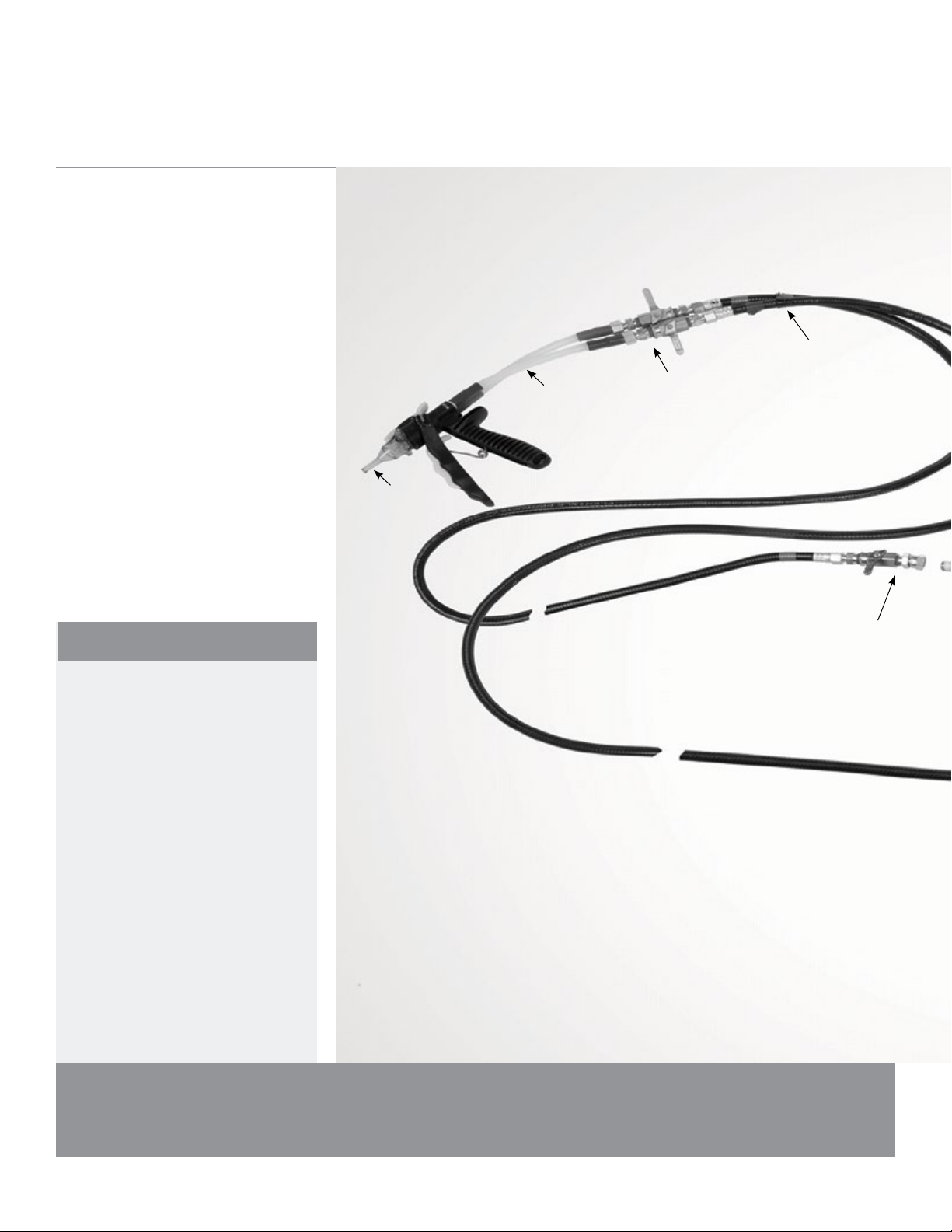
FROTHPAK™ Refill
System Installation
PRECAUTIONS:
DO NOT breathe vapor or spray. Proper
Personal Protective Equipment and
ventilation are required. See product
(Material) Safety Data Sheet ((M)SDS)
and Section 2 of this manual for further
information. Follow all precautions
for product.
INSTAFLO™
Gun
Anti-crossover
Nozzle
8 In. Hoses
In-line On-off
Ball Valves
30 Ft. Double nut
Chemical Hoses
On-off Swivel
Ball Valves
DO NOT expose container to
temperatures above 120
DO NOT incinerate, cut, puncture, or
weld on or near container.
DO NOT expose container to sparks
or flames.
A1
o
F (49oC).
Page 5
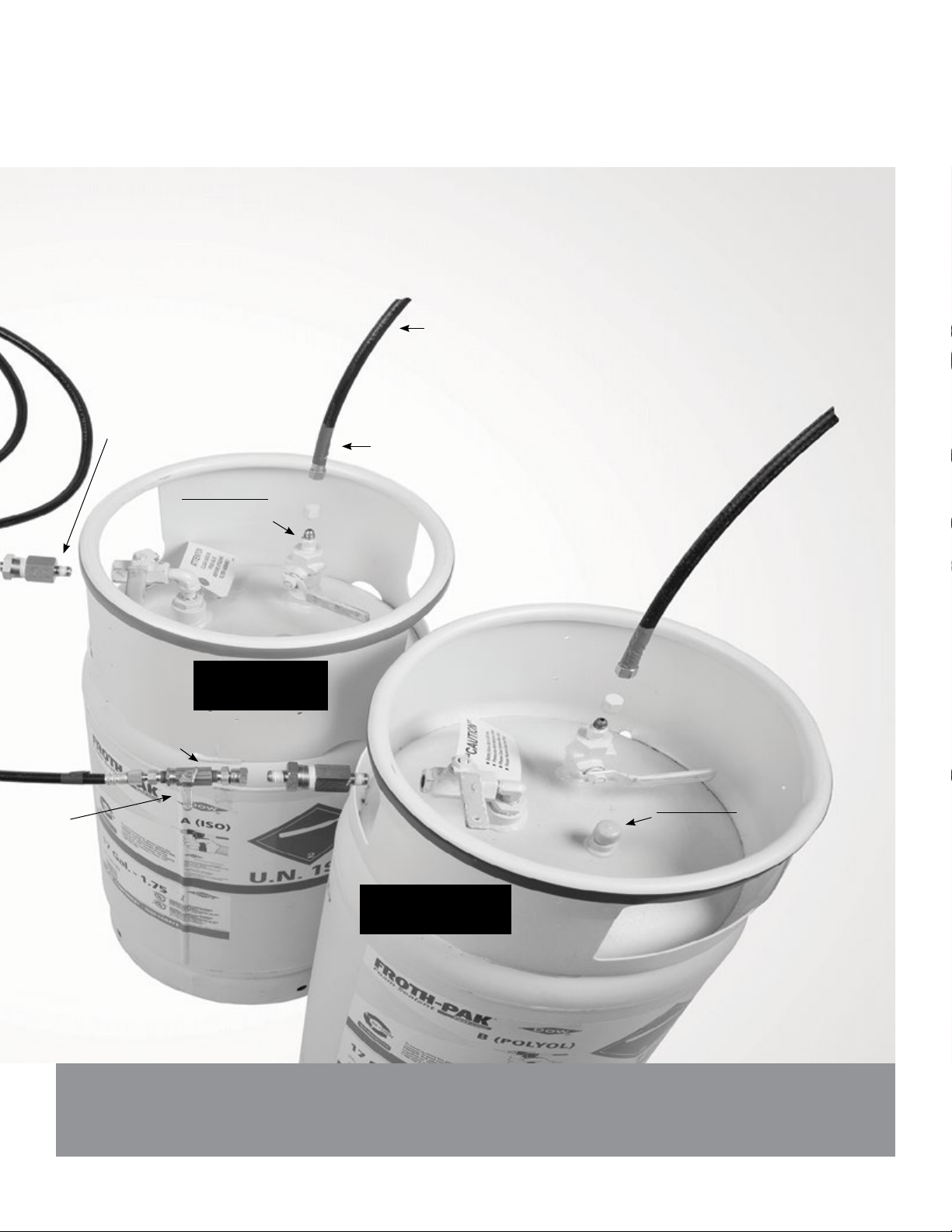
Nitrogen
Hoses
Dow Building Solutions
Chemical
Filter
Chemical
Filter
Tank Valves
Nitrogen
Intake Tank
Valves
Protective Plug: Remove and save
for return shipment of empty tanks.
“A” Tank
Protective Plug: Remove and save
for return shipment of empty tanks.
“B” Tank
A1
Page 6
Dow Building Solutions
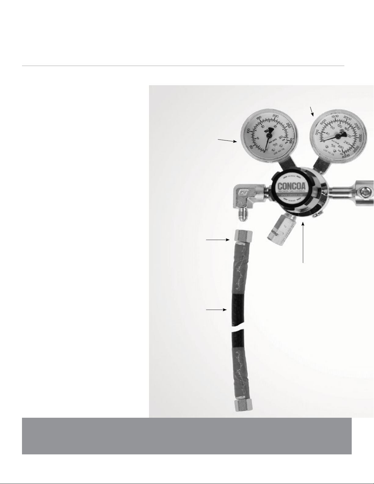
Nitrogen Regulator Assembly
(7.5 ft. nitrogen lines sold separately.
Two lines required for system operation)
Pressure Gauge
“A” Tank
Plastic Protective Cap.
(Remove before
attaching hoses)
Pressure Gauge
Nitrogen Cylinder
“A” Tank Nitrogen Hose
(mark hose ends
with yellow & red
electrical tape)
“A” Pressure Regulator
A2
Page 7
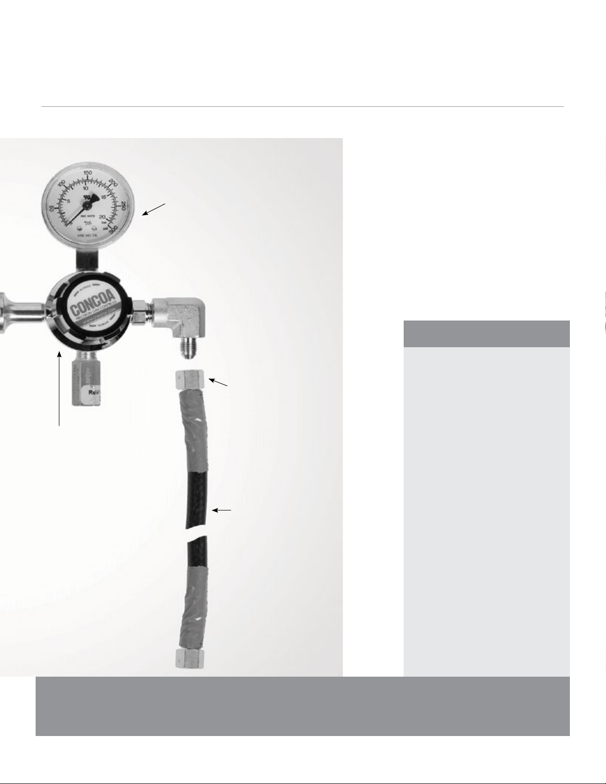
Pressure Gauge
“B” Tank
Dow Building Solutions
“B” Pressure Regulator
Plastic Protective Cap.
(Remove before
attaching hoses)
“B” Tank Nitrogen
Hose (mark hose
ends with yellow
& blue electrical tape)
WARNINGS:
NEVER use oxygen regulators on cylin-
ders of which the gas pressure exceeds
3000 pounds per square inch.
NEVER use oil or petroleum base grease
on regulator, inlet connection, or cylinder
valve. An explosion or fire could result. The
lubricant used on this regulator adjusting
screw is Dow-Corning No. 44 silicone
grease which is a non-petroleum base
grease.
NEVER stand in front of, or behind a
regulator while opening the cylinder valve.
DO NOT use WD40
INSTAFLO
®
Trademark of the WD40 Company.
™
Gun parts.
®
or DC44 on any
A2
Page 8
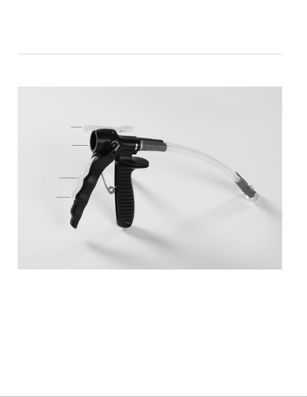
INSTAFLO™ Gun
Nozzle Ejector
Anti-crossover
Nozzle
Safety
Trigger
A3
Page 9
Dow Building Solutions
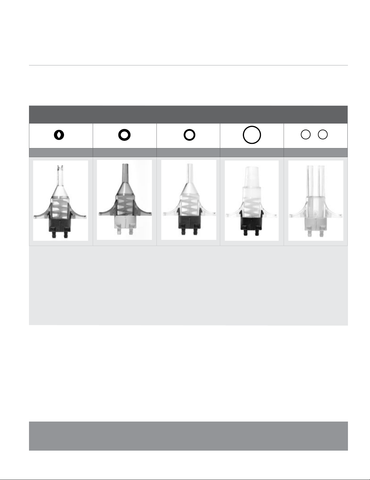
Anti-crossover Nozzles
(See page 3 for part numbers)
Fan Caulking Cone Pour Calibration
Nozzle Opening Nozzle Opening Nozzle Opening Nozzle Opening Nozzle Opening
A4
Page 10

Dow Building Solutions
Introduction
The FROTHPAK™ Refill System is a polyurethane foam
dispensing system for users who require large quantities of
foam. The system consists of “A” and “B” chemical tanks,
chemical filters, a high pressure regulator, nitrogen lines,
chemical dispensing hoses, and a Gun/Hose Assembly Kit.
The system requires dry nitrogen for chemical tank pressuriza-
tion and is not supplied.
The FROTHPAK™ Refill System is designed for
ease-of-use. The following instructions should be followed
strictly to ensure maximum equipment performance
and efficiency.
FROTHPAK™ Foam Insulation and Sealant
Application guidelines as provided by Dow Building Solutions should
be followed exactly in order to ensure compliance with building codes
and worker safety regulations. Read all information bulletins, (Material)
Safety Data Sheets ((M)SDS) and “Product Information” sheets. The SDS
is available at www.building.dow.com/na/en/literature/index.htm.
Application of this product is considered a “low pressure” process. It is
recommended that workers obtain spray foam training. Workers must be
respirator fit tested. Employers must have a documented respiratory and
personal protective equipment (PPE) plan. See Section 2 for further
PPE information.
Refill Systems
Manual
FROTHPAK™ Foam Insulation and Sealant contain isocyanate, polyol
and hydroflurocarbon blowing agents. See section 2 for further PPE
information. Do not breathe vapor or spray. Use only with supplied air
or an approved air purifying respirator equipped with an organic vapor
sorbent and a particle filter to maintain exposure levels below ACGIH,
OSHA, WEEL or other applicable limits. For situations where the atmospheric levels may exceed the level for which an air purifying respirator
is effective, use a positive-pressure air supplying respirator. The spray
foam applicator, and anyone within 25 feet of the applicator, must use
an approved air purifying respirator equipped with an organic vapor
sorbent and a particle filter at a minimum. If there is ever a doubt as to the
potential limits for worker exposure, Dow always recommends using the
highest level of worker protection. Additionally, use barrier tape to mark
the working perimeter and install warning signs.
It is important to ensure that the spray area is well ventilated during
application and one hour after spraying. Ventilation in Air Changes
per Hour (ACH):
• During application a minimum of 10 ACH is required. Cross
ventilation is recommended with negative pressure in the
spray area and exhaust to a secured empty area. A commercial
ventilation unit is recommended for increased ventilation rates.
• Continue to ventilate area for at least 1 hour after the job is
completed at no less than 10 ACH.
• Re-entry into an application site less than 1 hour post spray with
proper ventilation requires the use of an approved air purifying
respirator equipped with an organic vapor sorbent and a
particle filter.
• Ensure ventilation hose output is in a safe and secure location that
will not be accessible to individuals without proper PPE in a 25 foot
radius and is not near an air intake for a structure.
Safe Use and Training videos are available on line at:
http://building.dow.com/na/en/tools/training/
2
Page 11

System Information
1.1 Ordering Information
System Density / Type “A” Tank Part# / Color “B” Tank Part# / Color
1,2
17 Gallon System:
27 Gallon System:
60 Gallon System:
120 Gallon System:
350 Gallon System:
1 Formerly marked with a green colored stripe
2 Includes a Bill of Lading for tank return and a chemical filter
1.75 Foam Sealant
1.75 Foam Insulation (Class A)
1.75 Foam Sealant
1.75 Foam Insulation (Class A)
1.75 Foam Sealant
1.75 Foam Insulation (Class A)
1.75 Foam Sealant
1.75 Foam Insulation (Class A)
1.75 Foam Sealant
1.75 Foam Insulation (Class A)
341167 / white w/red stripe
340334 / white w/red stripe
1,2
11042106 / white w/green stripe
11042108 / white w/blue stripe
1,2
341165 / white w/red stripe
340337 / white w/red stripe
341168 / white w/red stripe
340336 / white w/red stripe
341166 / white w/red stripe
340338 / white w/red stripe
1,2
1,2
1,2
1,2
1,2
345347 / white w/blue stripe
11096260 / white w/purple stripe
1,2
11042107 / white w/green stripe
11096266 / white w/blue stripe
345344 / white w/blue stripe
11096263 / white w/purple stripe
345346 / white w/blue stripe
11096261/ white w/purple stripe
345348 / white w/blue stripe
11096264 / white w/purple stripe
Dow Building Solutions
1,2
1.2 Refill Accessories
Part# Description
158336 INSTAFLO™ Gun (1 - INSTAFLO™ Gun with 8” hoses)
158403
30 ft. Refill Gun/Hose Assembly Kit (1 - INSTAFLO™ Gun with 8” hoses, 2 - 30 ft. double nut hoses,
2 - on-off in-line ball valves, 2 - on-off swivel ball valves, 1 - wrench 9/16”)
238107 Nitrogen Regulator Assembly – (Requires two 7.5’ hoses – 158420)
158428 On/Off Valve, Chemical (Tank to hose)
158432 In Line On/Off Valve (Hose to dispenser)
158420 7.5 ft. Hose (Use single hose for chemical and/or nitrogen)
158421 15 ft. Hose (Buy in pairs for both A and B sides of chemical)
158422 30 ft. Hose (Buy in pairs for both A and B sides of chemical)
259202 Coupling - ACC Fitting 8 JIC (Connects hoses)
216151 Replacement Tank Filter
328507 ARCTIC PAK Wrap Heated Hose System (Includes wrap, controller assembly and extended length hose)
328508 ARCTIC PAK Wrap and Controller Assembly (Without hoses)
328509 ARCTIC PAK Wrap Controller Only
334489 ARCTIC PAK Replacement Hose Set (A and B side extended length hoses)
3
Page 12

Dow Building Solutions
1.3 Anti-crossover Nozzles (25 Pack)
Part# Output / Lbs. Min Nozzle Type Front / Back - Nozzle Color
259212 Low / 2lbs. Min Caulking Green / Yellow
259219
259211
259216
259218
259215
259217
259214
259220
259208
259210
259207
259206
Medium / 4lbs. Min
Medium / 4lbs. Min
Medium / 4lbs. Min
High / 67lbs. Min
High / 67lbs. Min
Highest / 810lbs. Min
Highest / 810lbs. Min
Highest / 810lbs. Min
Dual Stream
Dual Stream
Dual Stream
Dual Stream
1.4 Shipping Weights
System
Empty Tank with Fittings 60 lbs. Each
17 Gallon System:
Chemical 150 lbs. Net Each
Total Tank Weight 210 lbs. Each
Total System Weight 420 lbs
Empty Tank with Fittings 150 lbs. Each
27 Gallon System:
Chemical 239 lbs. Net Each
Total Tank Weight 389 lbs. Each
Total System Weight 780 lbs.
Empty Tank with Fittings 250 lbs. Each
60 Gallon System:
Chemical 500 lbs. Net Each
Total Tank Weight 750 lbs. Each
Total System Weight 1500 lbs.
Empty Tank with Fittings 400 lbs. Each
120 Gallon System:
Chemical 1125 lbs. Net Each
Total Tank Weight 1525 lbs. Each
Total System Weight 3050 lbs.
Empty Tank with Fittings 1000 lbs. Each
350 Gallon System:
Chemical 3200 lbs. Net Each
Total Tank Weight 4200 lbs. Each
Total System Weight 8400 lbs
Cone
Caulking
Fan
Cone
Fan
Cone
Fan
Pour
Calibration
Calibration
Calibration
Calibration
Clear / White (Included in FROTHPAK kits)
Green / White
Blue / White (Included in FROTHPAK kits)
Clear / Gray
Blue / Gray
Clear / Black
Blue / Black
Clear / Black
Clear / Yellow
Clear / White
Clear / Gray
Clear / Black
1.5 Tank Dimensions
Tank Size Dimensions
17 Gallon: 15” Diameter x 34” Height
27 Gallon: 14.5” Diameter x 44” Height
60 Gallon: 24” Diameter x 57” Height
120 Gallon: 30” Diameter x 59” Height
350 Gallon 76” Length x 41” Diameter x 54” Height
4
Page 13

1.6 Freight Classification for Tank Return
CAUTION:
The contents of both tanks are pressurized with Fluorinated
Hydrocarbons (HFC’s). The “A” tank contains polymeric
isocyanates and the “B” tank contains polyols with amines.
Mark each bill of lading as follows:
Full Tanks
CHEMICAL UNDER PRESSURE, N.O.S.
(1,1,1,2TETRAFLUOROETHANE),
Class 2.2, UN3500
Plastic Materials Other Than Expanded
NMFC#: 156240
ERG#: 126, Freight Class: 60
24-hour Emergency Contact Number:
Chemtrec 8004249300
Dow Building Solutions
Empty Tanks (17 gal., 27 gal., 60 gal., 120 gal.)
CHEMICAL UNDER PRESSURE, N.O.S.
(1,1,1,2TETRAFLUOROETHANE), Class 2.2, UN3500
Cylinders: NMFC#: 41160 SUB 3
ERG#: 126, Freight Class: 55
24-hour Emergency Contact Number:
Chemtrec 8004249300
Empty Tanks (350 gal. only)
CHEMICAL UNDER PRESSURE, N.O.S.
(1,1,1,2TETRAFLUOROETHANE), Class 2.2, UN3500
Tanks: NMFC # 181420 SUB 3
ERG#: 126, Freight Class: 85
24-hour Emergency Contact Number:
Chemtrec 8004249300
NOTE: Empty tanks should be marked “EMPTY”. A non-flammable gas label (green
diamond, Class 2) must be on each tank. Return bills of lading are provided on each
tank. An ‘X’ must be marked in the HM (hazardous materials) column.
All other appropriate information must be filled in as outlined above.
5
Page 14

Dow Building Solutions
Section 2
Safety Precautions
WARNING:
The FROTHPAK™ cylinders contain isocyanate, hydrofluorocarbon
blowing agent and polyols under pressure. Read and follow these
instructions and the Safety Data Sheets (SDSs) (formerly MSDSs or
Material Safety Data Sheets) carefully before use. The safety precautions
and personal protective equipment indicated below are designed to protect the user and allow for the safe use and handling of the spray system.
Follow all applicable federal, state, local and employer regulations.
IMPORTANT: Proper Personal Protective Equipment (PPE) consists
of respirator, chemical resistant gloves, protective suit with hood/coveralls, and chemical goggles which must be worn by all participants prior
to the nitrogen and chemical valves being opened and during operation.
2.1 Respiratory Protection
Workers must be respirator fit tested. Employers must have a
documented respiratory and PPE plan.
DO NOT breathe vapors or spray. Use only in a well ventilated area
with visible air movement away from the point of application. Depending
on the area of spray, the amount of foam being sprayed, the amount
of ventilation and the type of spray nozzle used, respiratory protection
equipment may differ in order to offer optimum protection to the
applicator from exceeding established exposure limits of isocyanate
and other components. Supplied air or an approved air purifying respirator equipped with an organic vapor sorbent cartridge and a P100
particulate filter may be required to maintain exposure levels below
ACGIH, OSHA, WEEL or other applicable limits. For situations where
the atmospheric levels may exceed the level for which an air-purifying
respirator is effective, use a positive-pressure, air supplying respirator
(air line or self-contained breathing apparatus). The spray foam applicator, and anyone within 25 feet of the applicator, must use approved
respiratory protection. If there is ever a doubt as to the potential limits
for worker exposure, Dow always recommends using the highest level
of protection. Use barrier tape and warning signs to mark the working
perimeter for respiratory hazards until 1 hour post spray.
• During application a minimum of 10 Air Changes per Hour (ACH) is
required. Cross ventilation is recommended with negative pressure
in the spray area and exhaust to a secured empty area. A commercial
ventilation unit is recommended.
• Continue to ventilate area for at least 1 hour after the job is completed
at no less than 10 ACH.
• Re-entry into an application site occurring less than 1 hour
post spray with proper ventilation requires the use of an approved
air purifying respirator equipped with an organic vapor sorbent
and a particle filter.
• Ensure ventilation hose output is in a safe and secure location that will
not be accessible to individuals without proper PPE in a 25 foot radius
and is not near an air intake for a structure..
2.2 Isocyanate-induced Occupational Asthma
Inhalation of vapors or mist at concentrations in excess of permissible
limits may result in an allergic respiration response and the development of sensitization. Skin contact with diisocyanates may play a role
in respiratory sensitization. Anyone who has been sensitized in the past
should not operate nor be in close proximity to the operation of these
systems as isocyante concentrations below exposure guidelines may
cause allergic respiratory reactions in individuals who are already sensitized. Asthma-like symptoms may include coughing, difficulty breathing,
and a feeling of tightness in the chest. Occasionally, breathing difficulties may be life-threatening. Follow all ventilation and PPE guidelines.
2.3 Safety Clothing
Personal Protection Equipment required when using
FROTHPAK™ includes chemical goggles and chemical resistant
gloves preferably made from nitrile, neoprene, butyl or PVC. Long
sleeves and pants or chemical resistant coveralls/protective suit with
hood should be worn. Shoe covers may also be worn.
2.4 Skin Contact
Avoid ALL contact with skin. May cause irritation or sensitization.
If skin contact occurs, remove contaminated clothing; carefully remove
uncured material without spreading; wash skin with soap and water. If
irritation occurs or persists, seek medical attention.
2.5 Eye Contact
Avoid ALL contact with eyes. Causes irritation. If contact with eyes
occurs, flush with clean, low pressure water for 15 minutes while
holding eyelids open. Seek medical attention.
6
Page 15

Dow Building Solutions
2.6 Ingestion
If swallowed, give large amounts of liquids. DO NOT induce vomiting.
Seek medical attention.
2.7 Removal of Cured Foam on Skin
FROTHPAK™ foam will adhere to most surfaces and skin. Avoid ALL
skin contact. Wear gloves and protective clothing. Cured foam is
difficult to remove. Cured foam must be mechanically removed or
allowed to wear off in time.
2.8 Overfilling Restricted Spaces
Avoid overfilling restricted spaces. The reaction of these chemicals
causes expansion and may exert enough force to cause an uncontrolled
stream of foam, spraying the work area and possibly the operator.
2.9 Chemical Information
For more specific information about the chemical components
“A” and “B”, refer to the appropriate SDS. KEEP OUT OF REACH
OF CHILDREN.
2.10 Chemical Spills
Consult SDS section 6 for Accidental Release Measures.
2.10.1 “A” Chemical
If “A” liquid spills from the tank, hose, or INSTAFLO™ Gun,
provide proper ventilation, wear all PPE and isolate the spill area.
Keep unnecessary and unprotected personnel from entering the
area. Dike the area and soak up the spill with an oil absorbent
material (vermiculite, sawdust, etc.). Neutralize the spillage area
with a solution of 90% water, 2% dishwashing detergent, and 8%
ammonia. The amount of this solution should be in excess of
the volume of the spill. Allow the mixture to react for at least
10 minutes. Collect in an open top waste container and treat
with additional ammonia solution. Remove the container to a
safe and secure location that will not be accessible to individuals
without proper PPE, loosely cover, and allow it to stand at least
24 hours. Dispose of the waste container in accordance with
federal, state, and local regulations.
2.10.2 “B” Chemical
If the “B” chemical spills from the tank, hose, or INSTAFLO Gun,
wear all PPE, dike and isolate the spill area. Keep unnecessary
and unprotected personnel from entering the area. Soak up the
residue from the surface with soap and water. Discard in accordance with federal, state, and local regulations.
2.11 Cautions
2.11.1 Storage Temperature
Recommended storage temperature:
60°– 80°F (16°–27°C).
Storage below 60°F (16°C) is not recommended.
Do not store at temperatures above 120°F (49°C).
2.11.2 Building Codes
In many areas, building codes may restrict the use of cellular
plastics or polyurethane foam in exposed, interior finishing
material applications. Under certain application code, the use of
these materials may be prohibited. The foam produced by this
product is organic and may constitute a fire hazard if improperly
applied. Consult local building codes.
2.11.3 Surface Temperature Restrictions
Polyurethane foam should not be used in direct contact with
chimneys, heat vents, steam pipes, or other surface areas that
exceed 240°F (116°C). The foam should not be left exposed or
inadequately protected for both interior and exterior finishing
materials. It is strongly recommended in all applications that the
foam be protected by approved facings and coatings.
2.11.4 Open Flame / Spark Source
Do not smoke or operate the system in close proximity
to an open flame or spark source. Ensure pilot lights are off.
Welding on or near cured polyurethane foam requires special
precautions. Consult The Dow Chemical Company for instructions.
2.11.5 Excessive Foam Dispensing
Do not apply excessive thicknesses at one time as this may result
in spontaneous combustion. For thickness greater than two
inches of cured foam, dispense foam in multiple layers, allowing
the heat from foaming to dissipate between sprayings.
2.12 Training
It is recommended that product users receive spray foam training.
Safe use and training videos are available at:
http://building.dow.com/na/en/tools/training/. For hands on
training information contact your Dow sales representative.
Further information is available at
http://www.spraypolyurethane.org/
7
Page 16

Dow Building Solutions
Section 3
System Installation
NOTE: Dry nitrogen is used for pressurizing the Refill System and is not supplied.
It may be obtained for a nominal rental charge from any local welding supplier.
Order standard size (industrial grade) cylinder with CGA 580 nitrogen fitting.
Refer to FROTHPAK™ Refill System Installation drawing, page A1.
3.1 Initial Tank Set-up
1) Be sure that the tanks are at the optimum temperature of
70 –80 degrees F., minimum 6065 degrees. If they are
below this range, utilize heating blankets or a box heater to
bring them up to the proper range. This is very important!
Consult your Dow Rep or Dow Technical Service if you
need assistance.
2) Color code all hoses with electrical tape (the nitrogen and
chemical transfer hoses, as well as the gun) red for the A Side
(ISO) and blue for the B Side (Polyol) to prevent chemical cross
contamination. Place colored tape at each end of the hoses for
proper identification.
3) Attach the nitrogen regulator to nitrogen tank.
a) Order a five (5) foot high nitrogen tank. At this height the
regulator is much easier to view.
b) Make sure nitrogen regulator handles are all turned out
(counterclockwise) until they cannot be turned any more.
This is the closed position.
c) Hand tighten the regulator to the tank and level the regulator
for easy viewing purposes.
d) Once level, fully tighten regulator with an adjustable wrench.
You will need about 30 lb-ft of force. Do not over tighten.
4) Attach the nitrogen hoses to the nitrogen regulator.
a) Remove the two protective caps from the nitrogen tank
regulator where the hoses will be connected.
b) The A side (red) should be on the operator’s left side as you
are facing the nitrogen tank/regulator. Attach red/yellow-
coded nitrogen hose to the regulator with about 30 lb-ft of
force. Do not over tighten.
c) Note that all the hose connections are flare fittings. These
do not require any sealant or Teflon tape. They just need to
be tight.
d) The B side (blue) should be on the operator’s right side as
you are facing the nitrogen tank/regulator. Attach blue/
yellow-coded nitrogen hose to the regulator with about
30 lb-ft of force. Do not over tighten.
5) Attach the nitrogen hoses to the chemical tank.
a) Remove cap covers from chemical tank connection on the
A side (red) and attach nitrogen hose to the flare fitting on
the valve that is in a vertical position (pointing straight up).
Tighten to about 30 lb-ft of force. Do not over tighten.
(Save the cap covers for when the tanks are returned
to Dow.)
b) Remove cap from chemical tank connection on the B side
(blue) and attach nitrogen hose to the flare fitting on the
valve that is a vertical position (pointing straight up). Tighten
to about 30 lb-ft of force. Do not over tighten. (Save the
cap covers for when the tanks are returned to Dow.)
6) Attach the filters to the chemical valve connections.
a) Remove the chemical valve plug on the A side (red). Save
the plug for return shipment to Dow, just leave inside
the ring on the top of the tank. On the A side only, it is
necessary to clean the petroleum jelly from the inside of the
valve with a cotton swab. (If you don’t have cotton swabs,
take the small cloth bag that the filter came in and wrap it
over the end of a screwdriver. Use this to clean the petro leum jelly out of the valve.) Next, connect the filter with the
arrow (arrow is engraved on the valve) flowing out or away
from tank and tighten to about 30 lb-ft. Note that the filter
is pipe thread and DOES need sealant or Teflon tape. It
should be taped from the factory but just check to be sure.
b) Remove the chemical valve plug on the B side (blue) from
the chemical tank. Save the plug for return shipment to
Dow, again just leave it in the ring on the top of tank.
Connect filter with arrow (arrow is embossed on the valve)
flowing out or away from tank and then tighten to about
30 lb-ft. Again, this is pipe thread and DOES require seal
ant or tape. Do not over tighten.
7) Attach the ball valves to the chemical filters.
a) At the end of the filter, attach a ball valve. Tighten both
ball valves on the A and B side to about 30 lb-ft but do not
over tighten. Again, this is pipe thread.
8) Attach the chemical hoses to the ball valve on the chemical
tanks.
a) Attach the A side (red) hose to the A side ball valve and make
sure to keep the ball valve in the upward position and in the
closed position. Tighten to about 30 lb-ft. Do not over
tighten.
8
Page 17

Dow Building Solutions
b) Attach the B side (blue) hose to the B side ball valve and
make sure to keep the ball valve in the upward position and
in the closed position. Tighten to about 30 lb-ft. Do not
over tighten.
9) Unroll chemical hoses and remove any kinks in the hose.
a) Attach the shutoff valves to the end of the hoses on the
A and B side. Make sure the arrow on the shutoff valves is
directed towards the gun. Tighten to about 30 lb-ft but do
not over tighten.
b) Attach the gun to the two shutoff valves at the end of the
hose. Keep the ball valve in the upward position and in the
closed position. Complete this for both the A and B sides.
c) Use black electrical tape to tape the A and B side hoses
together. Start this taping process at the gun end and work
your way back towards the tanks. Tape the hoses together
every 18 inches.
d) Tighten the ball valves to about 30 lb-ft but do not
over tighten.
e) At this point, check to make sure all hose, valve and filter
connections have been properly tightened to assure no
nitrogen or chemical leaks.
Note: If a 30’ hose extension is required, you will need to attach a coupling to the end
of the hose coming from the chemical tank and connect the hose sections together.
A standard ¼” male flare coupling from a hardware store works just fine. Tighten to
about 30 lb-ft but do not over tighten. Complete for both the A and B sides (total hose
length is not recommended to exceed 120 feet). Once the hose extensions have been
added, attach the shutoff valves to the end of the hose extensions where the gun is
connected.
Note: If you are using the Arctic Pak heated hose assembly, it is recommended that
you remove the yellow insulation during the summer months) from the hoses and store
it to prevent wear and tear on the insulation. This will extend the life of the insulation.
During the colder temperature months, place the yellow insulation back over the hoses.
If you remove the yellow insulation during the warm weather months, continue taping
the A and B side hoses together every 18 inches.
3.3 Nitrogen Regulator Information
1. Remove the orifice protector on the nitrogen cylinder.
Insert the nitrogen regulator assembly stem into the
orifice and hand tighten. Snug firmly using an adjust able wrench. Be careful not to strip the brass fitting.
2. Verify that the valve stems are freewheeling. This
indicates that the regulator stems are backed out.
3. Remove the thread protectors on the bottom of the
nitrogen regulator.
4. Connect a yellow & red-taped nitrogen line to the left
fitting on the nitrogen regulator assembly. Snug firmly
with an adjustable wrench.
5. Locate the yellow-coded nitrogen intake valve on the “A”
tank. Verify that the valve is closed. The handle should
be perpendicular to the valve. Loosen and remove the
nitrogen intake cap on the “A” tank.
6. Connect the other end of the yellow & red-taped-coded
nitrogen line to the nitrogen intake valve of the “A” tank.
Snug firmly with an adjustable wrench.
7. Connect the other yellow & blue-taped nitrogen line to
the right fitting on the nitrogen regulator assembly.
Snug firmly with an adjustable wrench.
8. Locate the yellow-coded nitrogen intake valve on the
“B” tank. Verify that the valve is closed. The handle should
be perpendicular to the valve. Loosen and remove the
nitrogen intake cap on the “B” tank.
3.2 Tank Positioning
1. Position the “A” tank to the left and the “B” tank to the
right. This is the standard in the polyurethane industry.
2. Place a nitrogen cylinder between the “A” and “B” tanks.
3. Secure the nitrogen cylinder to prevent it from falling
if bumped.
9. Connect the other end of the yellow & blue-taped coded
nitrogen line to the nitrogen intake valve of the “B” tank.
Snug firmly with an adjustable wrench.
9
Page 18

Dow Building Solutions
3.4 Chemical Hose Installation
1. Verify that the chemical tank valves are closed. The handle
should be perpendicular to the valve. Remove the chemical
valve plugs from the “A” and “B” tanks and place the plugs on
top of the tank.
2. Carefully remove all of the vaseline in the “A” chemical
tank valve.
3. Remove the chemical filters from the canvas bags on
top of each tank. Verify that the filter and the cartridge
are free by shaking the filter until you hear a clicking
sound.
NOTE: Air blown into end in the direction of arrow will pass
freely through the filter.
4. Connect a chemical filter to each tank valve with the
filter arrow pointing away from each tank. The arrow
represents the chemical flow. Tighten the filters with
an adjustable wrench. The filter prevents chemical
from flowing back into the tank.
5. Take the on-off valves with the swivel ends and
connect them to each tank filter. Tighten the connec tions with an adjustable wrench.
6. Uncoil the chemical lines. Tape them together every
few feet with tape.
7. Connect the “A” labeled chemical hose to the “A”
tank on-off valve. Tighten the connection with an
adjustable wrench.
8. Connect the other chemical hose to the “B” tank on-off
valve. Tighten the connection with an adjustable wrench.
9. Connect an in-line on-off valve to the other end of
each chemical hose. Verify that the arrow on each
valve points away from the hose being connected –
arrow indicates chemical flow. Tighten each connec tion with two adjustable wrenches.
10. Connect the Gun/Hose Assembly to the in-line valve
of each hose, “A” labeled hose to “A” labeled hose, the
unlabeled hose to the unlabeled hose. Tighten each
connection using two adjustable wrenches.
Section 4
Start-up Procedure
DO NOT breathe vapor or spray. Proper PPE and ventilation are
required. See product SDS and Section 2 of this manual for further
information. Follow all precautions for product.
4.1 System Pressurization
1. Verify that the valve stems on the regulator are backed
out and are freewheeling.
2. Open the nitrogen bottle valve by turning the knob
on top of the cylinder counterclockwise. If a hissing
sound occurs, further tighten the nitrogen regulator
valve stem with an adjustable wrench.
3. Verify the nitrogen cylinder pressure using the center
gauge of the nitrogen regulator assembly. The system
WILL NOT operate efficiently if the pressure falls below
500 psi. If below 500 psi, replace the nitrogen cylinder.
4. Turn the left regulator stem clockwise to the proper
pressure setting of the “A” tank (120160psi – Do not
go over 225psi) (see section 12). If a hissing sound
occurs, further tighten the yellow-coded nitrogen line
connection to the nitrogen regulator assembly and/or
the nitrogen intake valve connection on the “A” tank
using an adjustable wrench. If the left gauge fails to
indicate a pressure setting, contact your Dow Chemical
Sales Representative.
10
Page 19

Dow Building Solutions
5. Turn the right regulator stem clockwise to the proper
pressure setting of the “B” tank (120160 psi – Do not
go over 225psi) (see section 12). If a hissing sound
occurs, further tighten the yellow-coded nitrogen line
connection to the nitrogen regulator assembly and/or
the nitrogen intake valve connection on the “B” tank
using an adjustable wrench. If the right gauge fails to
indicate a pressure setting, contact your Dow Chemical
Sales Representative.
6. Slowly open the nitrogen intake valve of each tank.
The valve handles should be parallel with the
nitrogen lines.
7. Slowly turn on the chemical valve of each tank. The
valve handles should be parallel to the chemical lines.
Verify that the filter connection of each tank is tight
and that no chemical leaks are present.
8. Slowly turn on the on-off valves. The handles should
be parallel to the chemical lines. Verify that the
connections of each valve are tight and that no
chemical leaks are present.
9. Slowly turn on the in-line on-off valves. The handles
should be parallel to the chemical lines. Verify that
the connections of each valve are tight and that no
chemical leaks are present.
4. Know the bag weight so the weights may be subtracted
out of the total weight of the chemical, i.e.
180 divided by 162 equals 1.11 ratio
(A) (B)
Weight 188gms 170gms
Bag Weight -08gms -08gms
180gms 162gms
5. Place calibration nozzle in the dispenser. Before dispensing
material into bags, pull trigger to ensure material is
flowing properly through both tubes.
6. Hold two bags together, place one tube in each bag and pull
trigger for six to eight seconds.
7. Weigh bags separately. Always divide the weight of (B)
into the weight of (A). If the ratio is too high increase
the pressure of the “B” tank, and if the ratio is too
low increase the pressure of the “A” tank.
8. Most acceptable ratios are 1.10 to 1.20 for FROTHPAK
™
Class A Foam Insulation and 1.05 to 1.15 for FROTHPAK
Foam Sealant.
Pressure gauges in line with the regulator. Verify both sides. To verify corresponding
pressures of tanks, install pressure gauges in line with each tank. Perform this task on
the nitrogen inlet valve. Should pressure need to be reduced in a tank, slowly bleed off
pressure. NEVER bleed below 120 psi.
™
10. Remove the used nozzle by pushing down the
nozzle ejector.
4.2 Calibration Instructions
Equipment needed: PPE, scale capable of weighing in grams, paper
bags (lunch bags), calibration nozzles, and pressure gauges.
1. Ensure chemical temperature in tanks and lines are
70°F (21°C) or higher.
2. Set pressures at recommended settings (120160psi –
Do not go over 225psi).
3. Ensure chemical is flowing properly through dispenser
with a calibration nozzle in place.
9) Collect items needed for calibration (scale that weighs in
grams or ounces, lunch bags, marker, calculator, pen, writing
pad, petroleum jelly)
DO NOT breathe vapor or spray. Proper PPE and ventilation
are required. See product SDS and Section 2 of this manual for
further information. Follow all precautions for product.
10) Pressurize the system.
a) Fully open the valve on the nitrogen bottle.
b) Ensure the tank has at least 500 PSI pressure on
the main tank pressure gauge. If at or below this, order
a new tank. Do not operate under 300 PSI.
11
Page 20

Dow Building Solutions
c) Now set the A and B side regulators to their initial
pressure. Turn the handle clockwise to increase the
pressure. A good starting point is 160170 PSI on the
A Side and 140150 PSI on the B Side. Higher hose
lengths will require higher pressures. Follow the nitrogen
hoses to the tank and slowly open the nitrogen valves on
the tank to pressurize the tanks. You will hear the nitrogen
flowing as it pressurizes the cylinders. Check for nitrogen
leaks as you are pressurizing the tanks.
d) Slowly open the chemical valves on both the A and B
sides at the tanks to pressurize the hoses. For each side,
there are two valves to open; one valve at the tank and
one ball valve at the filter/hose connection. On the A-side,
open the tank valve first and then open the ball valve.
Repeat for the B side. Check for chemical leaks as you
are pressurizing the hoses.
Note: Should you experience any nitrogen or chemical leaks,
immediate close all chemical and nitrogen valves and correct the
situation before proceeding.
11. Check the gun to make sure it is working properly.
a) Open the two chemical valves at the gun. You will see
chemical flowing into the gun when they are opened.
b) Fully depress the gun trigger and spray the gun into a
lined waste receptacle to purge the gun and chemical
lines of nitrogen. You should see two good chemical
streams coming from the gun.
c) Spray GREAT STUFF PRO
™
gun cleaner into the face
of the gun to clean away any chemical residue. It is
important to keep the gun face clean to avoid plugging
of the chemical flow and to ensure that the nozzle makes
a leak proof connection.
d) Place a small amount of petroleum jelly on outside face
of gun where the nozzle fits in to ease the process of
attaching the nozzle. It is important that you do not
cover the chemical passage/orifices in the gun with
petroleum jelly.
12. Attach the appropriate calibration nozzle. The calibration
nozzle has 2 tubes protruding from the front of the nozzle.
For calibration purposes, the back cap color of calibration
nozzle should match the color of the spray nozzles that you
intend to use.
13. The nozzles are a tight fit. Typically you will hear two clicks.
Ensure that the yellow catch is fully latched over the
extension on the nozzle.
14. Label 2 bags; one bag A and one bag B. Place the A side
nozzle in the bag labeled A and the B side nozzle in the bag
labeled B. Fully depress the gun trigger and spray the
chemical into the 2 bags for 510 seconds or until the bags
are about 2/3 full.
15. Weigh the A side first and record the weight (in grams).
Next, weigh the B side and record the weight (in grams or –
be sure to use the same units on the A and B side).
16. Calculate the A to B ratio from the data you recorded. Enter
the A Side weight into the calculator and divide it by the B
Side weight. An A to B ratio of 1.10 to 1.20 is ideal.
17. Once the tank set has been calibrated, remove the calibration
nozzle, clean the gun face and insert the new spray nozzle
(of the same color). This calibration is good until the sets are
empty or until you need to replace the nitrogen tank as long
as there are no significant temperature changes to the tanks
and their contents. When in doubt, recalibrate.
Note: If the foam is off ratio (outside of the 1.10 to 1.20 range), adjustment of the
nitrogen regulator will be required.
™
• If the ratio is below 1.10 for FROTHPAK
FROTHPAK
• If the ratio is above 1.20 for FROTHPAK
FROTHPAK
• Do not operate the system above 220 PSI on either side, 200 PSI gives an even
larger safety factor to avoid opening the pressure relief valves on the tanks. If you
are near this pressure, then the pressure on the opposite side will need to be
reduced. So if the A Side is near 200 PSI and the ratio is still too high, bleed down
the B Side tank to increase the differential pressure between the tanks.
• To do this, shut the main nitrogen tank valve and shut the nitrogen inlet valve on
the product tank.
• Slowly loosen the nitrogen hose connection at the regulator. Do this slowly to let
the pressure bleed off.
• Hold the end of the hose in one hand and direct it towards the ground and away
from any people. With the other hand, slowly open the nitrogen inlet valve on
the tank to bleed down the pressure. Be patient and do this slowly. It may take a
few minutes. You do not need to bleed off all the pressure. Shut the tank valve.
™
Foam Sealant)
™
Foam Sealant).
Class A Foam Insulation (1.05 for
™
Class A Foam Insulation (1.15 for
12
Page 21

Dow Building Solutions
• Go back to the regulator for the hose you disconnected and turn the handle
counterclockwise all the way out.
• Reconnect the nitrogen line and tighten.
• Open the tank valve and read the pressure on the tank. It should be at least
40 – 50 PSI lower than when you started.
• Slowly turn the regulator handle clockwise until the pressure just starts to
increase. You are just bringing the regulator to the tank pressure. Now set the
pressure 20 – 30 PSI lower than when you last calibrated as a starting point.
When in doubt, go lower, you can easily increase it if needed.
Repeat as needed until the A to B ration is between 1.10 and 1.20.
Note: The pressure settings are just a starting point. There are many factors that
impact the actual ratio, including material temperature, hose age and possible partial
blockage, and gun condition. Likewise each set of gauges has a small range of
accuracy. The important thing to remember is that the ratio calculated during calibration is the FINAL WORD, the tank pressures are the means to get on ratio. If you need
to go outside the ranges listed above (assuming they are under 220 PSI MAX) that is
fine as long as you get the ratio in range.
4.3 System Purging and Testing
1. DO NOT breathe vapor or spray. Proper PPE and ventilation
are required. See product SDS and Section 2 of this manual
for further information. Follow all precautions for product.
2. Dispense chemicals in an appropriate container.
This is to verify proper chemical flow.
3. Clean any chemical from the INSTAFLO
using a rag.
4. Insert an unused nozzle with the key slot down.
Push in firmly until the nozzle ejector is seated over
the back rim of the nozzle.
™
Gun face
This chart is for the cone and fan type nozzles. Other
specialty nozzles may have different elapsed paused times.
Chemical Temp Elapsed Paused
Spraying Time
70°F (21°C) 35 Seconds
75°F (24°C) 30 Seconds
80°F (27°C) 25 Seconds
85°F (29°C) 20 Seconds
2. To replace the used nozzle, push down the nozzle
ejector. The used nozzle should eject.
3. Insert an unused nozzle with the key slot down.
Push in firmly until the nozzle ejector is seated over
the back rim of the nozzle. The refill system is ready
to operate.
Section 5
DO NOT breathe vapor or spray. Proper PPE and ventilation are
required. See product SDS and Section 2 of this manual for further
information. Follow all precautions for product.
5.1 Spraying
1. Once the calibration is complete, chose the nozzle with the
pattern and flow rate appropriate for the job. Attached
the nozzle.
5. Dispense foam to verify proper chemical mixing.
If improper mixing or poor foam quality, refer to the
Troubleshooting section, Section 10 of this manual.
4.4 Nozzle Replacement
1. The life of a nozzle depends on elapsed paused
spraying time and chemical temperature. Replace a
previously used nozzle if the elapsed paused spraying
time is exceeded using the chart on the right as a guide.
2. Practice on scrap material or plastic sheet to get the feel
of spraying and to ensure you are making good foam.
3. Hold the gun a consistent distance from the work and
perpendicular to the work. Move in a steady side to side
stroke. Avoid swinging the gun, it will result in variable thick nesses of foam. The speed of your movement and the dis-
tance from the work will determine the thickness of the foam.
4. Always fully engage the trigger of the gun. Partial engage ment can result in off ratio foam.
13
Page 22

Dow Building Solutions
5. Let the foam cure (a minute or two) Look for an even tan
color foam. Watch to see that it rises 3 or 4 times the original
thickness. Make sure the foam has cured and is firm.
6. If the foam looks unusual, verify the calibration settings and
that the tanks are 70 – 80 degrees. (Minimum 60 – 65
degrees). Then remove the nozzle and purge material into a
waste container for 15 – 30 seconds. Clean the face of the
gun, insert a new nozzle and perform a test spray again.
7. If problems persist call your Dow rep or Dow Technical service.
8. While spraying, always watch for signs of unusual looking
foam. Troubleshoot as outlined above.
9. Watch for any bubbles in the translucent hoses near the
gun and listen for any sputtering. This may be a sign of an
empty tank.
5.2 INSTAFLO™ Gun Operation
The INSTAFLO Gun provides greater flow control and minimizes
waste when used properly. The following operating instructions ensure
maximum efficiency and performance of the INSTAFLO Gun.
1. DO NOT breathe vapor or spray. Proper PPE and ventilation
are required. See product SDS and Section 2 of this manual
for further information. Follow all precautions for product.
2. To insert an unused nozzle, verify that the key slot on the
nozzle is in the down position. Push in firmly until the nozzle
ejector is seated over the back rim of the nozzle.
This chart is for the cone and fan type nozzles. Other specialty
nozzles may have different elapsed paused spraying times.
Chemical Temp Elapsed Paused
Spraying Time
70°F (21°C) 35 Seconds
75°F (24°C) 30 Seconds
80°F (27°C) 25 Seconds
85°F (29°C) 20 Seconds
5. When spraying is completed, remove the used nozzle
by pushing down on the nozzle ejector.
6. Apply petroleum jelly to the face of the INSTAFLO Gun.
7. Reinsert the used nozzle. This provides an airtight seal
during storage.
Refer to INSTAFLO™ Gun drawing, page A3
Section 6
Shut Down
1. When shutting down the refill system for the day, leave the
cured nozzle attached to the gun to keep moisture from
penetrating the hoses.
2. Shut off the A and B side valves on gun and the two sets of
valves on the chemical tanks for the A and B sides.
3. To meter the INSTAFLO
™
Gun, engage the trigger
one-third to one-half. This should be done sparingly
due to the ratio of the foam being affected.
4. The life of a nozzle depends on elapsed paused spraying time
and chemical temperature. Replace a previously used nozzle
if the elapsed paused spraying time is exceeded using the
chart on the right as a guide.
14
3. Leave all hoses attached.
4. Shut off the main nitrogen valve at the nitrogen tank. Do not
adjust the regulator levels that were established during cali bration. These settings can be used until the chemical tanks
are empty or the nitrogen tank is replaced as long as there
are no big temperature swings.
Page 23

Dow Building Solutions
Shut-down Procedure
1. Remove the used nozzle by pushing down on the
nozzle ejector.
2. Apply petroleum jelly to the face of the INSTAFLO™ Gun.
3. Reinsert the used nozzle. This provides an airtight
seal during storage.
4. Turn off the in-line on-off valves. The valve handles
should be perpendicular to the chemical lines.
5. Turn off the on-off valves located near the chemical filters.
The valve handles should be perpendicular to the
chemical lines.
6. Turn off the chemical tank valves of the “A” and “B” tanks. The
handles should be perpendicular to the valves.
7. Turn off the yellow-coded nitrogen intake valves of the “A” and
“B” tanks. The handles should be perpendicular to the valves.
8. Turn off the nitrogen cylinder by turning the valve on the top
of the nitrogen cylinder in a clockwise direction.
9. Back out both nitrogen regulator valve stems until they are
freewheeling.
10. Coil the chemical lines to prevent possible tripping
and damage.
6. DO NOT store near chimneys or heat vents.
7. If a partially used system remains inactive for a period of time,
the system should be pressurized and purged every two weeks.
This will prevent crystallization of the chemical in the hoses.
8. Unopened chemical tanks have a shelf life of approximately
one year.
Section 8
DO NOT breathe vapor or spray. Proper Personal Protective Equipment
and ventilation are required. See product SDS and Section 2 of this
manual for further information. Follow all precautions for product.
Re-Start-Up
1. Open the nitrogen valve fully to pressurize the system.
2. Open the two sets of valves on the chemical tanks for the A and
B sides and then the valves on the gun.
3. Remove the cured nozzle that you left attached to the gun.
4. Spray into a waste container. Ensure that you have good flow
from both the A and B side hoses.
5. Clean the face of the gun. Attach a new nozzle.
6. Spray a test sample to ensure good quality foam.
Section 7
Storage
1. Store in a dry area.
2. Store between 60°–80°F (16°–27°C).
3. Short term storage between 45°–60°F (7°–16°C) is permitted.
4. DO NOT store at temperatures above 120°F (49°C).
5. DO NOT not store near steam or hot water pipes.
7. Resume spraying.
Re-start Procedure
8.1 System Pressurization
1. Verify that the valve stems on the regulator are backed
out and are freewheeling.
2. Open the nitrogen bottle valve by turning the knob on top of
the cylinder counter-clockwise. If a hissing sound occurs,
further tighten the nitrogen regulator valve stem with an
adjustable wrench. Use only in well ventilated areas. Wear
suitable respiratory protection.
15
Page 24

Dow Building Solutions
3. Verify that the nitrogen cylinder pressure using the center
gauge of the nitrogen regulator assembly. The system WILL
NOT operate efficiently if the pressure falls below 500 psi.
If below 500 psi, replace the nitrogen cylinder.
4. Turn the left regulator stem clockwise to the proper
pressure setting of the “A” tank (120160psi – Do not go
over 225psi) (see section 12).
If a hissing sound occurs, further tighten the yellow/red-
coded nitrogen line connection to the nitrogen regulator
assembly and/or the nitrogen intake valve connection on the
“A” tank using an adjustable wrench. If the left gauge fails
to indicate a pressure setting, contact your Dow Sales
Representative.
5. Turn the right regulator stem clockwise to the proper
pressure setting of the “B” tank (120160psi – Do not
go over 225psi) (see section 12).
If a hissing sound occurs, further tighten the yellow/blue coded nitrogen line connection to the nitrogen regulator
assembly and/or the nitrogen intake valve connection on the
“B” tank using an adjustable wrench. If the right gauge fails
to indicate a pressure setting, contact your Dow Sales
Representative.
6. Slowly open the nitrogen intake valve of each tank. The valve
handles should be parallel with the nitrogen lines.
7. Slowly turn on the chemical valve of each tank. The valve
handles should be parallel to the chemical lines. Verify that
the filter connection of each tank is tight and that no chemical
leaks are present.
8. Slowly turn on the on-off valves. The handles should be
parallel to the chemical lines. Verify that the connections of
each valve are tight and that no chemical leaks are present.
9. Slowly turn on the in-line on-off valves. The handles should
be parallel to the chemical lines. Verify that the connections of
each valve are tight and that no chemical leaks are present.
8.2 System Purging and Testing
1. DO NOT breathe vapor or spray. Proper PPE and ventilation
are required. See product SDS and Section 2 of this manual
for further information. Follow all precautions for product.
2. Dispense chemicals in an appropriate container.
This is to verify proper chemical flow.
3. Clean any chemical from the INSTAFLO™ Gun face
using a rag or paper towel.
4. Insert an unused nozzle with the key slot down. Push
in firmly until the nozzle ejector is seated over the
back rim of the nozzle.
5. Dispense foam to verify proper chemical mixing.
If improper mixing or poor foam quality, refer to the
Troubleshooting section, Section 10 of this manual.
Section 9
Tank Change-over
1. DO NOT breathe vapor or spray. Proper PPE and ventilation
are required. See product SDS and Section 2 of this manual
for further information. Follow all precautions for product.
2. Putting on a fresh set of tanks is essentially the same process
as the initial start-up. One big difference is that the lines have
chemicals in them. If exposed to the atmosphere for more
than a few minutes, the A Side line will become plugged. So
keep the lines hooked up to the empty tanks until you are
ready to put on the fresh set.
3. Double check that the nitrogen tank is above 500 PSI.
4. Prep the new tanks as outlined above right to the point of
hooking up lines.
10. Remove the used nozzle by pushing down the nozzle ejector.
16
Page 25

5. When ready for this, be sure the tank valves are closed on
the empty tanks. Bleed off any pressure in the lines by pulling
the trigger of the gun while aimed into a waste container.
6. Disconnect the lines and transfer to the new set. Be sure to
have on proper protective equipment as some residual
material will be in the lines.
7. Back out the regulator valve handles (counterclockwise) and
then proceed with the calibration process as outlined above.
8. Replace the plugs and caps on the tank connections. Attach
the Bill of Lading to the empty tanks and call them in to be
picked up along with the paperwork that came with the tanks.
9. Remove the used nozzle by pushing down on the
nozzle ejector.
Dow Building Solutions
9.1 “A” Tank Change-over
1. Position the new “A” tank next to the empty “A” tank.
2. Verify that the nitrogen intake and chemical valves
of the new “A” tank are closed. The handles should be
perpendicular to the valves.
3. Remove the yellow-coded cap on the nitrogen intake
valve of the new “A” tank.
4. Relieve the nitrogen pressure by loosening and
removing the yellow/red coded nitrogen regulator line
from the nitrogen intake valve of the empty “A” tank
using an adjustable wrench.
5. Reconnect the “A” yellow/red coded nitrogen line to the
nitrogen intake valve of the new “A” tank. Tighten the
connection with an adjustable wrench.
10. Turn off the chemical tank valves. The handles should
be perpendicular to the valves.
11. Depressurize the chemical lines by engaging the trigger,
dispensing the chemical in an appropriate container.
12. Clean any chemical on the INSTAFLO™ Gun face
with a rag.
13. Turn off the on-off valves located near the tank filter.
The valve handles should be perpendicular to the
chemical lines.
14. Turn off the yellow-coded nitrogen intake valves of
the “A” and “B” tanks. The handles should be perpen dicular to the valves.
15 Turn off the nitrogen cylinder by turning the valve in
a counter-clockwise direction.
16. Back out both nitrogen regulator valve stems until
they are freewheeling.
6. Remove the chemical valve plug of the new “A” tank
and place the plug on top of the new “A” tank.
7. Carefully remove the vaseline in the “A” chemical
tank valve.
8. Remove the fluid filter from the canvas bag on top of
the new “A” tank. Verify that the filter and the cartridge are
free by shaking the filter until you hear a “clicking sound”.
NOTE: Air blown into end in the direction of arrow will pass freely through
the filter.
9. Connect the filter to the new “A” tank chemical valve with the
filter arrow pointing away from the tank. The arrow represents
the chemical flow. Tighten the filter with an adjustable wrench.
The filter prevents chemical from flowing back into the tank.
CAUTION: When disconnecting chemical lines, always cover the
connections with a rag to minimize chemical spray or spillage.
10. Disconnect the “A” on-off valve from the filter of the
empty “A” tank, covering the connection with a rag.
17
Page 26

Dow Building Solutions
11. Reconnect the “A” on-off valve to the filter of the new
“A” tank. Tighten with an adjustable wrench.
12. Remove the filter from the empty “A” tank and
dispose accordingly.
13. Reconnect the plug on the empty “A” tank to the
chemical valve. Tighten with an adjustable wrench.
14. Depressurize the empty “A” tank by slowly opening
the nitrogen intake valve.
15. When the tank has been depressurized, close the nitrogen
intake valve of the empty “A” tank and reconnect
the yellow-coded cap. Tighten with an adjustable wrench.
16. Remove the empty “A” tank and position the new “A”
tank in its place.
17. Write “EMPTY” on the empty “A” tank
9.2 “B” Tank Change-over
1. Position the new “B” tank next to the empty “B” tank.
2. Verify that the nitrogen intake and chemical valves of
the new “B” tank are closed. The handles should be
perpendicular to the valves.
3. Remove the yellow-coded cap on the nitrogen intake
valve of the new “B” tank.
4. Relieve the nitrogen pressure by loosening and removing
the yellow/blue coded nitrogen regulator line from the
nitrogen intake valve of the empty “B” tank using an
adjustable wrench.
5. Reconnect the “B” yellow/blue coded nitrogen line to the
nitrogen intake valve of the new “B” tank. Tighten the
connection with an adjustable wrench.
6. Remove the chemical valve plug of the new “B” tank and
place the plug on top of the new “B” tank.
7. Remove the fluid filter from the canvas bag on top of the
new “B” tank. Verify that the filter and the cartridge are
free by shaking the filter until you hear a “clicking sound.”
NOTE: Air blown into this end will pass freely through the filter.
8. Connect the filter to the new “B” tank chemical valve
with the filter arrow pointing away from the tank. The
arrow represents the chemical flow. Tighten the filter
with an adjustable wrench. The filter prevents
chemical from flowing back into the tank.
CAUTION: When disconnecting chemical lines, always cover the
connections with a rag to minimize chemical spray or spillage.
9. Disconnect the “B” on-off valve from the filter of the
empty “B” tank, covering the connection with a rag.
10. Reconnect the “B” on-off valve to the filter of the new
“B” tank. Tighten with an adjustable wrench.
11. Remove the filter from the empty “B” tank and
dispose appropriately.
12. Reconnect the plug on the empty “B” tank to the
chemical valve. Tighten with an adjustable wrench.
13. Depressurize the empty “B” tank by slowly opening
the nitrogen intake valve.
14. When the tank has been depressurized, close the
nitrogen intake valve of the empty “B” tank and
reconnect the yellow-coded cap. Tighten with an
adjustable wrench.
15. Remove the empty “B” tank and position the new “B”
tank in its place.
16. Write “EMPTY” on the empty “B” tank.
9.3 Tank Return
1. Complete the bill of lading on the empty tanks as
described on page 5 of this manual.
18
Page 27

Dow Building Solutions
9.4 System Pressurization
1. Open the nitrogen bottle valve by turning the knob
on top of the cylinder counter-clockwise. If a hissing
sound occurs, further tighten the nitrogen regulator
valve stem with an adjustable wrench.
2. Verify that nitrogen cylinder pressure using the center
gauge of the nitrogen regulator assembly. The system
WILL NOT operate efficiently if the pressure falls below
500 psi. If below 500 psi, replace the nitrogen cylinder.
3. Turn the left regulator stem clockwise to the proper
pressure setting of the “A” tank (120160psi – Do not
go over 225psi). If a hissing sound occurs, further
tighten the yellow-coded nitrogen line connection to
the nitrogen regulator assembly and/or the nitrogen
intake connection on the “A” tank using an adjustable
wrench. If the left gauge fails to indicate a pressure
setting, contact your Dow Sales Representative.
4. Turn the right regulator stem clockwise to the proper
pressure setting of the “B” tank (120160psi – Do not go
over 225psi). If a hissing sound occurs, further tighten the
yellow-coded nitrogen line connection to the nitrogen
regulator assembly and/or the nitrogen intake valve
connection on the “B” tank using an adjustable wrench.
If the right gauge fails to indicate a pressure setting,
contact your Dow Sales Representative.
3. Insert an unused nozzle with the key slot down. Push in
firmly until the nozzle ejector is seated over the back rim of
the nozzle.
4. Dispense foam to verify proper chemical mixing. If improper
mixing or poor foam quality, refer to the Troubleshooting
section, Section 10 of this manual.
Section 10
Troubleshooting
The FROTHPAK™ Refill System is virtually maintenance-free and
many problems can be corrected through simple troubleshooting
techniques. When troubleshooting, confirm that the system is pressurized correctly, and that all nitrogen and chemical valves are in the open
position. One closed valve can cause a system shut-down.
10.1 Temperature
Chemical temperature can affect foam quality. If the chemical temperature is below 65
temperature range is 70
10.2 Foam Color and Quality
Changes in foam quality indicate an off-ratio foam. If the foam is crusty
after curing, the foam is “A” rich and a blockage of “B” chemical exists.
°F (18°C), poor quality foam may result. The ideal
°-90°F (21°-32°C).
5. Slowly open the nitrogen intake valve of each tank.
The valve handles should be parallel with the nitrogen lines.
6. Slowly turn on the chemical valve of each tank and the on-off
valve of each chemical line. The valve handles should be
parallel to the chemical lines. Verify that the filter connection
of each tank is tight and that no chemical leaks are present.
9.5 System Purging and Testing
1. Dispense chemicals in an appropriate container.
This is to verify proper chemical flow.
2. Clean any chemical from the INSTAFLO™ Gun face
using a rag.
If the foam is mushy, and remains soft after two minutes, the foam is “B”
rich and a blockage of “A” chemical exists.
To identify and correct the problem, initiate the following procedure:
1. DO NOT breathe vapor or spray. Proper PPE and ventilation
are required. See product SDS and Section 2 of this manual
for further information. Follow all precautions for product.
2. Remove the used nozzle by pushing down the nozzle
ejector. Use only in well ventilated areas. With insuf-
ficient ventilation, wear suitable respiratory protection.
19
Page 28

Dow Building Solutions
3. Dispense chemicals in an appropriate container and
examine the chemical streams. If the streams are
equal, the problem existed in the nozzle. Continue
with steps 47 below. If the problem is not corrected,
the blockage exists in the system. Continue with
CAUTION – below step 7.
4. Clean any chemical from the INSTAFLO™ Gun face
using a rag.
5. Insert an unused nozzle.
6. Dispense chemical in an appropriate container.
7. Check the quality of the foam. If the foam is good,
the system is ready to operate. If the problem is not
corrected, the blockage exists in the system.
(Continued from step 3)
CAUTION: When disconnecting chemical lines, always
cover the connections with a rag to minimize chemical
spray or spillage.
8. Turn off the “A” and “B” lines with the in-line on-off
valves. The valve handles should be perpendicular to
the chemical lines.
9. Depressurize the Gun/Hose Assembly by pulling
the trigger, dispensing chemicals in an appropriate
container.
10. Disconnect the INSTAFLO Gun from the in-line on-off
valve using two adjustable wrenches.
11. While holding the chemical line over an appropriate
container, carefully open the valve of the “A” hose
and dispense chemical into the container. Check the
flow. Repeat for the ‘B’ hose.
12. If the flow was adequate from both hoses, the problem
was with the INSTAFLO™ Gun/Hose Assembly.
Discard the old INSTAFLO Gun/Hose Assembly and
replace with a new one according to steps 1320.
If a blockage persists, continue with step 21.
13. Connect the new INSTAFLO Gun/Hose Assembly.
14. Tighten all connections with two adjustable wrenches.
15. Verify that all chemical line valves are on. The valve
handles should be perpendicular to the chemical lines.
16. Dispense chemicals in an appropriate container to
verify proper chemical flow.
17. Clean any chemical from the face of the INSTAFLO
Gun with a rag.
18. Insert an unused nozzle with the key slot down. Push
in firmly until the nozzle ejector is seated over the
back rim of the nozzle.
19. Dispense chemicals in an appropriate container.
20. Check the quality of the foam. If the foam quality is
good, the system is ready to operate. If problems
persist, go back to step 2.
21. Turn off the on-off valve located near the tank filter
of the blocked line.
22. Turn on the in-line on-off valve of the blocked line
to depressurize the hose, allowing the chemical to
dispense in an appropriate container.
23. Close the in-line on-off valve when the hose has
depressurized.
24. Disconnect the obstructed chemical hose from the
on-off valve located next to the tank filter.
20
Page 29

25. Re-open the on-off valve located near the filter and
allow the chemical to flow in an appropriate container.
If the chemical flow is unobstructed, the blockage
exists in the chemical hose which must be replaced.
26. If the blockage persists, examine the tank filter. The
arrow on the filter should be pointing away from the
tank. If not, change the filter direction, steps 3141. If
the filter was installed correctly, continue with step 42.
Dow Building Solutions
Section 11
Yield Notes
Board foot yields are based on the free rise of the total weight of
the chemicals in the tanks. Many factors affect the yield in field
applications.
11.1 Operator Technique
For best results, apply multiple layers of foam. When spraying,
apply one-quarter to one-half inch thickness of uncured foam.
This will produce a one to one-and-one-half inch thickness of
fully cured foam.
27. Close the on-off valve.
28. Close the chemical tank valve.
29. Open the on-off valve located near the filter to
depressurize the filter.
30. Disconnect the on-off valve from the filter.
31. Disconnect the filter from the chemical tank valve.
32. Reconnect the new filter with the arrow pointing away
from the tank.
33. Reconnect the on-off valve with the swivel to the filter.
34. Tighten all connections with an adjustable wrench.
35. Verify that the on-off valve is closed. The handle should be
perpendicular to the valve.
36. Open the chemical tank valve.
37. Open the on-off valve and allow the chemical to
flow in an appropriate container. If the flow is full,
reconnect the chemical hose and Gun/Hose Assembly
and perform steps 1623. If the flow is weak the problem
exists in the tank. Contact your Dow Sales Representative
for assistance.
11.2 Application
Avoid spraying over rising foam.
11.3 Temperature
To ensure proper chemical mix, reaction, cure, and optimum
yields, chemicals should not be dispensed if the chemical
temperature is below 65°F (18°C). Insufficient operating
temperatures can cause improper mix, extend cure time, and
adversely affect final physical properties and yields.
NOTE: When using polyurethane foam, estimate 30% more foam than is
required. This yield buffer is recommended so that you will not run out of
chemical on a job site.
21
Page 30

Dow Building Solutions
Section 12
Ratios and Output
Density PSI (A / B) Nominal
Output*
1.75 120 / 120 3.6 lbs/min 1.0 : 1.0
1.75 140 / 140 4.0 lbs/min 1.0 : 1.0
*Using cone type nozzle with chemicals at 75°F (24°C). Do not increase pressure over
225psi. PRV set @ 250psi.
NOTE: Checking the system output and chemical ratio can determine whether the
system is in good operating condition. A system blockage for example, is indicated
by an abnormally low output. Checking the ratio can indicate whether the problem is
related to the “A” or “B” side. The ratios and outputs for other products are similar to the
results listed above. However, temperatures lower than 65°F (18
gauge on the nitrogen regulator assembly may cause substantial deviation.
Nominal Ratio
(A : B)
°C) or a faulty pressure
Section 13
Anti-crossover Nozzles
The Dow Chemical Company provides various anti-crossover nozzles
with various spray patterns for use with the INSTAFLO™ Gun. For best
results, operate the INSTAFLO Gun between 6 and 36 inches from
the surface being sprayed. Move the INSTAFLO Gun in a steady but
relatively slow back and forth motion. This will provide an even coverage.
Do not spray over rising foam.
Section 14
Nitrogen Regulator
14.1 Important - Safety Information
1. NEVER use regulators on cylinders of which the gas
pressure exceeds 3000 pounds per square inch
2. NEVER set chemical tank pressure over 225psi.
3. NEVER use oil or petroleum base grease on regulator,
inlet connection, or cylinder valve. An explosion or
fire could result. The lubricant used on this regulator
adjusting screw is Dow-Corning No. 44 silicone grease
which is a non-petroleum base grease.
4. NEVER stand in front of, or behind a regulator while
opening the cylinder valve.
14.1.1 Instructions
1. Before attaching the regulator to the nitrogen cylinder valve
outlet, open the valve for a few seconds, allowing the
gas to force out any possible foreign matter.
2. Attach the regulator to the Nitrogen cylinder valve and
tighten the inlet nut securely with an adjustable wrench.
3. Before opening the cylinder valve, turn the adjusting
screws (valve stems) to the left until no tension is felt.
The cone type nozzle provides a round spray pattern for multiple
applications and surfaces.
The fan type nozzle provides a fine fan spray pattern resulting in a
smooth foam surface (paint spray finish).
The caulking type nozzle provides a bead pattern for ultra fine coverage
and has less overspray.
Refer to INSTAFLO Gun and Anti-Crossover Nozzle drawings, pages A3A4.
22
NOTE: NEVER open cylinder valve until spring tension on the valve
stems have been released.
4. Open cylinder valve slowly. DO NOT stand in front of
or behind regulator while opening the cylinder valve.
5. Turn valve stems clockwise until the low pressure gauge
registers the desired working pressure.Nitrogen Regulators
are available through The Dow Chemical Company or:
Airgas North Central Inc.
1250 W. Washington Street
West Chicago, IL 60185
Phone: (630) 2319260
Refer to Nitrogen Regulator Assembly drawing, page A2. The regulator is not pressure
releasing - turning the regulator to a lower psi will not reduce pressure in the tank until the
pressure is manually vented.
Page 31

Section 15
Tank Heating
15.1 Usage
In places where the FROTHPAK™ Refill System is used where the
ambient temperature is below 65°F (18°C), an external source to heat
the chemical in the tanks may be required.
Heating bands are available for both the 17 gallon and the 60 gallon
tanks, through:
McMaster-Carr
www.mcmaster.com
6306003600
The heater band McMaster model numbers are as follows:
17 gallon: 3545K42
60 gallon: 3545K44
Control boxes are available through:
Glas-Col Apparatus Company
711 Hulman Street, P.O. Box 2128
Terre Haute, IN 47802
812 - 235 - 6167
The model number for the control box is PL312.
During the initial start-up, the controls for the heater bands can be set at
3 or 4 for two hours. However, for continuous operation, “LO” would be
the desired setting, unless extremely low temperatures are experienced.
15.2 Installation Procedure - Tank Heater Band
1. Wrap and clamp heater band around tank prior to switching on.
2. Pull on spring, at the same time hold end of heater
against the tank.
Dow Building Solutions
15.3 POWERBLANKET® warming equipment
POWERBLANKET warming equipment also keeps your jobs on
schedule during the colder months. Delivering a barrier of insulated
heat to the spray foam. Powerblanket creates an optimal application
environment. For more information, call Customer Service at
8773987407. To order, call 8014568013 and refer to the item
numbers below:
• DOW17 (17-gallon tank heater)
• DOW27 (27-gallon tank heater)
• DOW60 (60-gallon tank heater)
• DOW620 (620& 650 -bf single-component cylinder heater)
• DOW200 (200 & 210 -bf A & B disposable box heater)
• DOW55RR (Rapid Ramp 55-gallon drum heater)
• DOW55PRO (Pro series 55-gallon drum heater
and thermostatic controller)
• DOWGHT (Digital thermostatic controller)
15.4 Glas-Col Power Control Description and Operation
The Glas-Col Minitrol is a manually adjusted power control of
percentage timer design. Minitrol is designed to proportion full output
power 5.5% to 100% of time depending on the dial setting. The “Off ”
position positively breaks both sides of the line .
Dial Setting Percent of time on
Off 0
Lo 5.5 (approx.)
4 35 (approx.)
6 52 (approx.)
Hi 100
3. Place a loop of the spring over the hook.
4. The heater should not be clamped in dented areas of the tank.
5. The heater must be in full contact with the tank and
below the level of the liquid while in operation.
6. DO NOT bend the heater sharply as this may cause
internal damage to the heating element.
7. DO NOT use outside insulation.
NOTE: Heaters are available for other tank heating operations, refer to
Electro-Flex Heat, Inc.
The control can be used on any non-inductive fused resistance load up
to 15 amps and 120 volts. Smaller fuses may be used for protection of
very small loads. Simply plug device into a 3-wire outlet of the control
and insert plug of Minitrol cord into a wall receptacle. The pilot light is
connected across the output side of the control and indicates power to
the load.
Minitrol’s operation and control is adjusted by the operator and does
not utilize a sensing element. After a desired temperature has been
determined on the initial run, a simple resetting of the dial offers
control for repeat operations.
23
Page 32

Dow Building Solutions
This control effectively regulates heating mantles, tapes and cords.
Minitrol may also be used for small furnaces or ovens, hot plates, dies
or other applications requiring infinite control. The control should not be
exposed to ambient temperatures above 125°F (52°C).
In addition to Minitrol, stock is maintained on variable transformers and
automated controls. Write to the address below for more information:
Glas-Col Apparatus Company
711 Hulman Street
Terre Haute, Indiana 47802
812 – 235 – 6167
Section 16
Arctic Pak Hose Replacement Set
16.1 General Information
In ambient temperatures below 65°F (18°C), use of Arctic Pak heated
chemical hoses is often required for consistent, quality results. The
Arctic Pak will keep the chemicals at an even, warm temperature to
allow uniform processing.
Standard unheated chemical lines are 30 feet in length, but are often
connected in series to produce longer lengths as job needs require.
Locate unneeded hose (if any) out of the traffic path to prevent a trip
hazard. Never attempt to cut the Arctic Pak to a shorted length or to
splice in additional hose.
The Arctic Pak is fully pressure checked and is flushed with
nitrogen at the factory prior to shipment. To keep the hoses from having
moisture or other undesirable materials introduced into them, please
keep the hose end plugs in place
until beginning installation.
16.2 Preparing and Installing the Arctic Pak
1. Unpack and examine your Arctic Pak for possible
shipping damage. Do not use if damage has occurred.
2. As per Section 3.3, connect your Gun/Hose Assembly
to the in-line on-off valves.
3. Remove plugs from the dispenser end of the hose.
The dispenser end is the end without the electrical
cord entering it. Connect the in-line on-off valves to
the dispenser end of the Arctic Pak hoses and tighten
securely. Close the on-off valves if not already closed.
This product is primarily intended to keep already warmed materials at
temperature during transit to the dispensing INSTAFLO™ Gun. Chemical tanks should be stored in a warm location until use, and may require
use of a tank heater band set (please see Section 15).
The Arctic Pak is used in place of unheated chemical transport lines
where described throughout this manual (Sections 3.3 and elsewhere).
DO NOT use standard 30 foot FROTHPAK hoses in an Arctic Pak
heated jacket.
DO NOT use Arctic Pak hoses in place of nitrogen lines or for
conveying non-polyurethane chemicals of any type.
DO NOT use the Arctic Pak with any flammable materials.
24
4. The electrical cord servicing the heaters enters at the
tank end of the jacket. Remove plugs from the tank
end of the hose.
5. Connect the tank end of each hose to the appropriate
chemical tank on-off valve. The hose with the red
colored sleeve and blue body should connect to the
isocyanate tank. The blue sleeved, black bodied hose
should connect to the polyol tank. Close the on-off
valves if not already closed.
6. Follow the remaining operating manual instructions
for Chemical Hose Installation (Section 3.3). Also
execute the instructions regarding System Pressuriza tion (Section 4.1), and System Purging and Testing
(Section 4.3) as they are the same for both heated and
Page 33

Dow Building Solutions
unheated hoses. The only difference here is to make sure
whenever checking the flow or purging an Arctic Pak hose
make sure that a grey backed or white backed calibration
nozzle is attached to the gun.
7. Now that chemical is contained within the hoses, turn
the controller to its lowest setting and plug the heater
controller into a standard 110vAC outlet capable of
continuously providing 15 amps of service. As with
any electrical device, care should be taken to keep
the system out of wet areas and to avoid mechanical
damage to the controller, electrical lines, heated hose
jacket, and other electrically charged parts.
8. Follow Calibration Instructions (Section 4.2) noting
the exiting chemical temperature, which should be
70°F (21°C) or higher. Adjust the controller as needed
to provide the heat desired. This temperature will
depend on ambient conditions, type of application,
and the chemical system being used. Let the process
results be your final guide in deciding a set point temperature.
9. Shut-Down, Re-Start, Tank Change procedures, etc.
are the same as outlined in this manual for standard
unheated hose.
10. When changing the tanks or whenever leaving the
system unmanned for long periods of time (overnight,
for example), it is good practice to unplug the heater
controller.
11. When storing the system, and between work sessions,
it is best practice to leave chemical in the hoses, and to
have all valves closed. Leaving a hose open, or having
air within the hose will cause crystallization of the
isocyanate and subsequent hose blockage.
16.3 Spare Parts and Maintenance
The Arctic Pak is available as a complete system (hoses, heater jacket
and controller) which is Dow Chemical part number GMID 328507.
Also available for field support from your Dow distributor are the controller (GMID 328509), and replacement heated jacket and controller
combination (GMID 328508).
An internal replacement chemical hose may be made in the field from
four standard, unheated hoses using standard, steel ¼” JIC Male couplers to join them. Four hoses may be used from two of the standard
hose and Gun Hose Assembly Kits, GHA30, which is Dow Chemical
part number GMID 158403. It is, however, not recommended to heat
these hoses.
Alternately, heated replacement hoses to be used inside the jacket
may also be sourced from any Parker Hannifin distributor as follows:
Isocyanate Hose:
The isocyanate hose is terminated at each end with Parker Series
55 ¼” JIC Female Swivel fittings (carbon steel or stainless steel only).
Red end of hose color coding shall be maintained using colored tape,
or a colored heat shrink sleeve as used in the electrical industry, or by
other means.
Fittings shall be crimped in place using Parker approved tooling and
procedures. The resulting assembly shall be pressure tested at 500
psi without using water internally to the hose assembly.
WARNING: Water reacts aggressively with isocyanate. Reactions within a confined
space such as within a hose may present a safety concern. Even small amounts of
water vapor may cause a blockage or an adverse reaction.
25
Page 34

Dow Building Solutions
Polyol Hose:
The polyol hose is terminated at each end with Parker Series 55¼” JIC
Female Swivel fittings (carbon steel or stainless steel only). Blue end of
hose color coding shall be maintained using colored tape, or a colored
heat shrink sleeve as used in the electrical industry, or by other means.
Fittings shall be crimped in place using Parker approved tooling and
procedures. The resulting assembly shall be pressure tested at 500 psi
without using water internally to the hose assembly.
To replace the internal hose or hoses:
1. Close chemical tank valves, and tank on-off valve.
2. Close nitrogen valves and relieve system nitrogen pressure.
3. Carefully and completely bleed the chemical from
lines through the INSTAFLO Gun into separate
appropriate waste containers by activating one
hose at a time.
4. Lay the hose reasonably straight with the hook-and loop seam upwards, as this will greatly help the hose
exchange. Unfasten the jacket from around the hoses
by parting the hook-and-loop strips which hold the
jacket in place. This is most easily accomplished with
two or more people.
5. Verify there is no pressure remaining in the hoses and
that the tank valves are closed. Lay the new hose along
the old one in the open jacket. Cover the connections
of the old hose with a rag and remove the hose from
the tank end. Cap the old hose to reduce potential for
spillage. Connect the new hose to the tank end.
6. Repeat the procedure, using a rag, for the dispenser
end of the hose.
7. Remove the old hose from the jacket by clipping the
cable ties and lifting it away. Discard the old hose
using an appropriate waste stream as you would for
other polyurethane waste products.
8. Re-tie the new hoses about every ten feet to each other
using cable ties. This helps in handling and coiling the
hose later.
9. Re-close the hook-and-loop strips, bringing the heated
jacket up evenly around the paired hoses.
10. Re-establish the system to the operational state using
the installation, pressurization, calibration, and other
procedures found in this manual.
Section 17
Warranty
The Dow Chemical Company warrants only that the product shall meet
its specifications. This warranty is in lieu of all other written or unwritten, expressed or implied warranties and The Dow Chemical Company
expressly disclaims any warranty of merchantability, or fitness for a par-
ticular purpose. The buyer assumes all risks as to the use of the material.
Buyer’s exclusive remedy as to any breach of warranty, negligence or
other claim shall be limited to the refund of the purchase price of the
material. Failure to strictly adhere to any recommended procedures
shall release The Dow Chemical Company of all liability with respect to
the materials or the use thereof. The information herein is not intended
for use by non-professional designers, applicators or other persons
who do not purchase or utilize this product in the normal course of
their business.
WARNING: Water reacts aggressively with isocyanate.
Reactions within a confined space such as within a hose may
present a safety concern. Even small amounts of water vapor
may cause a blockage or an adverse reaction. Water carried
within the polyol hose to the point where blending with
isocyanate occurs must be avoided.
26
Page 35

NOTES
Dow Building Solutions
27
Page 36

In the U.S.
The Dow Chemical Company
Dow Building Solutions
1605 Joseph Drive, 200 Larkin Center
Midland, Michigan 48674
In Canada
Dow Chemical Canada ULC
Dow Building Solutions
Suite 2100, 450 – 1st St., SW
Calgary, AB T2P 5H1
Technical Information:
1-866-583-BLUE (2583) (English)
1-800-363-6210 (French)
Sales Information:
dowbuildingsolutions. com
sprayfoamatdow.com
1-800-232-2436 (English)
1-800-565-1255 (French)
NOTICE: No freedom from infringement of any patent owned by Dow or others is to be inferred. Because use conditions and applicable laws may differ from one location to another and may change with time,
Customer is responsible for determining whether products and the information in this document are appropriate for Customer’s use and for ensuring that Customer’s workplace and disposal practices are in compliance with applicable laws and other government enactments. The product shown in this literature may not be available for sale and/or available in all geographies where Dow is represented. The claims made may
not have been approved for use in all countries. Dow assumes no obligation or liability for the information in this document. References to “Dow” or the “Company” mean the Dow legal entity selling the products to
Customer unless otherwise expressly noted. NO WARRANTIES ARE GIVEN; ALL IMPLIED WARRANTIES OF MERCHANTABILITY OR FITNESS FOR A PARTICULAR PURPOSE ARE EXPRESSLY EXCLUDED.
Dow Polyurethane Foam Insulation and Sealants
CAUTION: When cured, these products are combustible and will burn if exposed to open flame or sparks from high-energy sources. Do not expose to temperatures above 240ºF (116ºC). For more information,
consult SDS, call Dow at 1866583BLUE (2583) or contact your local building inspector. In an emergency, call 19896364400 in the U.S. or 15193393711 in Canada. When air sealing buildings, ensure
that combustion appliances, such as furnaces, water heaters, wood burning stoves, gas stoves and gas dryers are properly vented to the outside. See website: http://www.epa.gov/iaq/homes/hip-ventilation.html.
In Canada visit: http://archive.nrc-cnrc.gc.ca/eng/ibp/irc/bsi/83-house-ventilation.html.
Read the instructions and (Material) Safety Data Sheet ((M)SDS) carefully before use. FROTHPAK™ spray polyurethane foam contains isocyanate, hydrofluorocarbon blowing agent and polyol. Do not breathe vapor
or mist. Use only with adequate ventilation. It is recommended that applicators and those working in the spray area wear respiratory protection. Increased ventilation significantly reduces the potential for isocyanate
exposure, however, supplied air or an approved air-purifying respirator equipped with an organic vapor sorbent and a particulate filter may still be required to maintain exposure levels below ACGIH, OSHA, WEEL or
other applicable limits. For situations where the atmospheric levels may exceed the level for which an air-purifying respirator is effective, use a positive-pressure, air-supplying respirator (air line or self-contained
breathing apparatus). Spraying large amounts of foam indoors may require the use of a positive pressure, air-supplying respirator. Isocyanate is irritating to the eyes, skin and respiratory system, and may cause
sensitization by inhalation or skin contact. FROTHPAK™ foam will adhere to most surfaces and skin. Do not get foam on skin. Wear protective clothing (including long sleeves), gloves, and goggles or safety glasses.
Cured foam must be mechanically removed or allowed to wear off in time. The contents are under pressure. FROTHPAK™ foam should not be used around heaters, furnaces, fireplaces, recessed lighting fixtures or
other applications where the foam may come in contact with heat-conducting surfaces. Cured FROTHPAK™ foam is combustible and will burn if exposed to open flame or sparks from high-energy sources. Do not
expose to temperatures above 240°F.
Building and/or construction practices unrelated to building materials could greatly affect moisture and the potential for mold formation. No material supplier including Dow can give assurance that mold will not
develop in any specific system.
POWERBLANKET is a trademark of Flatworks Technology.
®™Trademark of The Dow Chemical Company (“Dow”) or an affiliated company of Dow
GMID 11003018
Form number: 178 04010 -0614 CDP Published June 2014
Form number: 179045710614 CDP
 Loading...