

Page 1
INSTALLATIEVOORSCHRIFTEN EN GEBRUIKSAANWIJZING
HOUTKACHEL
INSTALLATION INSTRUCTIONS AND OPERATING MANUAL
WOOD STOVE
INSTALLATION ET MODE D’EMPLOI
POELE A BOIS
EINBAUANLEITUNG UND GEBRAUCHSANWEISUNG
HOLZ-FEUERSTÄTTE
INSTRUCCIONES DE INSTALACIÓN Y USO
ESTUFA DE LEÑA
03.27681.100 - 04 2011
Vintage 50-35-30
Page 2
Inhoud
Inhoud
Inhoud 2
Inleiding 3
Conformiteitsverklaring 4
Veiligheid 5
Installatiecondities 6
Algemeen 6
Schoorsteen 6
Ventilatie van deruimte 7
Vloer en wanden 7
Productbeschrijving 8
Installatie 9
Algemene voorbereiding 9
Deursluiting 10
Schoorsteenaansluiting voorbereiden 11
Buitenluchtaansluitingvoorbereiden 12
Plaatsen enaansluiten 13
Gebruik 14
Eerste gebruik 14
Brandstof 14
Aanmaken 14
Stoken met hout 15
Regeling van de verbrandingslucht 16
Doven van het vuur 16
Ontassen 16
Nevel en mist 17
Eventueleproblemen 17
Onderhoud 18
Schoorsteen 18
Schoonmaken enander regelmatig
onderhoud 18
Bijlage 1: Technische gegevens 22
Bijlage 2: Afmetingen 23
Bijlage 3: Afstand tot brandbaar materiaal 26
Bijlage 4: Diagnoseschema 29
Index 30
2
Wijzigingen op grond vantechnischeverbeteringen voorbehouden
Page 3

Introduction
Introduction
Dear user,
In buying this DOVRE heating appliance, you have
chosen a high quality product. This product is part of a
new generation of energy saving and environmentally
friendly heating appliances. These appliances make
optimal use of convection heat as well as thermal
radiation (radiant heat).
Your DOVRE appliance has beenmanufactured
with state-of-the-art production means. In the
unlikely event of a malfunction, you can always
rely on DOVRE for support and service.
The appliance is not to be modified; always use
original parts.
The appliance is intended for use in a living room. It
must be connected hermetically to a wellfunctioning chimney.
We advise you to let an authorized andcompetent
installation company install the appliance.
DOVRE cannot be held liable for any problems or
damage resulting from an incorrect installation.
Observe the following safety rules when installing
andusing the appliance.
In this manual, you can read how the DOVRE heating
appliance can beinstalled, used and maintained
safely. Should you require additional informationor
technical data, orshould you be experiencing a
installation problem, please contact your supplier in
the first instance.
© 2010 DOVRE NV
2
Subjectto change because of technicalimprovements
Page 4

Declaration of
conformity
Notified body: 1625
Dovre nv, Nijverheidsstraat 18 B-2381 Weeldehereby
declares
that houtkachel Vintage 50, Vintage 35en Vintage 30
has been producedin accordance with EN 13240.
Weelde19-01-2011
In het kader van een continue productverbetering,
kunnen specificaties van het geleverde toestel
afwijken van de beschrijvingin deze brochure, zonder
voorafgaande kennisgeving.
DOVRE N.V.
Nijverheidsstraat 18 Tel: +32 (0) 14 65 91 91
B-2381 Weelde Fax: +32 (0) 14 65 90 09
België E-mail: info@dovre.be
Declaration of conformity
Subjectto change because of technicalimprovements
3
Page 5
Safety
Safety
Please note: All safety regulations must be
compliedwith strictly
Carefully read the instructions for installation,
use andmaintenance before you start using
the appliance.
The appliance must be installed in accordance
with the laws and requirements of your
country.
All local regulations and the regulations relating
to national and European standards must be
observed when installingthe appliance.
Read the instructions for installation, use and
maintenance that weresupplied with the
appliance.
It is preferableto have the appliance installed
by an authorized and competent installation
company. They will be aware of the applicable
regulations and requirements.
The appliance is designed for heating
purposes. All surfaces, including the glass and
the connecting tube, can get very hot (over100
°C)! For operation, use a so-called "cold hand"
or anoven glove.
Don't place any curtains, clothes, laundry or
othercombustible materials on or near the
appliance.
Don't use flammable or explosive substances
near the appliance when it is in use.
Avoid a chimney fire by having the chimney
swept regularly. Never burn woodwith an open
door.
In the case of a chimney fire: close all air inlets
of the appliance andalert the fire brigade.
If the glass in the appliance is broken or
cracked, it must be replacedbefore you can
use the appliance again.
Make sure there is adequate ventilation in the
room where the appliance is installed. The
combustion will be incomplete in case of
insufficient ventilation, which results in toxic
gases being producedand spread through the
area. See the chapter "Installation
requirements" for more information on
ventilation.
4
Subjectto change because of technicalimprovements
Page 6
Installation
requirements
General
The appliance must be connected tightly to a wellfunctioning chimney.
For the connection measurements: see the
appendix "Technical data".
Ask the fire brigade and/or your insurance
company about any specific requirements and
regulations.
Flue or chimney
The flue or chimney is needed for:
Disposing of the combustion gases through natural
draught.
The warm air in the flue or chimney is lighter
than the outside air so it rises.
The intake of air, needed for the combustion of fuel
in the appliance.
A poorly functioning flue or chimney can cause smoke
to escape into the room when the door is opened.
Damage caused by smoke emissions into the room is
not covered by the warranty.
Do not connect multiple appliances (such as a
boiler for central heating)to the same flue,
unless local or national regulations allow this.
Ask your installer for advice regarding the flue. Refer
to the Europeannorm EN13384 for a correct
calculation for the flue.
The flue must satisfy the followingrequirements:
The flue or chimney must be made of fire resistant
material, preferably ceramics or stainless steel.
The flue or chimney must be airtight and well
cleaned and guarantee sufficient draught.
A draught /vacuum of 15 - 20Pa during normal
operationis ideal.
Starting from the flue spigot, the flue must runas
vertically as possible. Changes in direction and
horizontal pieces disrupt the outward flow of
combustion gases and may cause the deposit of
soot.
The interior measurements should not be too big, to
prevent the combustion gases from cooling down
too much, thereby reducing the draught.
The flue or chimney must ideally have the same
diameter as the connection collar.
For the nominal diameter: see the appendix
"Technical data". If the smoke channel is well
insulated, the diameter may be slightly bigger
(upto 2x the section of the connection collar).
The section (area ) of the smoke channel must be
constant. Wider segments and (in particular)
narrowersegments disrupt the outward flow of
combustion gases.
When usinga cover plate or exhaust hood : make
sure that the cover does not restrict the flue outlet
andthat the cap does not impedethe outward flow
of combustion gases.
The chimney must end in a zone that is not
affected by surrounding buildings, adjacent trees or
otherobstacles.
The chimney part outside the house must be
insulated.
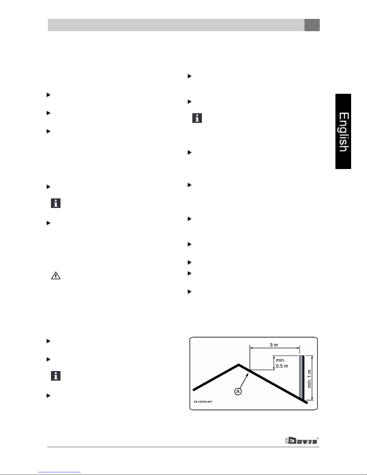
The chimney must be at least 4 metres high.
As a rule of thumb: 60 cm above the ridge of the
roof.
If the ridge of the roof is morethan3 metres away
from the flue: stick to the measurements in the
following figure. A = the highest point of the roof
within a distance of 3 metres.
Installation requirements
Subjectto change because of technicalimprovements
5
Page 7
Installation requirements
Ventilation of the area
For good combustion, the appliance needs air
(oxygen). That air is suppliedvia adjustable air inlets
from the area where the appliance is installed.
The combustion will beincomplete in case of
insufficient ventilation, which results in toxic
gases being producedand spread through the
area.
As a rule of thumb, the air supply should be
5.5cm²/kW. Extra ventilation is needed when:
The appliance is in an area that is well insulated.
There is mechanical ventilation, for example a
central extraction system or anextraction hood in
an open kitchen.
You can provide extra ventilation by having a
ventilation louvre installed in the outside wall.
Make sure that otherair consumingappliances (such
as tumble-driers, other heating appliances or a bath
room fan) have theirown supply of outside air, or are
switched off when you use the appliance.
You can also connect the appliance to a supply
of outside air. Forthis purpose, a connecting
kit has been included. Extra ventilation is not
needed in that case.
Floor and walls
The floor on which the appliance is placed must have
sufficient load bearing capacity. For the appliance
weight: see the appendix "Technical Data".
Protect a flammablefloorfrom heat radiation
by means of a fireproof protective plate. See
the appendix "Distance from combustible
material".
Keep enough distance between the appliance
andcombustible materials such as wooden
walls and furniture.
The connecting tube radiates heat too. Ensure
that there is sufficient distance or a shield
between the connecting tube and combustible
material.
The rule of thumb for a single-walled tube is a
distance of 3x the diameter. If a lining shell is
fitted around the tube, a distance of 1x the
diameter is permissible.
Carpets and rugs must be at least 80 cm away
from the fire.
Protect a flammablefloorfrom possible falling
ash in front of the fire with the aid of a fireproof
protective plate. Theprotective plate must
comply with national standards.
For further requirements with respect to fire
safety, see the appendix "Distance from
combustible material".
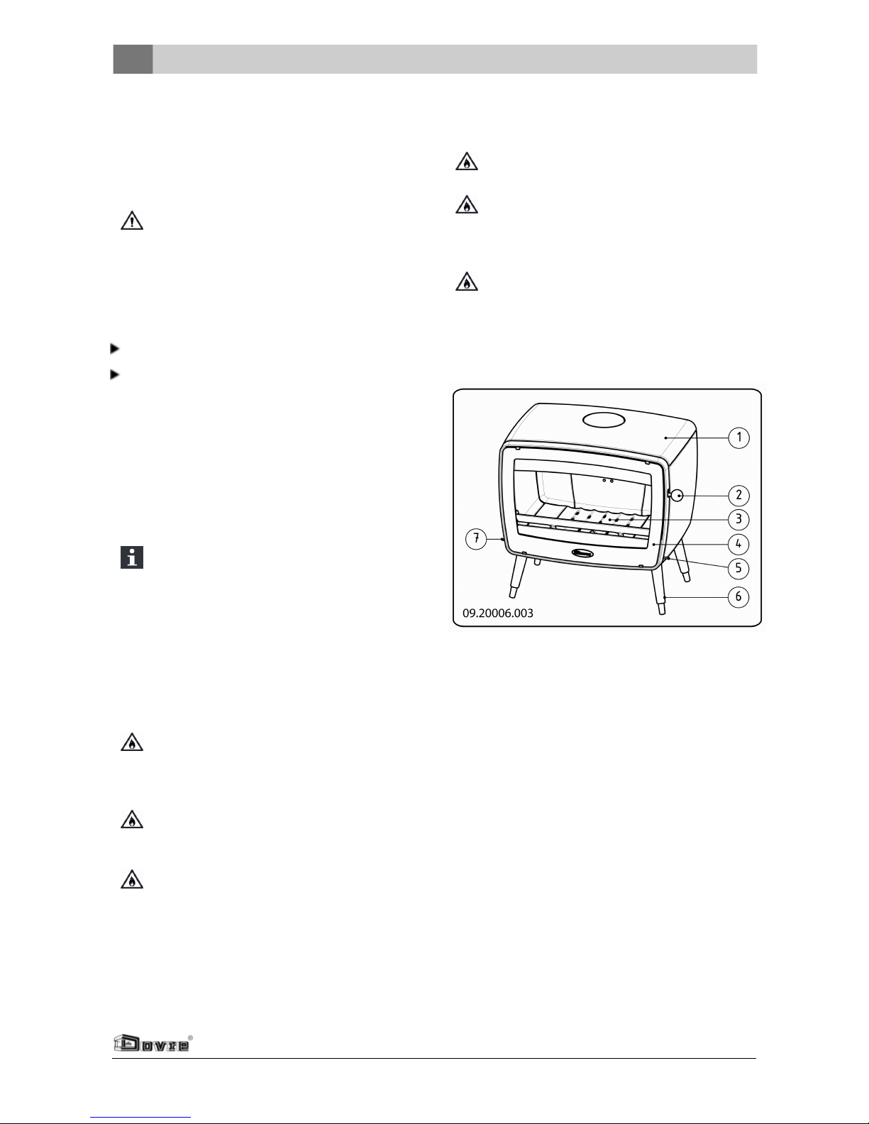
Product description
1. Top plate
2. Latch button
3. Bottom of the fire compartment
4. Door
5. Secondary air slide
6. Leg
7. Primary air slide
6
Subjectto change because of technicalimprovements
Page 8
Installation
General preparation
Please check the appliance for damage caused
during transport or any other damage or defects
immediately after delivery. The appliance is
attached to the pallet with screws at the bottom.
If you detect damage causedduringtransport
or any other damage ordefects, do not use the
appliance and notify the supplier.
Remove the removableparts (fire-resistant inner
plates, fire grate, top plate, ashtray) from the
appliance before you start installing the appliance.
By removing removable parts, it is easier to
move the appliance and to avoid damage.
Note the location of those removable parts, so
that you have nodifficulties in installingthe
parts in the right place later on. The appliance
is attached to the pallet with screws at the
bottom.
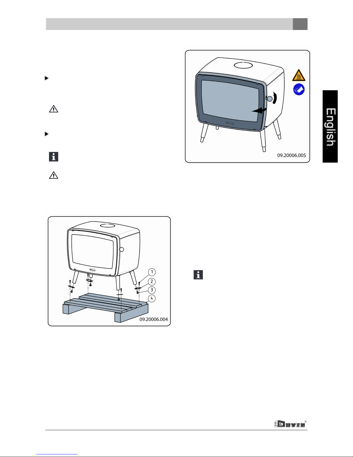
1. Openthe door; see the following figure.
2. Remove the fire-resistant inner plates; see the
following figure.
The following tips may helpin the removal of the
inner plates:
a. Lift baffle plate 3 on the front and pull it
forwards by 2 cm.
b. Now, lift the baffle plate on the left-hand side
andremove the left-hand inner plate 1 first.
c. Then remove baffle plate 3 followed by inner
plates 7, 8, 9, 2 etc.
Vermiculite inner plates are light andtend
to be ochrous in colour when delivered.
They insulate the combustion chamber to
boost combustion. Cast iron inner plates
protect the combustion chamber and
dissipate heat to the environment.
Installation
Subjectto change because of technicalimprovements
7
Page 9
Installation
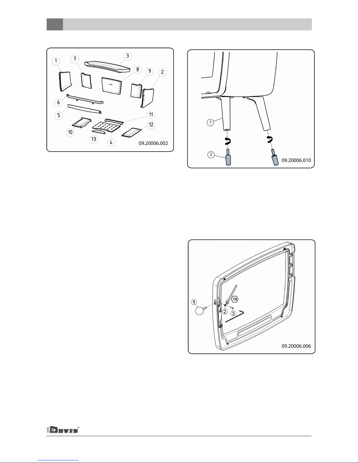
Removable internal sections
1 left-hand side inner plate
2 right-hand side inner plate
3 baffle plate
4
centre bottom of the fire
compartment
5 bottom fire basket not for Vintage 30
6 top fire basket
7 left-hand rear inner plate not for Vintage 30
8 centre rear inner plate not for Vintage 30
9 right-hand rear inner plate not for Vintage 30
10
left-hand bottom of the fire
compartment
not for Vintage 30
11
rear bottom of the fire
compartment
not for Vintage 30
12
right-hand bottom of the
fire compartment
not for Vintage 30
13 ash removal port not for Vintage 30
3. Remove the ashtray.
Please note:the Vintage 30 does not have an
ashtray.
4. Install the adjustable feet under the legs, see
figure. When used on a slippery floor surface, it is
recommended that a rubber mat is used under the
legs.
Door lock
The appliance is supplied with the latch button
installed. You coulddecide to use the latch button as
a "cold hand".
1. Loosennut (2) slightly and loosen the set screw
(3)until the latch button is released.
2. Re-tighten nut (2).
3. Install the latch retainer on the base, see figure.
8
Subjectto change because of technicalimprovements
Page 10
4. Place the latch button into the latch retainer, see
figure.
Preparing the connection to
chimney
When connecting the appliance to a chimney, you can
choose the top or rear of the appliance.
When the appliance is delivered, the
connection on the rear is left open.
Plug the outlet that you don't want to use with the
corresponding cover that was supplied.
Install the corresponding connection collar that
was supplied on the outlet that you want to use.
Sealant and materials are supplied.
Connecting to the rear
1. Apply supplied fibre glass sealing tape of 10x3mm
to the contact surface of the connection collar.
2. Install the connection collar to the back wall with
the materials.
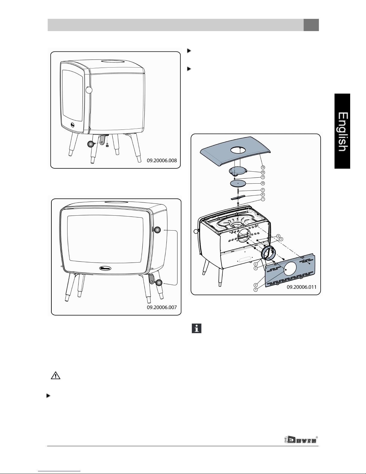
Connect to top
1. Remove the top plate.
The top plate can be taken off the appliance
just like that.
2. Remove the decorative cover (12) from the top
plate.
3. Remove the cover (10) from the inner top plate.
4. Apply sealing tapemeasuring 10 x 3mm to the
contact surface of the connection collar.
5. Install the connection collar to the inner top plate
with the materials.
Installation
Subjectto change because of technicalimprovements
9
Page 11

Installation
6. Install the cover to the back wall with the
materials.
Preparing the connection to
the outside air
If the appliance is installed in a room without sufficient
ventilation, you can install the connecting kit on the
appliance (supplied with the appliance) for the supply
of outside air. Some of the airinlets on the appliance
must then be plugged with the blanking material
provided.
The air supply tube has a diameter of 100mm. If the
tube is smooth, it may be nolongerthan 12m. If
accessories such as bends are used, the maximum
length (12m)must be reducedby 1m for each
accessory used.
Outside air connection via the floor
1. Make an openingin the floor(see Appendix 2,
Measurements, for the correct position of the
opening).
2. Hermetically close the air supply tubeat the floor.
3. Install the connection collar on the bottom plate
andclose the rear wall with the cover.
The guardis no 3 on the diagram.
Connection to outside air via the
rear of the appliance:
1. Make an openingin the wall (see Appendix 2,
Measurements, for the correct position of the
opening).
2. Hermetically close the air connection tubeat the
wall.
3. Install the connection collar on the back wall and
close the opening in the bottom plate with the
cover.
The guardis no 4 on the diagram.
10
Subjectto change because of technicalimprovements
Page 12

Install and connect
1. Install the appliance in the right place, and make
sure it is level.
2. Connect the appliance hermetically to the flue.
3. In the case of connection to outside air: attach the
connection to the outside air to the connecting set
that you have attached to the appliance.
4. Install all the parts you had removed in the right
places in the appliance.
Never use the appliance without the fireresistant inner plates.
The appliance is now ready for use.
Installation
Subjectto change because of technicalimprovements
11
Page 13

Use
Use
First use
When you use the appliance for the first time, make
an intense fire and keep it going for a good few hours.
This will cure the heat-resistant paint finish. This may
result in some smoke andodours. You couldopen
windows and doors for a while in the area where the
appliance is located.
Fuel
This appliance is only suitablefor the burning of
natural wood; sawn and chopped woodthat is
sufficiently dry.
Do not use otherfuels, as they can lead to serious
damage to the appliance.
You are not allowed to use the following fuels, as they
pollute the environment, and because they heavily
pollute the appliance and flue, which may lead to a
chimney fire:
Treated wood, such as scrapwood, painted wood,
impregnated wood, preserved wood, plywoodand
chipboard.
Plastics, scrap paperand domestic waste.
Wood
Hardwood, such as from oaks, beeches, birches
andfruit trees, is the ideal fuel for your stove. This
type of wood burns slowly with calm flames.
Softwood contains more resins, burns faster and
gives off more sparks.
Use dried woodthat contains no more than 20%
moisture. The wood must have dried for at least 2
years.
Saw the wood to size andsplit it when it is still
fresh. Fresh wood is easier to split, and split wood
dries more easily. Storethe woodunder a roof
wherethe wind has wind freeaccess.
Do not use damp wood. Damp logs do not produce
heat as all of the energy is used in the evaporation
of the moisture. This will result in a lot of smoke
andsoot deposits onthe door of the appliance and
in the chimney. The water vapour will condense in
the appliance and can leak away through chinks in
the appliance, causing black stains on the floor. It
may also condense in the chimney andform
creosote. Creosote is a highly flammable
compound and may cause a chimney fire.
Lighting
You can check whetherthe flue has enough draught
by lighting a ball of paperabove the baffle plate. A cold
flue often does not have enough draught and
consequently, some smoke may escapeinto the room
instead of up the chimney. By lighting the fire in the
way described here, you can avoid this problem.
1. Stack two layers of medium sized logs crosswise.
2. Stack two layers of kindling crosswise on top of
the logs.
3. Place a firelightercubein the lowerlayer of
kindlingand light the cube according to the
instructions on the packaging.
4. Close the door of the appliance and open the
primary air inlet and the secondary air inlet of the
appliance; see the following figure.
5. Let this fire develop into a good blaze until there is
glowingbed of charcoal. You can thenadd fuel
andadjust the appliance, see the chapter on
burning wood.
12
Subjectto change because of technicalimprovements
Page 14

Primary air slide
Secondary air slide
Burning wood
After you have followed the instructions for lighting :
1. Slowly open the door of the appliance.
2. Spread out the charcoal bed evenly across the
bottom of the fire compartment.
3. Stack a few logs on the charcoal bed.
Open stacking
If the logs are stacked openly, the wood will burn
quickly as the oxygen can reach each log easily. If
you want to use the stove for a short while, make an
open stack.
Compact stacking
If the logs are stacked tightly, the wood will burnmore
slowly as the oxygen can only reach some logs
Use
Subjectto change because of technicalimprovements
13
Page 15

Use
easily. If you want to burn wood for a longer period,
make a compact stack.
3. Close the door of the appliance.
4. Close the primary air inlet and leave the secondary
air inlet open.
Fill the appliance up to onethird capacity.
Controlling the air
The appliance has various features for the air control
(see figure).
The primary air slide controls the airflow under the
grille (1).
The secondary air slide controls the air flow for the
glass and the vents in the back wall (2).
The baffle plate has permanent vents (3) that allow for
post-combustion.
Advice
Never burn wood with an open door.
Regularly burnwood with intense roaringfires.
If you frequently have low intensity fires, tar
andcreosote may be deposited in the chimney
. Tar and creosote are highly combustible
substances. Thicker layers of these
substances might catch fire when the
temperature in the chimney increases
suddenly and steeply. Thereforeit is
necessary for the fire to regularly burn very
intensely, so that layers of tar and creosote
disappear.
Low intensity fires also cause tar deposits on
the stove window and door.
When the outside temperatureis not very low,
it is better to burn wood intensely for a few
hours instead of having a low intensity fire for a
longperiodof time.
Control the air supply with the secondary air inlet.
The secondary air inlet not only supplies air to
the fire but to the glass as well, so that it does
not get dirty so quickly.
Open the primary air inlet for the time being if the air
supply by the secondary air inlet is inadequate orif
you want to fan the fire.
It is better to add a small amount of logs regularly
than to add many logs at the same time.
Extinguishing the fire
Do not add fuel and just let the fire go out. If a fire is
damped down by reducingthe supply of air, harmful
substances will be produced and released. Therefore,
let the fire go out naturally. Keep aneye on the fire
until it is gone out. If the fire has diedcompletely, all
air inlets can be closed.
Removing ashes
After the wood has been burnt, a relatively small
amount of ashes is left over. This bed of ashes is a
good insulatinglayer for the bottom of the fire
compartment andimproves combustion. Therefore,
you can leave a thin layer of ashes on the bottom of
the fire compartment.
However, the air supply through the bottom of the fire
compartment must not be impeded and no ash should
be allowed to accumulate behind a cast iron inner
plate. Therefore, remove any excess ash frequently.
14
Subjectto change because of technicalimprovements
Page 16

1. Openthe door of the appliance.
2. Use the scraper to open the ash removal port in
the bottom of the fire compartment (1).
3. Using the scraper, sweep the excess ash (2)
through the ash removal port into the ashtray
underneath.
4. Close the ash removal port.
5. Remove the ashtray (3) using the glove provided
andempty the ashtray.
6. Install the ashtray and close the appliance door.
Comment: The Vintage30 has no ashtray. Remove
the ash with the aid of a spoon oruse an "ash clean
system" on the vacuum cleaner.
Fog and mist
Fog and mist hinder the ventingof smoke gases
through the flue. Smoke can precipitate andcause a
stench. If it is not strictly necessary, it is better not to
use the stove with fog andmist.
problems
Refer to the appendix "Diagnostic diagram" to
solve any problems in using the appliance.
If the appliance does not give off enough heat:
Refer to the appendix "Diagnostic diagram" and
also check whether you are burning enough fuel.
Use
Subjectto change because of technicalimprovements
15
Page 17

Maintenance
Maintenance
Follow the maintenance instructions in this chapter to
keep the appliance in good condition.
Chimney
In many countries, people are legally required to have
their chimney checked and maintained.
At the beginning of the heating season: have the
chimney swept by an expert.
Duringthe heating season and after the chimney
has not been used for a long time: have the
chimney checked for soot deposits.
After the heating season: seal off the chimney with
a ball of paper.
Cleaning and other regular
maintenance activities
Do not clean the appliance when it is still
warm.
Clean the exterior of the appliance with a dry lintfree cloth.
At the end of the heatingseason, you can cleanthe
interior of the appliance thoroughly:
If necessary, first remove the fire-resistant inner
plates. See the chapter "Installation" for
instructions on removing and installing the inner
plates.
If necessary, cleanthe airsupply channels.
Remove the top plate to this end. The top plate lies
loosely on the appliance.
If required, remove the baffle plate at the top of the
appliance and clean it.
Checking fire-resistant inner plates
The fire-resistant inner plates are consumables and
subject to wear . Check the fire-resistant inner plates
frequently and replace them whennecessary.
See the chapter "Installation" for instructions on
removing andinstalling the inner plates.
The insulating vermiculite inner plates may
develop hairline cracks, but that does not
affect their performance adversely.
Cast-iron inner plates go a long way if you
frequently remove the ash that may pile up
behind it. If accumulated ash behind a cast-iron
plate is not removed, the plate cannot dissipate
the heat anymore to its surroundings andthat
may cause the plate to warp or crack.
Never use the appliance without the fireresistant inner plates.
Cleaning glass
Dirt clings less easily to well cleanedglass. Proceed
as follows:
1. Remove dust and loose soot with a moist cloth.
2. Clean the glass with stove window cleaner:
a. Apply stove window cleaner to a kitchen
sponge, rub down the entire glass surface and
expose it to the cleaningagent.
b. Remove the dirt with a moist cloth or kitchen
tissue.
3. Clean the glass again with a normal glass cleaning
product.
4. Rub the glass cleanwith a dry cloth or kitchen
tissue.
Do not use abrasive or aggressive products to
clean the glass.
Wear household gloves to protect your hands.
If the glass in the appliance is broken or
cracked, it must be replacedbefore you can
use the appliance again.
Make sure that no stove window cleaner runs
between the glass and the cast-iron door.
Maintaining enamelled fire
Never clean the appliance whenit is still hot. The
enamelled surface of the fire can becleaned most
effectively with a mild green soap and lukewarm
water. Use as little water as possible, rubthe surface
dry andprevent the formation of rust. Wire wool or
otherabrasives should never be used. Never place a
kettle directly onto an enamelledfire; use a stand and
prevent damage from occurring.
16
Subjectto change because of technicalimprovements
Page 18

Lubrication
Although cast-iron is slight self-lubricating, you will
still have to lubricate moving parts frequently.
Lubricate the moving parts (such as hinge pins,
latches and air slides) with heat resistant grease
that is available in the specialist trade.
Re-adjusting the door lock
1. Loosenthe hexagon nut (1)slightly.
2. Screw the locking cam (2) in or out with the help of
a screwdriver.
3. Re-tighten the locking nut.
Readjusting the hinge
1. Loosenthe screws (2) and (3)slightly.
2. Screw setscrew (1) in if the doormust be raised
andout if the door must be lowered.
3. Retighten the screws (2) and (3) firmly.
Removing the glass pane
1. Loosenthe 2xM5 nuts on the top only.
2. Tilt the pane forwards and lift the pane out of the
bottom fixing lips.
Beforereplacing:
1. Place the glass pane together with the two glass
fixings.
2. Tighten the 2xM5 nuts.
Maintenance
Subjectto change because of technicalimprovements
17
Page 19

Maintenance
Touching up the finish
Small areas of damaged paint finish can be touched
up with a spraying can of special heat-resistant paint
finish availablefrom your supplier.
Areas of damagedenamel can betouched up with a
special heat-resistant paint finish that is available
from your supplier.
Checking the seal
Check whether the sealing ropeof the door is still
in good conditionand works well. The sealing rope
is subject to wear and needs to be replacedin time.
Check the appliance for air leaks. Close any
chinks with stove sealant.
Let the sealant harden fully beforeyou start a
fire in the appliance, because otherwise any
moisture in the sealant will evaporate in
bubbles and cause a new air leak.
Vintage 50 spare parts
Pos. Description Description Quantity
1 03.77393.000 left-hand side inner
plate
1
2 03.77394.000 right-hand side inner
plate
1
3 03.77395.000 baffle plate 1
4 03.66534.000 centre bottom of the fire
compartment
1
5 03.77405.000 bottom fire basket 1
6 03.77406.000 top fire basket 1
7 03.77396.000 left-hand rear inner plate 1
8 03.77392.000 centre rear inner plate 1
9 03.77397.000 right-hand rear inner
plate
1
10 03.56328.000 left-hand bottom of the
fire compartment
1
11 03.56329.000 rear bottom of the fire
compartment
1
12 03.56327.000 right-hand bottom of the
fire compartment
1
13 03.05407.000 ash removal port 1
18
Subjectto change because of technicalimprovements
Page 20

Vintage 35 spare parts
Pos. Description Description Quantity
1 03.77393.000 Left-hand side inner plate 1
2 03.77394.000 right-hand side inner
plate
1
3 03.77500.000 baffle plate 1
4 03.66534.000 centre bottom of the fire
compartment
1
5 03.77410.000 bottom fire basket 1
6 03.77408.000 top fire basket 1
7 03.77501.000 left-hand rear inner plate 1
8 03.77399.000 centre rearinner plate 1
9 03.77502.000 right-hand rear inner plate 1
10 03.56330.000 left-hand bottom of the
fire compartment
1
11 03.56329.000 rear bottom of the fire
compartment
1
12 03.56331.000 right-handbottom of the
fire compartment
1
13 03.05407.000 ash removal port 1
Vintage 30 spare parts
Pos. Description Description Quantity
1 03.77393.000 Left-hand side inner
plate
1
2 03.77394.000 right-handside inner
plate
1
3 03.77398.000 baffle plate 1
4 03.66535.000 bottom of the fire
compartment
1
5 03.77409.000 bottom fire basket 1
6 03.77407.000 top fire basket 1
Maintenance
Subjectto change because of technicalimprovements
19
Page 21

Appendix 1: Technical data
Appendix 1: Technical data
Model Vintage 50 Vintage 35 Vintage 30
Nominal output 9 kW 7 kW 5 kW
Flue connection (diameter) 150mm 150mm 150 mm
Weight +/- 155 kg +/- 125 kg +/- 95 kg
Recommended fuel Wood Wood Wood
Fuel property, max. length 50 cm 35 cm 30 cm
Mass flow of flue gases 6.4 g/s 4.9 g/s 4.2 g/s
Flue gas temperature measured in the
measurement section
232 251 244
Temperature measured downstream from the flue
spigot
328 298 305
Minimum draught 12 Pa 12 Pa 12 Pa
CO emission (13%O2) 0,10 % 0,05 % 0,05 %
NOx emission (13% O2) 112mg/Nm³ 84 mg/Nm³ 127 mg/Nm³
CnHm emission (13%O2) 96 mg/Nm³ 82 mg/Nm³ 48 mg/Nm³
Particulate emission 27.1 mg/Nm³
16.4
mg/Nm³
6.0 mg/Nm³
Particulate emission in accordance with NS3058NS3059
4.94 gr/kg 4,99 gr/kg 1.38 gr/kg
Efficiency 84,2 % 83 % 80,4 %
20
Subjectto change because of technicalimprovements
Page 22

Appendix 2: Measurements
Vintage 50
Appendix 2: Measurements
Subjectto change because of technicalimprovements
21
Page 23

Appendix 2: Measurements
Vintage 35
22
Subjectto change because of technicalimprovements
Page 24

Vintage 30
Appendix 2: Measurements
Subjectto change because of technicalimprovements
23
Page 25

Appendix 3: Distance from combustible material
Appendix 3: Distance from combustible material
Vintage 50 - Minimum distances for versions without heat shield:
1. Combustible material
2. Incombustible material, thickness 100mm
Vintage 50 - Minimum distances for versions with heat shield:
Comment: heat shield is available as an option.
1. Combustible material
2. Incombustible material, thickness 100mm
24
Subjectto change because of technicalimprovements
Page 26

Vintage 35 - Minimum distances for versions without heat shield:
1. Combustible material
2. Incombustible material, thickness 100mm
Vintage 35 - Minimum distances for versions with heat shield:
Comment: heat shield is available as an option.
1. Combustible material
2. Incombustible material, thickness 100mm
Appendix 3: Distance from combustible material
Subjectto change because of technicalimprovements
25
Page 27

Appendix 3: Distance from combustible material
Vintage 30 - Minimum distances for versions without heat shield:
1. Combustible material
2. Incombustible material, thickness 100mm
Vintage 30 - Minimum distances for versions with heat shield:
Comment: heat shield is available as an option.
1. Combustible material
2. Incombustible material, thickness 100mm
26
Subjectto change because of technicalimprovements
Page 28

Appendix 4: Diagnostic diagram
Problem
Wood does not keep burning
Gives off insufficient heat
Smoke emissions into the room when adding wood
Fire in appliance is too intense, is hard to adjust
Deposit on the glass
possible cause possible solution
Insufficient draught
A cold flue usuallyfailsto create sufficient draught. Follow the
instructionsfor lightingin the "Usage" chapter; open a window.
Wood too damp Use wood with no more than 20% moisture.
Piecesof wood too big
Use small pieces of kindling.Use split logsno larger than 30 cmin
circumference.
Wood stacked up incorrectly
Stackup the wood in a way that allows an adequate air flow between
the logs(open stacking, see "Burning wood")
Chimney does not work properly
Check whether the chimneymeets the requirements: at least 4
metres high, right diameter, wellinsulated, smooth inside,not too
many bends, no obstructions in chimney(bird's nest, too much soot
deposit), hermetically tight (no chinks)
Chimney stack incorrect Sufficiently high above the roof, no obstacles in itsvicinity
Air inlets setincorrectly Openthe air inlets completely.
Applianceconnected to chimney
incorrectly
Connection should be hermeticallytight.
Vacuum in area where appliance is
installed
Switch off extraction systems.
Insufficient supplyof fresh air
Provide an adequate air supply,if necessary useconnection to
outside air.
Adverse weather conditions?
Inversion (reversed air flow in chimney
because of a high outside temperature),
extreme wind velocities
We recommend youdon't use the appliance in the case of inversion.
Installan extra hood on the flue to increase the draught if need be.
Draught inthe living room
Avoiddraught inthe living room, do not place the appliance near a
door, or heating air channels.
Flames touchthe glass
Make sure the wood doesnot lietoo close to the glass. Slide the
primary air inlet cover closer to the "Closed" position.
Applianceisleaking air Check the door seals and the device chinks.
Appendix 4: Diagnostic diagram
Subjectto change because of technicalimprovements
27
Page 29

Index
Index
A
Adding fuel 14
Adding wood
smoke emissions into the room 27
Air control 14
Air inlets 12
Air leak 18
Air supply for fire 14
Ash removal port 15
Ashes
remove 14
Ashtray
open 15
B
Burning wood 13
addfuel 14
adding logs 13
appliance is hardto adjust 27
fire is too intense 27
insufficient heat 15, 27
C
Carpet 6
Cast iron inner plates 7
Chimney
height 5
prepare connection 9
sweep 16
Chinks in appliance 18
Clean
glass 16
Cleaning
appliance 16
Combustible material
distance from 24
Connection
measurements 21
Connection collar for connection to chimney 9
Connection to chimney 9
at top 9
top 9
Connection to supply of outside air 10
Control air supply 14
Control of air 14
Cover on flue 5
Creosote 14
D
Damage 7
Damp wood 12
Door
open 7
sealingrope 18
Draught 20
Drying of wood 12
E
Efficiency 20
F
Filling height 14
Fire
extinguishing 14
lighting 12
Fire going out 14
Fire safety
distance from combustible material 24
floor 6
furniture 6
walls 6
Fire-resistant inner plates
maintenance 16
remove 7
warning 11
Floors
fire safety 6
loadbearing capacity 6
Flue
connection diameter 20
connection to 11
maintenance 16
requirements 5
Flue gas
mass flow 20
28
Subjectto change because of technicalimprovements
Page 30

Subjectto change because of technicalimprovements
29
Index
temperature 20
Fog, do not burn wood 15
Foot
cover 10
Fuel
adding 14
adding wood 14
necessary amount 15
suitable 12
unsuitable 12
G
Glass
clean 16
deposit 27
H
Heat
insufficient 27
Heat, insufficient 15
Hood onthe flue 5
I
Innerplates, fire-resistant
remove 7
Installation
measurements 21
K
Kindled fire 12
Kindling 27
L
Lighting 12
Load bearing capacity of floor 6
Lubricant 17
Lubricate 17
M
Maintenance
chimney 16
clean glass 16
cleaning the appliance 16
fire-resistant inner plates 16
lubrication 17
seal 18
Measurements 21
Mist, do not burn wood 15
N
Nominal output 15, 20
O
Open
ash removal port 15
ashtray 15
door 7
P
Paint finish 12
Particulate emission 20
Parts, removable 7
Prevent a chimney fire 14
Primary air inlet 12
R
Removable parts 7
Removal of ashes 14
Remove
fire-resistant inner plates 7
Remove ashes 14
S
Scraper for ash removal 15
Screens
clean 16
deposit 27
Sealing ropefor door 18
Secondary air inlet 12
Smoke
on first use 12
Smoke emissions into the room 5, 27
Softwood 12
Solving problems 15, 27
Page 31

Index
Stacking logs 13
Storingwood 12
Stove window cleaner 16
Suitable fuel 12
Supply of outside air 6, 10
connection to 11
Sweep chimney 16
T
Tar 14
Temperature 20
U
Unsuitable fuel 12
V
Ventilation 6
connect supply of outside air 10
ruleof thumb 6
Ventilationlouvre 6
Vermiculite inner plates 7
W
Walls
fire safety 6
Warning
chimney fire 4, 12, 14
combustible materials 4
fire-resistant inner plates 11
glass broken or cracked 4, 16
hot surface 4
regulations 4
stove window cleaner 16
terms and conditions for insurance 5
ventilation 4, 6
Weatherconditions, do not burn wood 15
Weight 20
Wood 12
damp 12
does not keepburning 27
drying 12
right sort 12
storing 12
30
Subjectto change because of technicalimprovements
Page 32

 Loading...