

Dovre Sense 100, Sense 103, Sense 203, Sense 300, Sense 303 Installation Instructions And Operating Manual
...Page 1
INSTALLATIEVOORSCHRIFTEN EN GEBRUIKSAANWIJZING
HOUTKACHEL
INSTALLATION INSTRUCTIONS AND OPERATING MANUAL
WOOD STOVE
INSTALLATION ET MODE D’EMPLOI
POELE A BOIS
EINBAUANLEITUNG UND GEBRAUCHSANWEISUNG
HOLZ-FEUERSTÄTTE
INSTRUCCIONES DE INSTALACIÓN Y USO
ESTUFA DE LEÑA
ISTRUZIONI PER L'INSTALLAZIONE E L'USO
STUFA A LEGNA
MONTERINGS- OG BRUKSANVISNING
ILDSTED
Sense 100 Sense 103 Sense 200 Sense 203
Sense 300 Sense 303 Sense 400 Sense 403
Sense
03.27127.100 - 09-2014
Page 2
2
Wijzigingen op grond van technische verbeteringen voorbehouden
Inhoudsopgave
Inleiding 3
Prestatieverklaring 4
Prestatieverklaring 6
Prestatieverklaring 8
Veiligheid 10
Installatiecondities 10
Algemeen 10
Schoorsteen 10
Ventilatie van deruimte 11
Vloer en wanden 11
Productbeschrijving 12
Installatie 13
Algemene voorbereiding 13
Schoorsteenaansluitingvoorbereiden 14
Buitenluchtaansluiting voorbereiden 15
Plaatsen enaansluiten 15
Gebruik 16
Eerste gebruik 16
Brandstof 16
Aanmaken 16
Stoken met hout 17
Regeling verbrandingslucht 18
Doven van het vuur 19
Ontassen 19
Nevel en mist 19
Eventueleproblemen 19
Onderhoud 19
Schoorsteen 20
Schoonmaken en ander regelmatig onderhoud 20
Wisselstukken Sense 22
Bijlage 1: Technische gegevens 24
Bijlage 2: Afmetingen 25
Bijlage 3: Afstand tot brandbaar materiaal 33
Bijlage 4: Diagnoseschema 38
Index 39
Page 3
Wijzigingen op grond van technische verbeteringen voorbehouden
3
Inleiding
Geachte gebruiker,
Met de aankoopvan dit verwarmingstoestel van
DOVRE heeft u gekozen vooreen kwaliteitsproduct.
Dit product maakt deel uit van een nieuwe generatie
energiezuinige en milieuvriendelijke
verwarmingstoestellen. Deze toestellenmaken
optimaal gebruik van zowel convectiewarmte als
stralingswarmte.
Uw DOVRE toestel is geproduceerdmet de
modernste productiemiddelen. Mocht er
onverhoopt toch iets mankerenaan uw toestel, dan
kunt u altijd een beroep doen opde DOVRE
service.
Het toestel mag niet gewijzigd worden; gebruik
steeds originele onderdelen.
Het toestel is bedoeld voorplaatsing in een
woonruimte. Het moet hermetisch worden
aangesloten op een goed werkende schoorsteen.
Wij adviseren u het toestel te laten installeren door
eenbevoegd installateur.
DOVRE kan niet aansprakelijk wordengesteld
voor problemenof schadedoor een onjuiste
installatie.
Bij installatie en gebruik moeten de hierna
beschreven veiligheidsvoorschriften in acht
worden genomen.
In deze handleiding leest u hoe u het DOVRE
verwarmingstoestel op een veilige manier installeert,
gebruikt en onderhoudt. Als u aanvullende informatie
of technische gegevens wilt of eeninstallatieprobleem heeft, neemt u dan eerst contact op met uw
leverancier.
© 2014 DOVRE NV
Page 4

Prestatieverklaring
Volgens de bouwproductenverordening 305/2011
Nr. 033-CPR-2013
1. Unieke identificatiecode van het producttype:
Sense 100 - 200/ 4,9 kW
2. Type-, partij- of serienummer, dan wel een ander identificatiemiddel voor het bouwproduct, zoals
voorgeschreven in artikel 11, lid 4:
Uniek serienummer.
3. Beoogde gebruiken van het bouwproduct, overeenkomstig de toepasselijke geharmoniseerde
technische specificatie, zoals door de fabrikant bepaald:
Kachel voorvaste brandstof zonder productie van warm water volgens EN 13240.
4. Naam, geregistreerde handelsnaam of geregistreerd handelsmerk en contactadres van de fabrikant,
zoals voorgeschreven in artikel 11, lid 5:
Dovre N.V. Nijverheidsstraat 18 2381 WeeldeBelgium.
5. Indien van toepassing, naam en contactadres van de gemachtigde wiens mandaat de in artikel 12,
lid 2, vermelde taken bestrijkt:
-
6. Het systeem of de systemen voor de beoordeling en verificatie van de prestatiebestendigheid van
bouwproduct, vermeld in bijlage V:
Systeem 3
7. Indien de prestatieverklaring betrekking heeft op een bouwproduct dat onder een geharmoniseerde
norm valt:
De aangestelde instantie KVBG, geregistreerd onder het nummer 2013, heeft ondersysteem 3 een type-keur
uitgevoerd en heeft het testrapport nr H20130113 verstrekt.
8. Indien de prestatieverklaring betrekking heeft op een bouwproduct waarvoor een Europese
technische beoordeling is afgegeven:
-
4
Wijzigingen op grond van technische verbeteringen voorbehouden
Page 5

Wijzigingen op grond van technische verbeteringen voorbehouden
5
9. Aangegeven prestatie:
De geharmoniseerde norm EN 13240:2001/A2 ;2004/AC :2007
Essentiële karakteristieken Prestaties Hout
Brandveiligheid
Vuurbestendigheid A1
Afstandtot brandbaarmateriaal
Minimaleafstand in mm
Achterkant: 300
Zijkant: 500
Risico van uitvallende gloeiende deeltjes Conform
Emissie van verbrandingsproducten CO: 0,18% (13%O2)
Oppervlaktetemperatuur Conform
Elektrische veiligheid -
Gemakkelijk te reinigen Conform
Maximale werkingsdruk -
Rookgastemperatuurbij nominaal vermogen 247°C
Mechanische weerstand (gewicht dragen van
schoorsteen)
Niet bepaald
Nominaal vermogen 4,9 kW
Rendement 79,5 %
10. De prestaties van het in de punten 1 en 2 omschreven product zijn conform de in punt 9
aangegeven prestaties.
Deze prestatieverklaring wordt verstrekt onder de exclusieve verantwoordelijkheid van de in punt 4
vermelde fabrikant:
01/10/2013 Weelde
Tom Gehem
CEO
In het kader van een continueproductverbetering, kunnen specificaties van het geleverde toestel afwijken van de
beschrijving in deze brochure, zonder voorafgaandekennisgeving.
DOVRE N.V.
Nijverheidsstraat 18 Tel : +32 (0) 1465 91 91
B-2381 Weelde Fax : +32 (0) 14 6590 09
België E-mail : info@dovre.be
Page 6

Prestatieverklaring
Volgens de bouwproductenverordening 305/2011
Nr. 032-CPR-2013
1. Unieke identificatiecode van het producttype:
Sense 100 - 200/ 7 kW
2. Type-, partij- of serienummer, dan wel een ander identificatiemiddel voor het bouwproduct, zoals
voorgeschreven in artikel 11, lid 4:
Uniek serienummer.
3. Beoogde gebruiken van het bouwproduct, overeenkomstig de toepasselijke geharmoniseerde
technische specificatie, zoals door de fabrikant bepaald:
Kachel voorvaste brandstof zonder productie van warm water volgens EN 13240.
4. Naam, geregistreerde handelsnaam of geregistreerd handelsmerk en contactadres van de fabrikant,
zoals voorgeschreven in artikel 11, lid 5:
Dovre N.V. Nijverheidsstraat 18 2381 WeeldeBelgium.
5. Indien van toepassing, naam en contactadres van de gemachtigde wiens mandaat de in artikel 12,
lid 2, vermelde taken bestrijkt:
-
6. Het systeem of de systemen voor de beoordeling en verificatie van de prestatiebestendigheid van
bouwproduct, vermeld in bijlage V:
Systeem 3
7. Indien de prestatieverklaring betrekking heeft op een bouwproduct dat onder een geharmoniseerde
norm valt:
De aangestelde instantie KVBG, geregistreerd onder het nummer 2013, heeft ondersysteem 3 een type-keur
uitgevoerd en heeft het testrapport nr H20130112 verstrekt.
8. Indien de prestatieverklaring betrekking heeft op een bouwproduct waarvoor een Europese
technische beoordeling is afgegeven:
-
6
Wijzigingen op grond van technische verbeteringen voorbehouden
Page 7
Wijzigingen op grond van technische verbeteringen voorbehouden
7
9. Aangegeven prestatie:
De geharmoniseerde norm EN 13240:2001/A2 ;2004/AC :2007
Essentiële karakteristieken Prestaties Hout
Brandveiligheid
Vuurbestendigheid A1
Afstandtot brandbaarmateriaal
Minimaleafstand in mm
Achterkant: 300
Zijkant: 500
Risico van uitvallende gloeiende deeltjes Conform
Emissie van verbrandingsproducten CO: 0,07% (13%O2)
Oppervlaktetemperatuur Conform
Elektrische veiligheid -
Gemakkelijk te reinigen Conform
Maximale werkingsdruk -
Rookgastemperatuurbij nominaal vermogen 274°C
Mechanische weerstand (gewicht dragen van
schoorsteen)
Niet bepaald
Nominaal vermogen 7 kW
Rendement 80,0 %
10. De prestaties van het in de punten 1 en 2 omschreven product zijn conform de in punt 9
aangegeven prestaties.
Deze prestatieverklaring wordt verstrekt onder de exclusieve verantwoordelijkheid van de in punt 4
vermelde fabrikant:
01/10/2013 Weelde
Tom Gehem
CEO
In het kader van een continueproductverbetering, kunnen specificaties van het geleverde toestel afwijken van de
beschrijving in deze brochure, zonder voorafgaandekennisgeving.
DOVRE N.V.
Nijverheidsstraat 18 Tel : +32 (0) 1465 91 91
B-2381 Weelde Fax : +32 (0) 14 6590 09
België E-mail : info@dovre.be
Page 8

Prestatieverklaring
Volgens de bouwproductenverordening 305/2011
Nr. 041-CPR-2014
1. Unieke identificatiecode van het producttype:
Sense 300 - 400/ 9 kW
2. Type-, partij- of serienummer, dan wel een ander identificatiemiddel voor het bouwproduct, zoals
voorgeschreven in artikel 11, lid 4:
Uniek serienummer.
3. Beoogde gebruiken van het bouwproduct, overeenkomstig de toepasselijke geharmoniseerde
technische specificatie, zoals door de fabrikant bepaald:
Kachel voorvaste brandstof zonder productie van warm water volgens EN 13240.
4. Naam, geregistreerde handelsnaam of geregistreerd handelsmerk en contactadres van de fabrikant,
zoals voorgeschreven in artikel 11, lid 5:
Dovre N.V. Nijverheidsstraat 18 2381 WeeldeBelgium.
5. Indien van toepassing, naam en contactadres van de gemachtigde wiens mandaat de in artikel 12,
lid 2, vermelde taken bestrijkt:
-
6. Het systeem of de systemen voor de beoordeling en verificatie van de prestatiebestendigheid van
bouwproduct, vermeld in bijlage V:
Systeem 3
7. Indien de prestatieverklaring betrekking heeft op een bouwproduct dat onder een geharmoniseerde
norm valt:
De aangestelde instantie KVBG, geregistreerd onder het nummer 2013, heeft ondersysteem 3 een type-keur
uitgevoerd en heeft het testrapport nr H2014XXXX verstrekt.
8. Indien de prestatieverklaring betrekking heeft op een bouwproduct waarvoor een Europese
technische beoordeling is afgegeven:
-
8
Wijzigingen op grond van technische verbeteringen voorbehouden
Page 9

Wijzigingen op grond van technische verbeteringen voorbehouden
9
9. Aangegeven prestatie:
De geharmoniseerde norm EN 13240:2001/A2 ;2004/AC :2007
Essentiële karakteristieken Prestaties Hout
Brandveiligheid
Vuurbestendigheid A1
Afstandtot brandbaarmateriaal
Minimaleafstand in mm
Achterkant: 400
Zijkant: 500
Risico van uitvallende gloeiende deeltjes Conform
Emissie van verbrandingsproducten CO: 0,08% (13%O2)
Oppervlaktetemperatuur Conform
Elektrische veiligheid -
Gemakkelijk te reinigen Conform
Maximale werkingsdruk -
Rookgastemperatuurbij nominaal vermogen 216°C
Mechanische weerstand (gewicht dragen van
schoorsteen)
Niet bepaald
Nominaal vermogen 9 kW
Rendement 80 %
10. De prestaties van het in de punten 1 en 2 omschreven product zijn conform de in punt 9
aangegeven prestaties.
Deze prestatieverklaring wordt verstrekt onder de exclusieve verantwoordelijkheid van de in punt 4
vermelde fabrikant:
01/10/2013 Weelde
Tom Gehem
CEO
In het kader van een continueproductverbetering, kunnen specificaties van het geleverde toestel afwijken van de
beschrijving in deze brochure, zonder voorafgaandekennisgeving.
DOVRE N.V.
Nijverheidsstraat 18 Tel : +32 (0) 1465 91 91
B-2381 Weelde Fax : +32 (0) 14 6590 09
België E-mail : info@dovre.be
Page 10
10
Wijzigingen op grond van technische verbeteringen voorbehouden
Veiligheid
Let op! Alle veiligheidsvoorschriften moeten
strikt worden nageleefd.
Lees aandachtig de instructies voor installatie,
gebruik enonderhoud die met het toestel zijn
meegeleverd, voordat u het toestel in gebruik
neemt.
Het toestel moet worden geïnstalleerd
overeenkomstig de wetgeving envoorschriften
van uw land.
Alle lokale bepalingen en de bepalingen die
betrekking hebbenop nationale en Europese
normen moeten worden nageleefd bij het
installeren van het toestel.
Laat het toestel bij voorkeur installerendoor
eenbevoegd installateur. Deze is op de hoogte
van de geldende bepalingenen voorschriften.
Het toestel is ontworpen voor
verwarmingsdoeleinden. Alle oppervlaktes,
inclusief het glas en de aansluitbuis kunnen
zeer heet worden (meer dan 100°C)! Gebruik
voor debediening een 'koude hand' of een
hittebestendigehandschoen.
Zorg voor voldoende afscherming als jonge
kinderen, mindervaliden en ouderen zich in de
nabijheidvan het toestel bevinden.
Veiligheidsafstanden tot brandbaarmateriaal
moeten strikt worden aangehouden.
Plaats geengordijnen, kleren, wasgoed of
andere brandbarematerialen bovenop of in de
nabijheidvan het toestel.
Gebruik tijdens het gebruik van uw toestel
geen licht ontvlambare of explosieve stoffen in
de nabijheid van het toestel.
Voorkom schoorsteenbranddoor regelmatig de
betreffendeschoorsteen te laten reinigen.
Stook het toestel nooit met open deur.
Bij schoorsteenbrand: sluit de luchtinlaten van
het toestel en waarschuw de brandweer.
Als het glas van het toestel is gebroken of
gebarsten, moet dit glas worden vervangen
voordat u het toestel opnieuw in gebruik neemt.
Zorg voor voldoende ventilatie van deruimte
waar het toestel wordt geplaatst. Bij
onvoldoende ventilatie vindt onvolledige
verbranding plaats, waardoor zich giftige
gassen in deruimte kunnen verspreiden. Zie
het hoofdstuk "Installatiecondities" voor meer
informatie over ventilatie.
Installatiecondities
Algemeen
Het toestel moet worden aangesloten opeen goed
werkende schoorsteen.
Voor de aansluitmaten: zie de bijlage"Technische
gegevens".
Informeer bij debrandweer en/of
verzekeringsmaatschappij naar eventuele
specifieke vereisten envoorschriften.
Schoorsteen
De schoorsteen is nodig voor:
Het afvoerenvan de verbrandingsgassen door
natuurlijke trek.
De warme lucht in de schoorsteen is lichter
dande buitenlucht en stijgt daarom.
Het aanzuigen van lucht, nodig voor de verbranding
van de brandstof in het toestel.
Een niet goed werkende schoorsteen kan tijdens het
openenvan de deur rookterugslag geven. Schade
ontstaan door rookterugslag is uitgesloten van
garantie.
Sluit niet meerdere toestellen (bijvoorbeeld ook
nogeen centraleverwarmingsketel) op
dezelfde schoorsteen aan, tenzij lokale of
nationale regelgevinghierin voorziet. Zorg in
ieder geval bij twee aansluitingen dat het
hoogteverschil tussen de aansluitingen
minimaal 200 mm bedraagt.
Vraag uw installateur om advies over de schoorsteen.
Raadpleegde Europese norm EN13384 voor een
juiste berekening van de schoorsteen.
Page 11
Wijzigingen op grond van technische verbeteringen voorbehouden
11
De schoorsteen moet aan de volgende voorwaarden
voldoen:
De schoorsteen moet gemaakt zijn van vuurvast
materiaal, bij voorkeur keramiek of roestvrij staal.
De schoorsteen moet luchtdicht en goedgereinigd
zijn en voldoendetrek garanderen.
Een trek/onderdruk van 15-20Pa tijdens
normale belasting is ideaal.
De schoorsteen moet - vertrekkend van de uitgang
van het toestel - zo verticaal mogelijk lopen.
Richtingsveranderingen en horizontalestukken
verstoren de afvoer van verbrandingsgassen en
veroorzakenmogelijk roetophoping.
De binnenmaten mogen niet te groot zijn, om te
voorkomen dat de verbrandingsgassen te sterk
afkoelen waardoorde trek minderwordt.
De schoorsteen moet bij voorkeur dezelfde
diameter hebben als de aansluitkraag.
Voor de nominale diameter: zie de bijlage
"Technische gegevens". Als het rookkanaal
goed is geïsoleerd, kan de diameter eventueel
wat groter zijn (maximaal tweemaal de sectie
van de aansluitkraag).
De sectie (oppervlakte) van het rookkanaal moet
constant zijn. Verwijdingen en (vooral)
vernauwingen verstoren de afvoervan
verbrandingsgassen.
Bij toepassing van een regenkap/afvoerkap op de
schoorsteen: let erop dat de kap niet de uitmonding
van de schoorsteen vernauwt en dat de kap niet de
afvoer van verbrandingsgassen belemmert.
De schoorsteen moet uitmonden in eenzonedie
niet wordt verstoord door omliggende gebouwen,
vlakbijstaande bomen of andere hindernissen.
Het schoorsteengedeelte buiten de woning moet
geïsoleerd zijn.
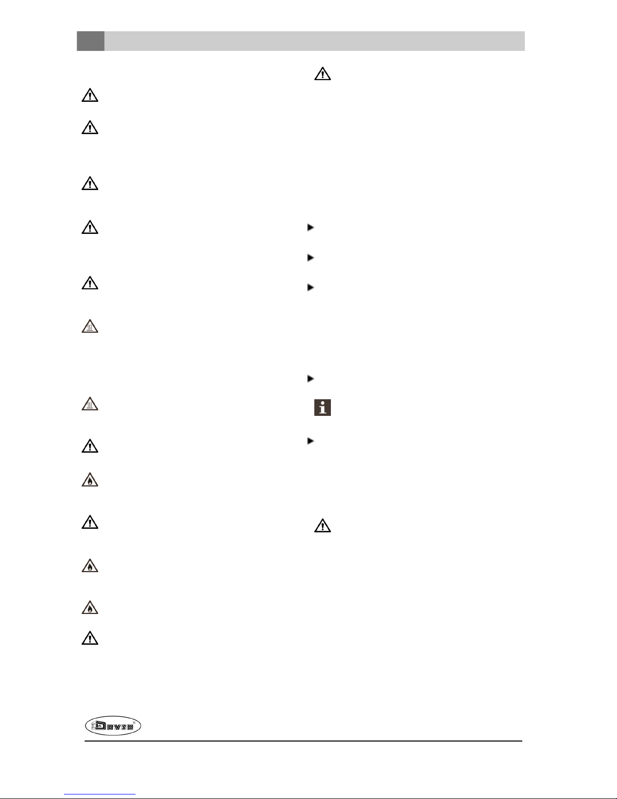
De schoorsteen moet minimaal 4meterhoog zijn.
Als vuistregel geldt: 60cm boven denok van het
dak.
Als de nok van het dak meer dan 3meter is
verwijderd van de schoorsteen: houd de maten aan
die in de volgendefiguur zijn aangegeven. A = het
hoogste punt van het dak binnen een afstand van
3meter.
Ventilatie van de ruimte
Voor een goede verbranding heeft het toestel lucht
(zuurstof) nodig. Die lucht wordt via regelbare
luchtinlaten aangevoerd vanuit de ruimte waar het
toestel is geplaatst.
Bij onvoldoende ventilatie vindt onvolledige
verbranding plaats, waardoor zich giftige
gassen in deruimte kunnen verspreiden.
Een vuistregel is dat de luchttoevoer5,5cm²/kW
moet zijn. Extra ventilatie is nodig:
Als het toestel in eenruimte staat die goedis
geïsoleerd.
Als er mechanische ventilatie is, bv een centraal
afzuigsysteem of een afzuigkapin een open
keuken.
U kunt voor extra ventilatie zorgen door een
ventilatierooster in debuitenmuur te laten plaatsen.
Zorg dat andereluchtverbruikende apparaten (zoals
eenwasdroger, ander verwarmingstoestel of
badkamerventilator) eeneigen buitenluchtaanvoer
hebben, of zijn uitgeschakeldwanneeru het toestel
stookt.
U kunt het toestel ook aansluiten op
buitenluchtaanvoer. Hiervoor is een aansluitset
meegeleverd. Extra ventilatie is dan niet nodig.
Vloer en wanden
De vloer waarop het toestel wordt geplaatst, moet
voldoende draagvermogen hebben. Voor het gewicht
van het toestel: zie de bijlage"Technische gegevens".
Bescherm een brandbare vloer door middel van
eenonbrandbare vloerplaat tegen warmte-
Page 12
12
Wijzigingen op grond van technische verbeteringen voorbehouden
uitstraling. Zie de bijlage"Afstandtot
brandbaar materiaal".
Verwijder brandbaar materiaal zoals linoleum,
tapijt, enzovoorts onderde onbrandbare
vloerplaat.
Zorg voor voldoende afstand tussen het toestel
en brandbare materialen zoals houtenwanden
en meubels.
Ook de aansluitbuis straalt warmte uit. Zorg
voor voldoende afstand of afscherming tussen
de aansluitbuis en brandbare materialen.
De vuistregel voor een enkelwandigebuis is
eenafstand van driemaal de diameter. Als een
bekledingsschelp rond debuis is aangebracht,
is een afstand van eenmaal de diameter
toelaatbaar.
Een vloerkleed moet minimaal 80cm van het
vuur verwijderd zijn.
Bescherm een brandbare vloer voor de kachel
met behulp van een onbrandbarevloerplaat
tegeneventueel uitvallendeassen. De
vloerplaat moet voldoen aan nationale normen.
Voor de afmetingen van de onbrandbare
vloerplaat: zie de bijlage "Afstand tot brandbaar
materiaal".
Voor verdereeisen in verband met
brandveiligheid: zie de bijlage "Afstand tot
brandbaar materiaal".
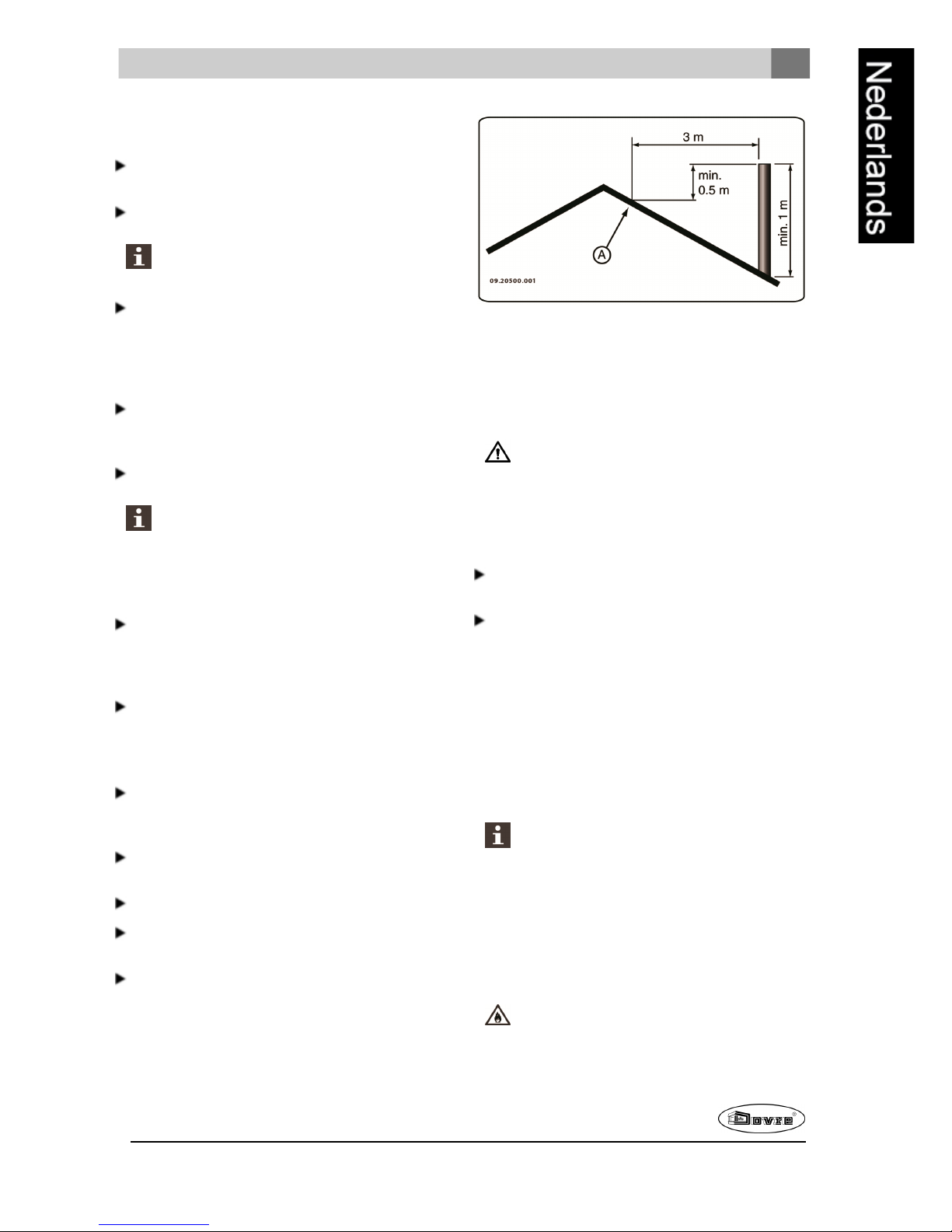
Productbeschrijving
1. Aansluitkraag
2. Deur
3. Zijglas
4. Grendel
5. Luchtschuif
Page 13
Wijzigingen op grond van technische verbeteringen voorbehouden
13
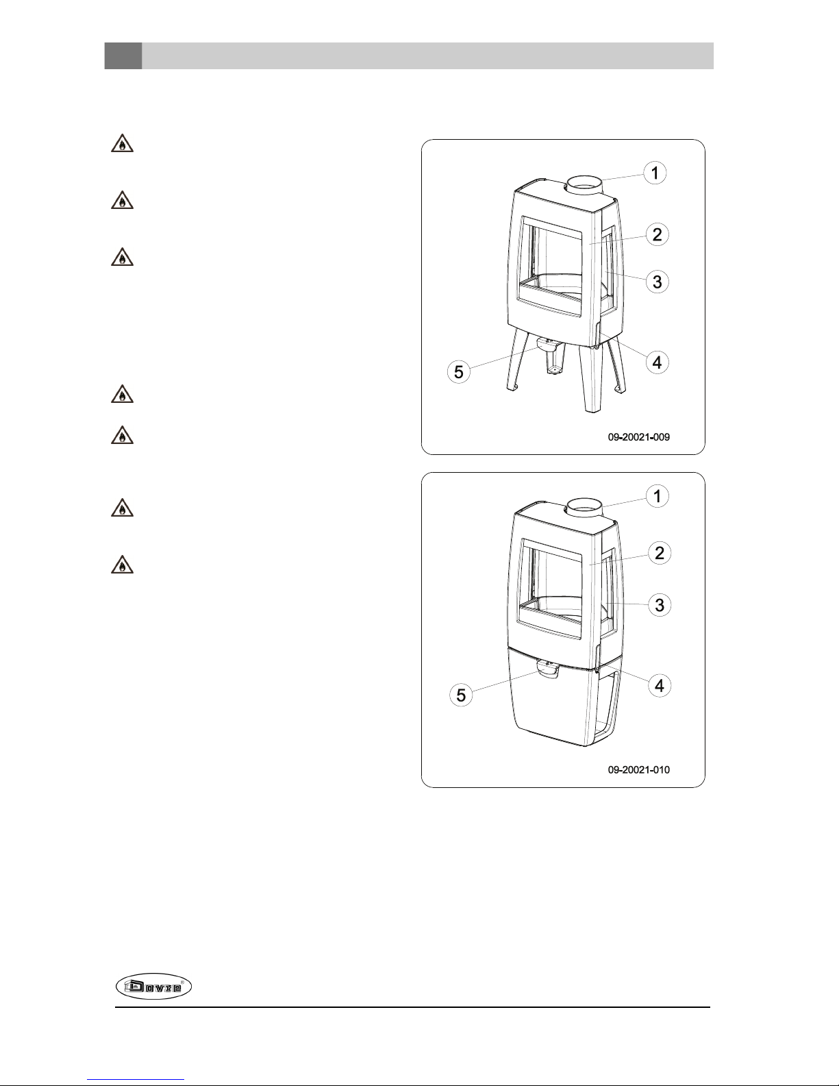
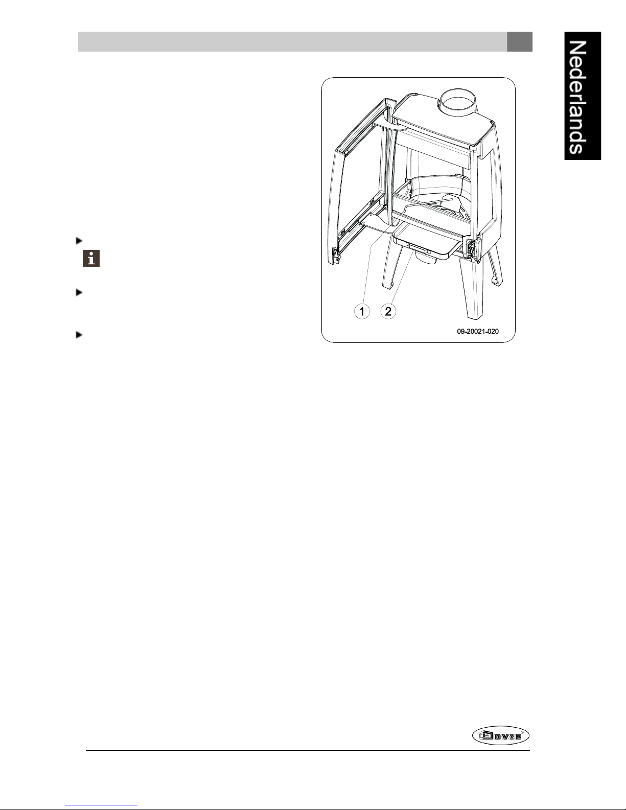
Deursluiting
Het toestel wordt geleverdmet de grendelknop (4)
gemonteerd. De deur wordt geopend door de
grendelknop in te drukken. Omdat de grendelknop
tijdens het gebruik warm wordt, is er een handschoen
bijgeleverddie u kunt gebruiken als beschermingvoor
uw hand.
Installatie
Algemene voorbereiding
Controleer het toestel onmiddellijk bij ontvangst op
(transport)schadeen eventuele anderegebreken.
Het toestel is aan de onderkant met schroeven op
de pallet gemonteerd.
Als u (transport)schade of gebreken hebt
geconstateerd, neem het toestel dan niet in
gebruik enstel de leverancier op de hoogte.
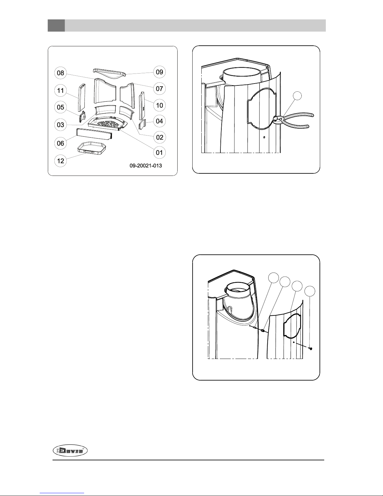
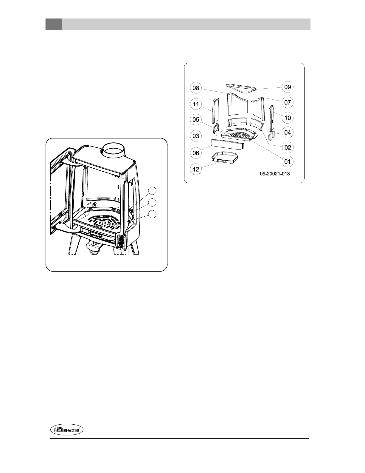
Verwijder de demontabeleonderdelen (vuurvaste
binnenplaten, stookrooster, topplaat, aslade) uit
het toestel voordat u het toestel gaat installeren.
Door demontabeleonderdelen te verwijderen,
kunt u het toestel gemakkelijker verplaatsen en
beschadiging voorkomen.
Let bij het verwijderen van demontabele
onderdelen op hun oorspronkelijke positie, om
ze later weer op de juiste plaats te kunnen
aanbrengen.
09-20021-011
1
2
3
1. Open de deur; zie volgende figuur.
09-20021-012
2. Verwijder de vuurvaste binnenplaten; zie volgende
figuur.
a. Verwijder eerst de vlamplaat(09).
De vlamplaat is aan de bovenzijde
bevestigd met een metalenclipje, dit is om
beschadiging tijdens het transport te
vermijden.
b. Verwijder de binnenplaten (10), (11), (07)en
(08) aan de zij- en achterkant
c. Verwijder devuurkorf aan de achterzijde (02)
en (03) en aan de voorkant(04), (05) en (06).
d. Verwijder het rooster en deaslade(01) en (12).
Vermiculiet binnenplaten zijn licht van
gewicht en bij levering meestal okerkleurig.
Zij isolerende verbrandingskamer zodat de
verbranding beter is.
Page 14
14
Wijzigingen op grond van technische verbeteringen voorbehouden
Uitneembare binnendelen
01 stookbodem
02 vuurkorf rechtsachter
03 vuurkorf linksachter
04 vuurkorf rechts
05 vuurkorf links
06 vuurkorf
07 binnenplaat zijkant rechtsachter
08 binnenplaat zijkant linksachter
09 vlamplaat binnenplaat
10 binnenplaat zijkant rechts
11 binnenplaat zijkant links
12 aslade
Schoorsteenaansluiting
voorbereiden
Bij het aansluitenvan het toestel op een schoorsteen
hebt u de keuze uit aansluitingaan de bovenzijde of
aande achterzijde van het toestel.
Optioneel is een hitteschild verkrijgbaar. Bij
toepassing van dit hitteschild kan de afstand tot
brandbaar materiaal verkleind worden. Zie bijlage
"Afstand tot brandbaarmateriaal". Voorde aansluiting
aande achterzijde moet de uitbreekplaat verwijderd
worden. Dit kan met behulp van een kniptang (1); zie
volgende figuur.
09-20021-014
1
Hitteschild monteren
Om het optioneel verkrijgbare hitteschild te monteren
gaat u als volgt te werk:
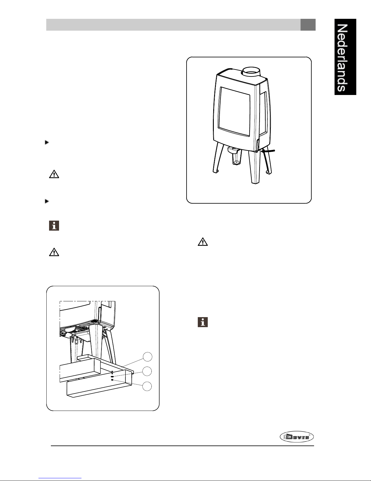
1. Schroef 2 draadeindenM6 (1) met afstandstuk (2)
op deachterwand.
2. Plaatst het hitteschild (3) en schroef dit vast met 2
flenskopschroeven M6 (4), zie volgendefiguur.
1
2
09-20021-023
3
4
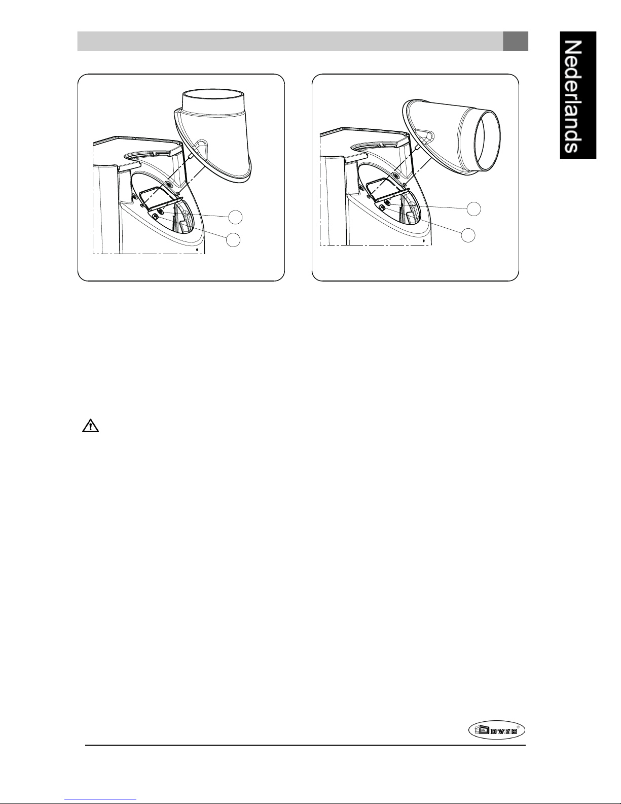
Aansluiten op de bovenzijde
Het toestel wordt standaard geleverd met de
aansluitkraag gemonteerdvooreen aansluiting aan de
bovenzijde, zie volgende afbeelding.
Page 15
Wijzigingen op grond van technische verbeteringen voorbehouden
15
09-20021-015
2
1
Aansluiten op de achterzijde
Voor de aansluitingop de achterzijde moet de positie
van de aansluitkraag gewijzigd worden. De
aansluitkraag is bevestigd met 2 moerenM8 (sleutel
13). Ga als volgt te werk:
1. Verwijder de vlamplaat.
2. Schroef de moeren los en verwijder de
aansluitkraag.
Controleer of het afdichtband op het
contactvlak niet is beschadigd. Vervang het
afdichtband als dat wel het geval is.
3. Plaats de aansluitkraag 180° gedraaid ten
opzichte van de oorspronkelijke positie, zie
volgende figuur.
09-20021-016
2
1
4. Monteer deaansluitkraag met de 2 moerenM8.
5. Plaats de vlamplaat terug.
Buitenluchtaansluiting
voorbereiden
Als het toestel wordt geplaatst in eenruimte die
onvoldoende is geventileerd, kunt u de aansluitset
voor het aanvoerenvan buitenlucht op het toestel
aansluiten.
De luchtaanvoerbuis heeft een diameter van 100mm.
Bij toepassing van een gladde buis mag deze buis
maximaal 12meter lang zijn. Bij gebruik van
hulpstukken zoals bochten moet u per hulpstuk de
maximale lengte (12meter) met 1meterverminderen.
Buitenluchtaansluiting via de wand
1. Maak een aansluitgat in de wand (raadpleeg de
bijlage "Afmetingen", voorde juiste positie van het
aansluitgat).
2. Sluit de luchtaanvoerbuis hermetisch af op de
muur.
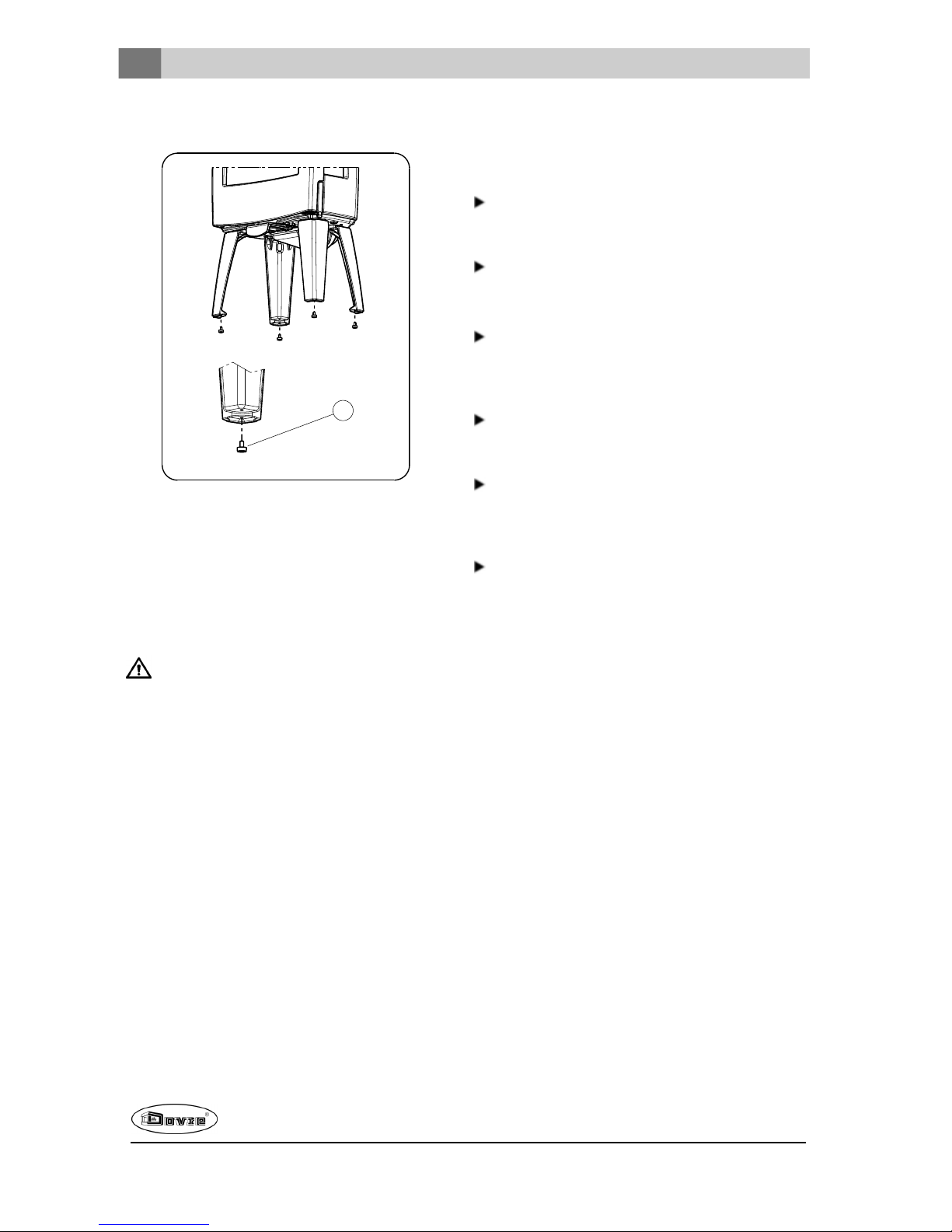
Plaatsen en aansluiten
1. Zet het toestel op de juiste plaats, vlak en
waterpas. Het toestel is uitgevoerd met
stelvoetjes die al op het toestel zijn gemonteerd of
worden bijgeleverd. Gebruik deze stelvoetjes
zodat het toestel perfect waterpas kan worden
Page 16
16
Wijzigingen op grond van technische verbeteringen voorbehouden
gesteld.
09-20021-017
1
2. Sluit het toestel hermetisch aan op de
schoorsteen.
3. Bij buitenluchtaansluiting: sluit de aanvoervan
buitenlucht aan op de aansluitset die op het toestel
is gemonteerd.
4. Plaats alle gedemonteerde onderdelen opde juiste
plaats terug in het toestel.
Laat het toestel nooit branden zonder de
vuurvaste binnenplaten.
Het toestel is nu klaar voorgebruik.
Gebruik
Eerste gebruik
Wanneer u het toestel voorhet eerst gebruikt, stook
het danenkele uren flink door. Hierdoor zal de
hittebestendigelak uitharden. Hierbij kan wel wat rook
en geurhinder ontstaan. Zet eventueel in de ruimte
waar het toestel staat de ramen endeuren even open.
Brandstof
Dit toestel is alleen geschikt voor het stoken van
natuurlijk hout; gezaagden gekloofd en voldoende
droog.
Gebruik geen andere brandstoffen, want die kunnen
leiden tot ernstige schadeaan het toestel.
De volgende brandstoffen mag u niet gebruiken omdat
zij het milieu vervuilen, en omdat zij het toestel en de
schoorsteen sterk vervuilen waardoor
schoorsteenbrand kan ontstaan:
Behandeld hout, zoals sloophout, geverfd hout,
geïmpregneerd hout, verduurzaamdhout, multiplex
en spaanplaat.
Kunststof, oud papier enhuishoudelijk afval.
Hout
Gebruik bij voorkeur hard loofhout zoals eik, beuk,
berk en fruitbomenhout. Dit hout brandt langzaam
met rustige vlammen. Naaldhout bevat meerhars,
brandt sneller en geeft meer vonken.
Gebruik gedroogdhout met een vochtpercentage
van maximaal 20%. Hiervoor moet het hout
minstens 2 jaar zijn gedroogd.
Zaaghet hout op maat en klief het als het nog vers
is. Vers hout klieft gemakkelijker en gekloven hout
droogt beter. Bewaar het hout onder een afdek
waar dewind vrij spel heeft.
Gebruik geen nat hout. Nat hout geeft geen warmte
omdat alle energie gaat zitten in het verdampen
van vocht. Dit geeft veel rook en roetaanslag op de
deur van het toestel en in deschoorsteen. De
waterdamp condenseert in het toestel en kan langs
naden uit het toestel lekken en zwarte vlekken op
de vloergeven. De waterdamp kan ook in de
schoorsteen condenseren encreosoot vormen.
Creosoot is zeer brandbaar en kan
schoorsteenbrand veroorzaken.
Aanmaken
U kunt controleren of de schoorsteen voldoende trek
heeft door boven de vlamplaat eenprop krantenpapier
aante steken. Bij een koudeschoorsteen is er vaak
onvoldoende trek in de schoorsteen enkan errook in
de kamer komen. Door het toestel op dehier
beschreven manier aan te maken, voorkomt u dit
probleem.
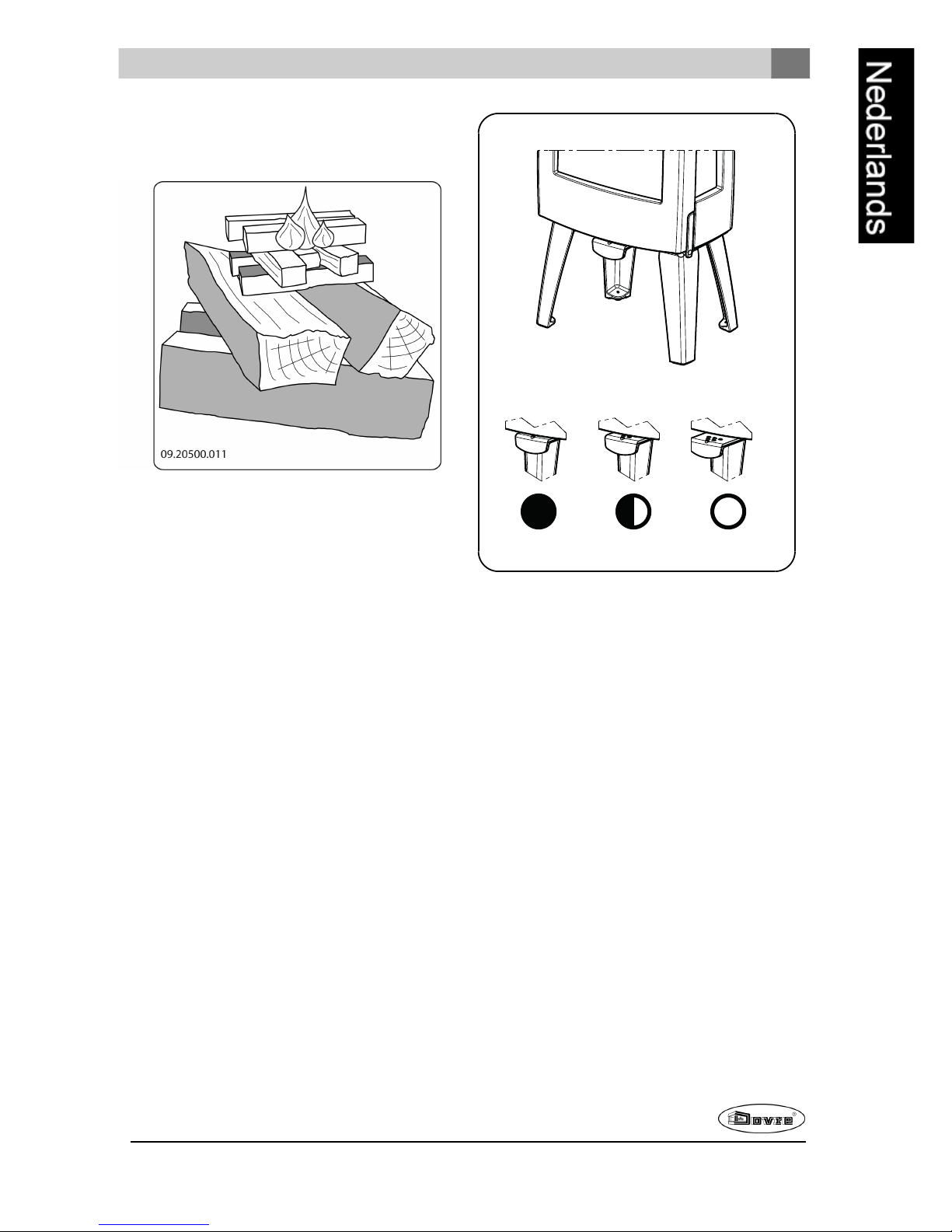
1. Stapel twee lagen middelgrote houtblokken
kruislings op elkaar.
2. Stapel bovenopde houtblokken twee lagen
aanmaakhoutjes kruislings op elkaar.
Page 17
Wijzigingen op grond van technische verbeteringen voorbehouden
17
3. Legeen aanmaakblokje tussen de onderste laag
aanmaakhoutjes en steek het aanmaakblokje aan
volgens de instructies op de verpakking.
4. Sluit de deur van het toestel en zet de primaire
luchtinlaat en de secundaireluchtinlaat van het
toestel open; zie volgendefiguur.
5. Laat het aanmaakvuur flink doorbranden totdat het
eengloeiend houtskoolbedis geworden. Hierna
kunt u een volgende vulling doen enhet toestel
gaan regelen; zie de paragraaf "Stoken met hout".
09-20021-018
CBA
C:
o o o Primaire lucht open (tijdens aanmaken)
o o Secundairelucht open (glasspoeling)
o Lucht voor naverbranding open
B:
o o Secundairelucht open (glasspoeling)
o Lucht voor naverbranding open
A:
o Lucht voor naverbranding open
(voorgoede verbranding nooit helemaal
sluiten)
Stoken met hout
Nadat u de instructies voorhet aanmaken hebt
gevolgd:
1. Open langzaam de deur van het toestel.
2. Verdeel het houtskoolbed gelijkmatig over de
stookvloer.
3. Stapel enkele houtblokken ophet houtskoolbed.
Page 18
18
Wijzigingen op grond van technische verbeteringen voorbehouden
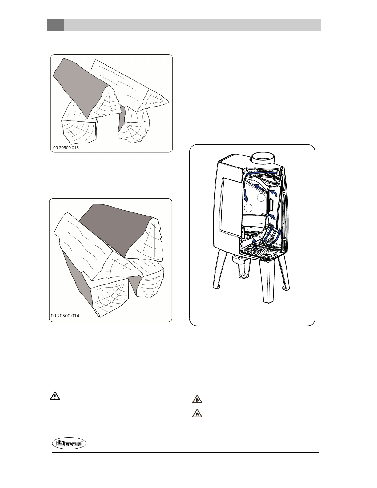
Losse stapeling
Bij een losse stapelingverbrandt het hout vlug omdat
de zuurstof elk stuk hout gemakkelijk kan bereiken.
Gebruik eenlosse stapeling als u kort wilt stoken.
Compacte stapeling
Bij een compacte stapeling verbrandt het hout
langzamer omdat de zuurstof maar enkele stukken
hout kan bereiken. Gebruik een compacte stapeling
als u langer wilt stoken.
4. Sluit de deur van het toestel.
5. Sluit de primaire luchtinlaat en laat de secundaire
luchtinlaat open staan.
Vul het toestel voor maximaal een derde.
Regeling verbrandingslucht
Het toestel heeft diverse voorzieningen voor de
luchtregeling; zie volgendefiguur.
Het toestel heeft één luchtschuif die zowel de primaire
lucht als de secundaire lucht regelt. Als de luchtschuif
geheel is uitgetrokken is de primaireen secundaire
luchtinlaat open. Naarmate de luchtschuif verder
wordt ingedrukt sluit zich de primaireluchtinlaat en
daarna de secundaireluchtinlaat. Als de luchtschuif
geheel gesloten is blijft eenkleine luchtopeningopen
om de naverbrandingonder de vlamplaat te verzorgen.
09-20021-019
1
2
3
De primaire lucht regelt de lucht onder het rooster (1).
De secundaire lucht regelt de lucht voor het glas (airwash) (2).
De achterwand heeft onderde vlamplaat permanente
luchtopeningen (3) die zorgen voor de naverbranding.
Adviezen
Stook nooit met open deur.
Stook het toestel regelmatig flink door.
Page 19
Wijzigingen op grond van technische verbeteringen voorbehouden
19
Als u langdurig op lage stand stookt, kan zich
in de schoorsteen een afzetting vormen van
teer encreosoot. Teeren creosoot zijn zeer
brandbaar. Als de afzetting van deze stoffen te
groot wordt, kan bij een plotselinge hoge
temperatuur een schoorsteenbrandontstaan.
Door regelmatig flink doorstoken, verdwijnen
eventuele afzettingen van teer encreosoot.
Daarnaast kan zich bij te laag stoken teer
afzetten op deruit en deur van het toestel.
Bij een milde buitentemperatuur is het dus
beterom het toestel een paar uur intens te
laten branden, dan lange tijd laag te stoken.
Regel deluchttoevoer met de luchtschuif.
De luchtinlaat belucht niet alleenhet vuurmaar
ook het glas, zodat het glas niet snel vervuilt.
Zet de primaireluchtinlaat tijdelijk open als de
luchttoevoer via de secundaire luchtinlaat
onvoldoende is of als u het vuurwilt aanwakkeren.
Regelmatig een kleine hoeveelheid houtblokken
bijvullen is beter dan veel houtblokken tegelijk.
Doven van het vuur
Vul geen brandstof bij en laat de kachel gewoon
uitgaan. Als een vuur wordt getemperd door de
luchttoevoer te verminderen, komen schadelijke
stoffen vrij. Laat daarom het vuurvanzelf uitbranden.
Houd toezicht op het vuurtotdat het goed is gedoofd.
Als het vuur volledig is gedoofd kunnen alle
luchtschuiven worden gesloten.
Ontassen
Na het stoken van hout blijft een relatief kleine
hoeveelheid as over. Dit asbed is een goede isolator
voor destookbodem engeeft een betere verbranding.
Laat daarom gerust een dun laagje as op de
stookbodem liggen.
De luchttoevoerdoor destookbodem mag echter niet
worden belemmerd en ermag zich geen as ophopen
achter een gietijzeren binnenplaat. Verwijder daarom
regelmatig de overtollige as.
1. Open de deur van het toestel.
2. Gebruik het trekschepje om de overtollige assen
door het rooster in de aslade te schrapen
3. Verwijder de aslade met behulp van de
bijgeleverde handschoen en leeg de aslade.
4. Plaats de asladeterug en sluit de deur van het
toestel.
Nevel en mist
Nevel en mist belemmeren de afvoer van rookgassen
door de schoorsteen. Rook kan neerslaanen
stankoverlast geven. Als het niet echt nodig is, kunt u
bij nevel enmist beter niet stoken.
Eventuele problemen
Raadpleegde bijlage"Diagnoseschema" om
eventuele problemen bij het gebruik van het toestel op
te lossen.
Onderhoud
Volg de onderhoudsinstructies in dit hoofdstuk om het
toestel in goede staat te houden.
Page 20
20
Wijzigingen op grond van technische verbeteringen voorbehouden
Schoorsteen
In veel landen bent u wettelijk verplicht de
schoorsteen te laten controleren en onderhouden.
Aan het begin van het stookseizoen: laat de
schoorsteen vegendoor een erkend
schoorsteenveger.
Tijdens het stookseizoenen nadat de schoorsteen
lange tijd niet is gebruikt: laat de schoorsteen
controleren op roet.
Na afloop van het stookseizoen: sluit de
schoorsteen af met een prop krantenpapier.
Schoonmaken en ander
regelmatig onderhoud
Maak het toestel niet schoon wanneer het nog
warm is.
Maak de buitenkant van het toestel schoon met
eendrogeniet pluizende doek.
Na afloop van het stookseizoenkunt u de binnenkant
van het toestel goed schoonmaken:
Verwijder eventueel eerst de vuurvaste
binnenplaten. Zie het hoofdstuk "Installatie" voor
instructies voor het verwijderenen aanbrengen van
binnenplaten.
Maak eventueel deluchtaanvoerkanalen schoon.
Verwijder de vlamplaat bovenin het toestel en
maak deze schoon.
Vuurvaste binnenplaten controleren
De vuurvaste binnenplaten zijn verbruiksonderdelen
die aan slijtage onderhevig zijn. Vermiculiet
binnenplaten zijn kwetsbaar. Stoot niet met
houtblokken tegen de binnenplaten. Controleer de
binnenplaten regelmatig en vervang ze indiennodig.
Zie het hoofdstuk "Installatie" voor instructies voor
het verwijderen en aanbrengen van binnenplaten.
De isolerende vermiculiet of chamotte
binnenplaten kunnen haarscheuren gaan
vertonen, maardat heeft geennadelig effect op
hunwerking.
Gietijzeren binnenplatengaan lang mee als u
regelmatig as verwijdert die zich mogelijk
erachter ophoopt. Als opgehoopte as achter
eengietijzeren plaat niet wordt verwijderd, kan
de plaat de warmte niet meer afgeven aan de
omgeving en kan de plaat vervormen of
scheuren.
Laat het toestel nooit branden zonder de
vuurvaste binnenplaten.
Glas schoonmaken
Goed schoongemaakt glas neemt minder snel vuil op.
Ga als volgt te werk:
1. Verwijder stof enloszittend roet met een droge
doek.
2. Maak het glas schoonmet kachelruitenreiniger:
a. Breng kachelruitenreiniger aan op een
keukenspons, wrijf het geheleglasoppervlak in
en laat even inwerken.
b. Verwijder het vuil met een vochtige doek of
keukenpapier.
3. Maak het glas nogmaals schoon met een gewoon
glasreinigingsproduct.
4. Wrijf het glas schoonmet een droge doek of
keukenpapier.
Gebruik geen schurendeof bijtende producten om
het glas schoon te maken.
Gebruik schoonmaakhandschoenen om uw
handente beschermen.
Als het glas van het toestel is gebroken of
gebarsten, moet dit glas worden vervangen
voordat u het toestel opnieuw in gebruik neemt.
Voorkom dat kachelruitreiniger tussen het glas
en degietijzeren deur loopt.
Onderhoud geëmailleerde kachel
Reinig het toestel nooit als het nog warm is. Het
reinigenvan het geëmailleerde oppervlak van de
kachel kunt u het beste doen met zachte groenezeep
en lauw water. Gebruik zo min mogelijk water, wrijf
het oppervlak goed droog en voorkom roestvorming.
Gebruik nooit staalwol of een anderschuurmiddel. Zet
nooit een waterketel direct op een geëmailleerde
kachel; gebruik eenonderzetter en voorkom
beschadigingen.
Page 21
Wijzigingen op grond van technische verbeteringen voorbehouden
21
Smeren
Hoewel gietijzer enigszins zelfsmerend is, moet u
bewegende delen toch regelmatig smeren.
Smeerde bewegende delen (zoals
geleidersystemen, scharnierpennen, grendels en
luchtschuiven)met hittevast vet dat verkrijgbaar is
bij de vakhandel.
Lakbeschadigingen bijwerken
Kleine lakbeschadigingenkunt u bijwerken met een
spuitbus speciale hittebestendigelak dieverkrijgbaar
is bij uw leverancier.
Het geëmailleerde oppervlak
bijwerken
Emailleren is een artisanaal proces dat maakt dat er
kleine kleurverschillen en beschadigingen op het
toestel kunnen voorkomen. De toestellen ondergaan
in de fabriek een visuele controle, dat wil zeggen, de
controleur kijkt op een afstand van 1 meter gedurende
10 seconden naar het oppervlak.
Eventuelebeschadigingen die dan niet opvallen
worden als OK beschouwd. Bij het toestel is een
speciale hittebestendige lak meegeleverd waarmee
kleine (transport) beschadigingenkunnen worden
bijgewerkt.
Breng de hittebestendige lak in dunne laagjes aan en
laat het goed drogen voordat het toestel in gebruik
genomen wordt.
Sommigekleuren email zijn gevoelig voor
verandering van temperatuur. Hierdoor kan het
voorkomen dat de kleur verandert tijdens het
gebruik van het toestel. Als het toestel is afgekoeld
keert de oorspronkelijke kleur van het email terug.
Als geëmailleerde oppervlakken zeer heet worden
kunnen er haarscheurtjes ontstaan. Dit is een
normaal verschijnsel en heeft geen invloed op het
functionerenvan dekachel.
Zorg dat de kachel niet wordt overbelast. Bij
overbelasting wordt de oppervlaktetemperatuur
extreem hoogen kan er blijvende schadeaan
het email ontstaan.
Afdichting controleren
Controleer of het afdichtingskoordvan dedeur nog
goed afsluit. Afdichtkoordverslijt en moet tijdig
worden vervangen.
Controleer het toestel op luchtlekken. Kit eventuele
kierendicht met kachelkit.
Laat de kit goed uitharden voordat u het toestel
aanmaakt, anders blaast het vocht in de kit op
en ontstaat opnieuw een lek.
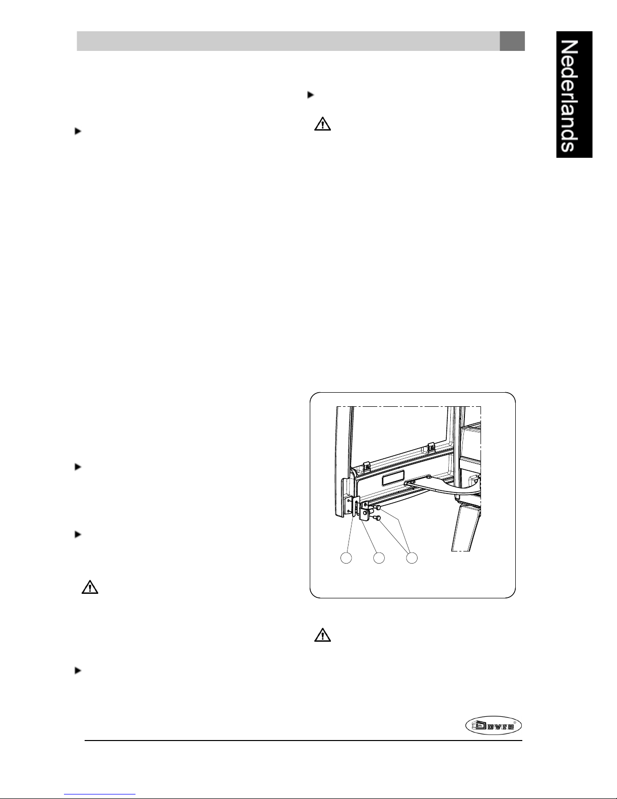
Sluiting deur bijstellen
Controleer of de deur goed sluit. Indien nodig kan de
sluiting van de deur stakker of losser ingesteld worden
door de afstandvan desluitnok tot de deur te wijzigen.
Ga als volgt te werk:
1. Open de deur. De sluitnok (2) is nu zichtbaar en
toegankelijk, zie volgende figuur.
2. Draai detwee schroeven (1)los, waarmee de
sluitnok is bevestigd.
3. Door een opvulplaatje (3) achter de sluitnok (2)te
verwijderen sluit de deur strakker. Als de deur te
strak sluit brengt u een extra opvulplaatje achter
de sluitnok aan.
4. Draai detwee schroeven van de sluitnok weer
vast ensluit de deur.
09-20021-024
123
Glas vervangen
Als het glas van het toestel is gebroken of
gebarsten, moet dit glas worden vervangen
voordat u het toestel opnieuw in gebruik neemt.
Page 22
22
Wijzigingen op grond van technische verbeteringen voorbehouden
Om het zijglas te vervangen moeten eerst alle
binnenpanelen en de luchtgeleiderworden verwijderd.
De luchtgeleider is bevestigd met eenmoer M8
midden boven in het toestel. Ga als volgt te werk:
1. Schroef de twee glasbevestigingen met
onderdelen (1)en (2) los en verwijder het glas (3),
zie volgende figuur.
2. Controleer de glasafdichting en breng indien nodig
eennieuw afdichtkoordaan.
3. Plaats het nieuwe glas in de sponning en schroef
de glasbevestigingen vast.
09-20021-025
1
2
3
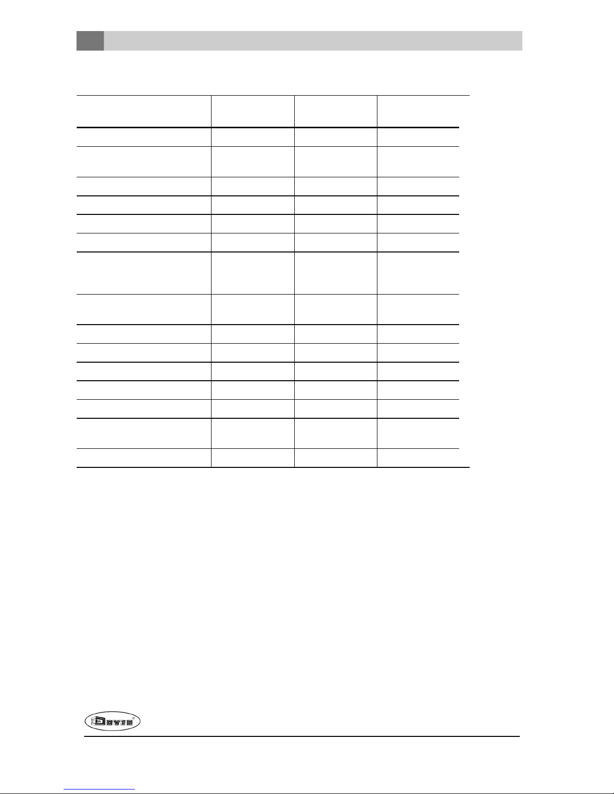
Wisselstukken Sense
Sense 100/103/200/203
Pos. Artikelnr. Omschrijving Aantal
01 03.66544.002 stookbodem 1
02 03.77429.002 vuurkorf rechtsachter 1
03 03.77428.000 vuurkorf linksachter 1
04 03.77425.002 vuurkorf rechts 1
05 03.77424.002 vuurkorf links 1
06 03.77423.002 vuurkorf 1
07 03.77523.000 binnenplaat zijkant
rechtsachter
1
08 03.77522.000 binnenplaat zijkant
linksachter
1
09 03.76181.000 vlamplaat
binnenplaat
1
10 03.77525.000 binnenplaat zijkant
rechts
1
11 03.77524.002 binnenplaat zijkant
links
1
12 03.05216.000 aslade 1
Sense 300/303/400/403
Pos. Artikelnr. Omschrijving Aantal
01 03.66549.002 stookbodem 1
02 03.77444.002 vuurkorf rechtsachter 1
03 03.77443.000 vuurkorf linksachter 1
04 03.77442.002 vuurkorf rechts 1
05 03.77441.002 vuurkorf links 1
06 03.77440.002 vuurkorf 1
Page 23

Wijzigingen op grond van technische verbeteringen voorbehouden
23
07 03.77548.000 binnenplaat zijkant
rechtsachter
1
08 03.77547.000 binnenplaat zijkant
linksachter
1
09 03.76188.000 vlamplaat
binnenplaat
1
10 03.77550.000 binnenplaat zijkant
rechts
1
11 03.77549.002 binnenplaat zijkant
links
1
12 03.05216.000 aslade 1
Page 24
Bijlage 1: Technische gegevens
Model
Sense
100/103/200/203
Sense
100/103/200/203
Sense
300/303/400/403
Nominaal vermogen 4,9 kW 7,0 kW 9,0 kW
Schoorsteenaansluiting
(diameter)
150mm 150 mm 150 mm
Gewicht 105kg - 125kg 105kg - 125kg 150kg - 180kg
Aanbevolenbrandstof Hout Hout Hout
Kenmerk brandstof, max. lengte 33 cm 33 cm 40 cm
Massadebiet van rookgassen 4,5 g/s 5,1 g/s 7,3 g/s
Rookgastemperatuurgemeten
in de
meetsectie
247°C 274 °C 274 °C
Temperatuur gemeten aan de
uitgang van het toestel
317°C 351 °C 352 °C
Minimum trek 12 Pa 12 Pa 12 Pa
CO-emissie (13%O2) 0,18 % 0,07 % 0,08%
NOx-emissie (13% O2) 81 mg/Nm³ 89 mg/Nm³ 75 mg/Nm³
CnHm-emissie (13%O2) 173 mg/Nm³ 76 mg/Nm³ 69 mg/Nm³
Stofemissie 27 mg/Nm³ 25 mg/Nm³
Stofemissie volgens NS3058NS3059
2,87 gr/kg 2,87 gr/kg
Rendement 79,5 % 80 % 80%
24
Wijzigingen op grond van technische verbeteringen voorbehouden
Page 25
Wijzigingen op grond van technische verbeteringen voorbehouden
25
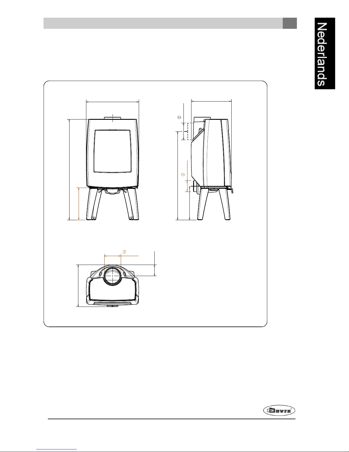
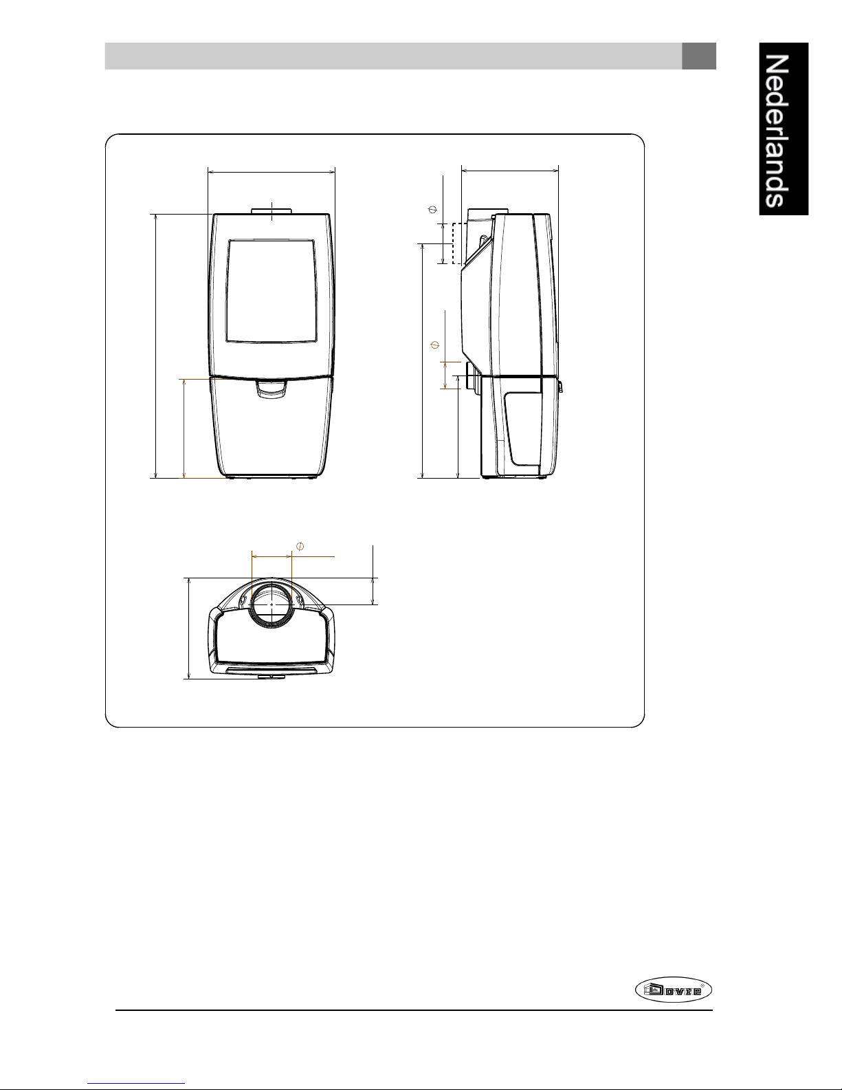
Bijlage 2: Afmetingen
Sense 100
09-20021-001
4 7 0
9 0 0
2 8 5
3 6 0
3 0 0
7 9 0
1 5 0
1 0 0
1 5 0
1 0 0
3 7 5
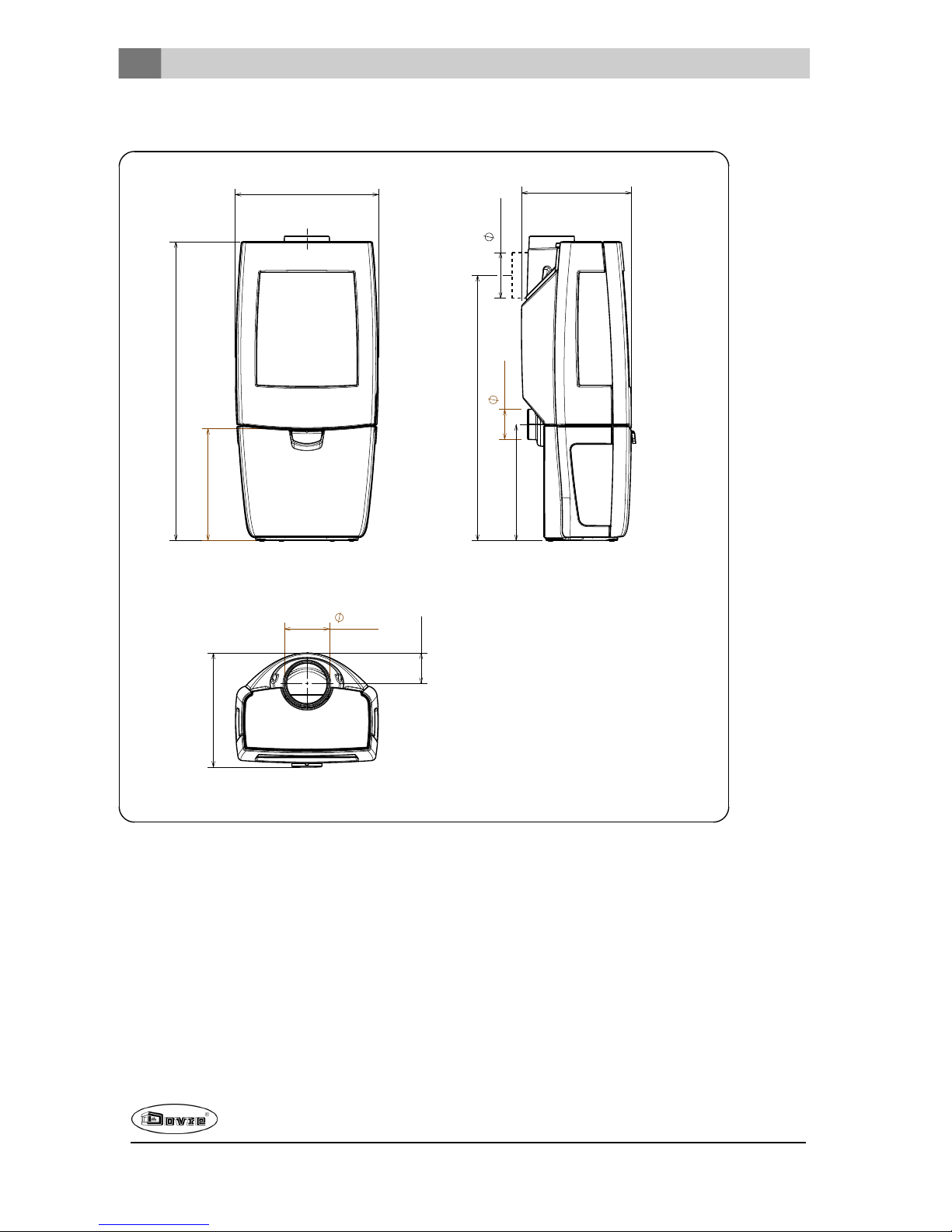
Page 26
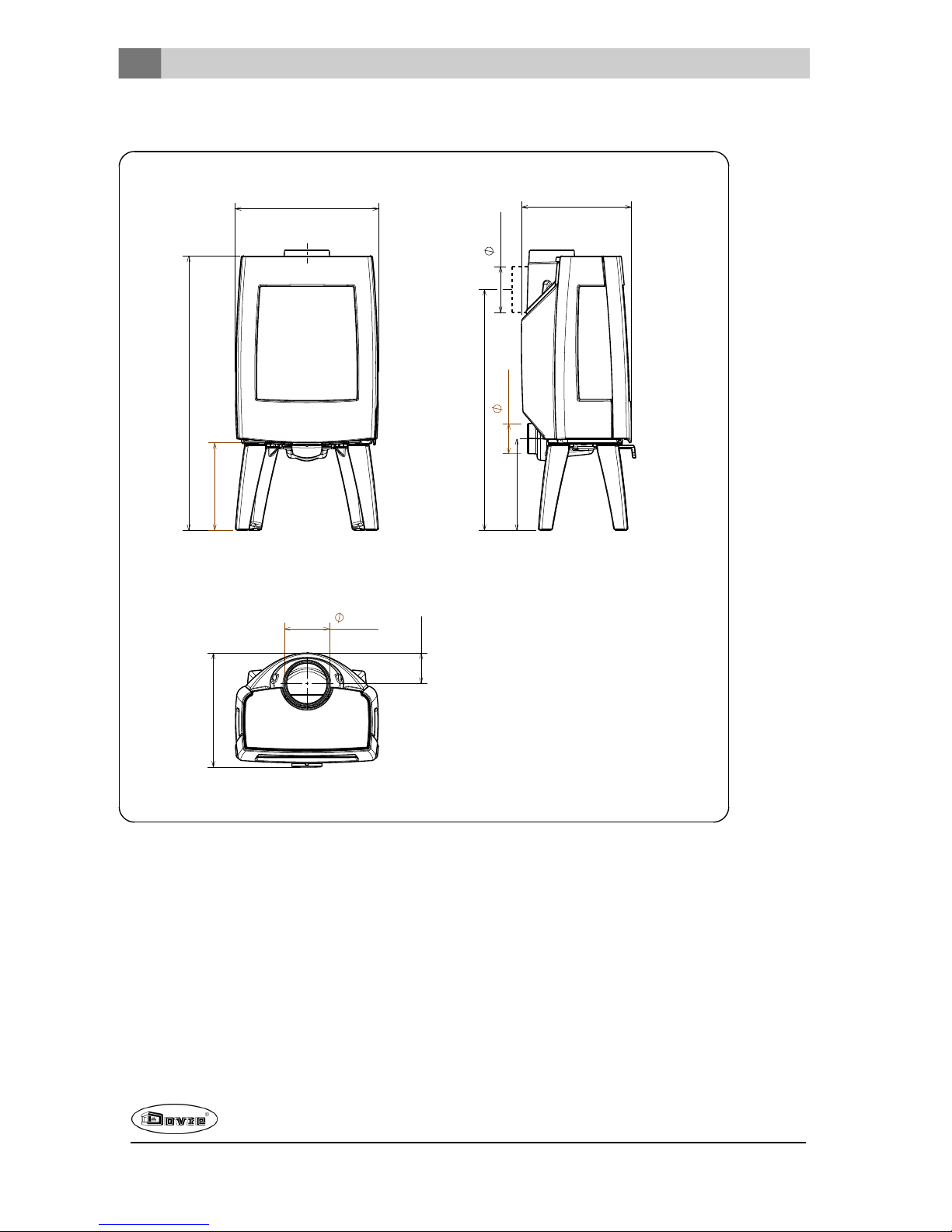
Sense 103
09-20021-002
4 7 0
9 0 0
2 8 5
3 6 0
3 0 0
7 9 0
1 5 0
1 0 0
1 5 0
1 0 0
3 7 5
26
Wijzigingen op grond van technische verbeteringen voorbehouden
Page 27
Wijzigingen op grond van technische verbeteringen voorbehouden
27
Sense 200
09-20021-003
4 7 0
9 8 0
3 6 5
3 6 0
1 5 0
3 8 0
8 7 0
1 0 0
1 5 0
1 0 0
3 7 5
Page 28
Sense 203
09-20021-004
4 7 0
9 8 0
3 6 5
3 6 0
1 5 0
3 8 0
8 7 0
1 0 0
1 5 0
1 0 0
3 7 5
28
Wijzigingen op grond van technische verbeteringen voorbehouden
Page 29
Wijzigingen op grond van technische verbeteringen voorbehouden
29
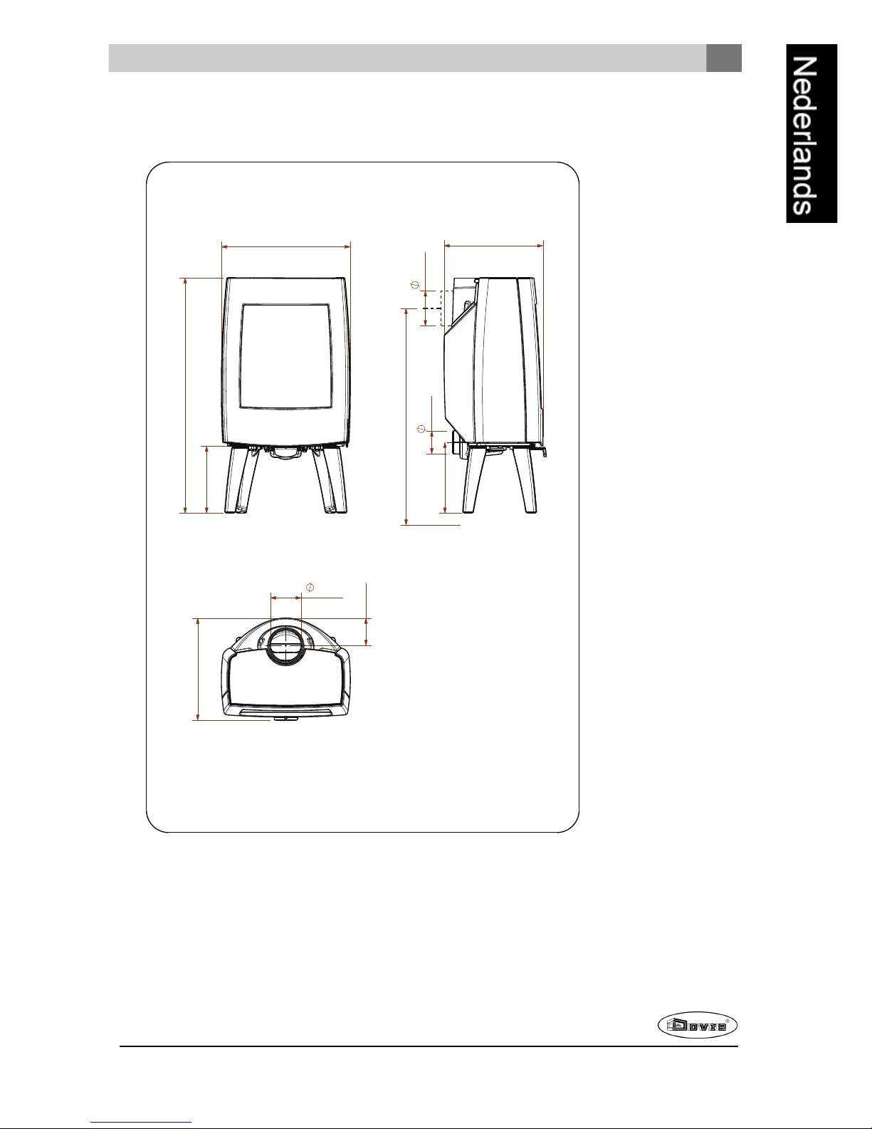
Sense 300
1 0 1 0
2 9 0
5 5 5
1 5 0
1 0 0
4 2 5
3 0 5
8 8 0
1 5 0
4 4 0
1 1 5
09-20021-005
Page 30
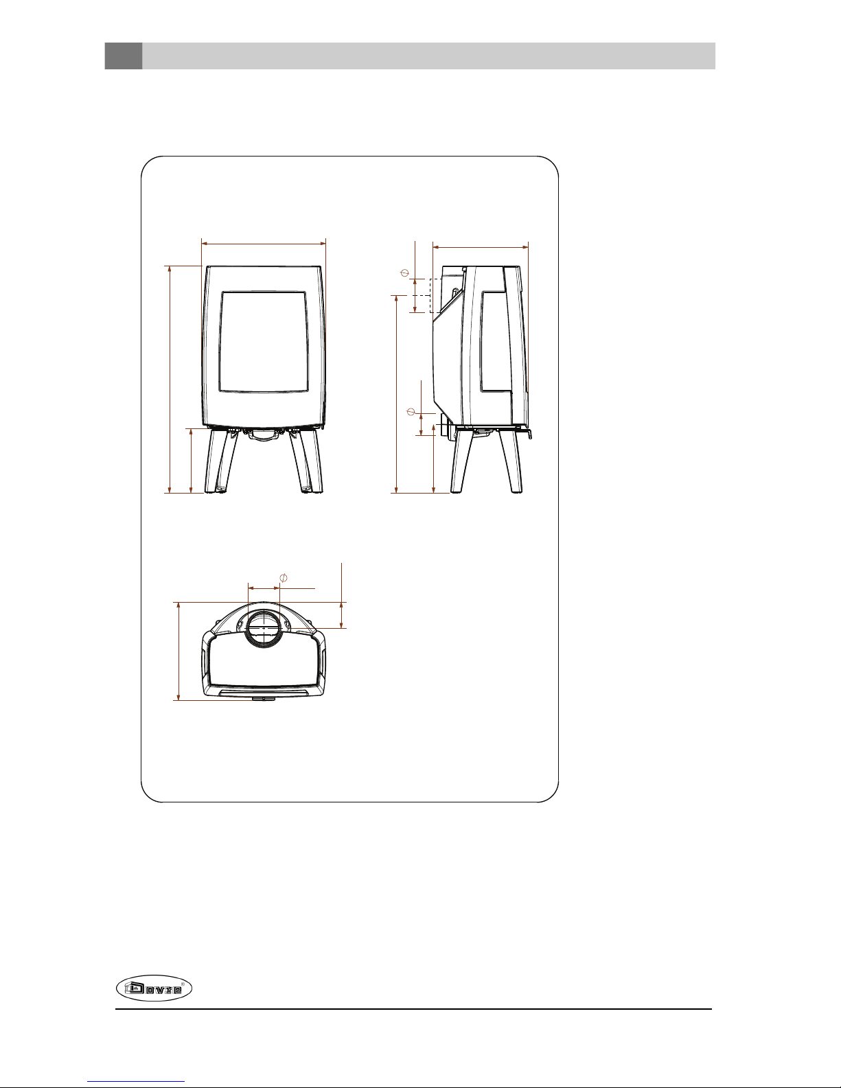
Sense 303
1 0 1 0
5 5 5
2 9 0
8 8 0
1 5 0
1 0 0
3 0 5
4 2 5
4 4 0
1 1 5
1 5 0
09-20021-006
30
Wijzigingen op grond van technische verbeteringen voorbehouden
Page 31

Wijzigingen op grond van technische verbeteringen voorbehouden
31
Sense 400
4 3 0
1 1 6 0
5 5 5
1 5 0
1 0 0
4 5 0
1 0 2 5
4 2 5
1 5 0
4 4 0
1 1 5
09-20021-007
Page 32

Sense 403
1 1 6 0
4 3 0
5 5 5
1 5 0
1 0 0
4 5 0
1 0 2 5
4 2 5
1 5 0
4 4 0
1 1 5
09-20021-008
32
Wijzigingen op grond van technische verbeteringen voorbehouden
Page 33

Wijzigingen op grond van technische verbeteringen voorbehouden
33
Bijlage 3: Afstand tot brandbaar materiaal
Sense 100/103/200/203 4,9 kW - 7 kW - Minimale afstanden in millimeters
voor uitvoering zonder hitteschild
1 Brandbaarmateriaal
2 Onbrandbaar materiaal 100mm
Let op! Om de toevoer van verbrandingslucht te garanderen moet, wanneer er geen buitenluchtaansluiting
is voorzien, de afstand van deaansluitkraag voor de buitenlucht tot de muur minimaal 20 mm zijn. In
voorkomende gevallen kan de aansluitkraag gedemonteerd worden.
Page 34

Sense 100/103/200/203 4,9 kW - 7 kW - Minimale afstanden in millimeters
voor uitvoering met hitteschild
1 Brandbaarmateriaal
2 Onbrandbaar materiaal 100mm
Let op! Om de toevoer van verbrandingslucht te garanderen moet, wanneer er geen buitenluchtaansluiting
is voorzien, de afstand van deaansluitkraag voor de buitenlucht tot de muur minimaal 20 mm zijn. In
voorkomende gevallen kan de aansluitkraag gedemonteerd worden.
34
Wijzigingen op grond van technische verbeteringen voorbehouden
Page 35

Wijzigingen op grond van technische verbeteringen voorbehouden
35
Sense 300/303/400/403 - 9 kW - Minimale afstanden in millimeters voor
uitvoering zonder hitteschild
* with/without
sideglass
2
1
09-20021-031
Page 36

Sense 300/303/400/403 - 9 kW - Minimale afstanden in millimeters voor
uitvoering met hitteschild
* with/without
sideglass
1
2
09-20021-032
Sense - Afmetingen onbrandbare vloerplaat
09-20021-030
B
B
A
36
Wijzigingen op grond van technische verbeteringen voorbehouden
Page 37

Wijzigingen op grond van technische verbeteringen voorbehouden
37
Minimale afmetingen onbrandbare vloerplaat
A (mm) B (mm)
Din 18891 500 300
Duitsland 500 300
Finland 400 100
Noorwegen 300 5
Page 38

Bijlage 4: Diagnoseschema
Probleem
Hout wil niet doorbranden
Geeft onvoldoende warmte
Rookterugslag tijdens het bijvullen
Toestel brandt te hevig, niet goed regelbaar
Aanslag op het glas
mogelijke oorzaak mogelijke oplossing
Onvoldoende trek
Een koudeschoorsteen creëert vaakonvoldoende trek. Volg de
instructiesvoor het aanmaken in het hoofdstuk"Gebruik"; open een
raam.
Hout te vochtig Gebruik hout met maximaal20% vocht.
Afmetingen hout te groot
Gebruik kleine stukjes aanmaakhout. Gebruik gekloven houtblokken
met een omtrek vanmaximaal 30 cm.
Stapeling hout niet correct
Stapel het hout zodanig dat er voldoende lucht tussende
houtblokken kan stromen (losse stapeling, zie "Stokenmet hout").
Werking van de schoorsteen
onvoldoende
Controleer of de schoorsteen aan de voorwaarden voldoet:
minimaal4 meter hoog, juiste diameter, goed geïsoleerd, gladde
binnenzijde, niette veelbochten, geen obstructiesin de schoorsteen
(vogelnest, te veel roetafzetting), hermetisch dicht (geen kieren).
Uitmonding vande schoorsteen niet
correct
Voldoende hoog boven het dakvlak, geen obstructiesin de
nabijheid.
Instelling vande luchtinlaten niet correct Opende luchtinlaten volledig.
Aansluiting van het toestelmet de
schoorsteen niet correct
Aansluiting moet hermetischdicht zijn.
Onderdruk in de ruimte waar het toestel
isgeplaatst
Zet afzuigsystemen uit.
Onvoldoende toevoer van verselucht
Zorg voor voldoende luchttoevoer, maak desnoods gebruik van de
buitenluchtaansluiting.
Ongunstigeweersomstandigheden? Inversie (omgekeerde
luchtstroom in de schoorsteen door
hoge buitentemperatuur), extreme
windsnelheden
Bijinversieis gebruik van het toestelaf te raden. Plaatsdesnoods
een trekkende kap op de schoorsteen.
Tocht inde woonkamer
Voorkom tocht in de woonkamer; plaats het toestel niet in de
nabijheidvan een deur of verwarmingsluchtkanalen.
Vlammen raken het glas
Zorg dat het hout niet te dicht tegen het glasligt. Schuif de primaire
luchtinlaat verder dicht.
Toestel lekt lucht Controleer de afdichtingen vande deur en de naden van het toestel.
38
Wijzigingen op grond van technische verbeteringen voorbehouden
Page 39

Wijzigingen op grond van technische verbeteringen voorbehouden
39
Index
A
Aanmaakhout 38
Aanmaakvuur 16
Aansluiten
afmetingen 25
Aansluitenop buitenluchtaanvoer 15
Aansluitenop schoorsteen
aanachterzijde 15
aanbovenzijde 14
Aansluitkraag schoorsteenaansluiting 14-15
Aansteken 16
Afdichtingskoord van deur 21
Afmetingen 25
Afwerklaag, onderhoud 21
As verwijderen 19
Aslade
openen 19
B
Beluchtingvan het vuur 19
Bijvullen van brandstof 19
rookterugslag 38
Binnenplaten
vermiculite 13
Binnenplaten, vuurvaste
verwijderen 13
Brandbaar materiaal
afstand tot 33
Brandstof
benodigde hoeveelheid 19
bijvullen 18-19
geschikte 16
hout 16
ongeschikte 16
Brandveiligheid
afstand tot brandbaar materiaal 33
meubels 11
vloer 11
wanden 11
Buitenluchtaanvoer 11, 15
aansluiting op 16
C
Creosoot 19
D
Demontabele onderdelen 13
Deur
afdichtingskoord 21
bijstellen 21
openen 13
sluiting 21
sluitnok 21
Draagvermogenvan vloer 11
Drogen van hout 16
E
Email
onderhoud 20
G
Geschikte brandstof 16
Gewicht 24
Gietijzeren binnenplaten 13
Glas
aanslag 38
beschadigd 21
gebarsten 21
schoonmaken 20
vervangen 21
H
Hitteschild
monteren 14
Hout 16
bewaren 16
drogen 16
geschikte soort 16
nat 16
wil niet doorbranden 38
Houtblokken stapelen 18
K
Kachelruitenreiniger 20
Kap op de schoorsteen 11
Kieren in toestel 21
L
Lak 16
Luchtinlaten 17
Luchtlek 21
Luchtregeling 18
Luchttoevoer regelen 19
Page 40

M
Mist, niet stoken 19
Monteren
hitteschild 14
Muren
brandveiligheid 11
N
Naaldhout 16
Nat hout 16
Nevel, niet stoken 19
Nominaal vermogen 19, 24
O
Onderdelen, demontabele 13
Onderhoud
afdichting 21
email 20
glas schoonmaken 20
schoorsteen 20
smeren 21
toestel schoonmaken 20
vuurvaste binnenplaten 20
Ongeschikte brandstof 16
Ontassen 19
Openen
aslade 19
deur 13
Opslagvan hout 16
P
Plaatsen
afmetingen 25
Primaire luchtinlaat 17
Problemenoplossen 19, 38
R
Rendement 5, 7, 9, 24
Rook
bij eerste gebruik 16
Rookgas
massedebiet 24
temperatuur 5, 7, 9, 24
Rookterugslag 10, 38
Ruiten
aanslag 38
schoonmaken 20
S
Schade 13
Scharnier
stellen 21
Schoonmaken
glas 20
toestel 20
Schoorsteen
aansluitdiameter 24
aansluiting op 16
hoogte 11
onderhoud 20
voorwaarden 11
Schoorsteenaansluiting
achterzijde 15
bovenzijde 14
Schoorsteenbrand voorkomen 19
Schoorsteenkap 11
Secundaireluchtinlaat 17
Sluitnok
opvulplaatje 21
Smeren 21
Stof-emissie 24
Stoken 17
brandstof bijvullen 17, 19
onvoldoende warmte 19, 38
toestel brandt te hevig 38
toestel niet goed regelbaar 38
T
Teer 19
Temperatuur 24
Trek 24
U
Uitgaan van vuur 19
V
Vegen van schoorsteen 20
Ventilatie 11
buitenluchtaanvoeraansluiten 15
vuistregel 11
Ventilatierooster 11
Verbrandingsluchtregeling 18
Vermiculite
vuurvast 13
Vermiculite binnenplaten 13
40
Wijzigingen op grond van technische verbeteringen voorbehouden
Page 41

Wijzigingen op grond van technische verbeteringen voorbehouden
41
Vervangen
glas 21
Verwijderen
as 19
vuurvaste binnenplaten 13
Vet voor smering 21
Vloeren
brandveiligheid 11
draagvermogen 11
Vloerkleed 11
Vulhoogte van toestel 18
Vuur
aanmaken 16
doven 19
Vuurvaste binnenplaten
onderhoud 20
verwijderen 13
waarschuwing 16
W
Waarschuwing
brandbare materialen 10
glas gebroken of gebarsten 10, 20-21
heet oppervlak 10
kachelruitreiniger 20
schoorsteenbrand 10, 16, 19
ventilatie 10-11
verzekeringsvoorwaarden 10
voorschriften 10
vuurvaste binnenplaten 16
Wanden
brandveiligheid 11
Warmte, onvoldoende 19, 38
Weersomstandigheden, niet stoken 19
Page 42

Table of contents
Introduction 3
Performance declaration 4
Performance declaration 6
Performance declaration 8
Safety 10
Installation requirements 10
General 10
Flue 10
Room ventilation 11
Floorand walls 11
Product description 12
Installation 13
General preparation 13
Preparing the connection to the flue 14
Preparing the outside air connection 15
Installing and connecting 15
Use 16
First use 16
Fuel 16
Lighting 16
Burning wood 17
Controlling combustion air 18
Extinguishingthe fire 19
Removing ash 19
Fog and mist 19
Resolving problems 19
Maintenance 19
Flue 20
Cleaning andother regularly maintenance 20
Sense spare parts 22
Appendix 1: Technical data 23
Appendix 2: Dimensions 24
Appendix 3: Distance from combustible
material 32
Appendix 4: Diagnosis diagram 37
Index 38
2
Subjectto change because of technicalimprovements
Page 43

Introduction
Dear user,
By purchasingthis heating appliance from DOVRE
you have selected a quality product. This product is
part of a new generation of energy-efficient and environmentally-friendly heating appliances. These appliances make optimum use of convection heat as well
as thermal radiation (radiant heat).
Your DOVRE appliance has been manufactured
with state-of-the-art production equipment. In the
unlikely event of a malfunction, you can always
rely on DOVRE for support and service.
The appliance shouldnot be modified; please
always use original parts.
The appliance is intendedfor use in a living room. It
must be hermetically connected to a properly working flue.
We advise you have the appliance installed by an
authorized and competent installer.
DOVRE cannot be held liable for any problems or
damage resulting from incorrect installation.
Observe the following safety regulations when
installing and using the appliance.
In this manual, you can read how the DOVRE heating
appliance can be installed, used andmaintained
safely. Should you require additional informationor
technical data, or should you experience an installation problem, please first contact your supplier.
© 2014 DOVRE NV
Subjectto change because of technicalimprovements
3
Page 44

Performance declaration
In accordance with construction products regulation 305/2011
No. 033-CPR-2013
1. Unique identification code of the product type:
Sense 100 - 200/ 4.9 kW
2. Type, batch or serial number or other form of identification for the construction product, as prescribed in article 11, subsection 4:
Uniqueserial number.
3. Intended use for the construction product, in accordance with the applicable harmonised technical
specification, as specified by the producer:
Stove for solid fuel without production of warm water in accordance with EN 13240.
4. Name, registered trade name or registered trademark and contact address of the producer, as prescribed in article 11, subsection 5:
Dovre N.V. Nijverheidsstraat 18 2381 WeeldeBelgium.
5. If applicable, name and contact address for the authorised whose mandate covers the tasks specified in article 12, subsection 2:
-
6. The system or systems for the assessment and verification of the performance durability of the construction product, specified in appendix V:
System 3
7. If the performance declaration refers to a construction product that falls under a harmonised standard:
The appointed agency ARGB/KVBG, registered underthe number 2013, has performed a type test under system 3 and has issued the test report no. H20130113.
8. If the performance declaration concerns a construction product for which a European technical
assessment is issued:
-
4
Subjectto change because of technicalimprovements
Page 45

9. Declared performance:
The harmonised norm EN 13240:2001/A2 ;2004/AC :2007
Essential characteristics Performance Wood
Fire safety
Fire resistance A1
Distance from combustible material
Minimum distance in mm
Rear: 300
Side: 500
Risk of glowing particles falling out Conform
Emission of combustion products CO: 0.18% (13%O2)
Surface temperature Conform
Electrical safety -
Ease of cleaning Conform
Maximum operating pressure -
Flue gas temperature at nominal output 247℃
Mechanical resistance (carrying weight of chimney) Not determined
Nominal output 4.9 kW
Efficiency 79.5%
10. The performance of the product described in points 1 and 2 conform with the performance reported
in point 9.
This performance declaration is supplied under the exclusive responsibility of the producer specified
in point 4:
01/10/2013 Weelde
Tom Gehem
CEO
Due to continuous product improvement, the supplied appliance specifications may vary from the descriptionin
this brochure without prior notice having been given.
DOVRE N.V.
Nijverheidsstraat 18 Tel : +32 (0) 1465 91 91
B-2381 Weelde Fax : +32 (0) 14 6590 09
Belgium E-mail : info@dovre.be
Subjectto change because of technicalimprovements
5
Page 46

Performance declaration
In accordance with construction products regulation 305/2011
No. 032-CPR-2013
1. Unique identification code of the product type:
Sense 100 - 200/ 7 kW
2. Type, batch or serial number or other form of identification for the construction product, as prescribed in article 11, subsection 4:
Uniqueserial number.
3. Intended use for the construction product, in accordance with the applicable harmonised technical
specification, as specified by the producer:
Stove for solid fuel without production of warm water in accordance with EN 13240.
4. Name, registered trade name or registered trademark and contact address of the producer, as prescribed in article 11, subsection 5:
Dovre N.V. Nijverheidsstraat 18 2381 WeeldeBelgium.
5. If applicable, name and contact address for the authorised whose mandate covers the tasks specified in article 12, subsection 2:
-
6. The system or systems for the assessment and verification of the performance durability of the construction product, specified in appendix V:
System 3
7. If the performance declaration concerns a construction product that falls under a harmonised norm:
The appointed KVBG instance, registered under the number 2013, has performed a type test undersystem 3
andhas issued the test report no. H20130112.
8. If the performance declaration concerns a construction product for which a European technical
assessment is issued:
-
6
Subjectto change because of technicalimprovements
Page 47

9. Declared performance:
The harmonised norm EN 13240:2001/A2 ;2004/AC :2007
Essential characteristics Performance Wood
Fire safety
Fire resistance A1
Distance from combustible material
Minimum distance in mm
Rear: 300
Side: 500
Risk of glowing particles falling out Conform
Emission of combustion products CO: 0.07% (13%O2)
Surface temperature Conform
Electrical safety -
Ease of cleaning Conform
Maximum operating pressure -
Flue gas temperature at nominal output 274°C
Mechanical resistance (carrying weight of chimney) Not determined
Nominal output 7 kW
Efficiency 80.0 %
10. The performance of the product described in points 1 and 2 conform with the performance reported
in point 9.
This performance declaration is supplied under the exclusive responsibility of the producer specified
in point 4:
01/10/2013 Weelde
Tom Gehem
CEO
Due to continuous product improvement, the supplied appliance specifications may vary from the descriptionin
this brochure without prior notice having been given.
DOVRE N.V.
Nijverheidsstraat 18 Tel : +32 (0) 1465 91 91
B-2381 Weelde Fax : +32 (0) 14 6590 09
Belgium E-mail : info@dovre.be
Subjectto change because of technicalimprovements
7
Page 48

Performance declaration
In accordance with construction products regulation 305/2011
No. 041-CPR-2014
1. Unique identification number of the product type:
Sense 300 - 400/ 9 kW
2. Type, batch or serial number or other form of identification for the construction product, as prescribed in article 11, subsection 4:
Uniqueserial number.
3. Intended use for the construction product, in accordance with the applicable harmonised technical
specification, as specified by the producer:
Stove for solid fuel without production of warm water in accordance with EN 13240.
4. Name, registered trade name or registered trademark and contact address of the producer, as prescribed in article 11, subsection 5:
Dovre N.V. Nijverheidsstraat 18 2381 WeeldeBelgium.
5. If applicable, name and contact address for the authorised whose mandate covers the tasks specified in article 12, subsection 2:
-
6. The system or systems for the assessment and verification of the performance durability of the construction product, specified in appendix V:
System 3
7. If the performance declaration refers to a construction product that falls under a harmonised standard:
The appointed agency ARGB/KVBG, registered underthe number 2013, has performed a type test under system 3 and has issued the test report no. H20140117.
8. If the performance declaration concerns a construction product for which a European technical
assessment is issued:
-
8
Subjectto change because of technicalimprovements
Page 49

9. Declared performance:
The harmonised norm EN 13240:2001/A2 ;2004/AC :2007
Essential characteristics Performance Wood
Fire safety
Fire resistance A1
Distance from combustible material
Minimum distance in mm
Rear: 400
Side: 500
Risk of glowing particles falling out Conform
Emission of combustion products CO: 0.08% (13%O2)
Surface temperature Conform
Electrical safety -
Ease of cleaning Conform
Maximum operating pressure -
Flue gas temperature at nominal output 216°C
Mechanical resistance (carrying weight of chimney) Not determined
Nominal output 9 kW
Efficiency 80 %
10. The performance of the product described in points 1 and 2 conform with the performance reported
in point 9.
This performance declaration is supplied under the exclusive responsibility of the producer specified
in point 4:
01/10/2013 Weelde
Tom Gehem
CEO
Due to continuous product improvement, the supplied appliance specifications may vary from the descriptionin
this brochure without prior notice having been given.
DOVRE N.V.
Nijverheidsstraat 18 Tel : +32 (0) 1465 91 91
B-2381 Weelde Fax : +32 (0) 14 6590 09
Belgium E-mail : info@dovre.be
Subjectto change because of technicalimprovements
9
Page 50

Safety
Please note: All safety regulations must be
compliedwith strictly.
Please read carefully the instructions supplied
with the appliance for installation, use and
maintenance before using the appliance.
The appliance must be installed in accordance
with the legislation andrequirements applicablein yourcountry.
All local regulations andthe regulations relating
to national and European standards must be
observed when installing the appliance.
The appliance shouldpreferably be installedby
an authorised installer. Installers will be aware
of the applicable regulations and requirements.
The appliance is designedfor heating purposes. All surfaces, including the glass and
connecting tube, can become very hot (over
100°C)! When operating, use a so-called "cold
hand" or an oven glove.
Make sure there is sufficient protection if
youngchildren, disabled persons or old people
arein the vicinity of the appliance.
Safety distances from flammable materials
must be strictly adhered to.
Do not place any curtains, clothes, laundry or
othercombustible materials on or near the appliance.
When in use, do not use flammable or explosive substances in the vicinity of the appliance.
Avoid chimney fires by having the chimney
swept regularly. Never burn wood with the door
open.
In the event of a chimney fire: close all the
appliance's air inlets and alert the fire service.
If the glass in the appliance is broken or
cracked, it must be replaced before you can
use the appliance again.
Ensurethat there is adequate ventilation in the
room in which the appliance is installed. If ventilation is insufficient, combustion will be incomplete whereby in toxic gases can spread
through the room. See the chapter "Installation
requirements" for more information onventilation.
Installation
requirements
General
The appliance must be connected tightly to a wellfunctioning flue.
For connection measurements: see "Technical
data" appendix.
Ask the fire service and/or yourinsurance company about any specific requirements and regulations.
Flue
The flue is needed for:
Removal of combustion gases via natural draught.
As the warm airin the flue orchimney is lighter
than the outside air, it rises.
Air intake, needed for the combustion of fuel in the
appliance.
A poorly-functioning flue or chimney can cause smoke
to escape into the room when the door is opened.
Damage caused by smoke emissions into the room is
not covered by the warranty.
Do not connect multiple appliances (such as a
boiler for central heating) to the same flue,
unless local ornational regulations allow this.
In the event of two connections ensurethat the
difference in height between the connections is
no less than 200 mm.
Ask your installer for advice regarding the flue. Refer
to the European norm EN13384for a correct calculations for the flue.
The flue must satisfy the followingrequirements:
The flue or chimney must be made of fire-resistant
material, preferably ceramics orstainless steel.
10
Subjectto change because of technicalimprovements
Page 51

The flue or chimney must be airtight andwellcleaned andguaranteesufficient draught.
A draught/vacuum of 15 - 20Paduringnormal
operation is ideal.
Starting from the flue spigot, the flue must run as
vertically as possible. Changes in direction and
horizontal pieces disrupt the outwardflow of combustion gases and may cause soot deposits.
To prevent combustion gases from coolingdown
too much, which reduces the draught, ensure that
the interior diameter is not too big.
The flue or chimney should ideally have the same
diameter as the connection collar.
For nominal diameter: see "Technical data"
appendix. If the smoke channel is well insulated, the diameter may be slightly bigger(up to
2x the section of the connection collar).
The section (area) of the smoke channel must be
constant. Wider segments and (in particular) narrowersegments disrupt the outward flow of combustion gases.
In fitting a cover plate/exhaust cap to the flue:
make sure that the cover does not restrict the flue
outlet and that the cap does not impede the outward flow of combustion gases.
The flue must end in a zone that is not affected by
surrounding buildings, trees or otherobstacles.
The flue outside the house must be insulated.
The flue should be at least 4 metres high.
As a rule of thumb: 60 cm above the ridge of the
roof.
If the ridge of the roof is more than 3 metres from
the flue: use the measurements given in the following figure. A = the highest point of the roof
within a distance of 3 metres.
Room ventilation
For good combustion, the appliance needs air (oxygen). This air is supplied via adjustable air inlets from
the area in which the appliance is installed.
If ventilationis insufficient, combustion will be
incomplete, which may lead toxic gases to
spread throughthe room.
As a rule of thumb, the air supply should be
5.5cm²/kW. Extra ventilation is needed when:
The appliance is in a well-insulated area.
There is mechanical ventilation, for example a central extraction system or an extraction hood in an
open kitchen.
You can provide extra ventilationby having a ventilation louvre fitted on the outside wall.
Make sure that otherair consumingappliances (such
as tumble-driers, other heating appliances or a bathroom fan) have their own supply of outside air, or are
switched off when you use the appliance.
You can also connect the appliance to an outside air supply. A connection kit is supplied for
this purpose. This makes additional ventilation
unnecessary.
Floor and walls
The floor on which the appliance is placed must have
sufficient bearing capacity. The weight of the appliance is given in the appendix “Technical Data
appendix”.
Protect flammableflooring from heat radiation
by means of a fireproof protective plate. See
Subjectto change because of technicalimprovements
11
Page 52

the appendix "Distance from combustible
material".
Remove combustible material such as linoleum, carpets/rugs andsimilar materials below
the fireproof protective plate.
Keep sufficient distance between the appliance and combustible materials such as
wooden walls and furniture.
The connecting tubealso radiates heat. Ensure
that there is sufficient distance or a shield
between the connecting tube and combustible
material.
The rule of thumb for a single-walled tube is a
distance of 3x the diameter. If a lining shell is
fitted around the tube, a distance of 1x the diameter is permissible.
Carpets and rugs must be at least 80 cm away
from the fire.
Use a fireproof floor plate to protect a flammablefloorfrom any ash which may fall in front
of the stove. Thefloorplate must comply with
national standards.
For the dimensions of the fireproof protective
plate: see the appendix "Distance from combustible material".
For further requirements with respect to fire
safety, see the appendix "Distance from combustible material".
Product description
1. Connection collar
2. Door
3. Side glass
4. Latch
5. Air slide
12
Subjectto change because of technicalimprovements
Page 53

Door lock
The appliance is supplied with the latch button (4)
installed. The door is opened by pressing in the latch
button. As the latch button becomes warm during use,
a glove has been supplied which you can use to protect your hand.
Installation
General preparation
Please check the appliance immediately after delivery for damageduringtransport or any otherdamageor defects. Theappliance is attached to the
pallet with screws at the bottom.
If you detect transport damageor any other
damage or defects, do not use the appliance
andnotify the supplier.
Remove removableparts (fire-resistant inner
plates, fire grate, top plate, ashtray) from the appliance before starting installation.
It is easier to move the appliance and to avoid
damage if the removable parts have been
removed.
Note the location of the removableparts, so
that you can re-position the parts in the correct
place lateron.
09-20021-011
1
2
3
1. Open the door; see the following figure:
09-20021-012
2. Remove the fire-resistant inner plates; see the following figure:
a. First remove the baffle plate (09).
The baffle plate is attached at the top with a
metal clip. This is to avoid damage during
transit.
b. Remove the inner plates (10), (11), (07) and
(08) at the side andat the back.
c. Remove the fire basket at the side (02) and
(03) and at the front (04), (05)and (06).
d. Remove the grate andthe ash pan (01) and
(12).
Vermiculite inner plates are light and tend
to be ochrous in colouron delivery. They
insulate the combustion chamber to boost
combustion.
Subjectto change because of technicalimprovements
13
Page 54

Removable internal parts
01 base plate
02 firebasket right rear
03 firebasket left rear
04 firebasket right
05 firebasket left
06 firebasket
07 sideinner plate right rear
08 sideinner plate left rear
09 baffle plate inner plate
10 sideinner plate right
11 sideinner plate left
12 ash pan
Preparing the connection to
the flue
When connecting the appliance to the flue, you can
choose to connect to the top orto the rear of the appli-
ance
An optional heat shieldis available. By using this heat
shield you can reduce the distance to the combustible
material. See appendix "Distance from combustible
material". For a rear connection the escape plate
needs to be removed. You can do this with the assistance of a screwdriver(1); see following figure.
09-20021-014
1
Fitting the heat shield
To fit the optional heat shield, proceed as follows:
1. Screw 2 M6 studs (1) with spacer(2) to the rear
wall.
2. Place the heat shield (3) and screw into place with
2 M6 flanged cap screws (4), see following figure.
1
2
09-20021-023
3
4
Connecting to the top
As standard, the appliance is deliveredwith the connection collarfitted for a connection at the top, see following figure.
14
Subjectto change because of technicalimprovements
Page 55

09-20021-015
2
1
Connecting to the rear
For a connection to the rear, the position of the connection collarneeds to be changed. The connection
collar is attached with 2 M8 nuts (key 13). Proceedas
follows:
1. First remove the baffle plate.
2. Unscrew the nuts and remove the connection collar.
Check that the sealing tape onthe contact surface is not damaged. Replace the sealingtape
if it is damaged.
3. Place the connection collar turned 180° with
respect to its original position; see next figure.
09-20021-016
2
1
4. Fit the connection collarwith the 2 M8 nuts.
5. Replace the baffle plate.
Preparing the outside air
connection
If the appliance is installedin a room with insufficient
ventilation, you can install the outside air connecting
kit to the appliance.
The airsupply tube is 100 mm in diameter. If the tube
is smooth, it may be no longer than 12 metres. If
accessories such as bends are used, the maximum
length (12 m) must be reduced by 1 m for each accessory used.
Outside air connection via the wall
1. Make an opening in the wall (see the appendix,
"Measurements", for the correct position of the
opening).
2. Close the air connection hermetically to the wall.
Installing and connecting
1. Position the appliance in the correct place, and
make sure it is level. The appliance is designed
with adjustable feet, which may already be mounted on the appliance or be included. Use these
adjustable feet so that the appliance can be placed
perfectly level.
Subjectto change because of technicalimprovements
15
Page 56

09-20021-017
1
2. Connect the appliance to the flue hermetically.
3. For outside air supply connection: connect the outside air supply to the connection kit which is fitted
to the appliance.
4. Re-position all removed parts to the correct places
in the appliance.
Never use the appliance without the fire-resistant inner plates.
The appliance is now ready for use.
Use
First use
When you use the appliance for the first time, make
an intense fire and keep it going for a good few hours.
This will cure the heat-resistant paint finish. This may
result in some smoke andodours. You could open windows and doors for a while in the area in which the
appliance is located.
Fuel
This appliance is only suitable for burning natural
wood; sawn and choppedwood that is sufficiently dry.
Do not use other fuels, as they can cause serious
damage to the appliance.
The following fuels may not be used as they pollute
the environment, and because they heavily pollute the
appliance and flue, which may lead to a chimney fire:
Treated wood, such as scrap wood, painted wood,
impregnated wood, preserved wood, plywood and
chipboard.
Plastics, scrap paperand domestic waste.
Wood
Hardwood, such as oak, beech, birch andfruit tree
wood is the ideal fuel for your stove. This type of
wood burns slowly with calm flames. Softwood
contains more resins, burns faster and sparks
more.
Use seasoned wood that contains no more than
20% moisture. The wood should have been
seasoned for at least 2 years.
Saw the wood to size andsplit it while it is still
fresh. Fresh wood is easier to split, andsplit wood
dries more easily. Store the woodundera roof
wherethe wind has free access.
Do not use damp wood. Damp logs do not produce
heat as all the energy is used in the evaporation of
moisture. This will result in a lot of smoke andsoot
deposits on the appliance door and in the flue. The
water vapour will condense in the appliance and
can leak away through chinks in the stove, causing
black stains on the floor. It may also condense in
the chimney and form creosote. Creosote is a
highly flammable compoundand may cause a chimney fire.
Lighting
You can check whether the flue has sufficient draught
by lighting a ball of paper above the baffle plate. A cold
flue often has insufficient draught and consequently,
some smoke may escape into the room insteadof up
the chimney. You can avoid this problem by lighting
the fire as described below.
1. Stack two layers of medium sized logs crosswise.
2. Stack two layers of kindling crosswise on top of
the logs.
3. Place a firelighter cube in the lowerlayer of kindling and light the cube according to the instructions
on the packaging.
16
Subjectto change because of technicalimprovements
Page 57

4. Close the appliance door and open the primary
andsecondary air inlets; see the followingfigure.
5. Allow the fire developinto a good blaze until there
is glowing bedof charcoal. You can then add fuel
andadjust the appliance, see the chapter"Stoking
with wood".
09-20021-018
CBA
C:
o o o Primary air open (whenlighting the stove)
o o Secondary air open (glass wash)
o Air for post-combustion open
B:
o o Secondary air open (glass wash)
o Air for post-combustion open
A:
o Air for post-combustion open
(never close entirely for proper combustion)
Burning wood
After you have followed the instructions for lighting:
1. Slowly open the door of the appliance.
2. Spread the charcoal evenly across the bottom of
the stove base.
3. Stack a few logs on the charcoal.
Open stacking
If the logs are stacked openly, the wood will burn
quickly as the oxygen can reach each log easily. If
you want to use the stove for a short while, make an
open stack.
Subjectto change because of technicalimprovements
17
Page 58

Compact stacking
If the logs are stacked tightly, the wood will burn more
slowly as the oxygen can only reach some logs easily. If you want to burn wood for a longerperiod, make
a compact stack.
4. Close the door of the appliance.
5. Close the primary air inlet andleave the secondary
air inlet open.
Do not fill the appliance by more thana third.
Controlling combustion air
The appliance has various features for air control; see
next figure.
The appliance has oneair slide that regulates both the
primary air and the secondary air inlet. If the airslide is
completely pulled out, the primary and the secondary
air inlet is open. As the air slide is pushed in, the
primary air inlet and then the secondary air inlet is
closed. If the air slide is completely closed, a small air
vent remains opento allow for the post-combustion
under the baffle plate.
09-20021-019
1
2
3
The primary air inlet regulates the air under the grate
(1).
The secondary air inlet regulates the air for the glass
(airwash) (2).
The back wall has permanent vents (3) below the
baffle plate that allow for post-combustion.
Advice
Never burn wood with an open door.
Regularly burn wood with intense roaring fires.
If you burn at a low setting frequently, tar and
creosote may be deposited in the flue. Tar and
creosote are highly combustible substances.
Thicker layers of these substances may catch
fire if the temperature in the flue increases suddenly. By allowing the fire to burn very
intensely regularly, layers of tar and creosote
will disappear.
Low intensity fires can also cause tar deposits
on the stove window anddoor.
When the outside temperature is mild, it is
18
Subjectto change because of technicalimprovements
Page 59

better to burn wood intensely for a few hours
instead of having a low intensity fire for a long
period of time.
Control the air supply using the air vent.
The airinlet not only supplies air to the fire but
to the glass as well, so that it does not quickly
become dirty.
Open the primary air inlet for the time being if the air
supply by the secondary air inlet is inadequate or if
you want to fan the fire.
Topping up with a few logs regularly is better than
adding many logs in one go.
Extinguishing the fire
Do not add fuel and just let the fire goout. If a fire is
damped down by reducingthe air supply, harmful substances will be released. For this reason, the fire
shouldbe allowed to go out naturally. Keep aneye on
the fire until it has gone out. All air inlets can be closed
once the fire has died completely.
Removing ash
After wood has been burnt, a relatively small amount
of ash remains. This ash bed is a good insulating layer
for the stove base plate and improves combustion. It
is a good idea to leave a thin layer of ash on the stove
base plate.
The flow of air through the fire plate must not be
obstructed, however, andno ash may be allowed to
accumulate behind a cast-iron inner plate. Remove
the excess ash regularly.
1. Open the door of the appliance.
2. Use the scraper supplied to sweep the excess ash
into the ash pan.
3. Using the glove supplied, remove the ash panand
empty it.
4. Replace the ash pan and close the door of the
appliance.
Fog and mist
Fog and mist hinderthe flow of flue gases through the
flue. Smoke can blow back and cause a stench. If it is
not strictly necessary, it is better not to use the stove
in foggy andmisty weather.
Resolving problems
Refer to the appendix "Diagnostic diagram" to resolve
any problems in using the appliance.
Maintenance
Follow the maintenance instructions in this chapter to
keep the appliance in good condition.
Subjectto change because of technicalimprovements
19
Page 60

Flue
In many countries, you are required by law to have
your chimney checked and maintained.
At the start of the heatingseason: have the chimney swept by a recognisedchimney sweep.
Duringthe heating season and after the chimney
has not been usedfor a long time: have the chimney checked for soot.
At the end of the heating season: close off the chimney andplug with newspaper.
Cleaning and other regularly
maintenance
Do not clean the appliance when it is still
warm.
Clean the exterior of the appliance with a dry lintfree cloth.
You can cleanthe appliance interior thoroughly at the
endof the heating season:
If necessary, first remove the fire-resistant inner
plates. See the chapter "Installation" for instructions on removing and installing the inner plates.
If necessary, clean the air supply ducts.
Remove the baffle plate at the top of the appliance
andcleanit.
Checking fire-resistant inner plates
The fire-resistant inner plates are consumables that
aresubject to wear andtear. Vermiculite inner plates
arefragile. Do not knock the inner plates with logs.
Check the fire-resistant inner plates frequently and
replace them whennecessary.
See the chapter "Installation" for instructions on
removing and installing the inner plates.
The insulating vermiculite orchamotte inner
plates may develop hairline cracks, but this
does not affect their performance adversely.
Cast-iron inner plates last a longtime if you
remove frequently the ash that can accumulate
behind them. If accumulated ash behindthe
cast-iron plate is not removed, the plate will no
longer beable to dissipate the heat to the surroundings and this may cause the plate to warp
or crack.
Never use the appliance without the fire-resistant inner plates.
Cleaning the glass
Dirt clings less easily to well-cleaned glass. Proceed
as follows:
1. Remove dust and loose soot with a dry cloth.
2. Clean the glass with stove glass cleaner:
a. Apply stove glass cleaner to a kitchen sponge,
rubdown the entireglass surface and give the
cleaning agent time to react.
b. Remove the dirt with a moist cloth or kitchen
tissue.
3. Clean the glass again with a normal glass cleaning
product.
4. Rub the glass clean with a dry cloth or kitchen tissue.
Do not use abrasive or aggressive products to
clean the glass.
Wear household gloves to protect your hands.
If the glass in the appliance is broken or
cracked, it must be replaced before you can
use appliance again.
Ensurethat no stove glass cleanerruns
between the glass and the cast-iron door.
Enamelled stove maintenance
Never clean the appliance while it is still hot. The
most effective way to clean the enamelled surface of
the stove is with a mild green soap and lukewarm
water. Use as little water as possible, rub the surface
dry andprevent the formation of rust. Wire wool or
otherabrasives should neverbe used. Never place a
kettle directly onto an enamelled stove; use a stand to
prevent damage.
Lubrication
Although cast-iron is slightly self-lubricating, you will
still need to lubricate moving parts frequently.
20
Subjectto change because of technicalimprovements
Page 61

Lubricate the movingparts (such as guide systems,hingepins, latches andair slides) with heat
resistant grease that is available in the specialist
trade.
Touching up damaged paint
Small areas of damaged paint finish can be touchedup with a spray can of special heat-resistant paint,
available from yoursupplier.
Touching up the enamelled surface
Enamelling is a process carried out by traditional methods, meaning that it is possible that small colourdifferences and damage may occur. The appliances
undergo a visual inspection in the factory, that is to
say, the inspector looks at the surface for a period of
10 seconds from a distance of 1 metre.
Any damage that does not stand out is regarded as
OK. A special heat-resistant paint is supplied with the
appliance to touch upany minor damagecausedduring transport.
Apply the heat-resistant paint in thin layers and leave
to dry well before using the appliance.
Some enamel colours aretemperature-sensitive. It
can happen that the colour changes during use.
The original colour will return after the appliance
has cooleddown.
If enamelled surfaces become very hot, hairline
cracks can occur. This is a normal phenomenon
andhas no impact on the functioning of the stove.
Ensurethat the stove is not overburdened. If it
does become overburdenedthenthe surface
gets very hot possibly resulting in lasting damageto the enamel.
Checking the seal
Check whether the door sealing rope is still in good
conditionand works well. The sealing rope is subject to wear and will need to be replacedover time.
Check the appliance for air leaks. Close any
chinks with stove sealant.
Allow the sealant to harden fully beforelighting
the appliance, as any moisturein the sealant
will form bubbles, resulting in a new air leak.
Adjust door closing
Check if the door closes properly. If required, the closing of the door can beset looser ortighter by adjusting
the distance between the locking cam andthe door.
Proceed as follows:
1. Open the door. The locking cam (2) is now freely
accessible; see next figure.
2. Unscrew the two screws (1) with which the locking cam is attached.
3. By removing the packing plate (3)behind the locking cam (2), the doorcloses more tightly. If the
door closes too tightly theninsert an additional
packing plate behind the locking cam.
4. Tighten the two screws and check the closing of
the door once again.
09-20021-024
123
Replacing the glass
If the glass in the appliance is broken or
cracked, it must be replaced before the stove
is used again.
In order to replace the side glass, all the inner panels
andthe airguide must first be removed. The air guide
is attachedwith a M8 nut in the middleat the top of the
appliance. Proceed as follows:
1. Unscrew the two glass fixings with parts (1) and
(2)and remove the glass (3), see followingfigure.
Subjectto change because of technicalimprovements
21
Page 62

2. Check the glass seal and, if necessary, fit a new
sealingrope.
3. Place the new glass in the grove and tightenthe
glass fixings.
09-20021-025
1
2
3
Sense spare parts
Sense 100/103/200/203
Pos. Part number Description Quantity
01 03.66544.002 base plate 1
02 03.77429.002 fire basket right rear 1
03 03.77428.000 fire basket left rear 1
04 03.77425.002 fire basket right 1
05 03.77424.002 fire basket left 1
06 03.77423.002 fire basket 1
07 03.77523.000 side innerplate right
rear
1
08 03.77522.000 side innerplate left
rear
1
09 03.76181.000 baffle plate inner
plate
1
10 03.77525.000 side innerplate right 1
11 03.77524.002 side innerplate left 1
12 03.05216.000 ash pan 1
Sense 300/303/400/403
Pos. Part number Description Quantity
01 03.66549.002 stove base 1
02 03.77444.002 fire basket right rear 1
03 03.77443.000 fire basket left rear 1
04 03.77442.002 fire basket right 1
05 03.77441.002 fire basket left 1
06 03.77440.002 fire basket 1
07 03.77548.000 side innerplate right
rear
1
08 03.77547.000 side innerplate left
rear
1
09 03.76188.000 baffle plate inner
plate
1
10 03.77550.000 side innerplate right 1
11 03.77549.002 side innerplate left 1
12 03.05216.000 ash pan 1
22
Subjectto change because of technicalimprovements
Page 63

Appendix 1: Technical data
Model
Sense
100/103/200/203
Sense
100/103/200/203
Sense
300/303/400/403
Nominal output 4.9 kW 7.0 kW 9.0 kW
Flue connection (diameter) 150 mm 150mm 150 mm
Weight 105 kg - 125 kg 105kg - 125kg 150 kg - 180kg
Recommendedfuel Wood Wood Wood
Fuel property, max. length 33 cm 33 cm 40cm
Mass flow of flue gasses 4.5 g/s 5.1 g/s 7.3 g/s
Flue gas temperature measured
in the measurement section
247℃ 274 °C 274 °C
Temperature measuredat appliance exit
317°C 351 °C 352 °C
Minimum draught 12 Pa 12 Pa 12 Pa
CO emission (13%O2) 0.18 % 0.07 % 0.08 %
NOx emission (13% O2) 81 mg/Nm³ 89 mg/Nm³ 75 mg/Nm³
CnHm emission (13%O2) 173mg/Nm³ 76 mg/Nm³ 69 mg/Nm³
Particulate emission 27 mg/Nm³ 25 mg/Nm³
Particulate emission in accordance with NS3058-NS3059
2.87 g/kg 2.87 g/kg
Efficiency 79.5% 80 % 80 %
Subjectto change because of technicalimprovements
23
Page 64

Appendix 2: Dimensions
Sense 100
09-20021-001
4 7 0
9 0 0
2 8 5
3 6 0
3 0 0
7 9 0
1 5 0
1 0 0
1 5 0
1 0 0
3 7 5
24
Subjectto change because of technicalimprovements
Page 65

Sense 103
09-20021-002
4 7 0
9 0 0
2 8 5
3 6 0
3 0 0
7 9 0
1 5 0
1 0 0
1 5 0
1 0 0
3 7 5
Subjectto change because of technicalimprovements
25
Page 66

Sense 200
09-20021-003
4 7 0
9 8 0
3 6 5
3 6 0
1 5 0
3 8 0
8 7 0
1 0 0
1 5 0
1 0 0
3 7 5
26
Subjectto change because of technicalimprovements
Page 67

Sense 203
09-20021-004
4 7 0
9 8 0
3 6 5
3 6 0
1 5 0
3 8 0
8 7 0
1 0 0
1 5 0
1 0 0
3 7 5
Subjectto change because of technicalimprovements
27
Page 68

Sense 300
1 0 1 0
2 9 0
5 5 5
1 5 0
1 0 0
4 2 5
3 0 5
8 8 0
1 5 0
4 4 0
1 1 5
09-20021-005
28
Subjectto change because of technicalimprovements
Page 69

Sense 303
1 0 1 0
5 5 5
2 9 0
8 8 0
1 5 0
1 0 0
3 0 5
4 2 5
4 4 0
1 1 5
1 5 0
09-20021-006
Subjectto change because of technicalimprovements
29
Page 70

Sense 400
4 3 0
1 1 6 0
5 5 5
1 5 0
1 0 0
4 5 0
1 0 2 5
4 2 5
1 5 0
4 4 0
1 1 5
09-20021-007
30
Subjectto change because of technicalimprovements
Page 71

Sense 403
1 1 6 0
4 3 0
5 5 5
1 5 0
1 0 0
4 5 0
1 0 2 5
4 2 5
1 5 0
4 4 0
1 1 5
09-20021-008
Subjectto change because of technicalimprovements
31
Page 72

Appendix 3: Distance from combustible material
Sense 100/103/200/203 4.9 kW - 7 kW - Minimum distances in millimetres
for version without heat shield
1 Combustible material
2 Incombustible material, thickness 100 mm
Please note: In orderto guarantee the supply of combustion air when there is no outside airsupply connection, the distance from the connection collar for the outside air to the wall must be at least 20 mm. If
required, the connection collar can beremoved.
32
Subjectto change because of technicalimprovements
Page 73

Sense 100/103/200/203 4.9 kW - 7 kW - Minimum distances in millimetres
for version with heat shield
1 Combustible material
2 Incombustible material, thickness 100 mm
Please note: In orderto guarantee the supply of combustion air when there is no outside airsupply connection, the distance from the connection collar for the outside air to the wall must be at least 20 mm. If
required, the connection collar can beremoved.
Subjectto change because of technicalimprovements
33
Page 74

Sense 300/303/400/403 - 9 kW - Minimum distances in millimetres for version without heat shield
* with/without
sideglass
2
1
09-20021-031
34
Subjectto change because of technicalimprovements
Page 75

Sense 300/303/400/403 - 9 kW - Minimum distances in millimetres for version with heat shield
* with/without
sideglass
1
2
09-20021-032
Subjectto change because of technicalimprovements
35
Page 76

Sense - Dimensions of fireproof floor plate
09-20021-030
B
B
A
Minimum dimensions of fireproof floor plate
A (mm) B (mm)
Din 18891 500 300
Germany 500 300
Finland 400 100
Norway 300 5
36
Subjectto change because of technicalimprovements
Page 77

Appendix 4: Diagnosis diagram
Problem
Wood will not stay lit
Gives off insufficient heat
Smoke emissions into the room when adding wood
Fire in appliance is too intense, is hard to adjust
Deposit on the glass
possible cause possible solution
Insufficient draught
A cold flue usuallyfailsto create sufficient draught. Follow the instructionsfor starting a fire inthe ‘Use’section; open a window.
Wood too damp Use wood with no more than 20% moisture.
Logs too large
Use small pieces of kindling. Use split logs no larger than 30 cm in circumference.
Wood stacked incorrectly
Stackthe logsin a way that allows adequate air flow between the
logs(open stacking, see "Burning wood")
Flue does not work properly
Check whether the chimneymeets the requirements: at least 4
metres high, correct diameter, well-insulated, smooth inside, not too
many bends, no obstructions in chimney(bird's nest, too much soot
deposit), hermetically tight (no chinks).
Chimney stack incorrect Sufficientlyhigh above the roof, no obstacles in the vicinity
Air inlets setincorrectly Open the air inlets completely.
Applianceconnected to the flue incorrectly
Connection should be hermeticallytight.
Vacuum in area in whichthe applianceis
installed
Switch off extraction systems.
Insufficient supplyof fresh air
Provide an adequate air supply; ifnecessary use outsideair connection.
Bad weather
? Inversion(reversed air flow in chimney
because of a highoutside temperature),
extreme wind speeds
We recommend you don't use the appliance inthe caseof inversion.
If required, install an extra hood on the flue to increase the draught.
Draught in the living room
Avoiddraught inthe living room, do not place the appliance near a
door or heating air ducts.
Flames touchthe glass
Make sure the wood isnot positioned too closeto the glass. Slide the
primary air inlet cover closer to the "Closed" position.
Applianceisleaking air Checkthe door sealsand appliance joints.
Subjectto change because of technicalimprovements
37
Page 78

Index
A
Adding wood
smoking stove 37
Adverse weather conditions, do not burn wood 19
Aerating the fire 19
Air combustion control 18
Air control 18
Air inlets 17
Air leak 21
ash 19
Ash pan
open 19
Ashes
remove 19
B
Bearing capacity of floor 11
Burning 17
adding fuel 17
appliance is hard to adjust 37
fire is too intense 37
insufficient heat 37
topping up fuel 19
Burning wood
insufficient heat 19
C
Cap on the flue 11
Carpet 11
Cast iron inner plates 13
Chinks in appliance 21
Cleaning
appliance 20
glass 20
Combustible material
distance from 32
Connecting
dimensions 24
Connecting outside airsupply 15
Connection collar for connection to chimney 14-15
Connection to chimney
at the rear 15
at the top 14
rear 15
top 14
Controlling air supply 19
Creosote 18
D
Damage 13
Damp wood 16
Dimensions 24
Door
adjust 21
closing 21
Locking cam
packing plate 21
opening 13
sealingrope 21
Draught 23
Drying wood 16
E
Efficiency 5, 7, 9, 23
Email
maintenance 20
External airsupply
connecting to 16
Extinguishingthe fire 19
F
Fan 11
connecting outside airsupply 15
ruleof thumb 11
Fan louvre 11
Filling level of the appliance 18
Finishingcoat, maintenance 21
Fire
extinguishing 19
kindle
Lighting 16
Fire-resistant inner plates
maintenance 20
remove 13
Fire safety
distance from combustible material 32
floor 11
furniture 11
walls 11
38
Subjectto change because of technicalimprovements
Page 79

Subjectto change because of technicalimprovements
39
Fireproof innerplates
warning 16
fitting 14
Fitting
heat shield 14
Floors
bearingcapacity 11
fire safety 11
Flue
connecting to 16
connection diameter 23
height 11
maintenance 20
requirements 10
Flue cap 11
Flue gas
temperature 5, 7, 9, 23
Flue gasses
mass flow 23
Fog, do not burn wood 19
Fuel
adding 18
necessary amount 19
suitable 16
topping up 19
unsuitable 16
wood 16
G
Glass
cleaning 20
cracked 21
deposit 37
replacing 21
Glass damaged 21
H
Heat shield 14
Heat, insufficient 19, 37
Hinge
adjust 21
I
Innerplate
vermiculite 13
Innerplates, fire-resistant
remove 13
Installing
dimensions 24
K
Kindling 37
L
Lighting fire 16
Lubricant 20
Lubricate 20
M
Maintenance
Clean appliance 20
cleaning the glass 20
emai 20
Fire-resistant inner plates 20
flue 20
lubrication 20
sealing 21
Mist, do not burn wood 19
N
Nominal output 19, 23
O
Open
ash pan 19
Opening
door 13
Outside airsupply 11, 15
P
Paint
Smoke
during first use 16
Particulate emission 23
Parts, removable 13
Preventing chimney fire 18
Primary air inlet 17
R
Removable parts 13
Remove
fire-resistant innerplates 13
Removing ash 19
Page 80

Replacing
glass 21
S
Screens
deposit 37
Sealing rope for door 21
Secondary air inlet 17
Smoke emissions into the room 10
Smoking appliance 37
Softwood 16
Solving problems 19, 37
Stacking logs 17
Storingwood 16
Stove glass cleaner 20
Suitable fuel 16
Sweeping flue 20
T
Tar 18
Temperature 23
Topping up with fuel 19
U
Unsuitable fuel 16
V
Vermiculite
fire-resistant 13
Vermiculite inner plates 13
W
Walls
fire safety 11
Warning
chimney fire 16, 18
chimney fires 10
fireproof inner plates 16
flammable materials 10
glass broken or cracked 10, 20-21
hot surface 10
requirements 10
stove glass cleaner 20
terms and conditions for insurance 10
ventilation 10-11
Weight 23
Wood 16
damp 16
drying 16
right sort 16
storing 16
will not stay lit 37
40
Subjectto change because of technicalimprovements
Page 81

Page 82

Table des matières
Introduction 3
Déclaration des performances 4
Déclaration des performances 6
Déclaration des performances 8
Sécurité 10
Conditions d'installation 10
Généralités 10
Cheminée 10
Aération de la pièce 11
Sol et murs 12
Description du produit 12
Installation 13
Préparation générale 13
Préparation du raccordement au conduit de
cheminée 14
Préparation du raccordement d'air extérieur 15
Pose et raccordement 16
Utilisation 16
Première utilisation 16
Combustible 16
Allumage 17
La combustion au bois 17
Air de combustion insuffisant 18
Extinction dufeu 19
Décendrage 19
Brumeet brouillard 20
Problèmes éventuels 20
Entretien 20
Conduit de cheminée 20
Nettoyage et autreentretienrégulier 20
Pièces de rechange Sense 22
Annexe 1: Caractéristiques techniques 24
Annexe 2: Dimensions 25
Annexe 3: Distance d'éloignement avec des
matériaux combustibles 33
Annexe 4: Tableau de diagnostic 38
Index 39
2
Sous réserve de modificationsdues à des améliorationstechniques
Page 83

Introduction
Chèreutilisatrice, cher utilisateur,
En achetant ce poêle DOVRE, vous avez opté pour
un produit de qualité. Ce produit fait partie d'une nouvelle génération d'appareils de chauffage écologiques
et économiques en énergie. Ces appareils utilisent de
manière optimale la chaleur convective, ainsi que la
chaleur rayonnante.
Votre poêle DOVRE est fabriquéavec les moyens
de fabrication les plus modernes. Si vous rencontrez un défaut quelconque sur votre appareil,
vous pouvez toujours faire appel au service
DOVRE.
L'appareil ne doit jamais être modifié ; veuillez toujours utiliser des pièces d'origine.
L'appareil est prévu pour êtreplacé dans un logement. Il doit être raccordé hermétiquement à un
conduit de cheminée fonctionnant correctement.
Nous vous recommandons de faire appel à un
chauffagiste agréé professionnel pour installer
votre appareil.
DOVRE décline toute responsabilité pour des problèmes ou des dommages dus à une installation
incorrecte.
Lors de l'installationet del'utilisation, les
consignes de sécurité décrites ci-après doivent toujours être respectées.
Ce mode d'emploi contient des informations concernant l'installation, l'utilisation et l'entretien en toute
sécurité de l'appareil de chauffageDOVRE. Si vous
souhaitez recevoir des informations complémentaires
ou des spécifications techniques ou si vous rencontrez un problème lors de l'installation, veuillez
d'abord contacter votre distributeur.
© 2014 DOVRE NV
Sous réserve de modificationsdues à des améliorationstechniques
3
Page 84

Déclaration des performances
Selon le règlement produits de construction 305/2011
n° 033-CPR-2013
1. Code d'identification unique du produit type:
Sense 100 - 200/ 4,9 kW
2. Numéro de type, lot ou série, ou autre élément d'identification du produit de construction, comme
prescrit à l'article 11, paragraphe 4:
Numéro de série unique.
3. Usages prévus du produit de construction, conformément à la spécification technique harmonisée
applicable, comme prévu par le fabricant:
Poêle pour combustible solide sans production d'eau chaude selon EN 13240.
4. Nom, raison sociale ou marque déposée et adresse de contact du fabricant, comme prescrit à l'article 11, paragraphe 5:
Dovre N.V. Nijverheidsstraat 18 2381 WeeldeBelgique.
5. Le cas échéant, nom et adresse de contact du mandataire dont le mandat couvre les tâches visées à
l'article 12, paragraphe 2:
-
6. Le ou les systèmes d'évaluation et de vérification de la constance des performances du produit de
construction, conformément à l'annexe V:
Système 3
7. Dans le cas de la déclaration des performances concernant un produit de construction couvert par
une norme harmonisée:
L'instance chargéeKVBG, enregistrée sous le numéro 2013, a réalisé un essai de type selon le système 3 et
a délivréle rapport de test no. H20130113.
8. Dans le cas de la déclaration des performances concernant un produit de construction pour lequel
une évaluation technique européenne a été délivrée:
-
4
Sous réserve de modificationsdues à des améliorationstechniques
Page 85

9. Performance déclarée:
La norme harmonisée EN 13240:2001/A2 ;2004/AC :2007
Caractéristiques essentielles Performances Bois
Sécurité incendie
Résistance aufeu A1
Distance d'éloignement avec des matériaux combustibles
Distance minimale en mm
Arrière: 300
Côté: 500
Risque de projections de braises Conforme
Émission de produits de combustion CO: 0,18% (13%O2)
Température de surface Conforme
Sécurité électrique -
Facile à nettoyer Conforme
Pression deservice maximale -
Température des gaz de fumée à la puissance nominale
247℃
Résistance mécanique (poids de la cheminée) Non déterminé
Puissance nominale 4,9 kW
Rendement 79,5 %
10. Les prestations du produit identifié aux points 1 et 2 sont conformes aux prestations indiquées au
point 9.
La présente déclaration des performances est établie sous la seule responsabilité du fabricant identifié
au point 4:
01/10/2013 Weelde
Tom Gehem
PDG
Les produits faisant l'objet d'une amélioration permanente, les spécifications de l'appareil livré pourront diverger
de celles mentionnées dans cette brochure sans avis préalable.
DOVRE N.V.
Nijverheidsstraat 18 Tél.: +32 (0) 14 65 91 91
2381 Weelde, Belgique Fax: +32 (0) 14 65 90 09
Belgique E-mail: info@dovre.be
Sous réserve de modificationsdues à des améliorationstechniques
5
Page 86

Déclaration des performances
Selon le règlement produits de construction 305/2011
n° 032-CPR-2013
1. Code d'identification unique du produit type:
Sense 100 - 200/ 7 kW
2. Numéro de type, lot ou série, ou autre élément d'identification du produit de construction, comme
prescrit à l'article 11, paragraphe 4:
Numéro de série unique.
3. Usages prévus du produit de construction, conformément à la spécification technique harmonisée
applicable, comme prévu par le fabricant:
Poêle pour combustible solide sans production d'eau chaude selon EN 13240.
4. Nom, raison sociale ou marque déposée et adresse de contact du fabricant, comme prescrit à l'article 11, paragraphe 5:
Dovre N.V. Nijverheidsstraat 18 2381 WeeldeBelgique.
5. Le cas échéant, nom et adresse de contact du mandataire dont le mandat couvre les tâches visées à
l'article 12, paragraphe 2:
-
6. Le ou les systèmes d'évaluation et de vérification de la constance des performances du produit de
construction, conformément à l'annexe V:
Système 3
7. Dans le cas de la déclaration des performances concernant un produit de construction couvert par
une norme harmonisée:
L'instance chargéeKVBG, enregistrée sous le numéro 2013, a réalisé un essai de type selon le système 3 et
a délivréle rapport de test n°H20130112.
8. Dans le cas de la déclaration des performances concernant un produit de construction pour lequel
une évaluation technique européenne a été délivrée:
-
6
Sous réserve de modificationsdues à des améliorationstechniques
Page 87

9. Performance déclarée:
La norme harmonisée EN 13240:2001/A2 ;2004/AC :2007
Caractéristiques essentielles Performances Bois
Sécurité incendie
Résistance aufeu A1
Distance d'éloignement avec des matériaux combustibles
Distance minimale en mm
Arrière: 300
Côté: 500
Risque de projections de braises Conforme
Émission de produits de combustion CO: 0,07% (13% O2)
Température de surface Conforme
Sécurité électrique -
Facile à nettoyer Conforme
Pression deservice maximale -
Température des gaz de fumée à la puissance nominale
274°C
Résistance mécanique (poids de la cheminée) Non déterminé
Puissance nominale 7 kW
Rendement 80,0%
10. Les prestations du produit identifié aux points 1 et 2 sont conformes aux prestations indiquées au
point 9.
La présente déclaration des performances est établie sous la seule responsabilité du fabricant identifié
au point 4:
01/10/2013 Weelde
Tom Gehem
PDG
Les produits faisant l'objet d'une amélioration permanente, les spécifications de l'appareil livré pourront diverger
de celles mentionnées dans cette brochure sans avis préalable.
DOVRE N.V.
Nijverheidsstraat 18 Tél.: +32 (0) 14 65 91 91
2381 Weelde, Belgique Fax: +32 (0) 14 65 90 09
Belgique E-mail: info@dovre.be
Sous réserve de modificationsdues à des améliorationstechniques
7
Page 88

Déclaration des performances
Selon le règlement produits de construction 305/2011
n° 041-CPR-2014
1. Code d'identification unique du produit type:
Sense 300 - 400/ 9 kW
2. Numéro de type, lot ou série, ou autre élément d'identification du produit de construction, comme
prescrit à l'article 11, paragraphe 4:
Numéro de série unique.
3. Usages prévus du produit de construction, conformément à la spécification technique harmonisée
applicable, comme prévu par le fabricant:
Poêle pour combustible solide sans production d'eau chaude selon EN 13240.
4. Nom, raison sociale ou marque déposée et adresse de contact du fabricant, comme prescrit à l'article 11, paragraphe 5:
Dovre N.V. Nijverheidsstraat 18 2381 WeeldeBelgique.
5. Le cas échéant, nom et adresse de contact du mandataire dont le mandat couvre les tâches visées à
l'article 12, paragraphe 2:
-
6. Le ou les systèmes d'évaluation et de vérification de la constance des performances du produit de
construction, conformément à l'annexe V:
Système 3
7. Dans le cas de la déclaration des performances concernant un produit de construction couvert par
une norme harmonisée:
L'instance chargéeKVBG, enregistrée sous le numéro 2013, a réalisé un essai de type selon le système 3 et
a délivréle rapport de test no. H20140117.
8. Dans le cas de la déclaration des performances concernant un produit de construction pour lequel
une évaluation technique européenne a été délivrée:
-
8
Sous réserve de modificationsdues à des améliorationstechniques
Page 89

9. Performance déclarée:
La norme harmonisée EN 13240:2001/A2 ;2004/AC :2007
Caractéristiques essentielles Performances Bois
Sécurité incendie
Résistance aufeu A1
Distance d'éloignement avec des matériaux combustibles
Distance minimale en mm
Arrière: 400
Côté: 500
Risque de projections de braises Conforme
Émission de produits de combustion CO: 0,08% (13%O2)
Température de surface Conforme
Sécurité électrique -
Facile à nettoyer Conforme
Pression deservice maximale -
Température des gaz de fumée à la puissance nominale
216°C
Résistance mécanique (poids de la cheminée) Non déterminé
Puissance nominale 9 kW
Rendement 80%
10. Les prestations du produit identifié aux points 1 et 2 sont conformes aux prestations indiquées au
point 9.
La présente déclaration des performances est établie sous la seule responsabilité du fabricant identifié
au point 4:
01/10/2013 Weelde
Tom Gehem
PDG
Les produits faisant l'objet d'une amélioration permanente, les spécifications de l'appareil livré pourront diverger
de celles mentionnées dans cette brochure sans avis préalable.
DOVRE N.V.
Nijverheidsstraat 18 Tél.: +32 (0) 14 65 91 91
2381 Weelde, Belgique Fax: +32 (0) 14 65 90 09
Belgique E-mail: info@dovre.be
Sous réserve de modificationsdues à des améliorationstechniques
9
Page 90

Sécurité
Attention! Toutes les consignes de sécurité
doivent être strictement respectées.
Avant d'utiliser votre poêle, lisez attentivement
les instructions pourl'installation, l'utilisation et
l'entretien.
L'appareil doit être installé conformément à la
législationet aux prescriptions nationales.
Toutes les dispositions régionales et les dispositions concernant les normes européennes
et nationales doivent être respectées lors de
l'installation de l'appareil.
Nous vous recommandons de faire installer le
poêle parun installateuragréé. Ce spécialiste
connaît les dispositions et les réglementations
en vigueur.
L'appareil est conçu pour le chauffage. Toutes
les surfaces, y compris la vitre et le conduit de
raccordement, peuvent être brûlantes (plus de
100°C)! Pourmanipuler l'appareil, portez toujours un gant résistant à la chaleur ou utilisez
unepoignée main froide.
Assurez-vous de garantir une protection suffisante lorsque de jeunes enfants, des personnes handicapées et des personnes âgées
se trouvent à proximité de l'appareil.
Respectez impérativement les distances de
sécurité entre le poêle et les matériaux inflammables
Ne placez jamais de rideaux, vêtements,
linges ou autres matières inflammables sur ou
à proximité du poêle.
Lorsque votre poêle fonctionne, n'utilisez
jamais de produits explosifs ou facilement
inflammables à proximité du poêle.
Prévenez tout départ de feu dans le conduit de
cheminée en faisant ramoner régulièrement le
conduit concerné. Ne laissez jamais le feu brûler avec la porte du poêle ouverte.
En cas de départ de feu dans le conduit de
cheminée: fermez les arrivées d'air du poêle et
appelez les pompiers.
Si la vitre du poêle est brisée ou fendue, elle
doit être remplacéeavant d'utiliser à nouveau
l'appareil.
Veillez à garantir une aération suffisante de la
pièce oùse trouve le poêle. Une aérationinsuffisante peut engendrer une combustion incomplète et l'échappement de gaz toxiques dans la
pièce. Consultez le chapitre«Conditions
d'installation» pour de plus amples informations concernant l'aération.
Conditions d'installation
Généralités
L'appareil doit être raccordé à unconduit de cheminéefonctionnant correctement.
Pour les mesures de connexion, voir l'annexe "Spécifications techniques".
Informez-vous auprès d'un professionnel des pompiers et/ou de votre compagnied'assurances pour
connaître les éventuelles exigences et dispositions
spécifiques.
Cheminée
La cheminée est nécessairepour :
L'évacuation des gaz de combustion partirage
naturel.
L'air chaud dans la cheminéeest plus léger que
l'air extérieur et s'élève donc dans le conduit de
cheminée.
L'aspiration d'air est nécessairepour la combustion
du combustible dans le poêle.
Une cheminée fonctionnant mal peut engendrerun
retour de fuméelors de l'ouverture de la porte. Les
dommages dus à un retour de fumée sont exclus dela
garantie.
Il est interdit de raccorder plusieurs appareils
(la chaudière du chauffage central, par
exemple) au même conduit de cheminée, sauf
dans des cas précis prévus par la réglementation régionale ou nationale. Lors de deux
raccordements, veillez en tout cas que la
10
Sous réserve de modificationsdues à des améliorationstechniques
Page 91

différence de hauteur entreles raccordements
s'élève au moins à 200 mm.
Demandez à votre chauffagiste des conseils concernant la cheminée. Consultez la norme européenne
EN13384 pour calculer correctement la configuration
de la cheminée.
La cheminée doit satisfaire aux conditions
suivantes:
La cheminée doit être fabriquée en matériaux réfractaires, de préférence en acier inoxydable ou en
céramique.
La cheminée doit être étanche, bien propre et garantir un tirage suffisant.
Un tirage/une dépression de 15-20Pa à la
charge normaleest idéal.
La cheminée doit être aussi verticale que possible
en partant de la sortie de l'appareil. Les changements de direction et les sections horizontales
perturbent l'évacuation des gaz de combustion et
peuvent créerune accumulation de suie.
La section intérieure du conduit ne doit pas être
trop importante, afin d'éviter un refroidissement
trop important des gaz de combustion risquant de
réduirele tirage.
La cheminée doit de préférence présenter le même
diamètre que le diamètre de la buse de raccordement.
Pour le diamètre nominal: voir l'annexe
«Spécifications techniques». Si le conduit de
fumée est correctement isolé, le diamètre peut
éventuellement être plus important (au maximum deux fois la section de la buse de raccordement).
La section (surface) de conduit de fumée doit être
constante. Les élargissements et (plus particulièrement) les rétrécissements perturbent l'évacuation des gaz de combustion.
En cas de pose d'unemitre à la sortie de la
cheminée: veillez à ce que la mitre ne réduise pas
la sortie d'évacuation de la cheminée et qu'elle ne
perturbe pas l'évacuation des gaz de combustion.
La cheminée doit déboucher dans une zonenon perturbée par des bâtiments, arbres ou autres
obstacles avoisinants.
La partie de la cheminée hors du toit doit toujours
être isolée.
La cheminée doit être d'au moins 4mètres de haut.
La règle debase est la suivante : 60 cm au-dessus
du faîtage du toit.
Si le faîtage du toit est éloigné de plus de 3mètres
de la cheminée: respectez les dimensions indiquées sur le croquis suivant. A = point le plus haut
du toit dans une distance de 3mètres.
Aération de la pièce
L'appareil a besoin d'air(oxygène) pour garantir une
bonne combustion. L'appareil est alimenté en airde la
pièce oùil se trouve, par le biais d'admissions d'air
réglables.
Une aération insuffisante peut engendrer une
combustion incomplète et l'échappement de
gaz toxiques dans la pièce.
La règle debase est que l'alimentationen air doit être
de 5,5 cm²/kW. Une aérationsupplémentaire est
nécessaire dans les cas suivants :
L'appareil est placé dans une pièce correctement
isolée.
Il existe une aération mécanique (VMC), un système d'aspiration central ou une hotte de cuisine
dans une cuisine américaine, par exemple.
Vous pouvez créer une aération supplémentaire en plaçant une grille d'aération dans un mur donnant sur l'extérieur.
Veillez à ce que les autres appareils utilisant l'air
(sèche-linge, second appareil de chauffage ou
Sous réserve de modificationsdues à des améliorationstechniques
11
Page 92

aérateur de salle debain) aient une propre arrivée d'air
extérieur ou soient éteints lorsque le poêle est allumé.
Vous pouvez également raccorderl'appareil à
unealimentation en air extérieur. Un kit de raccordement est fourni à cet effet. Une aération
supplémentaire n'est pas nécessairedans ce
cas.
Sol et murs
Le sol sur lequel l'appareil seraposé, doit présenter
uneforce portative suffisante. Pour connaître le poids
de l'appareil: voir l'annexe «Caractéristiques
techniques».
En cas de sol inflammable, posez une plaque
de sol ininflammable pour le protéger contrela
chaleur rayonnante. Voir l'annexe «Distance
d'éloignement avec des matériaux
inflammables».
Placez le matériel inflammablecomme le linoléum, les tapis, etc, sous le hourdis ignifuge.
Veillez à ce qu'il y ait une distance suffisante
entrel'appareil et les matériaux inflammables,
tels que parois et mobilieren bois.
La conduite de raccordement réfracte également de la chaleur. Assurez-vous qu'il y ait
unedistance ouune protection suffisante entre
la conduite de raccordement et le matériel
inflammable.
La règle debase pour uneconduite à simple
paroi est une distance detrois fois le diamètre.
Si la conduite est gainée, la distance à respecter est d'une fois le diamètre.
Les tapis doivent se trouverau moins à 80 cm
du foyer.
Si le sol devant le poêle est inflammable, protégez-le avec un hourdis ignifuge, pour queles
cendres éventuelles ne le brûlent pas. Le hourdis doit répondre aux normes nationales.
Pour les dimensions du hourdis ignifuge: voir
l'annexe «Distance d'éloignement avec des
matériaux inflammables».
Pour des exigences supplémentaires concernant la sécurité incendie: voir l'annexe
«Distance d'éloignement avec des matériaux
inflammables».
Description du produit
1. Collier deraccord
2. Porte
3. Vitre latérale
4. Verrou
5. Registre d'air
12
Sous réserve de modificationsdues à des améliorationstechniques
Page 93

Fermeture de la porte
Le poêle est livré avec un levier deverrouillage (4) intégré. La porte s'ouvreen appuyant sur le levier deverrouillage. Comme le levier de verrouillage chauffe
pendant l'utilisation, un gant destiné à la protection de
la main est fourni.
Installation
Préparation générale
Contrôler le poêle immédiatement à la réception en
recherchant les dommages (de transport) et autres
manquements éventuels. L'appareil est fixé à la
palette avec des vis sur le dessous.
En cas de manquements ou dommages (de
transport) éventuellement constatés, n'utilisez
pas le poêle et informez le fournisseur.
Ôtez les pièces démontables (plaques intérieures
réfractaires, grille decombustion, plaque supérieure, bac à cendres) del'appareil avant d'installer
ce dernier.
Afin de faciliter la manipulation de l'appareil et
de prévenir des endommagements, vous pouvez retirer toutes les pièces démontables de
l'appareil.
Veillez bien à la position d'origine de ces
pièces, afin de pouvoir les replacer correctement après l'installation.
09-20021-011
1
2
3
1. Ouvrez la porte; voir illustration suivante.
09-20021-012
2. Déposez les plaques intérieures réfractaires; voir
illustration suivante.
a. Retirez d'abord le déflecteur (09).
Le déflecteur est fixé sur le dessus avec un
clip métallique, afin d'éviter un endommagement lors du transport.
b. Retirez les plaques intérieures (10), (11), (07)
et (08)sur les côtés et à l'arrière.
c. Retirez la corbeille à l'arrière (02) et (03) et à
l'avant(04), (05)et (06).
d. Retirez la grille et le bac à cendres (01) et (12).
Les plaques intérieures en vermiculite sont
d'un poids légeret sont généralement d'un
coloris ocre à la livraison. Elles isolent la
chambre de combustion, afin d'améliorer la
combustion.
Sous réserve de modificationsdues à des améliorationstechniques
13
Page 94

Pièces internes amovibles
01 fond du poêle
02 corbeilledroite à l'arrière
03 corbeillegauche à l'arrière
04 corbeilledroite
05 corbeillegauche
06 corbeille
07 plaque intérieure latérale droite à
l'arrière
08 plaque intérieure latérale gauche à
l'arrière
09 déflecteur plaqueintérieure
10 plaque intérieure côté droit
11 plaque intérieure côté gauche
12 bac à cendres
Préparation du raccordement
au conduit de cheminée
Lors du raccordement du poêle à un conduit de cheminée, vous avez le choix entreun raccordement sur
le dessus ouà l'arrière du poêle.
Un bouclierthermique est disponibleen option. En
cas d'utilisation dece bouclier thermique, la distance
d'éloignement avec des matériaux combustibles peut
être réduite. Voir annexe «Distance d'éloignement
avec des matériaux inflammables». Pour le raccordement à l'arrière, la plaquede rupture doit être retirée. Ceci est possible à l'aidede cisailles (1); voir
imagesuivante.
09-20021-014
1
Montage du bouclier thermique
Pour monter le bouclier thermique disponible en
option, suivez les étapes suivantes:
1. Vissez 2 tiges filetées M6 (1) avec une entretoise
(2)sur la paroi arrière.
2. Placez le bouclierthermique (3) et vissez-le avec
2 vis à tête bridée M6 (4), voir image suivante.
1
2
09-20021-023
3
4
Raccordement sur le dessus
L'appareil est livré par défaut avec le collierde raccordement monté pour un raccordement sur le dessus, voir image suivante.
14
Sous réserve de modificationsdues à des améliorationstechniques
Page 95

09-20021-015
2
1
Raccordement à l'arrière
Pour un raccordement à l'arrière, il est nécessaire de
modifierla position du collier de raccordement. Lecollier deraccordement est fixé avec 2 écrous M8 (clé
13). Procédez comme suit:
1. Retirez le déflecteur.
2. Dévissez les écrous et retirez le collier deraccordement.
Vérifiez quele ruband'isolationsur la surface
de contact n'est pas endommagé. Le cas
échéant, remplacez le ruban d'isolation.
3. Tournez le collier de raccordement de 180°par rapport à la position d'origine, voir imagesuivante.
09-20021-016
2
1
4. Montez le collier deraccordement avec les 2
écrous M8.
5. Remettez le déflecteur en place.
Préparation du raccordement
d'air extérieur
Si le poêle est placé dans une pièce insuffisamment
aérée, vous pouvez monter sur le poêle le kit de raccordement pour l'alimentation en air extérieur.
Le tubed'arrivée d'air a un diamètre de 100mm. Si
vous utilisez untubelisse, il doit avoir une longueur
maximale de 12mètres. Si vous utilisez des accessoires tels que des coudes, vous devez réduire d'un
mètre la longueur maximale(12mètres) pour chaque
accessoire.
Raccordement en air extérieur par
la paroi
1. Percez un passage pour le raccordement dans la
paroi (consultez l'Annexe « Dimensions », pour le bon emplacement du
passage pour le raccordement).
2. Raccordez hermétiquement le tube d'arrivée d'air
au mur.
Sous réserve de modificationsdues à des améliorationstechniques
15
Page 96

Pose et raccordement
1. Placez l'appareil à l'endroit approprié, sur un sol
plat et de niveau. L'appareil est équipé de pieds de
réglagequi sont déjà montés sur l'appareil ou sont
fournis. Utilisez ces pieds de réglage pour mettre
l'appareil parfaitement à niveau.
09-20021-017
1
2. Raccordez hermétiquement le poêleau conduit de
cheminée.
3. En cas de raccordement à l'air extérieur: raccordez le conduit d'alimentation en air extérieur
sur le set de raccordement qui est monté sur l'appareil.
4. Replacez toutes les pièces démontées au bon
endroit sur l'appareil.
Ne faites jamais faire fonctionner votre appareil
si les plaques intérieures réfractaires ne sont
pas montées.
L'appareil est à présent prêt pourl'emploi.
Utilisation
Première utilisation
Lorsque vous utilisez le poêle pour la première fois,
faites un feu intensif pendant quelques heures. Ce feu
durcira la laque résistante à la chaleur. Cela peut
toutefois générer de la fumée et une odeur incommodante. Ouvrez éventuellement quelques minutes
les portes et les fenêtres de la pièce dans laquelle se
trouve le poêle.
Combustible
Ce poêleest uniquement adapté pour brûlerdu bois
naturel, scié et fendu et suffisamment sec.
N'utilisez jamais d'autres combustibles que celui
prévu pour le poêle, car ils risquent d'endommagerirrémédiablement le poêle.
Les combustibles suivants ne doivent jamais être utilisés car ils sont polluants, et peuvent encrasser intensivement l'appareil et le conduit de cheminée et
engendrer un départ de feu dans le conduit de
cheminée:
Bois traités, tels que bois de démolition, bois peint,
bois imprégné, bois conservé, contreplaqué et
aggloméré.
Plastique, vieux papier et déchets ménagers.
Bois
Utilisez de préférence du bois dur provenant d'essences feuillues telles que le chêne, le hêtre, le
bouleauet les arbres fruitiers. Ces bois brûlent lentement avec des flammes douces et régulières. Le
bois de conifères contient plus de résine, brûle plus
rapidement et produit plus d'étincelles.
Utilisez du bois sec d'un pourcentage d'humidité
maximum de20%. Pour cela le bois doit avoir
séché pendant 2 ans au moins.
Sciez le bois à la mesure et fendez-le lorsqu'il est
encore vert. Le bois vert se fend plus facilement et
le bois fendusèche mieux. Stockez le bois sous un
auvent où le vent peut circuler.
N'utilisez pas de bois mouillé. Le bois mouillé
donne moins de chaleur car toute l'énergieva être
consacrée à l'évaporation del'humidité. Cela produit également beaucoup de fumée et des dépôts
de suie sur la porte du poêle et dans le conduit de
cheminée. La vapeur d'eau se condense dans le
poêle et peut provoquer des fuites le long des joints
du poêle et des tâches noires sur le sol de la pièce.
La vapeur d'eaupeut aussi se condenserdans le
conduit de cheminée et formerde la créosote. Le
16
Sous réserve de modificationsdues à des améliorationstechniques
Page 97

créosote est extrêmement inflammableet peut produire un départ de feu dans la cheminée.
Allumage
Vous pouvez vérifier le tiragede la cheminée en allumant une boule de papierau-dessus du déflecteurdu
poêle. Si la cheminée est froide, le tirage dans le
conduit de cheminée est souvent insuffisant et la
fumée peut se répandre dans la pièce. Procédez
comme suit pourallumer le poêle afin de prévenir le
risqued'enfumage de la pièce.
1. Empilez deux couches de bûches de taille
moyenne l'une sur l'autre en les croisant.
2. Empilez sur les bûches deux couches de bois d'allumage l'une sur l'autre en les croisant.
3. Posez un allume-feu dans la couche inférieure de
bois d'allumage et allumez-le ensuivant les instructions sur son emballage.
4. Fermez la porte dupoêle et ouvrez l'arrivée d'air
primaire et l'arrivéed'air secondaire dupoêle; voir
l'illustration suivante.
5. Laissez brûler le feu d'allumagejusqu'à ce qu'il y
ait un lit de braises ardentes. Vous pouvez ensuite
mettre un peu plus de combustible et régler le
poêle, voir le paragraphe «La combustion au bois
».
09-20021-018
CBA
C:
o o o Air primaire ouvert (pendant l'allumage)
o o Air secondaire ouvert (rinçage du verre)
o Air pour double combustion ouvert
B:
o o Air secondaire ouvert (rinçage du verre)
o Air pour double combustion ouvert
A:
o Air pour double combustion ouvert
(nejamais fermer pour une bonne combustion)
La combustion au bois
Après avoir suivi les instructions d'allumage:
1. Ouvrez lentement la porte de l'appareil.
2. Étalez uniformément le lit de braises dans le fond
du foyer.
3. Empilez quelques bûches sur le lit de charbon de
bois.
Sous réserve de modificationsdues à des améliorationstechniques
17
Page 98

Empilage non serré
Quand le bois est empilé non serré, il brûlera vite du
fait que l'oxygène pourra atteindre facilement chaque
bûche. Un empilage de cette façon est recommandé
si vous souhaitez chauffer pendant une période
courte.
Empilage serré
Quand le bois est empilé serré, il brûlera plus lentement du fait que l'oxygène nepourra atteindre que
quelques bûches. Un empilageserré est recommandé
si vous souhaitez chauffer pendant une longue
période.
4. Fermez la porte del'appareil.
5. Fermez l'arrivée d'airprimaireet laissez l'arrivée
d'air secondaire ouverte.
Remplissez au maximum le corps de chauffe
jusqu'autiers.
Air de combustion insuffisant
Le poêle est doté de différents dispositifs pour régler
l'air; voir illustrationsuivante.
L'appareil est doté d'un registre d'air qui règletant l'air
primaire que secondaire. Si le registre d'air est entièrement tiré vers l'extérieur, l'arrivée d'air primaireet
l'arrivéed'air secondaire sont ouvertes. Au fur et à
mesure que le registre d'air est enfoncé, l'arrivée d'air
primaire puis l'arrivéed'air secondaire se ferment.
Lorsque le registre d'air est entièrement fermé, une
petite admission d'air reste ouverte afin d'assurer la
double combustion sous le déflecteur.
09-20021-019
1
2
3
L'air primairepermet de régler l'air sous la grille (1).
L'air secondaire régule l'air pour la vitre (air-wash)(2).
La paroi arrière est dotée d'admissions d'air permanentes (3)sous le déflecteur, assurant une double
combustion parfaite.
18
Sous réserve de modificationsdues à des améliorationstechniques
Page 99

Conseils
Ne laissez jamais le feu brûleravec la porte du
poêle ouverte.
Faites régulièrement un feu intensif dans le
poêle.
Lorsque l'on brûle du bois pendant unelongue
périodeà faible régime, il peut se former dans
la cheminée des dépôts de goudron et de créosote. Le goudron et la créosote sont extrêmement inflammables. Quandces dépôts
deviennent trop importants, une augmentation
subite de la température de la cheminéepeut
provoquer unfeu dans le conduit de cheminée.
C'est pourquoi il est recommandé defairerégulièrement un feu bien vif, afin defairedisparaître ces dépôts éventuels de goudron et
créosote.
D'autre part, en cas de combustion trop faible,
du goudron peut se déposer sur la vitre et la
porte de l'appareil.
En cas de températureextérieure douce, il est
préférable de faire un bon feu vif pendant
quelques heures, plutôt que de faire fonctionner le poêle avec un feu faiblependant une
longue période.
Réglez l'admission d'air avec le registre d'air.
L'arrivée d'air oxygène non seulement le feu,
mais «balaye » aussi la vitre, ce qui prévient
son encrassement prématuré.
Ouvrez temporairement l'arrivéed'air primaire si
l'admission d'air par l'arrivéed'air secondaire est
insuffisante ou si vous souhaitez raviver le feu.
Il est préférable d'ajouter régulièrement unepetite
quantité de bûches plutôt que d'en mettre une
grande quantité d'un seul coup.
Extinction du feu
N'ajoutez plus de combustible et laissez le foyer
s'éteindrede lui-même. Si la puissance du feu est
diminuée enréduisant l'alimentation d'air, des gaz
toxiques se dégagent. Pour cette raison, laissez toujours le foyer s'éteindre delui-même. Surveillez le feu
jusqu'à ce qu'il soit totalement éteint. Une fois le feu
totalement éteint, vous pouvez fermertous les
registres d'air.
Décendrage
Après la combustion du bois, une quantité de cendres
relativement réduite reste dans l'appareil. Ce lit de
cendres est un excellent isolant pour le fond dufoyer
et garantit une meilleurecombustion. De ce fait, il est
recommandé de laisser une fine couche decendre sur
le fond dufoyer.
L'alimentation en air par le fonddu poêlene doit toutefois pas être perturbée et il faut prévenir toute accumulationde cendres derrière la plaque intérieure en
fonte. Il faut donc éliminer régulièrement les cendres
excédentaires.
1. Ouvrez la porte de l'appareil.
2. Utilisez la raclette pour faire glisser les cendres
excédentaires au travers de la grille dans le bac à
cendres.
3. Retirez le bac à cendres en utilisant le gant fourni
et videz-le.
4. Replacez le bac à cendres et fermez la porte de
l'appareil.
Sous réserve de modificationsdues à des améliorationstechniques
19
Page 100

Brume et brouillard
Le brouillard et la brume perturbent l'évacuationdes
gaz de combustion au travers du conduit de cheminée. La fumée peut être rabattue dans la pièce et
devenir très incommodante. S'il n'est pas vraiment
nécessaire de chauffer avec le poêle, il est recommandé de ne pas faire de feu encas de brumeou
brouillard.
Problèmes éventuels
Consulter l'annexe «Tableau dediagnostic » pour
résoudre des problèmes éventuels pendant l'usage du
poêle.
Entretien
Pour conserver votre appareil en bon état, suivez les
instructions d'entretien présentées dans ce chapitre.
Conduit de cheminée
Dans de nombreux pays, la loi impose le contrôle et
l'entretienpar un professionnel des conduits de cheminée.
Au début de la saison de chauffe: faites ramoner
votre conduit de cheminée par un spécialiste
agréé.
Pendant la saison de chauffe et après une longue
périoded'inutilisation de la cheminée: faites contrôler les dépôts éventuels de suie dans le conduit de
cheminée.
À la fin de la saison de chauffe: bouchez le conduit
de cheminée avec du papier journal.
Nettoyage et autre entretien
régulier
Ne nettoyez pas votre poêle si celui-ci est
encore chaud.
Nettoyez l'extérieur du poêle avec un chiffon sec et
nonpelucheux.
À la fin de la saison de chauffe, vous pouvez nettoyer
l'intérieur de l'appareil comme suit :
Déposez tout d'abord éventuellement les plaques
intérieures réfractaires. Voir le chapitre «Installation » pour consulterles instructions concernant la dépose et le remontage des plaques
intérieures.
Nettoyez éventuellement les canaux d'alimentation en air.
Déposez le déflecteur qui se trouve au-dessus de
l'appareil et nettoyez-le.
Contrôle des plaques intérieures
réfractaires
Les plaques intérieures réfractaires sont des pièces
sujettes à l'usure. Les plaques intérieures en vermiculite sont fragiles. Ne heurtez pas les plaques intérieures avec les bûches. Contrôlez régulièrement les
plaques intérieures et remplacez-les si nécessaire.
Voir le chapitre «Installation » pour consulter les
instructions concernant la dépose et le remontage
des plaques intérieures.
Les plaques intérieures isolantes en vermiculite ou en chamotte peuvent présenter des
craquelures. Ces dernières ne nuisent cependant pas au bon fonctionnement des plaques.
En éliminant régulièrement la cendre qui s'accumule éventuellement derrière les plaques
intérieures en fonte permet de prolonger leur
durée devie. Si la cendre accumulée derrière
uneplaqueen fonte n'est pas retirée, la plaque
ne peut réfracter la chaleur dans l'environnement et risque de se déformer, voire se
fendre.
Ne faites jamais faire fonctionner votre appareil
si les plaques intérieures réfractaires ne sont
pas montées.
Nettoyage de la vitre
Une surface en verre propre retient moins facilement
la poussière. Procédez comme suit:
1. Éliminez la poussière et la suie avec un chiffon
sec.
2. Nettoyez le verre avec un nettoyant pour vitres de
poêle :
20
Sous réserve de modificationsdues à des améliorationstechniques
 Loading...