

Dovre ROCK 350, ROCK 350 TB, ROCK 500 WB, ROCK 500, ROCK 500 TB Installation Instructions And Operating Manual
...Page 1
INSTALLATIEVOORSCHRIFTEN EN GEBRUIKSAANWIJZING
HOUTKACHEL
INSTALLATION ET MODE D’EMPLOI
INSTALLATION INSTRUCTIONS AND OPERATING MANUAL
EINBAUANLEITUNG UND GEBRAUCHSANWEISUNG
MONTERINGS- OG BRUKSANVISNING
ROCK 350 ROCK500
POELE A BOIS
WOOD STOVE
HOLZ-FEUERSTÄTTE
PEISOVN
ROCK 350 TB ROCK 500 TB
ROCK 350 WB ROCK500 WB
ROCK
03.27138.100 - 09/2016
Page 2
Inhoudsopgave
Inleiding 3
Prestatieverklaring 4
Prestatieverklaring 6
Veiligheid 8
Installatiecondities 8
Algemeen 8
Schoorsteen 8
Ventilatie van de ruimte 9
Vloer en wanden 9
Productbeschrijving 10
Installatie 11
Algemene voorbereiding 11
Schoorsteenaansluitingvoorbereiden 12
Buitenluchtaansluiting voorbereiden 13
Plaatsen en aansluiten 13
Gebruik 14
Eerste gebruik 14
Brandstof 14
Aanmaken 14
Stoken met hout 15
Maximale hoeveelheid hout 16
Regeling verbrandingslucht 16
Doven van het vuur 17
Ontassen 17
Nevel en mist 17
Eventuele problemen 17
Onderhoud 17
Schoorsteen 17
Schoonmaken en ander regelmatig onderhoud 17
Wisselstukken ROCK 20
Bijlage 1: Technische gegevens 21
Bijlage 2: Afmetingen 23
ROCK 350 WB 24
ROCK 350H 24
ROCK 500 25
ROCK 500 H 26
ROCK 500 TB 27
ROCK500 WB 28
Bijlage 3: Afstand tot brandbaar materiaal 29
Bijlage 4: Diagnoseschema 32
Index 33
2
Wijzigingen op grond van technische verbeteringen voorbehouden
Page 3
Inleiding
Geachte gebruiker,
Met de aankoop van dit verwarmingstoestel van
DOVRE heeft u gekozen voor een kwaliteitsproduct.
Dit product maakt deel uit van eennieuwe generatie
energiezuinige en milieuvriendelijke verwarmingstoestellen. Deze toestellen maken optimaal
gebruik van zowel convectiewarmte als stralingswarmte.
Uw DOVRE toestel is geproduceerd met de
modernste productiemiddelen. Mocht er onverhoopt toch iets mankeren aanuw toestel, dan kunt
u altijd een beroep doen op de DOVRE service.
Het toestel mag niet gewijzigd worden; gebruik
steeds origineleonderdelen.
Het toestel is bedoeld voorplaatsing in een woonruimte. Het moet hermetisch worden aangesloten
op een goed werkende schoorsteen.
Wij adviseren u het toestel te laten installeren door
eenbevoegd installateur.
DOVRE kan niet aansprakelijk worden gesteld
voor problemen of schade door een onjuiste installatie.
Bij installatie en gebruik moeten dehierna beschreven veiligheidsvoorschriften in acht worden genomen.
In deze handleidingleest u hoe u het DOVRE verwarmingstoestel op een veilige manierinstalleert,
gebruikt en onderhoudt. Als u aanvullendeinformatie
of technische gegevens wilt of een installatie-probleem heeft, neemt u dan eerst contact op met uw
leverancier.
© 2016 DOVRE NV
Wijzigingen op grond van technische verbeteringen voorbehouden
3
Page 4

Prestatieverklaring
Volgens de bouwproductenverordening 305/2011
Nr. 53-CPR-2016
1. Unieke identificatiecode van het producttype:
ROCK 350 / 7kW
2. Type-, partij- of serienummer, dan wel een ander identificatiemiddel voor het bouwproduct, zoals
voorgeschreven in artikel 11, lid 4:
Uniek serienummer.
3. Beoogde gebruiken van het bouwproduct, overeenkomstig de toepasselijke geharmoniseerde technische specificatie, zoals door de fabrikant bepaald:
Kachel voor vaste brandstof zonderproductie van warm water volgens EN 13240.
4. Naam, geregistreerde handelsnaam of geregistreerd handelsmerk en contactadres van de fabrikant,
zoals voorgeschreven in artikel 11, lid 5:
Dovre N.V. Nijverheidsstraat 18 2381 Weelde Belgium.
5. Indien van toepassing, naam en contactadres van de gemachtigde wiens mandaat de in artikel 12,
lid 2, vermelde taken bestrijkt:
-
6. Het systeem of de systemen voor de beoordeling en verificatie van de prestatiebestendigheid van
bouwproduct, vermeld in bijlage V:
Systeem 3
7. Indien de prestatieverklaring betrekking heeft op een bouwproduct dat onder een geharmoniseerde
norm valt:
De aangesteldeinstantie KVBG, geregistreerd onderhet nummer 2013, heeft ondersysteem 3 een type-keur
uitgevoerd en heeft het testrapport nr H2016/ 0048 verstrekt.
8. Indien de prestatieverklaring betrekking heeft op een bouwproduct waarvoor een Europese technische beoordeling is afgegeven:
-
4
Wijzigingen op grond van technische verbeteringen voorbehouden
Page 5

9. Aangegeven prestatie:
De geharmoniseerde norm EN 13240:2001/A2 ;2004/AC :2007
Essentiële karakteristieken Prestaties Hout
Brandveiligheid
Vuurbestendigheid A1
Minimale afstand in mm
Afstandtot brandbaarmateriaal
Achterkant: 250
Zijkant: 400
Risico van uitvallende gloeiende deeltjes Conform
Emissie van verbrandingsproducten
CO:0,10 % (13%O2)
Oppervlaktetemperatuur Conform
Elektrische veiligheid -
Gemakkelijk te reinigen Conform
Maximale werkingsdruk -
Rookgastemperatuurbij nominaal vermogen 269°C
Mechanische weerstand (gewicht dragen van schoorsteen)
Niet bepaald
Nominaal vermogen 7 kW
Rendement 80 %
10. De prestaties van het in de punten 1 en 2 omschreven product zijn conform de in punt 9 aangegeven prestaties.
Deze prestatieverklaring wordt verstrekt onder de exclusieve verantwoordelijkheid van de in punt 4 vermelde fabrikant:
01/04/2016 Weelde
Tom Gehem
CEO
In het kadervan een continue productverbetering, kunnen specificaties van het geleverde toestel afwijken van de
beschrijving in deze brochure, zonder voorafgaande kennisgeving.
DOVRE N.V.
Nijverheidsstraat 18 Tel : +32 (0) 14 65 91 91
B-2381 Weelde Fax : +32 (0) 1465 90 09
België E-mail : info@dovre.be
Wijzigingen op grond van technische verbeteringen voorbehouden
5
Page 6

Prestatieverklaring
Volgens de bouwproductenverordening 305/2011
Nr. 055-CPR-2016
1. Unieke identificatiecode van het producttype:
ROCK 500 / 9 kW
2. Type-, partij- of serienummer, dan wel een ander identificatiemiddel voor het bouwproduct, zoals
voorgeschreven in artikel 11, lid 4:
Uniek serienummer.
3. Beoogde gebruiken van het bouwproduct, overeenkomstig de toepasselijke geharmoniseerde technische specificatie, zoals door de fabrikant bepaald:
Kachel voor vaste brandstof zonderproductie van warm water volgens EN 13240.
4. Naam, geregistreerde handelsnaam of geregistreerd handelsmerk en contactadres van de fabrikant,
zoals voorgeschreven in artikel 11, lid 5:
Dovre N.V. Nijverheidsstraat 18 2381 Weelde Belgium.
5. Indien van toepassing, naam en contactadres van de gemachtigde wiens mandaat de in artikel 12,
lid 2, vermelde taken bestrijkt:
-
6. Het systeem of de systemen voor de beoordeling en verificatie van de prestatiebestendigheid van
bouwproduct, vermeld in bijlage V:
Systeem 3
7. Indien de prestatieverklaring betrekking heeft op een bouwproduct dat onder een geharmoniseerde
norm valt:
De aangesteldeinstantie RRF, geregistreerd onderhet nummer 1625, heeft ondersysteem 3 een type-keur
uitgevoerd en heeft het testrapport nr RRF40-16-4221 verstrekt.
8. Indien de prestatieverklaring betrekking heeft op een bouwproduct waarvoor een Europese technische beoordeling is afgegeven:
-
6
Wijzigingen op grond van technische verbeteringen voorbehouden
Page 7

9. Aangegeven prestatie:
De geharmoniseerde norm EN 13240:2001/A2 ;2004/AC :2007
Essentiële karakteristieken Prestaties Hout
Brandveiligheid
Vuurbestendigheid A1
Minimale afstand in mm
Afstandtot brandbaarmateriaal
Achterkant: 520
Zijkant: 600
Risico van uitvallende gloeiende deeltjes Conform
Emissie van verbrandingsproducten
CO: 0,10 % (13%O2)
Oppervlaktetemperatuur Conform
Elektrische veiligheid -
Gemakkelijk te reinigen Conform
Maximale werkingsdruk -
Rookgastemperatuurbij nominaal vermogen 240°C
Mechachanise weerstand (gewicht dragen vanschoorsteen)
Niet bepaald
Nominaal vermogen 9 kW
Rendement 80 %
10. De prestaties van het in de punten 1 en 2 omschreven product zijn conform de in punt 9 aangegeven prestaties.
Deze prestatieverklaring wordt verstrekt onder de exclusieve verantwoordelijkheid van de in punt 4 vermelde fabrikant:
01/04/2016 Weelde
Tom Gehem
CEO
In het kadervan een continue productverbetering, kunnen specificaties van het geleverde toestel afwijken van de
beschrijving in deze brochure, zonder voorafgaande kennisgeving.
DOVRE N.V.
Nijverheidsstraat 18 Tel : +32 (0) 14 65 91 91
B-2381 Weelde Fax : +32 (0) 1465 90 09
België E-mail : info@dovre.be
Wijzigingen op grond van technische verbeteringen voorbehouden
7
Page 8
Veiligheid
Let op! Alle veiligheidsvoorschriften moeten
strikt worden nageleefd.
Oefengeen kracht uit op de deur, voorkom dat
kinderen aan degeopende deur trekken, ga
nooit op de geopende deur staan of zitten en
plaats geen zware voorwerpen op de deur.
Lees aandachtig de instructies voorinstallatie,
gebruik en onderhoud die met het toestel zijn
meegeleverd, voordat u het toestel in gebruik
neemt.
Het toestel moet wordengeïnstalleerd overeenkomstig de wetgevingen voorschriften van
uw land.
Alle lokale bepalingen en debepalingen die
betrekking hebben op nationale en Europese
normen moeten worden nageleefd bij het installeren van het toestel.
Laat het toestel bij voorkeur installeren door
eenbevoegd installateur. Deze is op de hoogte
van de geldendebepalingen en voorschriften.
Het toestel is ontworpen voor verwarmingsdoeleinden. Alle oppervlaktes, inclusief het glas en de aansluitbuis kunnenzeer
heet worden (meer dan 100°C)! Gebruik voor
de bediening een 'koude hand' of een hittebestendigehandschoen.
Zorg voor voldoende afscherming als jonge kinderen, mindervaliden, ouderen en dieren zich in
de nabijheid van het toestel bevinden.
Veiligheidsafstanden tot brandbaar materiaal
moeten strikt worden aangehouden.
Plaats geen gordijnen, kleren, wasgoed of
andere brandbare materialen bovenop of in de
nabijheidvan het toestel.
Zorg voor voldoende ventilatie van de ruimte
waar het toestel wordt geplaatst. Bij onvoldoende ventilatie vindt onvolledigeverbranding
plaats, waardoor zich giftige gassen in de
ruimte kunnen verspreiden. Zie het hoofdstuk
"Installatiecondities" voor meer informatie over
ventilatie.
Installatiecondities
Algemeen
Het toestel moet wordenaangesloten opeen goed
werkende schoorsteen.
Voor de aansluitmaten: zie de bijlage "Technische
gegevens".
Informeer bij de brandweer en/of verzekeringsmaatschappij naar eventuele specifieke
vereisten en voorschriften.
Schoorsteen
De schoorsteenis nodig voor:
Het afvoerenvan de verbrandingsgassen door
natuurlijke trek.
De warme lucht in de schoorsteen is lichter
dande buitenlucht en stijgt daarom.
Het aanzuigen van lucht, nodig voor de verbranding
van de brandstof in het toestel.
Gebruik tijdens het gebruik van uw toestel
geen licht ontvlambare of explosieve stoffen in
de nabijheid van het toestel.
Voorkom schoorsteenbrand door regelmatig de
betreffendeschoorsteen te latenreinigen.
Stook het toestel nooit met open deur.
Bij schoorsteenbrand: sluit de luchtinlaten van
het toestel en waarschuw de brandweer.
Als het glas van het toestel is gebroken of
gebarsten, moet dit glas wordenvervangen
voordat u het toestel opnieuw in gebruik neemt.
8
Een niet goed werkende schoorsteen kan tijdens het
openen van de deur rookterugslag geven. Schadeontstaan door rookterugslag is uitgesloten van garantie.
Sluit niet meerdere toestellen(bijvoorbeeld ook
nogeen centraleverwarmingsketel) op
dezelfde schoorsteen aan, tenzij lokale of nationale regelgeving hierin voorziet. Zorg in ieder
geval bij twee aansluitingen dat het hoogteverschil tussen de aansluitingen minimaal
200mm bedraagt.
Vraag uw installateurom advies over de schoorsteen.
Raadpleeg de Europese norm EN13384 voor een
juiste berekening van de schoorsteen.
Wijzigingen op grond van technische verbeteringen voorbehouden
Page 9
De schoorsteenmoet aan de volgende voorwaarden
voldoen:
De schoorsteenmoet gemaakt zijn van vuurvast
materiaal, bij voorkeur keramiek of roestvrij staal.
De schoorsteenmoet luchtdicht en goed gereinigd
zijn en voldoende trek garanderen.
Een trek/onderdruk van 15-20Pa tijdens normale belasting is ideaal.
De schoorsteenmoet - vertrekkend van de uitgang
van het toestel - zo verticaal mogelijk lopen. Richtingsveranderingen en horizontale stukken verstoren de afvoer van verbrandingsgassen en
veroorzakenmogelijk roetophoping.
De binnenmaten mogen niet te groot zijn, om te
voorkomen dat de verbrandingsgassen te sterk
afkoelen waardoor de trek minder wordt.
De schoorsteenmoet bij voorkeur dezelfde diameter hebben als de aansluitkraag.
Ventilatie van de ruimte
Voor een goede verbranding heeft het toestel lucht
(zuurstof) nodig. Die lucht wordt via regelbareluchtinlatenaangevoerd vanuit de ruimte waarhet toestel
is geplaatst.
Bij onvoldoende ventilatie vindt onvolledige verbranding plaats, waardoor zich giftige gassen
in de ruimte kunnen verspreiden.
Voor de nominale diameter: zie de bijlage
"Technische gegevens". Als het rookkanaal
goed is geïsoleerd, kan de diameter eventueel
wat groterzijn (maximaal tweemaal de sectie
van de aansluitkraag).
De sectie (oppervlakte) van het rookkanaal moet
constant zijn. Verwijdingen en (vooral) vernauwingen verstoren de afvoer van verbrandingsgassen.
Bij toepassing van een regenkap/afvoerkap op de
schoorsteen: let eropdat de kap niet de uitmonding
van de schoorsteen vernauwt en dat de kap niet de
afvoer vanverbrandingsgassen belemmert.
De schoorsteenmoet uitmonden in een zone die
niet wordt verstoord door omliggende gebouwen,
vlakbijstaande bomen of andere hindernissen.
Het schoorsteengedeelte buiten de woning moet
geïsoleerd zijn.
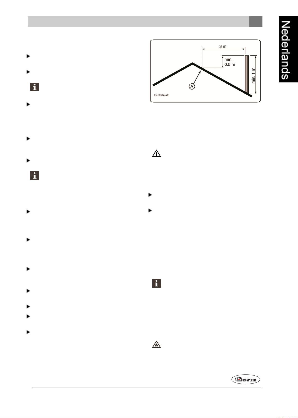
De schoorsteenmoet minimaal 4meter hoog zijn.
Als vuistregel geldt: 60cm boven de nok van het
dak.
Als de nok van het dak meer dan 3meter is verwijderdvan de schoorsteen: houd de maten aandie
in de volgende figuur zijn aangegeven. A = het
hoogste punt van het dak binnen een afstand van
3meter.
Een vuistregel is dat de luchttoevoer 5,5cm²/kW
moet zijn. Extra ventilatie is nodig:
Als het toestel in een ruimte staat die goed is geïsoleerd.
Als er mechanische ventilatie is, bv een centraal
afzuigsysteem of een afzuigkap in een open keuken.
U kunt voor extra ventilatie zorgen door een ventilatierooster in de buitenmuur te laten plaatsen.
Zorg dat andere luchtverbruikende apparaten (zoals
eenwasdroger, ander verwarmingstoestel of badkamerventilator) eeneigen buitenluchtaanvoer hebben, of zijn uitgeschakeld wanneer u het toestel
stookt.
U kunt het toestel ook aansluiten op buitenluchtaanvoer. Hiervooris eenaansluitset
meegeleverd. Extra ventilatie is dan niet nodig.
Vloer en wanden
De vloer waarop het toestel wordt geplaatst, moet voldoende draagvermogen hebben. Voorhet gewicht van
het toestel: zie de bijlage "Technische gegevens".
Bescherm een brandbare vloer door middel van
eenonbrandbare vloerplaat tegen warmte-
Wijzigingen op grond van technische verbeteringen voorbehouden
9
Page 10
uitstraling. Zie de bijlage "Afstand tot brand-
1
2
3
4
6
5
09-20021-150
09-20021-152
1
2
3
09-20021-154
baar materiaal".
Verwijder brandbaar materiaal zoals linoleum,
tapijt, enzovoorts onderde onbrandbare vloerplaat.
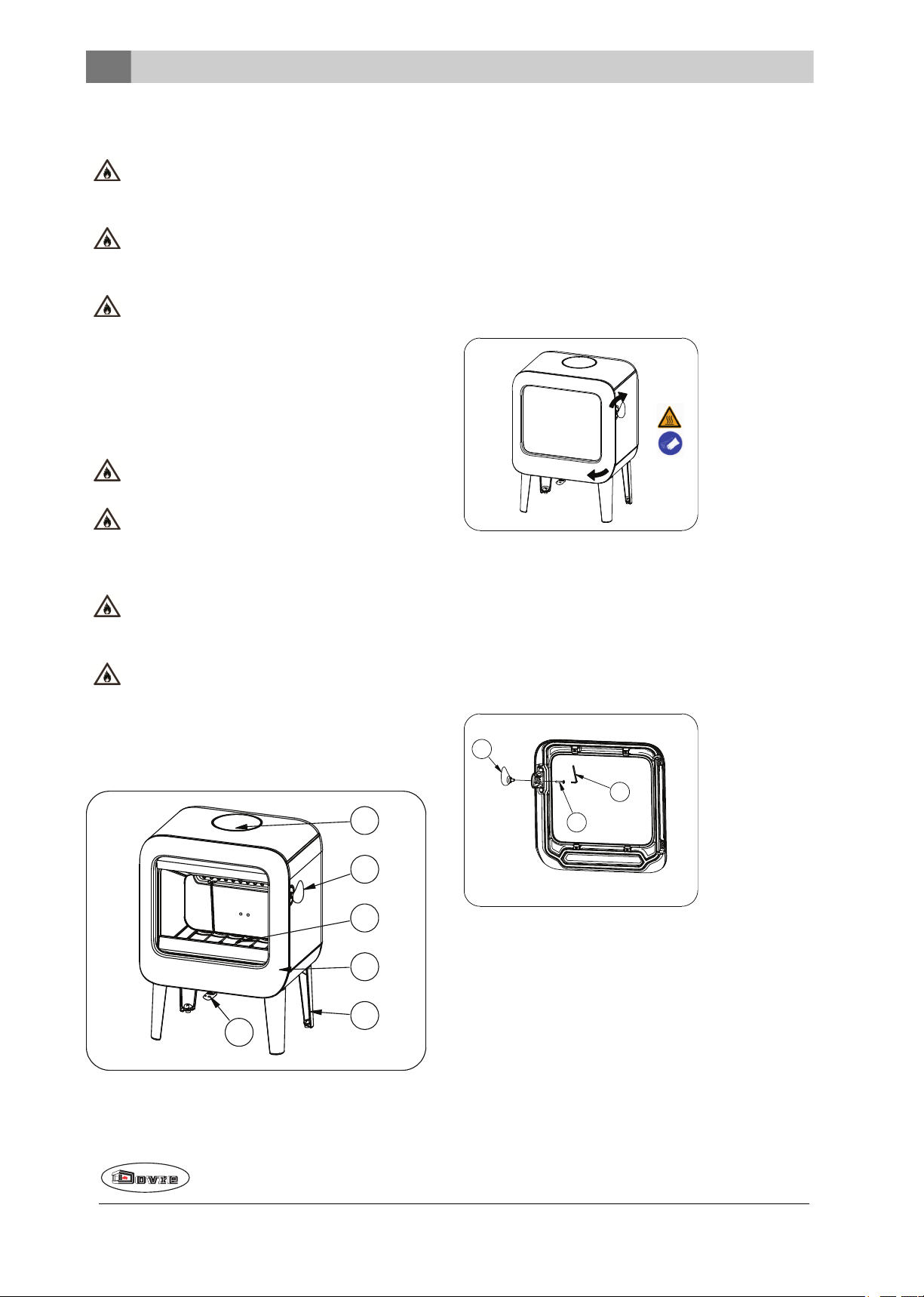
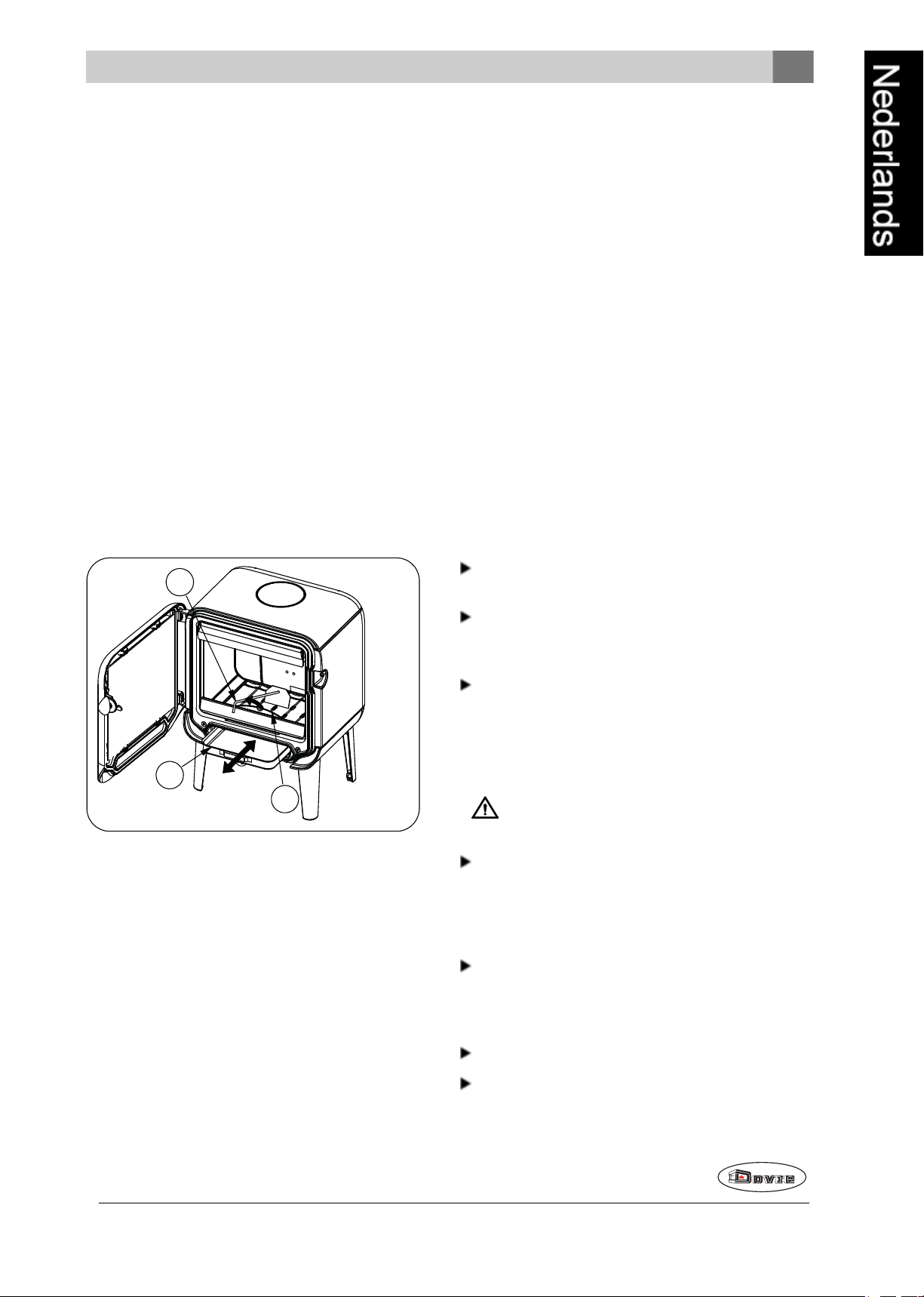
1. Aansluitkraag
2. Grendel
3. Stookbodem
4. Deur
Zorg voor voldoende afstand tussen het toestel
en brandbare materialen zoals houten wanden
en meubels.
Ook de aansluitbuis straalt warmte uit. Zorg
voor voldoende afstand of afscherming tussen
de aansluitbuis en brandbare materialen.
De vuistregel voor een enkelwandige buis is
eenafstand vandriemaal de diameter. Als een
bekledingsschelp rondde buis is aangebracht,
is een afstand van eenmaal de diameter toelaatbaar.
Een vloerkleed moet minimaal 80cm van het
vuur verwijderdzijn.
Bescherm een brandbare vloer voor de kachel
met behulp van een onbrandbare vloerplaat
tegen eventueel uitvallende assen. De vloerplaat moet voldoen aannationale normen.
Voor de afmetingen van de onbrandbare vloerplaat: zie de bijlage "Afstand tot brandbaar
materiaal".
Voor verdere eisen in verband met brandveiligheid: zie de bijlage "Afstand tot brandbaar
materiaal".
5. Poot
6. Luchtschuif
Deursluiting en koude hand
Het toestel wordt geleverd met de grendelknop gemonteerd. De deur wordt geopend door degrendelknop te
draaien in wijzer zin. Omdat de grendelknop tijdens
het gebruik warm wordt, is er een handschoen bijgeleverd die u kunt gebruiken als bescherming voor
uw hand. Tevens kan de grendelknop worden losgemaakt van het toestel en zodoende als "koude
hand" worden gebruikt.
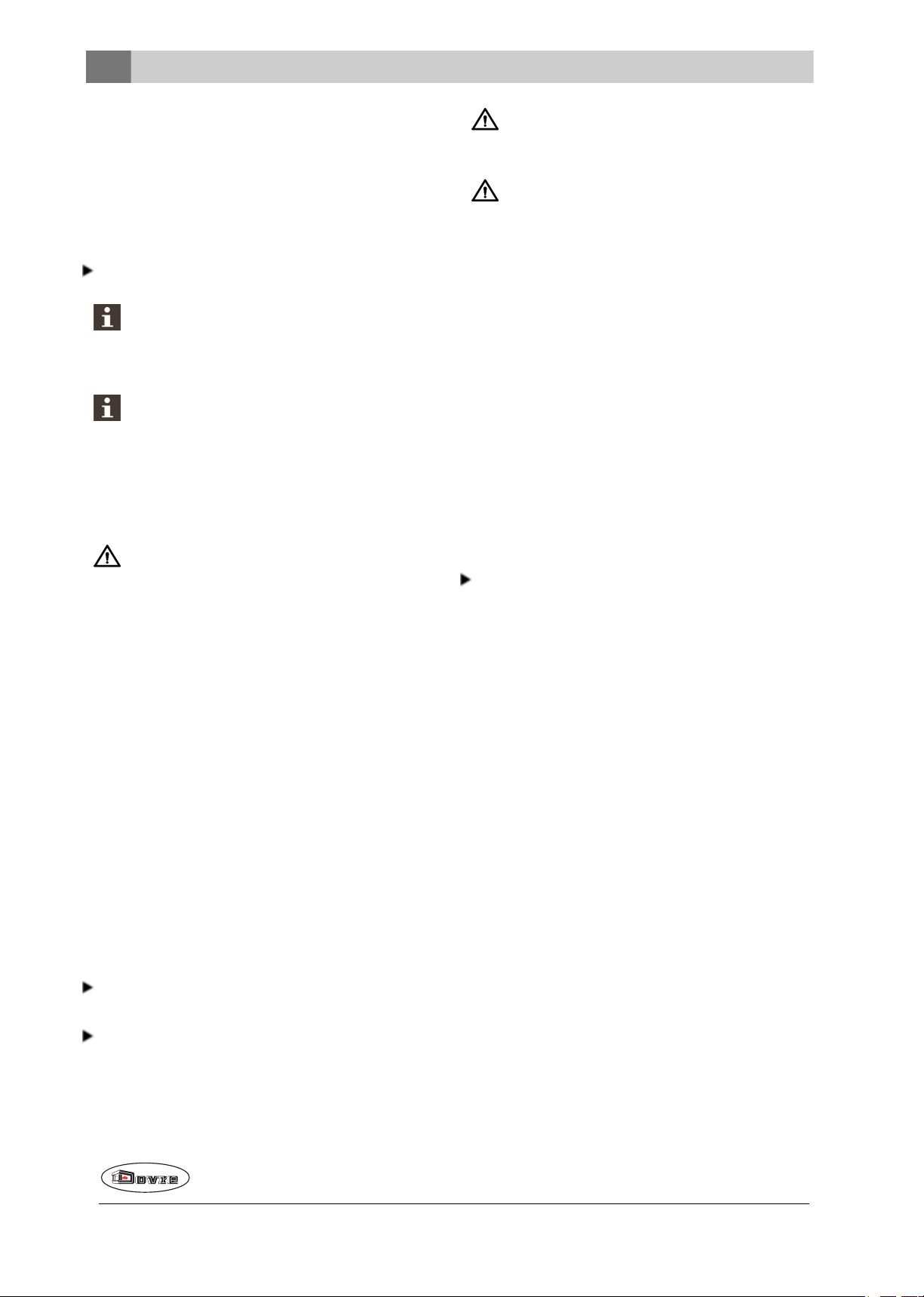
Productbeschrijving
1. Open de deurvan het toestel.
2. Verwijder de bout (2) door middel van een inbussleutel (3).
3. Verwijder de grendelknop (1) van de deur.
10
4. Bewaarde bout (2) indien u degrendelknop
opnieuw wenst te monteren.
Wijzigingen op grond van technische verbeteringen voorbehouden
Page 11
Installatie
1
2
3
4
09-20021-151
1
09-20021-156
09-20021-152
Algemene voorbereiding
Controleer het toestel onmiddellijk bij ontvangst op
(transport)schadeen eventuele andere gebreken.
Het toestel is aan de onderkant met schroeven op
de pallet gemonteerd.
Als u (transport)schade of gebreken hebt
geconstateerd, neem het toestel dan niet in
gebruik en stel de leverancier op de hoogte.
Verwijder de demontabele onderdelen (vuurvaste
binnenplaten, stookrooster, topplaat, aslade)uit
het toestel voordat u het toestel gaat installeren.
Door demontabele onderdelen te verwijderen,
kunt u het toestel gemakkelijker verplaatsen en
beschadiging voorkomen.
Let bij het verwijderen van demontabele onderdelen op hun oorspronkelijke positie, om ze
later weer op de juiste plaats te kunnen aanbrengen.
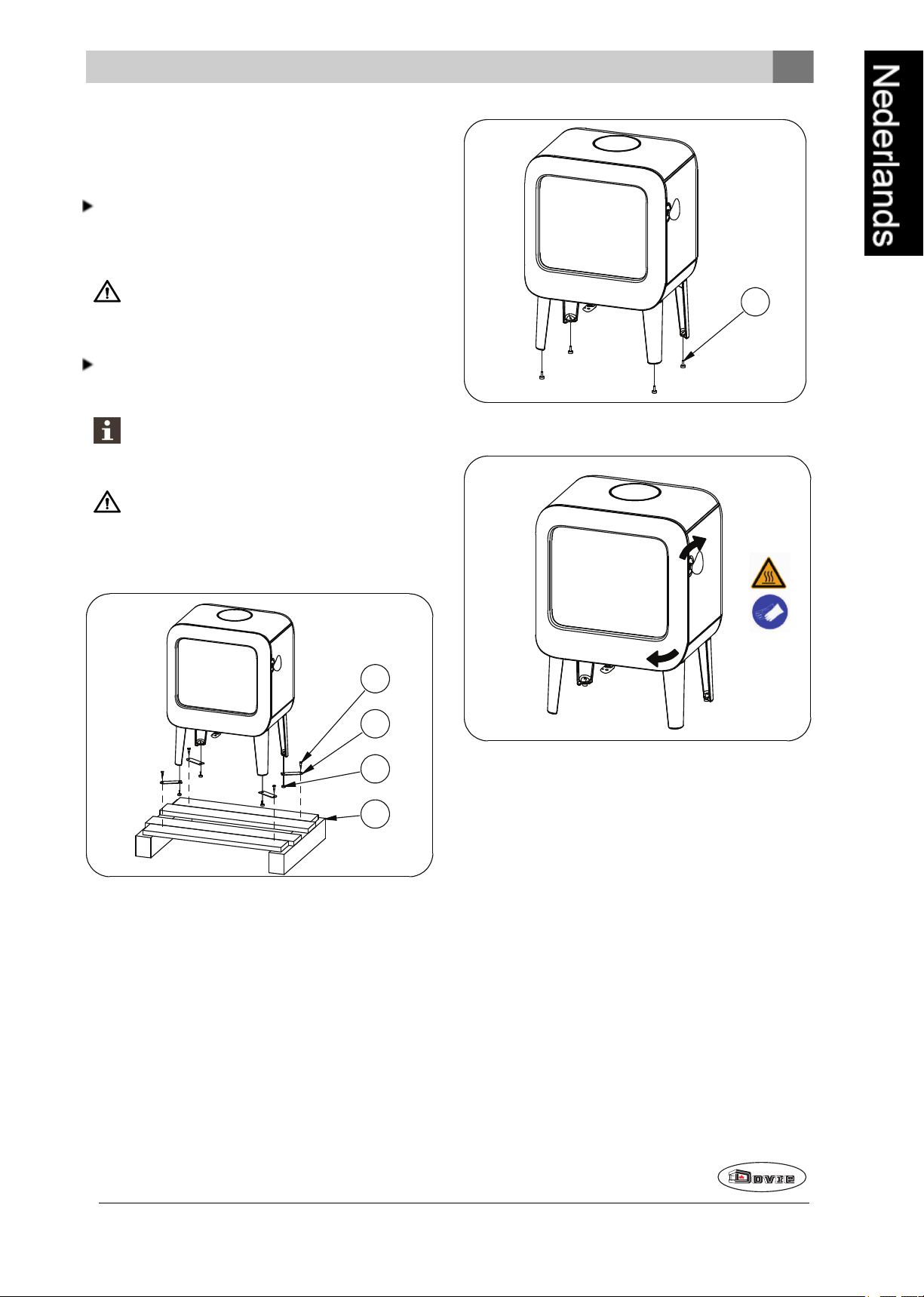
4. Open de deur; zie volgendefiguur.
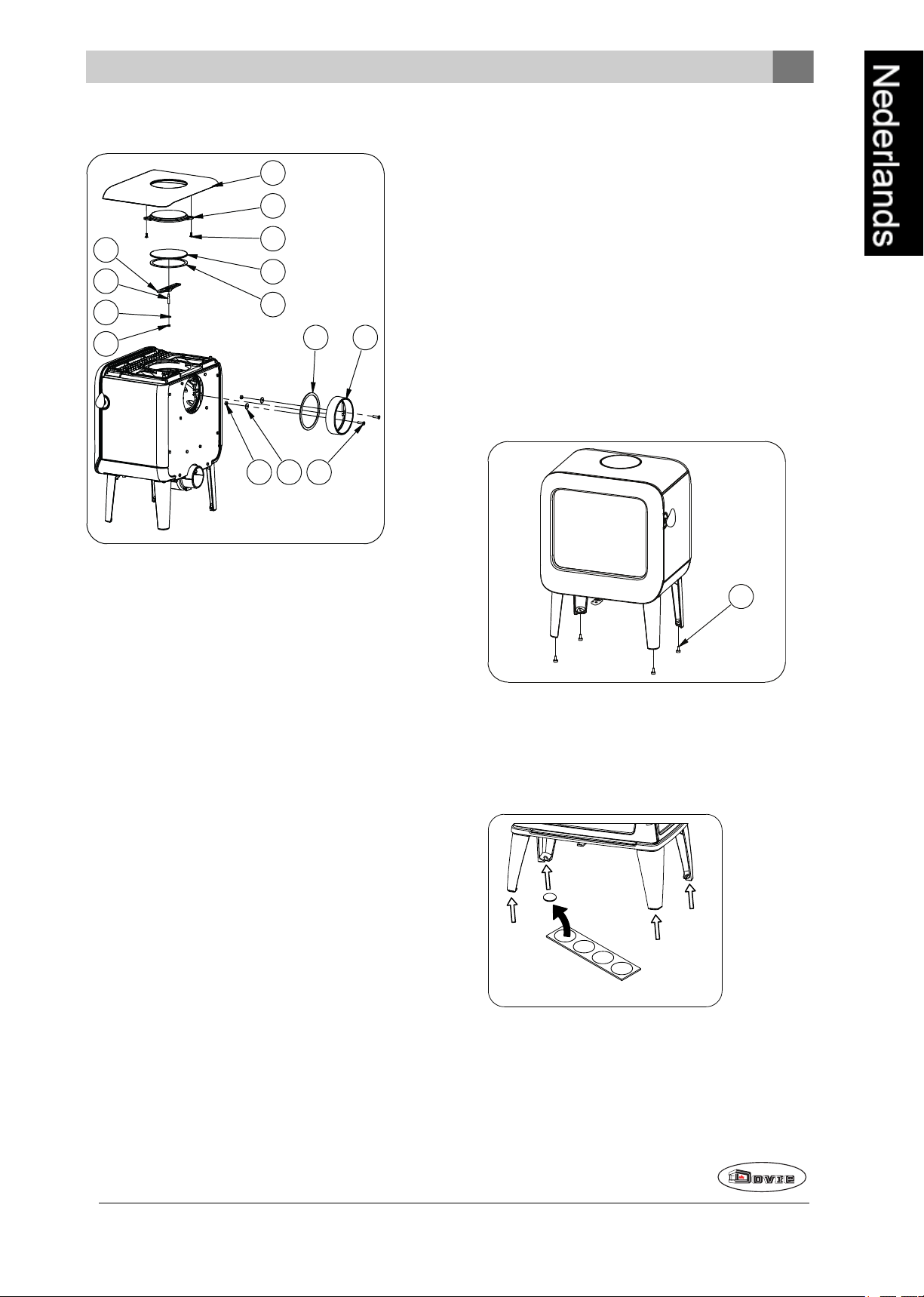
1. Verwijder het toestel van de pallet (4) doorde bouten (1) te verwijderen.
2. Verwijder de bevestigingsbeugels (2) doorde stelvoeten (3) uit te draaien.
3. Hermonteerde stelvoeten (3).
Wijzigingen op grond van technische verbeteringen voorbehouden
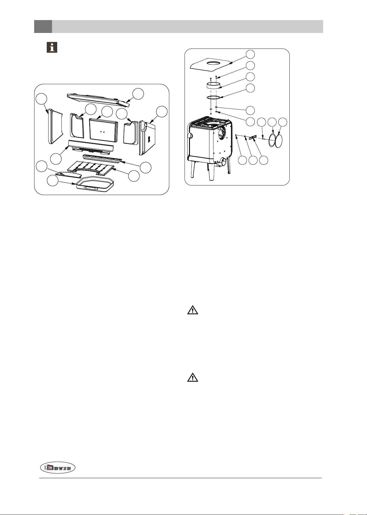
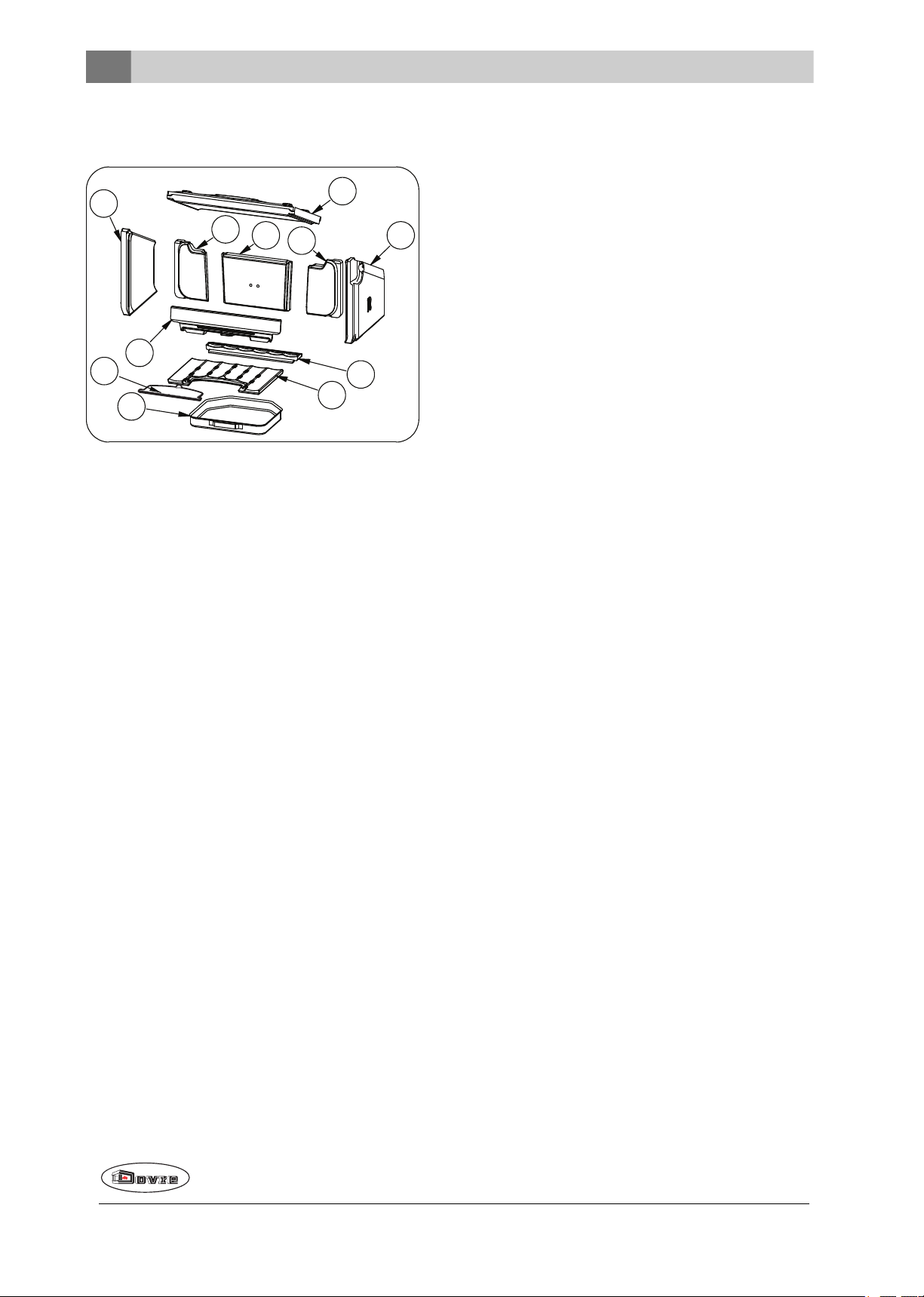
5. Verwijder de vuurvaste binnenplaten; zie volgende
figuur.
a. Til de vlamplaat (6) op aan de linkerzijde.
b. Verwijder de binnenplaat (4).
c. Til de vlamplaat (6) op aan de rechterzijde.
d. Verwijder de binnenplaat (5).
e. Verwijder de vlamplaat (6).
f. Verwijder binnenplaten 1, 2 en 3.
g. Verwijder de vuurkorf (8).
h. Verwijder het ontassingsluik (11).
i. Verwijder het rooster (9) en (7).
j. Verwijder de aslade(10).
11
Page 12
Vermiculiet binnenplaten zijn licht van
4
5
6
1
3
2
8
7
9
10
09-20021-153
11
1
4
9
2
3
6
7
13 12 11
10
8
09-20021-158
gewicht en bij levering meestal okerkleurig.
Zij isoleren de verbrandingskamer zodat de
verbranding beter is.
Uitneembare binnendelen
01 binnenplaat achter links
02 binnenplaat achter rechts
03 binnenplaat achter midden
04 binnenplaat links
05 binnenplaat rechts
06 vlamplaat
07 stookbodem achter
08 vuurkorf
09 stookbodem voor
10 aslade
11 ontassingsluik
Aansluiten op de achterzijde
Voor de aansluiting op deachterzijde moet de positie
van de aansluitkraag gewijzigd worden. De aansluitkraag is bevestigd met 2 moeren M8 (sleutel 13).
Ga als volgt te werk:
Demontage (zie vorige tekening)
1. Verwijder de vlamplaat.
2. Demonteer het afsluitdeksel (8) uit de achterwand,
door de moer (13)te lossen en klembeugel (12) te
verwijderen.
3. Verwijder afsluitdeksel (8) en deafdichting (9).
Schoorsteenaansluiting voorbereiden
Bij het aansluiten van het toestel op een schoorsteen
hebt u de keuze uit aansluiting aan de bovenzijde of
Controleer of het afdichtband op het contactvlak niet is beschadigd. Vervang het
afdichtband als dat wel het geval is.
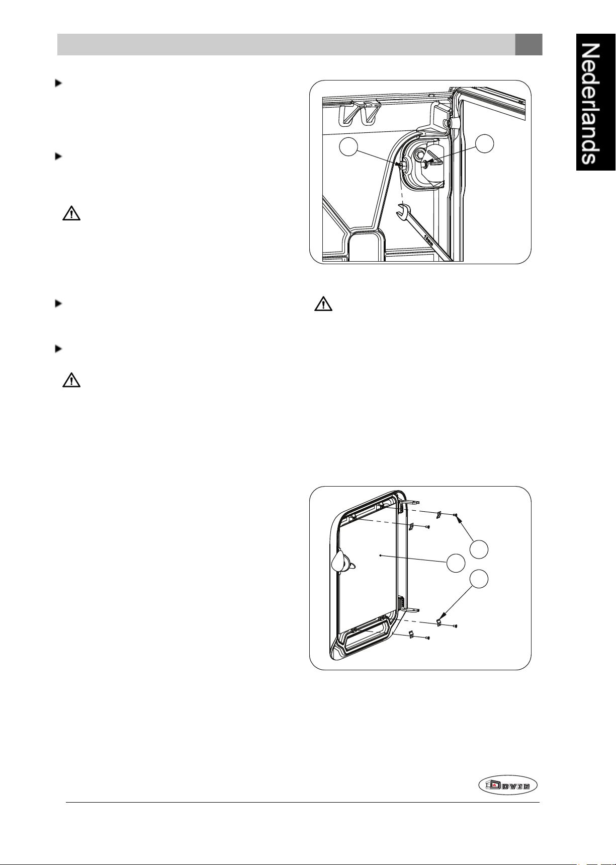
4. Demonteer deaansluitkraag (3) door de bouten (2)
te lossen.
aande achterzijde van het toestel.
5. Verwijder de aansluitkraag (3), de afdichting (4),
Aansluiten op de bovenzijde
Het toestel wordt standaard geleverdmet deaansluitkraag gemonteerd voor een aansluiting aan de
bovenzijde, zie volgende afbeelding.
12
de bevestigingsmaterialen (2, 6, 7).
Controleer of het afdichtband op het contactvlak niet is beschadigd. Vervang het
afdichtband als dat wel het geval is.
Wijzigingen op grond van technische verbeteringen voorbehouden
Page 13
Montage (zie tekening hierna)
1
2
3
4
5
6
7
9
8
15 14
12 11
10
09-20021-157
1
09-20021-156
09-20500-015
Buitenluchtaansluiting via de wand
1. Maak een aansluitgat in de wand (raadpleeg de bijlage"Afmetingen", voor de juiste positie van het
aansluitgat).
2. Sluit de luchtaanvoerbuis hermetisch af op de
muur.
Plaatsen en aansluiten
1. Zet het toestel op de juiste plaats, vlak en waterpas. Het toestel is uitgevoerd met stelvoetjes die
al op het toestel zijn gemonteerdof worden bijgeleverd. Gebruik deze stelvoetjes zodat het toestel perfect waterpas kan wordengesteld.
1. Verwijder de topplaat (1).
2. Monteer het bijgeleverdesierdeksel (2)met de
bevestigingsmaterialen (3).
3. Monteer het afsluitdeksel (4) ende afdichting (5)
met bevestigingsmaterialen (6, 7, 8, 9).
4. Plaats de toppplaat (1) met het gemonteerde sierdeksel (2) op het toestel.
5. Monteer deaansluitkraag (11), de afdichting (12)
met de bevestigingsmaterialen (10, 14, 15) op de
achterwand
2. Indien het toestel op een gladde ondergrond staat,
kunnen de vier anti-slip pads onder de stelvoeten
worden geplaatst om verschuiven van het toestel
te voorkomen, zie volgende afbeelding.
Buitenluchtaansluiting voorbereiden
Als het toestel wordt geplaatst in een ruimte die onvoldoende is geventileerd, kunt u de aansluitset voor het
aanvoeren van buitenlucht op het toestel aansluiten.
De luchtaanvoerbuis heeft een diameter van 100mm.
Bij toepassing van een gladde buis mag deze buis
maximaal 12meter lang zijn. Bij gebruik van hulpstukken zoals bochten moet u per hulpstuk de maximale lengte (12meter) met 1meter verminderen.
3. Sluit het toestel hermetisch aan opde schoorsteen.
Wijzigingen op grond van technische verbeteringen voorbehouden
13
Page 14
4. Bij buitenluchtaansluiting: sluit deaanvoer van bui-
09-20500-016
tenlucht aan op de aansluitset die op het toestel is
gemonteerd.
5. Plaats alle gedemonteerde onderdelen op de juiste
plaats terug in het toestel.
Laat het toestel nooit branden zonder de vuurvaste binnenplaten.
Het toestel is nu klaarvoorgebruik.
Gebruik
Eerste gebruik
Wanneer u het toestel voor het eerst gebruikt, stook
het dan enkele uren flink door. Hierdoor zal de hittebestendigelak uitharden. Hierbij kan wel wat rook
en geurhinder ontstaan. Zet eventueel in de ruimte
waar het toestel staat de ramen en deuren evenopen.
Brandstof
Dit toestel is alleen geschikt voor het stoken van
natuurlijk hout; gezaagd en gekloofd en voldoende
droog.
Gebruik geen andere brandstoffen, want die kunnen
leiden tot ernstige schade aan het toestel.
De volgende brandstoffen mag u niet gebruiken omdat
zij het milieu vervuilen, en omdat zij het toestel en de
schoorsteen sterk vervuilen waardoor schoorsteenbrand kan ontstaan:
Behandeld hout, zoals sloophout, geverfd hout,
geïmpregneerd hout, verduurzaamd hout, multiplex
en spaanplaat.
vochtpercentage van 60% en levert slechts 1,6
kWh per kg hout.
Zaag het hout op maat en klief het als het nog vers
is. Vers hout klieft gemakkelijker en gekloven hout
droogt beter. Bewaar het hout onder een afdek
waar de wind vrij spel heeft.
Gebruik geen nat hout. Nat hout geeft geen warmte
omdat alle energie gaat zitten in het verdampen
van vocht. Dit geeft veel rook en roetaanslag op de
deur van het toestel en in de schoorsteen. De
waterdamp condenseert in het toestel en kan langs
naden uit het toestel lekken en zwarte vlekken op
de vloer geven. De waterdamp kanook in de
schoorsteen condenseren en creosoot vormen.
Creosoot is zeer brandbaar enkan schoorsteenbrand veroorzaken.
Aanmaken
U kunt controleren of de schoorsteen voldoende trek
heeft door boven devlamplaat een prop krantenpapier
aante steken. Bij een koude schoorsteen is er vaak
onvoldoende trek in de schoorsteen en kan er rook in
de kamer komen. Doorhet toestel op de hier beschreven manier aan te maken, voorkomt u dit probleem.
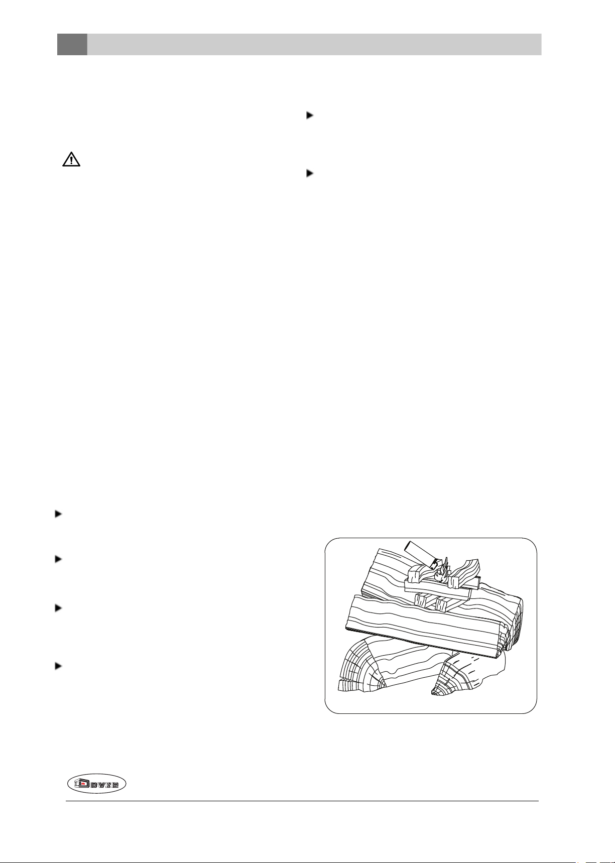
1. Stapel twee lagen middelgrote houtblokken kruislings op elkaar.
2. Stapel bovenop de houtblokken twee à drie lagen
aanmaakhoutjes kruislings op elkaar.
3. Legeen aanmaakblokje tussen de aanmaakhoutjes en steek het aanmaakblokje aan volgens de instructies op de verpakking.
Kunststof, oud papier en huishoudelijk afval.
Hout
Gebruik bij voorkeur hard loofhout zoals eik, beuk,
berk en fruitbomenhout. Dit hout brandt langzaam
met rustige vlammen. Naaldhout bevat meer hars,
brandt sneller en geeft meer vonken.
Gebruik gedroogd hout met een vochtpercentage
van maximaal 20%. Hiervoor moet het hout minstens 2 jaar zijn gedroogd. Hout met een vochtpercentage van 20% levert 4,2 kWh per kg hout.
Hout met een vochtpercentage van 15% levert 4,4
kWh per kg hout. Vers gekapt hout heeft een
14
Wijzigingen op grond van technische verbeteringen voorbehouden
Page 15
4. Sluit de deur van het toestel en zet de primaire
09-20021-155
A B C
09-20500-017
09-20500-018
luchtinlaat en de secundaire luchtinlaat van het toestel open; zie volgende figuur.
5. Laat het aanmaakvuurflink doorbranden totdat het
eengloeiend houtskoolbed is geworden. Hierna
kunt u eenvolgendevulling doen en het toestel
gaan regelen; zie de paragraaf "Stoken met hout".
Losse stapeling
Bij een losse stapeling verbrandt het hout vlug omdat
de zuurstof elk stuk hout gemakkelijk kan bereiken.
Gebruik een losse stapelingals u kort wilt stoken.
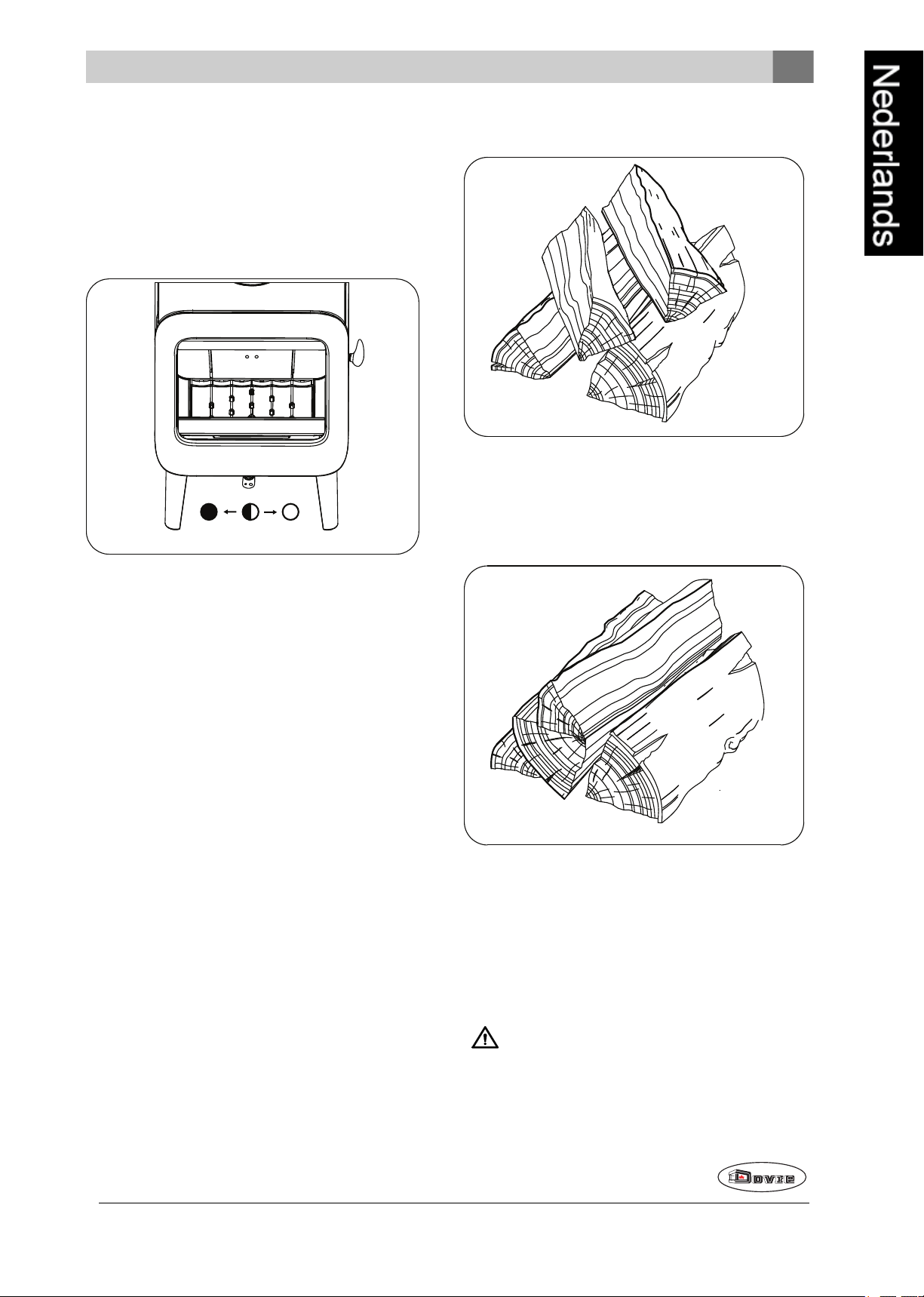
Compacte stapeling
C:
Primaire lucht open (tijdens aanmaken)
Secundairelucht open (glasspoeling)
Lucht voor naverbranding open
B:
Secundairelucht open (glasspoeling)
Lucht voor naverbranding open
A:
Lucht voor naverbranding open
(voor goede verbranding nooit helemaal sluiten)
Stoken met hout
Nadat u de instructies voor het aanmaken hebt
gevolgd:
1. Open langzaam de deur van het toestel.
2. Verdeel het houtskoolbed gelijkmatig over de
stookvloer.
3. Stapel enkele houtblokken op het houtskoolbed.
Bij een compacte stapeling verbrandt het hout langzamer omdat de zuurstof maar enkele stukken hout
kan bereiken. Gebruik een compacte stapelingals u
langer wilt stoken.
4. Sluit de deur van het toestel.
5. Sluit de primaire luchtinlaat en laat de secundaire
luchtinlaat openstaan.
Vul het toestel voor maximaal een derde.
Wijzigingen op grond van technische verbeteringen voorbehouden
15
Page 16
Maximale hoeveelheid hout
09-20021-155
A B C
09-20021-159
2
1
3
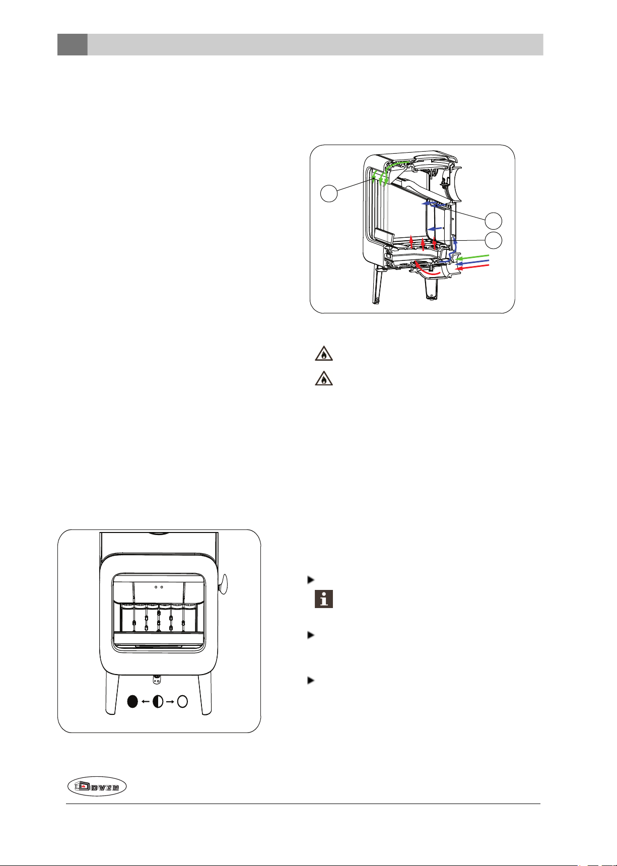
De secundaire lucht regelt de lucht voor het glas (airwash) (2).
Om continu te kunnen stoken tegen het nominalevermogen, moet er iedere 45 minuten hout worden bijgevuld. Als u de hoeveelheidhout per keer vermindert,
kunt u vaker bijvullen. Elke kachel is ontworpen om te
werken met een bepaalde maximale hoeveelheid
hout. Als u een grotere hoeveelheid hout gebruikt,
wordt de warmte-afgifte groter. Daardoor kande haard
overbelast raken en kunnener onderdelenworden
beschadigd.
Toegestanemaximale hoeveelheid brandstof voor
hout met een vochtpercentage van 15%:
l ROCK 7 KW heeft een maximale vulling van
1,5 kg hout per 45minuten.
l ROCK 9 KW heeft een maximale vulling van
1,5 kg hout per 45minuten.
Vul de verbrandingskamer voor maximaal één derde
en vul nooit hout boven de openingen voor secundaire
lucht.
Regeling verbrandingslucht
De achterwand heeft onder de vlamplaat permanente
luchtopeningen (3) die zorgenvoorde naverbranding.
Adviezen
Stook nooit met open deur.
Stook het toestel regelmatig flink door.
Het toestel heeft één luchtschuif die zowel de primaire
lucht als de secundaire lucht regelt. Als de luchtschuif
in positie C staat, is de primaire ensecundaire luchtinlaat open. Naarmate deluchtschuif verder wordt
dichtgedraaid, sluit de primaire luchtinlaat en daarna
de secundaire luchtinlaat. Als de luchtschuif geheel
gesloten in positie A staat, blijft een kleineluchtopening open om de naverbranding onderde vlamplaat te verzorgen.
Als u langdurig op lagestand stookt, kan zich
in de schoorsteen een afzetting vormen van
teer en creosoot. Teer encreosoot zijn zeer
brandbaar. Als de afzetting van deze stoffen te
groot wordt, kan bij eenplotselinge hogetemperatuur eenschoorsteenbrand ontstaan. Door
regelmatig flink doorstoken, verdwijnen eventuele afzettingen van teer en creosoot.
Daarnaast kan zich bij te laag stoken teerafzetten op de ruit en deurvan het toestel.
Bij een mildebuitentemperatuuris het dus
beter om het toestel een paar uur intens te
laten branden, dan lange tijd laag te stoken.
Regel de luchttoevoer met de luchtschuif.
De luchtinlaat belucht niet alleen het vuurmaar
ook het glas, zodat het glas niet snel vervuilt.
Zet de primaire luchtinlaat tijdelijk open als deluchttoevoer via de secundaireluchtinlaat onvoldoende
is of als u het vuurwilt aanwakkeren.
Regelmatig eenkleine hoeveelheid houtblokken bijvullen is beterdan veel houtblokken tegelijk.
De primaire lucht regelt de lucht onder het rooster (1).
16
Wijzigingen op grond van technische verbeteringen voorbehouden
Page 17
Doven van het vuur
2
1
3
09-20021-159
Nevel en mist
Vul geen brandstof bij enlaat de kachel gewoon uitgaan. Als een vuur wordt getemperd door de luchttoevoer te verminderen, komen schadelijke stoffen
vrij. Laat daarom het vuur vanzelf uitbranden. Houd
toezicht op het vuur totdat het goed is gedoofd. Als
het vuur volledig is gedoofd kunnen alle luchtschuiven
worden gesloten.
Ontassen
Na het stoken van hout blijft een relatief kleine hoeveelheid as over. Dit asbed is een goede isolator voor
de stookbodem en geeft een betere verbranding. Laat
daarom gerust een dun laagje as op de stookbodem liggen.
De luchttoevoerdoor de stookbodem mag echter niet
worden belemmerd ener mag zich geen as ophopen
achter een gietijzeren binnenplaat. Verwijder daarom
regelmatig de overtollige as.
Nevel en mist belemmeren de afvoer van rookgassen
door de schoorsteen. Rook kan neerslaan en stankoverlast geven. Als het niet echt nodig is, kunt u bij
nevel en mist beter niet stoken.
Eventuele problemen
Raadpleeg de bijlage "Diagnoseschema" om eventuele problemenbij het gebruik van het toestel op te
lossen.
Onderhoud
Volg deonderhoudsinstructies in dit hoofdstuk om het
toestel in goede staat te houden.
Schoorsteen
In veel landen bent u wettelijk verplicht de schoorsteen te laten controleren en onderhouden.
Aan het begin vanhet stookseizoen: laat de schoorsteen vegen door een erkend schoorsteenveger.
1. Open de deurvan het toestel.
2. Gebruik het trekschepje om het asluikje (1) te ope-
nen.
3. Gebruik het trekschepje om deovertollige assen
door het rooster in de aslade te schrapen.
4. Verwijder de aslade (3) met behulp vande bij-
geleverde handschoen en leeg de aslade.
5. Plaats de aslade terug en sluit de deur van het toe-
stel.
Tijdens het stookseizoen en nadat de schoorsteen
lange tijd niet is gebruikt: laat de schoorsteen controleren op roet.
Na afloop vanhet stookseizoen: sluit de schoorsteen af met eenprop krantenpapier.
Schoonmaken en ander regelmatig onderhoud
Maak het toestel niet schoon wanneer het nog
warm is.
Maak de buitenkant van het toestel schoon met
eendroge niet pluizende doek.
Na afloop vanhet stookseizoenkunt u de binnenkant
van het toestel goed schoonmaken:
Verwijder eventueel eerst de vuurvaste binnenplaten. Zie het hoofdstuk "Installatie" voor
instructies voor het verwijderen en aanbrengenvan
binnenplaten.
Maak eventueel de luchtaanvoerkanalen schoon.
Wijzigingen op grond van technische verbeteringen voorbehouden
Verwijder de vlamplaat boven in het toestel en
maak deze schoon.
17
Page 18
Vuurvaste binnenplaten controleren
De vuurvaste binnenplatenzijn verbruiksonderdelen
die aan slijtage onderhevig zijn. Vermiculiet binnenplaten zijn kwetsbaar. Stoot niet met houtblokken
tegen de binnenplaten. Controleer debinnenplaten
regelmatig en vervang ze indien nodig.
Zie het hoofdstuk "Installatie" voor instructies voor
het verwijderenen aanbrengen van binnenplaten.
De isolerende vermiculiet of chamotte binnenplaten kunnen haarscheuren gaan vertonen, maar dat heeft geen nadeligeffect op
hunwerking.
Gietijzeren binnenplaten gaan langmee als u
regelmatig as verwijdert die zich mogelijk
erachter ophoopt. Als opgehoopte as achter
eengietijzeren plaat niet wordt verwijderd, kan
de plaat de warmte niet meerafgeven aan de
omgeving enkan deplaat vervormen of scheuren.
Laat het toestel nooit branden zonder de vuurvaste binnenplaten.
Glas schoonmaken
Goed schoongemaakt glas neemt minder snel vuil op.
Ga als volgt te werk:
Als het glas van het toestel is gebroken of
gebarsten, moet dit glas wordenvervangen
voordat u het toestel opnieuw in gebruik neemt.
Voorkom dat kachelruitreinigertussen het glas
en de gietijzeren deur loopt.
Onderhoud geëmailleerde kachel
Reinig het toestel nooit als het nogwarm is. Het reinigen van het geëmailleerde oppervlak van de kachel
kunt u het beste doen met zachte groene zeepen
lauw water. Gebruik zo min mogelijk water, wrijf het
oppervlak goed droog en voorkom roestvorming.
Gebruik nooit staalwol of een anderschuurmiddel. Zet
nooit een waterketel direct op een geëmailleerde
kachel; gebruik een onderzetter en voorkom beschadigingen. Let erop dat er geenagressieve zureproducten op geëmailleerde onderdelen komen.
Smeren
Hoewel gietijzer enigszins zelfsmerend is, moet u
bewegende delen toch regelmatig smeren.
Smeerde bewegende delen (zoals geleidersystemen, scharnierpennen, grendels en luchtschuiven) met hittevast vet dat verkrijgbaaris bij
de vakhandel.
Lakbeschadigingen bijwerken
1. Verwijder stof en loszittend roet met een droge
doek.
2. Maak het glas schoon met kachelruitenreiniger:
a. Breng kachelruitenreiniger aan op een keu-
kenspons, wrijf het gehele glasoppervlak in en
laat even inwerken.
b. Verwijder het vuil met een vochtige doek of
keukenpapier.
3. Maak het glas nogmaals schoon met een gewoon
glasreinigingsproduct.
4. Wrijf het glas schoon met een droge doek of keu-
kenpapier.
Gebruik geen schurende of bijtende producten om
het glas schoonte maken.
Gebruik schoonmaakhandschoenen om uw handente beschermen.
Kleine lakbeschadigingen kunt u bijwerken met een
spuitbus speciale hittebestendige lak die verkrijgbaar
is bij uw leverancier.
Het geëmailleerde oppervlak bijwerken
Emailleren is een artisanaal proces dat maakt dat er
kleine kleurverschillenen beschadigingen op het toestel kunnen voorkomen. De toestellen ondergaan in
de fabriek eenvisuele controle, dat wil zeggen, de controleur kijkt op een afstand van 1 meter gedurende 10
seconden naar het oppervlak.
Eventuele beschadigingen die danniet opvallen wordenals OK beschouwd. Bij het toestel is eenspeciale
hittebestendigelak meegeleverd waarmee kleine
(transport) beschadigingen kunnenworden bijgewerkt.
Breng de hittebestendige lak in dunne laagjes aanen
laat het goed drogen voordat het toestel in gebruik
genomen wordt.
18
Wijzigingen op grond van technische verbeteringen voorbehouden
Page 19
Sommigekleuren email zijn gevoelig voor ver-
1
2
09-20021-161
1
2
3
09-20021-162
andering van temperatuur. Hierdoorkan het voorkomen dat de kleur verandert tijdens het gebruik
van het toestel. Als het toestel is afgekoeld keert
de oorspronkelijke kleur van het email terug.
Als geëmailleerde oppervlakken zeer heet worden
kunnen er haarscheurtjes ontstaan. Dit is eennormaal verschijnsel en heeft geen invloed ophet functioneren vande kachel.
Zorg dat de kachel niet wordt overbelast. Bij
overbelasting wordt de oppervlaktetemperatuur
extreem hoog en kan er blijvende schade aan
het email ontstaan.
Afdichting controleren
Controleer of het afdichtingskoord van de deur nog
goed afsluit. Afdichtkoord verslijt en moet tijdig wordenvervangen.
Controleer het toestel op luchtlekken. Kit eventuele
kieren dicht met kachelkit.
Laat de kit goed uitharden voordat u het toestel
aanmaakt, anders blaast het vocht in dekit op
en ontstaat opnieuw een lek.
Sluiting deur bijstellen
Controleer of de deurgoed sluit. Indien nodig kan de
sluiting van de deur stakker of losser ingesteld worden
door de afstand van de sluitnok tot de deur te wijzigen.
Ga als volgt te werk:
1. Open de deur.
2. Verwijder de rechtse vlamplaat.
3. Los moer (1) aande binnenzijde vanhet toestel.
Glas vervangen
Als het glas van het toestel is gebroken of
gebarsten, moet dit glas wordenvervangen
voordat u het toestel opnieuw in gebruik neemt.
Ga als volgt te werk:
1. Schroef de vier glasbevestigingen met onderdelen
(1)en (2) los en verwijder het glas (3), zie volgende
figuur.
2. Controleer de glasafdichting en breng indien nodig
eennieuw afdichtkoord aan.
3. Plaats het nieuwe glas in de sponning en schroef
de glasbevestigingen vast.
4. Stel aan de binnenzijdede sluitnok (2) bij met
behulp van een inbussleutel.
5. Zet moer(1)terug vast.
6. Sluit de deur.
Wijzigingen op grond van technische verbeteringen voorbehouden
19
Page 20
Wisselstukken ROCK
4
5
6
1
3
2
8
7
9
10
09-20021-153
11
ROCK 350
Pos. Artikelnr. Omschrijving Aantal
01 70.77608.000 binnenplaat ach-
terzijde links
02 70.77609.000 binnenplaat ach-
terzijde rechts
03 70.77610.000 binnenplaat ach-
terzijde midden
04 70.77606.000 binnenplaat zijkant
links
05 70.77607.000 binnenplaat zijkant
rechts
06 70.77611.000 vlamplaat 1
07 70.56335.021 stookbodem achter 1
08 70.77471.021 vuurkorf 1
09 70.66578.021 stookbodem voor 1
10 70.05216.000 aslade 1
11 70.05407.021 asluik 1
1
1
1
1
1
02 70.77614.000 binnenplaat ach-
terzijde rechts
03 70.77610.000 binnenplaat ach-
terzijde midden
04 70.77606.000 binnenplaat zijkant
links
05 70.77607.000 binnenplaat zijkant
rechts
06 70.77612.000 vlamplaat 1
07 70.56335.021 stookbodem achter 1
08 70.77476.021 vuurkorf 1
09 70.66578.021 stookbodem voor 1
10 70.05216.000 aslade 1
11 70.05407.021 asluik 1
70.26400.000 glas
70.26101.041 servicekit glasbevestiging
70.79870.000 servicekit koord 6mm
70.79869.000 servicekit koord 8mm
70.79868.000 servicekit band zelfklevend
1
1
1
1
70.26396.000 glas
70.26101.041 servicekit glasbevestiging
70.79870.000 servicekit koord 6mm
70.79869.000 servicekit koord 8mm
70.79868.000 servicekit band zelfklevend
ROCK 500
Pos. Artikelnr. Omschrijving Aantal
01 70.77613.000 binnenplaat ach-
20
terzijde links
1
Wijzigingen op grond van technische verbeteringen voorbehouden
Page 21

Bijlage 1: Technische gegevens
Model ROCK 350
Nominaal vermogen 7 kW
Schoorsteenaansluiting(diameter) 150 mm
Gewicht 110kg
Aanbevolenbrandstof Hout
Kenmerk brandstof, max. lengte 35 cm
Massadebiet van rookgassen 5,2 g/s
Rookgastemperatuurgemeten in de meetsectie 269°C
Temperatuur gemeten aande uitgang van het toestel 274 °C
Minimum trek 12 Pa
CO-emissie (13%O2)
NOx-emissie (13% O2)
CnHm-emissie (13%O2)
Stofemissie 34,6 mg/Nm³
Stofemissie volgens NS3058-NS3059 4,17 gr/kg
Rendement 80 %
0,10 %
90 mg/Nm³
96 mg/Nm³
Wijzigingen op grond van technische verbeteringen voorbehouden
21
Page 22

Model ROCK 500
Nominaal vermogen 9 kW
Schoorsteenaansluiting(diameter) 150 mm
Gewicht 150kg
Aanbevolenbrandstof Hout
Kenmerk brandstof, max. lengte 50 cm
Massadebiet van rookgassen 9,3 g/s
Rookgastemperatuurgemeten in de meetsectie 240°C
Temperatuur gemeten aande uitgang van het toestel 288 °C
Minimum trek 12 Pa
CO-emissie (13%O2)
NOx-emissie (13% O2)
CnHm-emissie (13%O2)
0,10 %
139mg/Nm³
92 mg/Nm³
Stofemissie 29 mg/Nm³
Stofemissie volgens NS3058-NS3059 - gr/kg
Rendement 80 %
22
Wijzigingen op grond van technische verbeteringen voorbehouden
Page 23
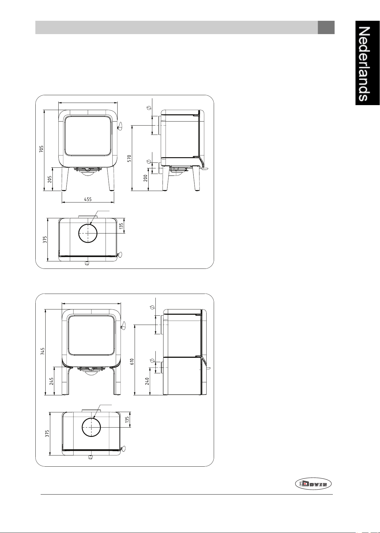
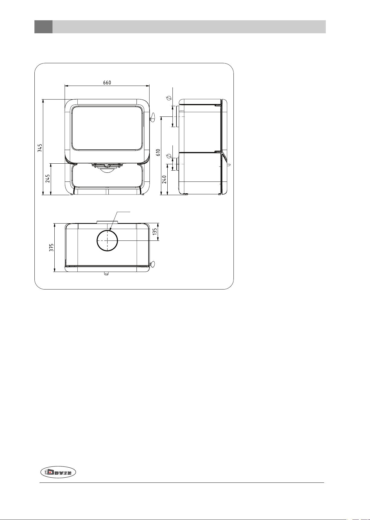
Bijlage 2: Afmetingen
510
100 150
ø150
09-2021-166
510
100 150
ø150
09-20021-165
ROCK 350
ROCK 350 TB
Wijzigingen op grond van technische verbeteringen voorbehouden
23
Page 24
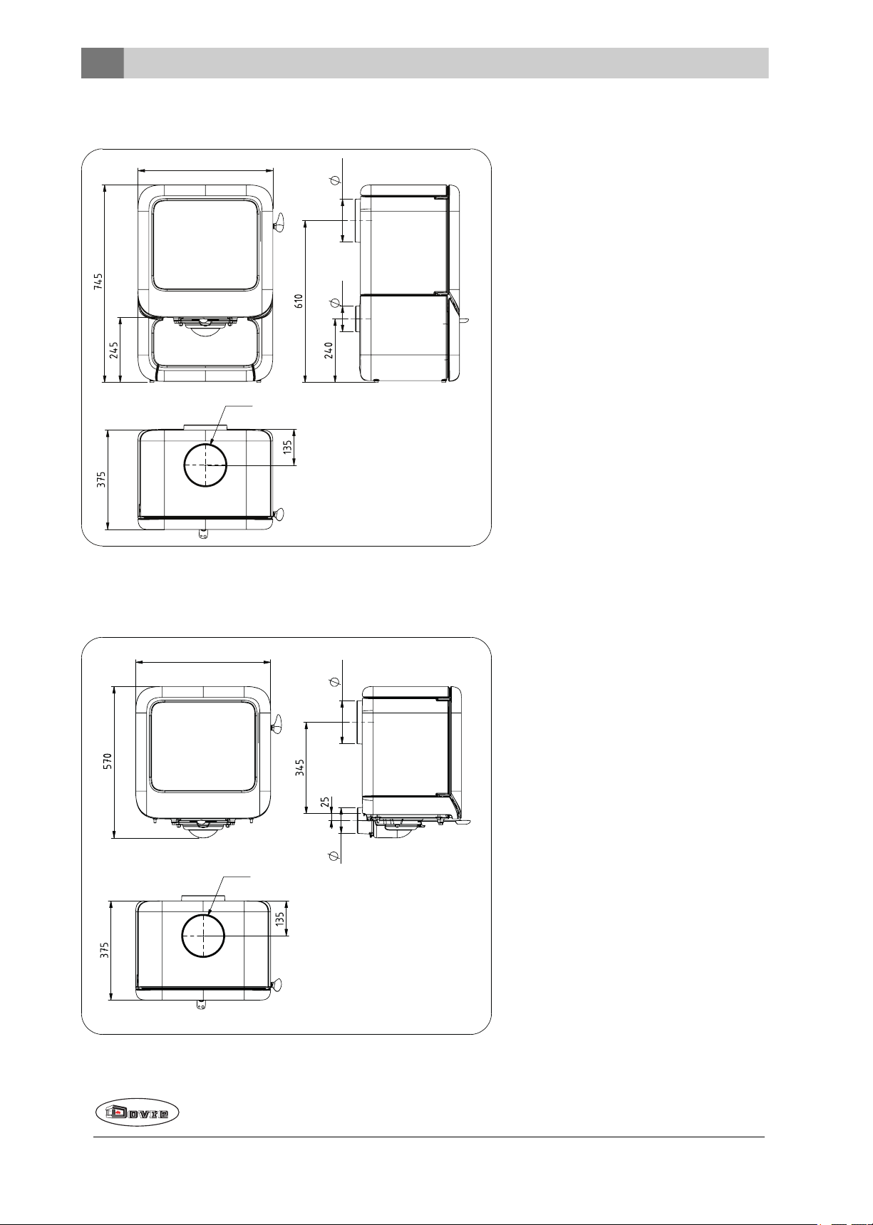
ROCK 350 WB
510
100 150
ø150
09-20021-165
510
100
150
ø150
09-20021-164
ROCK 350H
24
Wijzigingen op grond van technische verbeteringen voorbehouden
Page 25

ROCK 500
100 150
ø150
09-20021-171
Wijzigingen op grond van technische verbeteringen voorbehouden
25
Page 26
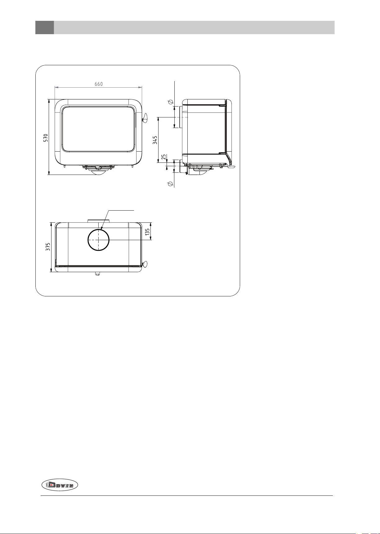
ROCK 500 H
100
150 int.
ø150 int.
09-20021-168
26
Wijzigingen op grond van technische verbeteringen voorbehouden
Page 27
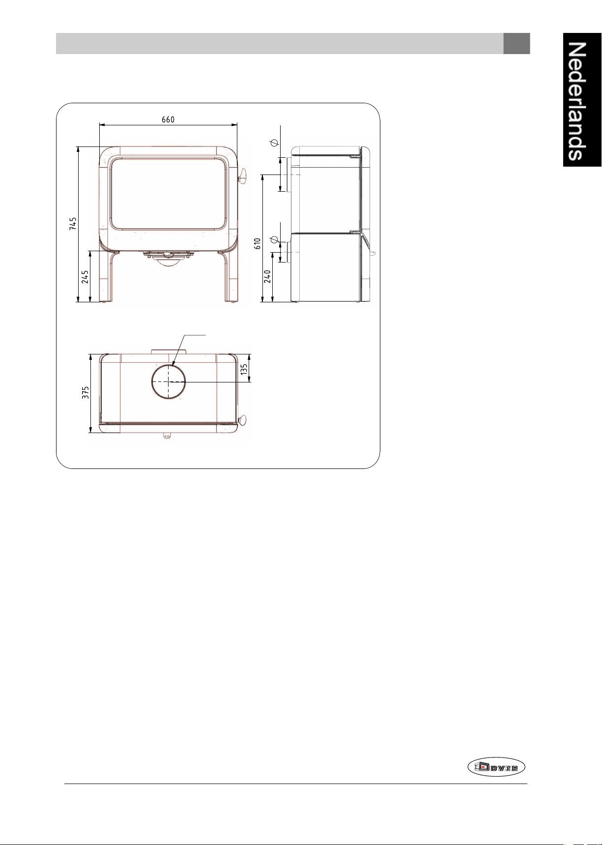
ROCK 500 TB
100 150
ø150
09-20021-169
Wijzigingen op grond van technische verbeteringen voorbehouden
27
Page 28
ROCK500 WB
100 150
ø150
09-20021-170
28
Wijzigingen op grond van technische verbeteringen voorbehouden
Page 29
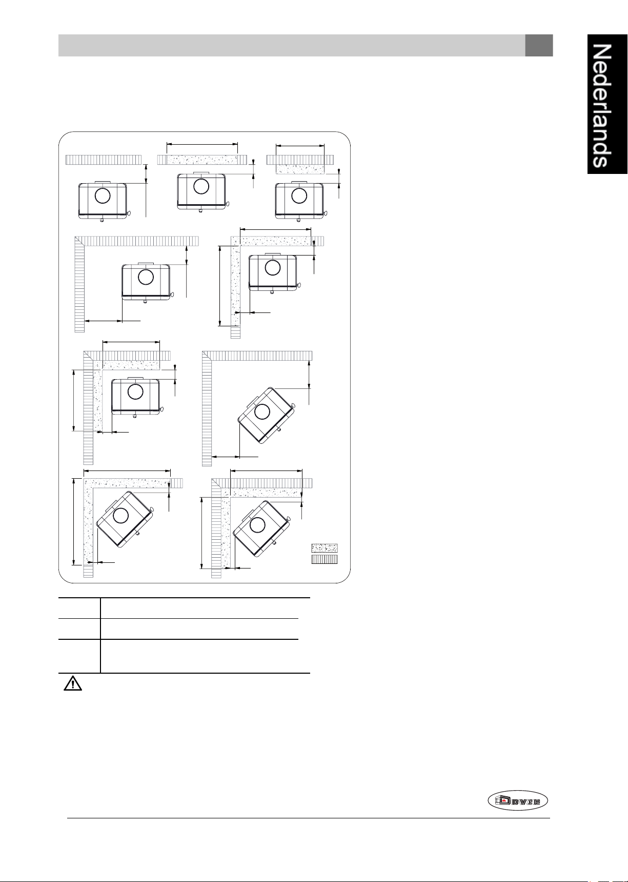
Bijlage 3: Afstand tot brandbaar materiaal
200**/100*
50
50
400
200**/100*
150
50
50
200
200
20
20
20
20
150
900
820
850
930
800
710
870
870
740
740
09-20021-167
2
1
ROCK 350 - Minimale afstanden in millimeters
1 Brandbaar materiaal
2 Onbrandbaar materiaal 100 mm
* met hitteschild en geïsoleerde buis
** zonder hitteschild met geïsoleerde buis
Let op! Om de toevoer van verbrandingslucht te garanderenmoet, wanneer er geen buitenluchtaansluiting
is voorzien, de afstand van deaansluitkraag voor de buitenlucht tot de muur minimaal 20 mm zijn. In voorkomende gevallen kan de aansluitkraaggedemonteerd worden.
Wijzigingen op grond van technische verbeteringen voorbehouden
29
Page 30
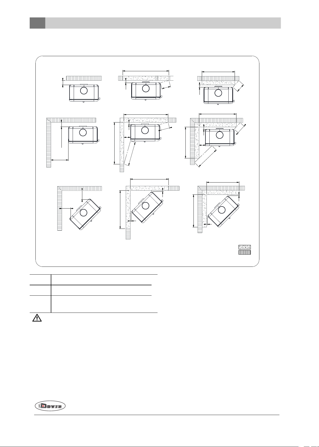
ROCK 500 - Minimale afstanden in millimeters
*100/**200
50
50
400
150
200
200
*100/**200
50
200
550
1050
750
1005
950
09-20021-202
150
50
550
200
845
710
200
200
20
20
870
870
20
20
740
740
2
1
1 Brandbaar materiaal
2 Onbrandbaar materiaal 100 mm
* met hitteschild en geïsoleerde buis
** zonder hitteschild met geïsoleerde buis
Let op! Om de toevoer van verbrandingslucht te garanderenmoet, wanneer er geen buitenluchtaansluiting
is voorzien, de afstand van deaansluitkraag voor de buitenlucht tot de muur minimaal 20 mm zijn. In voorkomende gevallen kan de aansluitkraaggedemonteerd worden.
30
Wijzigingen op grond van technische verbeteringen voorbehouden
Page 31

ROCK - Afmetingen onbrandbare vloerplaat
B B
A
09-20021-163
Minimale afmetingen onbrandbare vloerplaat
A (mm) B (mm)
Din 18891 500 300
Duitsland 500 300
Finland 400 100
Noorwegen 300 5
Wijzigingen op grond van technische verbeteringen voorbehouden
31
Page 32

Bijlage 4: Diagnoseschema
Probleem
Hout wil niet doorbranden
Geeft onvoldoende warmte
Rookterugslag tijdens het bijvullen
Toestel brandt te hevig, niet goed regelbaar
Aanslag op het glas
mogelijke oorzaak mogelijke oplossing
Een koude schoorsteen creëert vaak onvoldoende trek. Volg de
Onvoldoende trek
Hout te vochtig Gebruik hout met maximaal20% vocht.
instructiesvoor het aanmaken in het hoofdstuk "Gebruik"; open een
raam.
Afmetingen hout te groot
Stapeling hout niet correct
Werking van de schoorsteen onvoldoende
Uitmonding van de schoorsteen niet correct
Instelling van de luchtinlaten niet correct Open de luchtinlaten volledig.
Aansluiting van het toestel met de schoorsteen niet correct
Onderdruk in de ruimte waar het toestel
isgeplaatst
Onvoldoende toevoer van verse lucht
Ongunstigeweersomstandigheden? Inversie(omgekeerde luchtstroom inde schoorsteen door hoge buitentemperatuur), extreme
windsnelheden
Gebruik kleine stukjes aanmaakhout. Gebruikgekloven houtblokken
met een omtrek van maximaal 30 cm.
Stapel het hout zodanigdat er voldoende luchttussen de houtblokken kan stromen (losse stapeling, zie "Stoken met hout").
Controleer of de schoorsteen aan devoorwaarden voldoet: minimaal 4 meter hoog, juiste diameter, goed geïsoleerd, gladde binnenzijde,niet te veel bochten, geen obstructies in de schoorsteen
(vogelnest, te veel roetafzetting), hermetisch dicht (geen kieren).
Voldoende hoog boven het dakvlak,geen obstructiesin de nabijheid.
Aansluiting moet hermetischdicht zijn.
Zet afzuigsystemen uit.
Zorg voor voldoende luchttoevoer, maak desnoods gebruik van de
buitenluchtaansluiting.
Bijinversieis gebruik van het toestelaf te raden. Plaatsdesnoods
een trekkende kap op de schoorsteen.
32
Tocht inde woonkamer
Vlammen raken het glas
Toestel lekt lucht Controleer de afdichtingen van de deur en de naden van het toestel.
Voorkom tocht in de woonkamer; plaatshet toestelniet in de nabijheid van een deur of verwarmingsluchtkanalen.
Zorg dat het hout niette dicht tegen hetglas ligt. Schuif de primaire
luchtinlaat verder dicht.
Wijzigingen op grond van technische verbeteringen voorbehouden
Page 33

Index
D
A
Aanmaakhout 32
Aanmaakvuur 14
Aansluiten
afmetingen 23
Aansluitenop buitenluchtaanvoer 13
Aansluitenop schoorsteen
aanachterzijde 12
aanbovenzijde 12
Aansluitkraag schoorsteenaansluiting 12
Aansteken 14
Afdichtingskoord van deur 19
Afmetingen 23
Afwerklaag, onderhoud 18
As verwijderen 17
Aslade
openen 17
B
Beluchtingvan het vuur 16
Bijvullen van brandstof 16
rookterugslag 32
Binnenplaten
vermiculite 12
Binnenplaten, vuurvaste
verwijderen 11
Brandbaar materiaal
afstand tot 29
Brandstof
benodigde hoeveelheid 17
bijvullen 15-16
geschikte 14
hout 14
ongeschikte 14
Brandveiligheid
afstand tot brandbaar materiaal 29
meubels 9
vloer 9
wanden 9
Buitenluchtaanvoer 9, 13
aansluiting op 13
C
Creosoot 16
Demontabele onderdelen 11
Deur
afdichtingskoord 19
bijstellen 19
openen 11
sluiting 19
sluitnok 19
Draagvermogen van vloer 9
Drogen van hout 14
E
Email
onderhoud 18
G
Geschikte brandstof 14
Gewicht 21-22
Gietijzeren binnenplaten 11
Gladde ondergrond 13
Glas
aanslag 32
beschadigd 19
gebarsten 19
schoonmaken 18
vervangen 19
H
Hout 14
bewaren 14
drogen 14
geschikte soort 14
nat 14
wil niet doorbranden 32
Houtblokken stapelen 15
K
Kachelruitenreiniger 18
Kap opde schoorsteen 9
Kieren in toestel 19
L
Lak 14
Luchtinlaten 15
Luchtlek 19
Luchttoevoer regelen 16
Wijzigingen op grond van technische verbeteringen voorbehouden
33
Page 34

M
schoonmaken 18
Mist, niet stoken 17
Muren
brandveiligheid 9
N
Naaldhout 14
Nat hout 14
Nevel, niet stoken 17
Nominaal vermogen 17, 21-22
O
Onderdelen, demontabele 11
Ondergrond
glad 13
Onderhoud
afdichting 19
email 18
glas schoonmaken 18
schoorsteen 17
smeren 18
toestel schoonmaken 17
vuurvaste binnenplaten 18
Ongeschikte brandstof 14
Ontassen 17
Openen
aslade 17
deur 11
Opslagvan hout 14
P
Plaatsen
afmetingen 23
anti-slip 13
Primaire luchtinlaat 15
Problemen oplossen 17, 32
S
Schade 11
Scharnier
stellen 19
Schoonmaken
glas 18
toestel 17
Schoorsteen
aansluitdiameter 21-22
aansluiting op 13
hoogte 9
onderhoud 17
voorwaarden 9
Schoorsteenaansluiting
achterzijde 12
bovenzijde 12
Schoorsteenbrand voorkomen 16
Schoorsteenkap 9
Secundaireluchtinlaat 15
Sluitnok
opvulplaatje 19
Smeren 18
Stof-emissie 21-22
Stoken 15
brandstof bijvullen 15-16
onvoldoende warmte 17, 32
toestel brandt te hevig 32
toestel niet goed regelbaar 32
T
Teer 16
Temperatuur 21-22
Trek 21-22
U
R
Rendement 5, 7, 21-22
Rook
bij eerste gebruik 14
Rookgas
massedebiet 21-22
temperatuur 5, 7, 21-22
Rookterugslag 8, 32
Ruiten
aanslag 32
34
Uitgaan van vuur 17
V
Vegen van schoorsteen 17
Ventilatie 9
buitenluchtaanvoer aansluiten 13
vuistregel 9
Ventilatierooster 9
Vermiculite
vuurvast 12
Vermiculite binnenplaten 11
Wijzigingen op grond van technische verbeteringen voorbehouden
Page 35

Vervangen
glas 19
Verwijderen
as 17
vuurvaste binnenplaten 11
Vet voor smering 18
Vloeren
brandveiligheid 9
draagvermogen 9
Vloerkleed 9
Vulhoogte van toestel 15
Vuur
aanmaken 14
doven 17
Vuurvaste binnenplaten
onderhoud 18
verwijderen 11
waarschuwing 14
W
Waarschuwing
brandbare materialen 8
deur belasten 8
glas gebroken of gebarsten 8, 18-19
heet oppervlak 8
kachelruitreiniger 18
schoorsteenbrand 8, 14, 16
ventilatie 8-9
verzekeringsvoorwaarden 8
voorschriften 8
vuurvaste binnenplaten 14
Wanden
brandveiligheid 9
Warmte, onvoldoende 17, 32
Weersomstandigheden, niet stoken 17
Wijzigingen op grond van technische verbeteringen voorbehouden
35
Page 36

Table des matières
Introduction 3
Déclaration des performances 4
Déclaration des performances 6
Sécurité 8
Conditions d'installation 8
Généralités 8
Cheminée 8
Aération de la pièce 9
Sol et murs 10
Description du produit 10
Installation 11
Préparation générale 11
Préparation du raccordement au conduit de
cheminée 12
Préparation du raccordement d'air extérieur 13
Pose et raccordement 14
Utilisation 14
Première utilisation 14
Combustible 14
Allumage 15
La combustion au bois 16
Quantité maximale de bois. 16
Air de combustion insuffisant 16
Extinction dufeu 17
Décendrage 17
Brumeet brouillard 18
Problèmes éventuels 18
Entretien 18
Conduit de cheminée 18
Nettoyage et autre entretien régulier 18
Pièces de rechange ROCK 21
Annexe 1: Caractéristiques techniques 22
Annexe 2: Dimensions 24
ROCK 350 WB 25
ROCK 350H 25
ROCK 500 26
ROCK 500 H 27
ROCK 500 TB 28
ROCK500 WB 29
Annexe 3: Distance d'éloignement avec des
matériaux combustibles 30
Annexe 4: Tableau de diagnostic 33
Index 34
2
Sous réserve de modificationsen raison d'améliorations techniques
Page 37

Introduction
Chère utilisatrice, cher utilisateur,
En achetant ce poêle DOVRE, vous avez opté pour
un produit de qualité. Ce produit fait partie d'une nouvelle génération d'appareils de chauffage écologiques
et économiques en énergie. Ces appareils utilisent de
manière optimale la chaleurconvective, ainsi que la
chaleur rayonnante.
Votre poêle DOVRE est fabriquéavec les moyens
de fabrication les plus modernes. Si vous rencontrez un défaut quelconque sur votre appareil,
vous pouvez toujours faireappel au service
DOVRE.
L'appareil ne doit jamais être modifié ; veuillez toujours utiliser des pièces d'origine.
L'appareil est prévu pour être placé dans un logement. Il doit être raccordé hermétiquement à un
conduit de cheminée fonctionnant correctement.
Nous vous recommandons de faire appel à un
chauffagiste agréé professionnel pour installer
votre appareil.
DOVRE décline toute responsabilité pour des problèmes ou des dommages dus à une installation
incorrecte.
Lors de l'installation et de l'utilisation, les
consignes de sécurité décrites ci-après doivent toujours être respectées.
Ce mode d'emploi contient des informations concernant l'installation, l'utilisation et l'entretien en toute
sécurité del'appareil de chauffage DOVRE. Si vous
souhaitez recevoir des informations complémentaires
ou des spécifications techniques ou si vous rencontrez un problèmelors de l'installation, veuillez
d'abord contacter votre distributeur.
© 2016 DOVRE NV
Sous réserve de modificationsen raison d'améliorations techniques
3
Page 38

Déclaration des performances
Selon le règlement produits de construction 305/2011
n° 53-CPR-2016
1. Code d'identification unique du produit type:
ROCK 350 / 7 kW
2. Numéro de type, lot ou série, ou autre élément d'identification du produit de construction, comme
prescrit à l'article 11, paragraphe 4:
Numéro de série unique.
3. Usages prévus du produit de construction, conformément à la spécification technique harmonisée
applicable, comme prévu par le fabricant:
Poêle pour combustible solide sans production d'eauchaude selon EN 13240.
4. Nom, raison sociale ou marque déposée et adresse de contact du fabricant, comme prescrit à
l'article 11, paragraphe 5:
Dovre N.V. Nijverheidsstraat 18 2381 Weelde Belgique.
5. Le cas échéant, nom et adresse de contact du mandataire dont le mandat couvre les tâches visées à
l'article 12, paragraphe 2:
-
6. Le ou les systèmes d'évaluation et de vérification de la constance des performances du produit de
construction, conformément à l'annexe V:
Système 3
7. Dans le cas de la déclaration des performances concernant un produit de construction couvert par
une norme harmonisée:
L'instance chargéeKVBG, enregistréesous le numéro 2013, a réalisé un essai de type selonle système 3 et
a délivré le rapport de test no. H2016/ 0048.
8. Dans le cas de la déclaration des performances concernant un produit de construction pour lequel
une évaluation technique européenne a été délivrée:
-
4
Sous réserve de modificationsen raison d'améliorations techniques
Page 39

9. Performance déclarée:
La norme harmonisée EN 13240:2001/A2 ;2004/AC :2007
Caractéristiques essentielles Performances Bois
Sécurité incendie
Résistance au feu A1
Distance d'éloignement avec des matériaux combustibles
Distance minimale enmm
Arrière: 250
Côté: 400
Risque de projections de braises Conforme
Émission de produits decombustion
CO:0,10 % (13%O2)
Température de surface Conforme
Sécurité électrique -
Facile à nettoyer Conforme
Pression de service maximale -
Température des gaz de fumée à la puissance nominale
Résistance mécanique (support du poids de la cheminée)
269°C
Non déterminé
Puissance nominale 7 kW
Rendement 80 %
10. Les prestations du produit identifié aux points 1 et 2 sont conformes aux prestations indiquées au
point 9.
La présente déclaration des performances est établie sous la seule responsabilité du fabricant identifié
au point 4:
01/04/2016 Weelde
Tom Gehem
PDG
Les produits faisant l'objet d'une amélioration permanente, les spécifications de l'appareil livré pourront diverger
de celles mentionnées dans cette brochure sans avis préalable.
DOVRE N.V.
Nijverheidsstraat 18 Tél.: +32 (0) 14 65 91 91
2381 Weelde, Belgique Fax: +32 (0) 14 65 90 09
Belgique E-mail: info@dovre.be
Sous réserve de modificationsen raison d'améliorations techniques
5
Page 40

Déclaration des performances
Selon le règlement produits de construction 305/2011
n° 055-CPR-2016
1. Code d'identification unique du produit type:
ROCK 500 / 9 kW
2. Numéro de type, lot ou série, ou autre élément d'identification du produit de construction, comme
prescrit à l'article 11, paragraphe 4:
Numéro de série unique.
3. Usages prévus du produit de construction, conformément à la spécification technique harmonisée
applicable, comme prévu par le fabricant:
Poêle pour combustible solide sans production d'eauchaude selon EN 13240.
4. Nom, raison sociale ou marque déposée et adresse de contact du fabricant, comme prescrit à
l'article 11, paragraphe 5:
Dovre N.V. Nijverheidsstraat 18 2381 Weelde Belgique.
5. Le cas échéant, nom et adresse de contact du mandataire dont le mandat couvre les tâches visées à
l'article 12, paragraphe 2:
-
6. Le ou les systèmes d'évaluation et de vérification de la constance des performances du produit de
construction, conformément à l'annexe V:
Système 3
7. Dans le cas de la déclaration des performances concernant un produit de construction couvert par
une norme harmonisée:
L'instance chargéeRRF, enregistrée sous le numéro 1625, a réalisé un essai de type selonle système 3 et a
délivréle rapport de test n° RRF40-16-4221.
8. Dans le cas de la déclaration des performances concernant un produit de construction pour lequel
une évaluation technique européenne a été délivrée:
-
6
Sous réserve de modificationsen raison d'améliorations techniques
Page 41

9. Performance déclarée:
La norme harmonisée EN 13240:2001/A2 ;2004/AC :2007
Caractéristiques essentielles Performances Bois
Sécurité incendie
Résistance au feu A1
Distance d'éloignement avec des matériaux combustibles
Distance minimale enmm
Arrière: 520
Côté: 600
Risque de projections de braises Conforme
Émission de produits decombustion
CO: 0,10% (13%O2)
Température de surface Conforme
Sécurité électrique -
Facile à nettoyer Conforme
Pression de service maximale -
Température des gaz de fumée à la puissance nominale
Résistance mécanique (support du poids de la cheminée)
240°C
Non déterminé
Puissance nominale 9 kW
Rendement 80 %
10. Les prestations du produit identifié aux points 1 et 2 sont conformes aux prestations indiquées au
point 9.
La présente déclaration des performances est établie sous la seule responsabilité du fabricant identifié
au point 4:
01/04/2016 Weelde
Tom Gehem
PDG
Les produits faisant l'objet d'une amélioration permanente, les spécifications de l'appareil livré pourront diverger
de celles mentionnées dans cette brochure sans avis préalable.
DOVRE N.V.
Nijverheidsstraat 18 Tél.: +32 (0) 14 65 91 91
2381 Weelde, Belgique Fax: +32 (0) 14 65 90 09
Belgique E-mail: info@dovre.be
Sous réserve de modificationsen raison d'améliorations techniques
7
Page 42

Sécurité
Attention! Toutes les consignes de sécurité
doivent être strictement respectées.
Avant d'utiliser votre poêle, lisez attentivement
les instructions pour l'installation, l'utilisation et
l'entretien.
Si la vitre dupoêle est brisée ou fendue, elle
doit être remplacée avant d'utiliser à nouveau
l'appareil.
Ne forcez pas la porte, évitez que des enfants
tirent la porte quandelle est ouverte, ne vous
asseyez pas sur la porte quand elle est ouverte
et ne placez pas d'objets lourds sur la porte.
L'appareil doit être installé conformément à la
législationet aux prescriptions nationales.
Toutes les dispositions régionales et les dispositions concernant les normes européennes
et nationales doivent être respectées lors de
l'installation de l'appareil.
Nous vous recommandons de faire installer le
poêle par un installateur agréé. Ce spécialiste
connaît les dispositions et les réglementations
en vigueur.
L'appareil est conçu pour le chauffage. Toutes
les surfaces, y compris la vitre et le conduit de
raccordement, peuvent être brûlantes (plus de
100°C)! Pourmanipuler l'appareil, portez toujours un gant résistant à la chaleurou utilisez
unepoignée main froide.
Assurez-vous de garantir une protection suffisante lorsque de jeunes enfants, des personnes handicapées, des personnes âgées et
des animaux se trouvent à proximité de
l'appareil.
Respectez impérativement les distances de
sécurité entre le poêle et les matériaux inflammables
Ne placez jamais de rideaux, vêtements,
linges ou autres matières inflammables sur ou
à proximité du poêle.
Lorsque votre poêle fonctionne, n'utilisez
jamais deproduits explosifs ou facilement
inflammables à proximité du poêle.
Prévenez tout départ de feu dans le conduit de
cheminée enfaisant ramoner régulièrement le
conduit concerné. Ne laissez jamais le feu brûler avec la porte du poêle ouverte.
En cas de départ de feudans le conduit de
cheminée: fermez les arrivées d'air du poêle et
appelez les pompiers.
Veillez à garantir une aération suffisante de la
pièce où se trouve le poêle. Une aération insuffisante peut engendrer une combustion incomplète et l'échappement de gaz toxiques dans la
pièce. Consultez le chapitre «Conditions
d'installation» pour de plus amples informations concernant l'aération.
Conditions d'installation
Généralités
L'appareil doit être raccordé à un conduit de cheminée fonctionnant correctement.
Pour les mesures de connexion, voir l'annexe
«Spécifications techniques».
Informez-vous auprès d'un professionnel des pompiers et/ou de votre compagnie d'assurances pour
connaître les éventuelles exigences et dispositions
spécifiques.
Cheminée
La cheminéeest nécessaire pour :
L'évacuation des gaz de combustion par tirage
naturel.
L'air chaud dans la cheminée est plus léger que
l'air extérieur et s'élève donc dans le conduit de
cheminée.
L'aspiration d'air est nécessaire pour la combustion
du combustible dans le poêle.
Une cheminée fonctionnant mal peut engendrer un
retour defumée lors de l'ouverturede la porte. Les
dommages dus à un retour de fumée sont exclus de la
garantie.
Il est interdit de raccorderplusieurs appareils
(la chaudière duchauffage central, par
exemple) aumême conduit de cheminée, sauf
8
Sous réserve de modificationsen raison d'améliorations techniques
Page 43

dans des cas précis prévus par la réglementation régionale ou nationale. Lors de deux
raccordements, veillez en tout cas que la différence de hauteur entre les raccordements
s'élève au moins à 200 mm.
Demandez à votre chauffagiste des conseils concernant la cheminée. Consultez la norme européenne
EN13384 pour calculercorrectement la configuration
de la cheminée.
La cheminéedoit déboucherdans une zone non perturbée par des bâtiments, arbres ou autres obstacles avoisinants.
La partie dela cheminée hors du toit doit toujours
être isolée.
La cheminéedoit être d'au moins 4mètres de haut.
La règle de base est la suivante : 60cm au-dessus
du faîtagedu toit.
La cheminéedoit satisfaire aux conditions
suivantes:
La cheminéedoit être fabriquée en matériaux réfractaires, de préférence en acier inoxydable ou en
céramique.
La cheminéedoit être étanche, bien propre et garantir un tirage suffisant.
Un tirage/une dépression de 15-20Pa à la
charge normale est idéal.
La cheminéedoit être aussi verticale que possible
en partant de la sortie de l'appareil. Les changements de direction et les sections horizontales
perturbent l'évacuation des gaz de combustion et
peuvent créer une accumulation de suie.
La section intérieure duconduit ne doit pas être
trop importante, afin d'éviter un refroidissement
trop important des gaz de combustion risquant de
réduire le tirage.
La cheminéedoit de préférence présenterle même
diamètre que le diamètre de la buse de raccordement.
Pour le diamètre nominal: voir l'annexe
«Spécifications techniques». Si le conduit de
fumée est correctement isolé, le diamètrepeut
éventuellement être plus important (au maximum deux fois la section de la buse de raccordement).
La section (surface) de conduit de fumée doit être
constante. Les élargissements et (plus particulièrement) les rétrécissements perturbent
l'évacuation des gaz de combustion.
En cas de pose d'une mitre à la sortie de la
cheminée: veillez à ce que la mitre ne réduise pas
la sortie d'évacuation de la cheminée et qu'elle ne
perturbe pas l'évacuationdes gaz de combustion.
Si le faîtage du toit est éloignéde plus de 3mètres
de la cheminée: respectez les dimensions indiquées sur le croquis suivant. A = point le plus haut
du toit dans une distance de 3mètres.
Aération de la pièce
L'appareil a besoin d'air (oxygène) pour garantir une
bonne combustion. L'appareil est alimenté en air de la
pièce où il se trouve, par le biais d'admissions d'air
réglables.
Une aération insuffisante peut engendrerune
combustion incomplète et l'échappement de
gaz toxiques dans la pièce.
La règle de base est que l'alimentation en airdoit être
de 5,5cm²/kW. Une aération supplémentaire est
nécessaire dans les cas suivants :
L'appareil est placé dans une pièce correctement
isolée.
Il existe une aération mécanique (VMC), un système d'aspiration central ou une hotte de cuisine
dans une cuisine américaine, par exemple.
Vous pouvez créer une aération supplémentaire en plaçant une grille d'aération dans un mur donnant sur
l'extérieur.
Veillez à ce que les autres appareils utilisant l'air
(sèche-linge, second appareil de chauffage ou
Sous réserve de modificationsen raison d'améliorations techniques
9
Page 44

aérateur de salle de bain) aient une propre arrivée d'air
1
2
3
4
6
5
09-20021-150
09-20021-152
extérieur ousoient éteints lorsque le poêle est allumé.
Vous pouvez également raccorder l'appareil à
unealimentation en air extérieur. Un kit de raccordement est fourni à cet effet. Une aération
supplémentaire n'est pas nécessaire dans ce
cas.
Sol et murs
Le sol sur lequel l'appareil sera posé, doit présenter
uneforce portative suffisante. Pour connaître le poids
de l'appareil: voir l'annexe «Caractéristiques
techniques».
En cas de sol inflammable, posez uneplaque
de sol ininflammable pour le protéger contrela
chaleur rayonnante. Voir l'annexe «Distance
d'éloignement avec des matériaux
inflammables».
Placez le matériel inflammable comme le linoléum, les tapis, etc, sous le hourdis ignifuge.
Veillez à ce qu'il y ait une distance suffisante
entre l'appareil et les matériaux inflammables,
tels que parois et mobilier en bois.
La conduite deraccordement réfracte également de la chaleur. Assurez-vous qu'il y ait
unedistance ou uneprotection suffisante entre
la conduite de raccordement et le matériel
inflammable.
La règle de base pourune conduite à simple
paroi est une distance de trois fois le diamètre.
Si la conduite est gainée, la distance à respecter est d'une fois le diamètre.
Description du produit
1. Collier deraccord
2. Verrou
3. Fond du poêle
4. Porte
5. Pied
6. Registre d'air
Fermeture de la porte et main
froide
Les tapis doivent se trouver au moins à 80 cm
du foyer.
Si le sol devant le poêle est inflammable, protégez-le avec un hourdis ignifuge, pour que les
cendres éventuelles ne le brûlent pas. Le hourdis doit répondre aux normes nationales.
Pour les dimensions du hourdis ignifuge: voir
l'annexe «Distance d'éloignement avec des
matériaux inflammables».
Pour des exigences supplémentaires concernant la sécurité incendie: voir l'annexe
«Distance d'éloignement avec des matériaux
inflammables».
10
Le poêle est livré avec un levier de verrouillageintégré. La porte s'ouvre en tournant le levier de verrouillagedans le sens des aiguilles d'une montre.
Comme le levierde verrouillage chauffe pendant
l'utilisation, un gant destiné à la protection de la main
est fourni. Le levier de verrouillagepeut également
être détaché de l'appareil et ainsi être utilisé comme
«main froide».
Sous réserve de modificationsen raison d'améliorations techniques
Page 45

1
2
3
09-20021-154
1. Ouvrez la porte de l'appareil.
1
2
3
4
09-20021-151
1
09-20021-156
2. Retirez le boulon (2) à l'aide d'une douille de serrage (3).
3. Retirez le levier deverrouillage de la porte (1).
4. Conservez le boulon (2)si vous souhaitez monter
de nouveau le levier de verrouillage.
Installation
Préparation générale
Contrôler le poêle immédiatement à la réception en
recherchant les dommages (detransport) et autres
manquements éventuels. L'appareil est fixé à la
palette avec des vis sur le dessous.
En cas de manquements ou dommages (de
transport) éventuellement constatés, n'utilisez
pas le poêle et informez le fournisseur.
Ôtez les pièces démontables (plaques intérieures
réfractaires, grille de combustion, plaque supérieure, bac à cendres) de l'appareil avant d'installer
ce dernier.
1. Retirez le poêle de la palette (4) en ôtant les boulons (1).
2. Retirez les colliers de fixation (2) en dévissant les
pieds réglables (3).
3. Remontez les pieds réglables (3).
Afin de faciliter la manipulation de l'appareil et
de prévenir des endommagements, vous pou-
4. Ouvrez la porte; voir illustration suivante.
vez retirertoutes les pièces démontables de
l'appareil.
Veillez bien à la position d'origine deces
pièces, afin de pouvoir les replacercorrectement après l'installation.
Sous réserve de modificationsen raison d'améliorations techniques
11
Page 46

09-20021-152
5. Déposez les plaques intérieures réfractaires; voir
4
5
6
1
3
2
8
7
9
10
09-20021-153
11
illustration suivante.
a. Soulevez le réflecteur (6) sur le côté gauche.
b. Retirez la plaque intérieure (4).
c. Soulevez le réflecteur (6)sur le côté droit.
d. Retirez la plaque intérieure (5).
e. Retirez le porte-déflecteur (6).
f. Retirez les plaques intérieures 1, 2 et 3.
g. Retirez la corbeille (8).
Pièces internes amovibles
01 plaque intérieure arrière gauche
02 plaque intérieure arrière droite
03 plaque intérieure milieu arrière
04 plaque intérieure côté gauche
05 plaque intérieure côté droit
06 déflecteur
07 fond du poêlearrière
08 corbeille
09 fond du poêleavant
10 bac à cendres
11 volet décendrage
h. Retirez le volet de décendrage (11).
i. Retirez la grille (9) et (7).
j. Retirez le bac à cendres(10).
Les plaques intérieures en vermiculite sont
d'un poids léger et sont généralement d'un
coloris ocreà la livraison. Elles isolent la
chambre decombustion, afin d'améliorerla
combustion.
Préparation du raccordement au conduit de cheminée
Lors du raccordement du poêle à un conduit de cheminée, vous avez le choix entre un raccordement sur
le dessus ou à l'arrière du poêle.
Raccordement sur le dessus
L'appareil est livré par défaut avec le collier de raccordement monté pour un raccordement sur le dessus, voir image suivante.
12
Sous réserve de modificationsen raison d'améliorations techniques
Page 47

1
4
9
2
3
6
7
13 12 11
10
8
09-20021-158
Raccordement à l'arrière
1
2
3
4
5
6
7
9
8
15 14
12 11
10
09-20021-157
Pour un raccordement à l'arrière, il est nécessaire de
modifier la position du collier deraccordement. Le collier deraccordement est fixé avec 2 écrous M8 (clé
13). Procédez comme suit:
Démontage (voir dessin précédent)
Montage (voir dessin ci-après)
1. Déposez la plaquesupérieure (1).
2. Montez le couvercle de décoration (2) avec le
matériel de fixation (3).
1. Retirez le déflecteur.
3. Montez le couvercle de fermeture (4)et
l'étanchéité (5) avec le matériel de fixation (6, 7, 8,
2. Démontez le couvercle de fermeture (8)de la paroi
arrière, en desserrant l'écrou (13) et en retirant le
collier de serrage (12).
3. Retirez le couvercle de fermeture (8) et
l'étanchéité (9).
Vérifiez que le ruban d'isolation sur la surface
9).
4. Placez la plaque supérieure (1) avec le couvercle
de décoration monté (2) surl'appareil.
5. Montez le col de raccordement (11), l'étanchéité
(12) avec le matériel de fixation (10, 14, 15) sur la
paroi arrière.
de contact n'est pas endommagé. Le cas
échéant, remplacez le ruban d'isolation.
4. Démontez le collierde raccordement (3) en des-
Préparation du raccordement d'air extérieur
serrant les boulons (2).
5. Retirez le collier deraccordement (3), l'étanchéité
(4)et le matériel de fixation (2, 6, 7).
Vérifiez que le ruban d'isolation sur la surface
de contact n'est pas endommagé. Le cas
échéant, remplacez le ruban d'isolation.
Si le poêleest placé dans unepièce insuffisamment
aérée, vous pouvez monter sur le poêle le kit de raccordement pour l'alimentation en air extérieur.
Le tube d'arrivée d'air a un diamètre de 100mm. Si
vous utilisez un tube lisse, il doit avoir une longueur
maximale de 12mètres. Si vous utilisez des accessoires tels que des coudes, vous devez réduire
d'unmètre la longueur maximale (12mètres) pour
chaque accessoire.
Sous réserve de modificationsen raison d'améliorations techniques
13
Page 48

Raccordement en air extérieur par
1
09-20021-156
09-20500-015
la paroi
1. Percez un passage pour le raccordement dans la
paroi (consultez l'Annexe « Dimensions », pour le bon emplacement du
passage pour le raccordement).
2. Raccordez hermétiquement le tube d'arrivéed'air
au mur.
4. En cas de raccordement à l'air extérieur: raccordez le conduit d'alimentation en air extérieur
sur le set de raccordement qui est monté sur
l'appareil.
5. Replacez toutes les pièces démontées au bon
endroit sur l'appareil.
Ne faites jamais faire fonctionner votre appareil
si les plaques intérieures réfractaires ne sont
pas montées.
Pose et raccordement
1. Placez l'appareil à l'endroit approprié, sur un sol
plat et de niveau. L'appareil est équipéde pieds de
réglage qui sont déjà montés sur l'appareil ou sont
fournis. Utilisez ces pieds de réglage pour mettre
l'appareil parfaitement à niveau.
2. Si le poêlese trouve sur un sol glissant, les 4
quatre coussinets anti-dérapants peuvent être placés sous les pieds réglables pour empêcher le
poêle de glisser, voir figure suivante.
L'appareil est à présent prêt pour l'emploi.
Utilisation
Première utilisation
Lorsque vous utilisez le poêle pour la première fois,
faites un feu intensif pendant quelques heures. Ce feu
durcira la laque résistante à la chaleur. Cela peut toutefois générer de la fumée et une odeur incommodante. Ouvrez éventuellement quelques minutes
les portes et les fenêtres de la pièce dans laquelle se
trouve le poêle.
Combustible
Ce poêle est uniquement adapté pour brûler du bois
naturel, scié et fendu et suffisamment sec.
N'utilisez jamais d'autres combustibles que celui
prévu pour le poêle, car ils risquent d'endommager irrémédiablement le poêle.
Les combustibles suivants ne doivent jamais être utilisés car ils sont polluants, et peuvent encrasser intensivement l'appareil et le conduit de cheminée et
engendrer un départ de feu dans le conduit de
cheminée:
3. Raccordez hermétiquement le poêle au conduit de
cheminée.
14
Bois traités, tels que bois de démolition, bois peint,
bois imprégné, bois conservé, contreplaqué et
aggloméré.
Plastique, vieux papier et déchets ménagers.
Bois
Utilisez de préférence du bois dur provenant
d'essences feuillues telles que le chêne, le hêtre,
le bouleau et les arbres fruitiers. Ces bois brûlent
lentement avec des flammes douces et régulières.
Le bois de conifères contient plus de résine, brûle
plus rapidement et produit plus d'étincelles.
Sous réserve de modificationsen raison d'améliorations techniques
Page 49

Utilisez du bois sec d'un pourcentage d'humidité
09-20500-016
09-20021-155
A B C
maximum de20%. Pourcela le bois doit avoir
séché pendant 2 ans au moins. Du bois avec un
pourcentage d'humidité de20 % fournit 4,2 kWh
parkg de bois. Du bois avec un pourcentage
d'humidité de 15% fournit 4,4 kWh par kg de bois.
Du bois frais avec un pourcentage d'humidité de60
% et ne fournit que 1,6 kWh par kg de bois.
Sciez le bois à la mesure et fendez-le lorsqu'il est
encore vert. Le bois vert se fend plus facilement et
le bois fendu sèche mieux. Stockez le bois sous un
auvent où le vent peut circuler.
N'utilisez pas de bois mouillé. Le bois mouillé
donne moins de chaleur car toute l'énergie va être
consacrée à l'évaporation de l'humidité. Cela produit également beaucoupde fumée et des dépôts
de suie sur la porte du poêle et dans le conduit de
cheminée. La vapeurd'eau se condense dans le
poêle et peut provoquerdes fuites le long des joints
du poêle et des tâches noires sur le sol de la pièce.
La vapeur d'eau peut aussi se condenserdans le
conduit de cheminée et former de la créosote. Le
créosote est extrêmement inflammable et peut produire un départ de feu dans la cheminée.
4. Fermez la porte du poêle et ouvrez l'arrivée d'air
primaire et l'arrivée d'air secondaire du poêle; voir
l'illustration suivante.
5. Laissez brûler le feu d'allumage jusqu'à ce qu'il y
ait un lit de braises ardentes. Vous pouvez ensuite
mettre unpeu plus de combustible et réglerle
poêle, voir le paragraphe «La combustion au bois
».
Allumage
Vous pouvez vérifier le tirage de la cheminée en allumant une boule de papierau-dessus du déflecteurdu
poêle. Si la cheminée est froide, le tirage dans le
conduit de cheminée est souvent insuffisant et la
fumée peut se répandre dans la pièce. Procédez
comme suit pour allumer le poêle afin de prévenir le
risque d'enfumage de la pièce.
1. Empilez deux couches de bûches de taille
moyenne l'une sur l'autreen les croisant.
2. Empilez sur les bûches deux à trois couches de
bois d'allumage l'une sur l'autre en les croisant.
3. Posez un allume-feu entreles couches de bois
d'allumage et allumez-le en suivant les instructions sur son emballage.
C:
Air primaire ouvert (pendant l'allumage)
Air secondaire ouvert (rinçage du verre)
Air pour double combustion ouvert
B:
Air secondaire ouvert (rinçage du verre)
Air pour double combustion ouvert
Sous réserve de modificationsen raison d'améliorations techniques
A:
Air pour double combustion ouvert
15
Page 50

(nejamais fermer pourune bonne combustion)
09-20500-017
09-20500-018
La combustion au bois
Après avoir suivi les instructions d'allumage:
Quand le bois est empilé serré, il brûlera plus lentement du fait que l'oxygène ne pourra atteindre que
quelques bûches. Un empilage serré est recommandé
si vous souhaitez chauffer pendant une longue
période.
1. Ouvrez lentement la porte de l'appareil.
2. Étalez uniformément le lit de braises dans le fond
du foyer.
3. Empilez quelques bûches sur le lit de charbonde
bois.
Empilage non serré
Quand le bois est empilé non serré, il brûlera vite du
fait que l'oxygènepourra atteindre facilement chaque
bûche. Un empilage de cette façon est recommandé
si vous souhaitez chauffer pendant une période
courte.
Empilage serré
4. Fermez la porte de l'appareil.
5. Fermez l'arrivée d'air primaire et laissez l'arrivée
d'air secondaire ouverte.
Remplissez au maximum le corps de chauffe
jusqu'autiers.
Quantité maximale de bois.
Pour un combustion continue avec puissance nominale, ajoutez du bois toutes les 45 minutes. Si vous
diminuez la quantité de bois par remplissage, il suffit
d'ajouter du bois plus souvent. Chaque poêle a été
conçu pour fonctionneravec une quantité maximale
de bois. Si vous utilisez plus de bois, la restitution de
chaleur seraplus élevée. Ce qui peut surchargerle
poêle et endommagerdes pièces.
Quantité maximale autorisée de combustible pour du
bois ayant un pourcentage d'humidité de 15%:
l ROCK 7 KW a une quantité maximale de
1,5kg de bois par 45minutes.
l ROCK 9 KW a une quantité maximale de
1,5kg de bois par 45minutes.
Remplissez la chambre de combustion pour untiers
au maximum et ne placez jamais de bois au-dessus
des ouvertures d'air secondaire.
Air de combustion insuffisant
L'appareil est doté d'un registre d'air qui règle tant l'air
primaire que secondaire. Si le registre d'airest en position C, l'arrivée d'air primaire et l'arrivée d'air secondaire sont ouvertes. À mesure que le registre d'air est
refermé, l'arrivée d'air primaire puis l'arrivéed'air
secondaire se ferment. Lorsque le registre d'air est
entièrement fermé en position A, une petite admission
d'air reste ouverte afin d'assurer la double combustion
sous le déflecteur.
16
Sous réserve de modificationsen raison d'améliorations techniques
Page 51

09-20021-155
A B C
09-20021-159
2
1
3
subite de la température dela cheminée peut
provoquer unfeu dans le conduit de cheminée.
C'est pourquoi il est recommandé de faire régulièrement un feu bien vif, afin defairedisparaître ces dépôts éventuels de goudron et
créosote.
D'autre part, en cas de combustion trop faible,
du goudron peut se déposer sur la vitre et la
porte de l'appareil.
En cas de température extérieuredouce, il est
préférable defaireun bon feuvif pendant
quelques heures, plutôt que de faire fonctionner le poêle avec un feu faible pendant une
longue période.
Réglez l'admission d'air avec le registre d'air.
L'air primaire permet de régler l'air sous la grille (1).
L'air secondaire régule l'air pourla vitre (air-wash)(2).
La paroi arrière est dotée d'admissions d'air permanentes (3) sous le déflecteur, assurant une double
combustion parfaite.
L'arrivée d'air oxygène non seulement le feu,
mais «balaye » aussi la vitre, ce qui prévient
son encrassement prématuré.
Ouvrez temporairement l'arrivée d'air primaire si
l'admission d'air par l'arrivée d'air secondaire est
insuffisante ou si vous souhaitez raviver le feu.
Il est préférable d'ajouter régulièrement une petite
quantité de bûches plutôt que d'en mettre une
grande quantité d'un seul coup.
Extinction du feu
N'ajoutez plus de combustible et laissez le foyer
s'éteindre de lui-même. Si la puissance du feu est
diminuée en réduisant l'alimentation d'air, des gaz
toxiques se dégagent. Pour cette raison, laissez toujours le foyer s'éteindre de lui-même. Surveillez le feu
jusqu'à ce qu'il soit totalement éteint. Une fois le feu
totalement éteint, vous pouvez fermer tous les
registres d'air.
Conseils
Ne laissez jamais le feu brûler avec la porte du
poêle ouverte.
Faites régulièrement un feu intensif dans le
poêle.
Lorsque l'on brûledu bois pendant une longue
période à faible régime, il peut se former dans
la cheminée des dépôts de goudron et de créosote. Le goudron et la créosote sont extrêmement inflammables. Quand ces dépôts
deviennent trop importants, une augmentation
Décendrage
Après la combustion du bois, une quantité de cendres
relativement réduite reste dans l'appareil. Ce lit de
cendres est un excellent isolant pour le fond du foyer
et garantit une meilleure combustion. De ce fait, il est
recommandé de laisser une finecouchede cendre sur
le fond du foyer.
L'alimentation en air par le fond du poêle ne doit toutefois pas être perturbée et il faut prévenir toute accumulation de cendres derrière la plaqueintérieure en
fonte. Il faut donc éliminer régulièrement les cendres
excédentaires.
Sous réserve de modificationsen raison d'améliorations techniques
17
Page 52

2
1
3
09-20021-159
1. Ouvrez la porte de l'appareil.
Conduit de cheminée
Dans de nombreux pays, la loi impose le contrôle et
l'entretien par un professionnel des conduits de cheminée.
Au début de la saison de chauffe: faites ramoner
votre conduit de cheminée par unspécialiste
agréé.
Pendant la saison dechauffe et après une longue
période d'inutilisation dela cheminée: faites contrôler les dépôts éventuels de suie dans le conduit de
cheminée.
À la fin de la saison de chauffe: bouchez le conduit
de cheminéeavec du papierjournal.
2. Utilisez la raclette pour ouvrir le volet de décendrage (1).
3. Utilisez la raclette pour faireglisser les cendres
excédentaires au travers de la grille dans le bac à
cendres.
4. Retirez le bac à cendres (3) en utilisant le gant
fourni et videz-le.
5. Replacez le bac à cendres et fermez la porte de
l'appareil.
Brume et brouillard
Le brouillard et la brumeperturbent l'évacuation des
gaz de combustion autravers du conduit de cheminée. La fumée peut être rabattue dans la pièce et
devenir très incommodante. S'il n'est pas vraiment
nécessaire de chauffer avec le poêle, il est recommandé de ne pas faire defeu en cas de brume ou
brouillard.
Problèmes éventuels
Consulter l'annexe «Tableau de diagnostic » pour
résoudre des problèmes éventuels pendant l'usage du
poêle.
Entretien
Pour conserver votre appareil enbon état, suivez les
instructions d'entretien présentées dans ce chapitre.
Nettoyage et autre entretien régulier
Ne nettoyez pas votre poêle si celui-ci est
encore chaud.
Nettoyez l'extérieur du poêleavec un chiffon sec et
nonpelucheux.
À la fin de la saison de chauffe, vous pouvez nettoyer
l'intérieur de l'appareil comme suit :
Déposez tout d'abord éventuellement les plaques
intérieures réfractaires. Voir le chapitre «Installation » pourconsulter les instructions concernant la dépose et le remontagedes plaques
intérieures.
Nettoyez éventuellement les canaux
d'alimentation en air.
Déposez le déflecteur qui se trouve au-dessus de
l'appareil et nettoyez-le.
Contrôle des plaques intérieures
réfractaires
Les plaques intérieures réfractaires sont des pièces
sujettes à l'usure. Les plaques intérieures en vermiculite sont fragiles. Ne heurtez pas les plaques intérieures avec les bûches. Contrôlez régulièrement les
plaques intérieures et remplacez-les si nécessaire.
Voir le chapitre «Installation » pour consulter les
instructions concernant la dépose et le remontage
des plaques intérieures.
18
Sous réserve de modificationsen raison d'améliorations techniques
Page 53

Les plaques intérieures isolantes en vermiculite ou enchamotte peuvent présenter des
craquelures. Ces dernières ne nuisent cependant pas au bon fonctionnement des plaques.
En éliminant régulièrement la cendre qui
s'accumule éventuellement derrière les
plaques intérieures en fonte permet de prolonger leur durée de vie. Si la cendre accumulée derrière une plaque en fonte n'est pas
retirée, la plaque ne peut réfracter la chaleur
dans l'environnement et risque de se déformer,
voire se fendre.
Entretien du poêle émaillé
Ne nettoyez jamais le poêle lorsqu'il est encore
chaud. Il est préférable de nettoyer la surface émaillée
du poêle avec du savon vert nonagressif et de l'eau
tiède. Utilisez le moins d'eau possible, séchez bienla
surface et prévenez toute formationde rouille.
N'utilisez jamais de paille de fer ou un autre abrasif.
Ne placez jamais directement une bouilloiresur un
poêle émaillé ; utilisez un dessous afin d'éviter
d'endommagerle poêle. Veillez à ce queles parties
émaillées n'entrent pas en contact avec des produits
acides.
Ne faites jamais faire fonctionner votre appareil
si les plaques intérieures réfractaires ne sont
pas montées.
Nettoyage de la vitre
Une surface en verrepropre retient moins facilement
la poussière. Procédez comme suit:
1. Éliminez la poussière et la suie avec un chiffon
sec.
2. Nettoyez le verre avec un nettoyant pour vitres de
poêle :
a. Appliquez du nettoyant pour vitres de poêle sur
uneéponge, répartissez-le sur toute la surface
en verre et laissez agir.
b. Éliminez ensuite les saletés avec un chiffon
humide ou de l'essuie-tout.
3. Nettoyez une nouvelle fois la surface en verre
avec un produit ordinairede nettoyage du verre.
4. Nettoyez la surface en verre en la frottant avec un
chiffon sec ou de l'essuie-tout.
N'utilisez jamais de produits abrasifs ou mordants
pour nettoyer la surface enverre.
Portez des gants de nettoyage pour protéger vos
mains.
Si la vitre dupoêle est brisée ou fendue, elle
doit être remplacée avant d'utiliser à nouveau
l'appareil.
Veillez à ce que le nettoyant pour vitres de
poêle ne s'infiltre pas entre le verre et la porte
en fonte.
Graissage
Bien que la fonte soit un métal autolubrifiant, vous
devez régulièrement graisser les pièces mobiles.
Graissez les pièces mobiles (telles que systèmes
de guidage, charnières, verrous et réglettes d'air),
avec de la graisse ininflammable disponible dans le
commerce spécialisé.
Réparation des petits dommages
de la laque
Les petits dommages de la laque peuvent être réparés
avec un aérosol de laque spéciale résistant à la chaleuret disponibleauprès de votre fournisseur.
Réparer la surface émaillée
L'émaillage est un procédé artisanal. Le poêle peut
donc présenté de petites différences de couleurs ou
de petites imperfections. Un contrôle visuel dupoêle
est effectué à l'usine. Le contrôleur observe la surface
pendant 10 secondes à une distance de 1 mètre.
Les petites imperfections éventuelles qui nesont pas
visibles sont le cas échéant considérées comme
acceptables. L'appareil est livré avec une laque de finition spéciale résistante à la chaleur et destinée à réparerles petits endommagements (dus au transport).
Appliquez en fines couches et laissez sécher entièrement la laque de finitionrésistante à la chaleur avant
d'utiliser votre poêle.
Certains coloris d'émail sont sensibles aux changements de température. Il se peut donc que le
coloris dupoêle varie pendant son utilisation. Une
fois que le poêle aura refroidi, il retrouvera son coloris d'origine.
Sous réserve de modificationsen raison d'améliorations techniques
19
Page 54

Lorsque les surfaces émaillées deviennent brû-
1
2
09-20021-161
1
2
3
09-20021-162
lantes, des craquelures peuvent apparaître. Il s'agit
d'un phénomène normal qui n'a aucune influence
sur le fonctionnement du poêle.
Veillez à ne pas surcharger le poêle. En cas de
surcharge, la température de surface devient
extrêmement élevée et risqued'endommager
l'émail de façon permanente.
Contrôle de l'étanchéité
Vérifiez que le cordon d'étanchéité fermehermétiquement la porte. Le cordon d'étanchéité s'use
et doit être remplacé à temps.
Dépistez les fuites d'air éventuelles de l'appareil.
Mastiquez les interstices éventuels avec du kit
pour poêle.
Avant d'allumer le poêle, laissez bien sécher le
kit qui autrement gonfleraà cause de l'humidité
qu'il contient, provoquant une nouvelle fuite
d'air.
Ajustage de la fermeture de la porte
Vérifiez que la porte se ferme bien. Si nécessaire, il
est possible de resserrer ou desserrer la fermeture de
la porte en modifiant la distance entre le tenon de fermeture et la porte. Procédez comme suit:
1. Ouvrez la porte.
2. Retirez le déflecteur de droite.
3. Desserrez l'écrou(1) à l'intérieur del'appareil.
4. À l'aided'une douille de serrage, ajustez à
l'intérieur le tenon de fermeture (2).
5. Resserrez l'écrou(1).
Remplacement de la vitre
Si la vitre dupoêle est brisée ou fendue, elle
doit être remplacée avant d'utiliser à nouveau
l'appareil.
Procédez comme suit:
1. Dévissez les quatreattaches pour le verre (1) et
(2)retirez la vitre (3), voir image suivante.
2. Vérifiez l'étanchéité de la vitre et appliquez, si
nécessaire, un nouveaucordon d'étanchéité.
3. Placez la nouvelle vitre dans la rainure et vissez
les attaches pour le verre.
6. Fermez la porte.
20
Sous réserve de modificationsen raison d'améliorations techniques
Page 55

Pièces de rechange ROCK
4
5
6
1
3
2
8
7
9
10
09-20021-153
11
ROCK 350
Pos. N° article Description Quantité
01 70.77608.000 plaque intérieure
arrière gauche
02 70.77609.000 plaque intérieure
arrière droite
03 70.77610.000 plaque intérieure
arrière milieu
04 70.77606.000 plaque intérieure
côté gauche
05 70.77607.000 plaque intérieure
côté droit
06 70.77611.000 déflecteur 1
07 70.56335.021 fond du poêle arrière 1
08 70.77471.021 corbeille 1
09 70.66578.021 fond du poêle avant 1
10 70.05216.000 bac à cendres 1
11 70.05407.021 volet de décendrage 1
1
1
1
1
1
03 70.77610.000 plaque intérieure
arrière milieu
04 70.77606.000 plaque intérieure
côté gauche
05 70.77607.000 plaque intérieure
côté droit
06 70.77612.000 déflecteur 1
07 70.56335.021 fond du poêle arrière 1
08 70.77476.021 corbeille 1
09 70.66578.021 fond du poêle avant 1
10 70.05216.000 bac à cendres 1
11 70.05407.021 volet de décendrage 1
70.26400.000 verre
70.26101.041 kit defixation du
verre
70.79870.000 kit decorde 6mm
70.79869.000 kit decorde 8mm
70.79868.000 kit deruban adhésif
1
1
1
70.26396.000 verre
70.26101.041 kit defixation du
verre
70.79870.000 kit decorde 6mm
70.79869.000 kit decorde 8mm
70.79868.000 kit deruban adhésif
ROCK 500
Pos. N° article Description Quantité
01 70.77613.000 plaque intérieure
02 70.77614.000 plaque intérieure
Sous réserve de modificationsen raison d'améliorations techniques
arrière gauche
arrière droite
1
1
21
Page 56

Annexe 1: Caractéristiques techniques
Modèle ROCK 350
Puissance nominale 7 kW
Raccordement au conduit decheminée (diamètre) 150 mm
Poids 110kg
Combustible recommandé Bois
Caractéristique du combustible, longueur max. 35 cm
Débit massique de gaz de fumée 5,2 g/s
Température de fumée mesurée à la section de mesure 269°C
Température mesurée à la sortie d'évacuation de l'appareil 274°C
Tirage minimum 12 Pa
Émission CO (13% O2)
Émission NOx (13% O2)
Émission CnHm (13% O2)
Émission de poussières 34,6 mg/Nm³
Émission de poussières selon la norme NS3058-NS3059 4,17gr/kg
Rendement 80%
0,10%
90 mg/Nm³
96 mg/Nm³
22
Sous réserve de modificationsen raison d'améliorations techniques
Page 57

Modèle ROCK 500
Puissance nominale 9 kW
Raccordement au conduit decheminée (diamètre) 150 mm
Poids 150kg
Combustible recommandé Bois
Caractéristique du combustible, longueur max. 50 cm
Débit massique de gaz de fumée 9,3 g/s
Température de fumée mesurée à la section de mesure 240°C
Température mesurée à la sortie d'évacuation de l'appareil 288 °C
Tirage minimum 12 Pa
Émission CO (13% O2)
Émission NOx (13% O2)
Émission CnHm (13% O2)
0,10%
139mg/Nm³
92 mg/Nm³
Émission de poussières 29 mg/Nm³
Émission de poussières selon la norme NS3058-NS3059 - g/kg
Rendement 80%
Sous réserve de modificationsen raison d'améliorations techniques
23
Page 58

Annexe 2: Dimensions
510
100 150
ø150
09-2021-166
510
100 150
ø150
09-20021-165
ROCK 350
ROCK 350 TB
24
Sous réserve de modificationsen raison d'améliorations techniques
Page 59

ROCK 350 WB
510
100 150
ø150
09-20021-165
510
100
150
ø150
09-20021-164
ROCK 350H
Sous réserve de modificationsen raison d'améliorations techniques
25
Page 60

ROCK 500
100 150
ø150
09-20021-171
26
Sous réserve de modificationsen raison d'améliorations techniques
Page 61

ROCK 500 H
100
150 int.
ø150 int.
09-20021-168
Sous réserve de modificationsen raison d'améliorations techniques
27
Page 62

ROCK 500 TB
100 150
ø150
09-20021-169
28
Sous réserve de modificationsen raison d'améliorations techniques
Page 63

ROCK500 WB
100 150
ø150
09-20021-170
Sous réserve de modificationsen raison d'améliorations techniques
29
Page 64

Annexe 3: Distance d'éloignement avec des
200**/100*
50
50
400
200**/100*
150
50
50
200
200
20
20
20
20
150
900
820
850
930
800
710
870
870
740
740
09-20021-167
2
1
matériaux combustibles
ROCK 350-Distances minimales en millimètres
1 Matériau combustible
2 Matériau incombustible 100 mm
* avec bouclier thermique et conduite isolée
** sans bouclier thermiqueet conduite isolée
Attention! En l'absence de raccordement à l'air extérieur et pour garantir l'arrivée d'air de combustion, la
distance entre le collier de raccordement pourl'air extérieur et le mur doit être de 20 mm au minimum. Le
cas échéant, il est possible de démonter le collier de raccordement.
30
Sous réserve de modificationsen raison d'améliorations techniques
Page 65

ROCK 500-Distances minimales en millimètres
*100/**200
50
50
400
150
200
200
*100/**200
50
200
550
1050
750
1005
950
09-20021-202
150
50
550
200
845
710
200
200
20
20
870
870
20
20
740
740
2
1
1 Matériau combustible
2 Matériau incombustible 100 mm
* avec bouclier thermique et conduite isolée
** sans bouclier thermiqueet conduite isolée
Attention! En l'absence de raccordement à l'air extérieur et pour garantir l'arrivée d'air de combustion, la
distance entre le collier de raccordement pourl'air extérieur et le mur doit être de 20 mm au minimum. Le
cas échéant, il est possible de démonter le collier de raccordement.
Sous réserve de modificationsen raison d'améliorations techniques
31
Page 66

ROCK-Dimensions hourdis ignifuge
B B
A
09-20021-163
Dimensions minimales hourdis ignifuge
A (mm) B (mm)
Din 18891 500 300
Allemagne 500 300
Finlande 400 100
Norvège 300 5
32
Sous réserve de modificationsen raison d'améliorations techniques
Page 67

Annexe 4: Tableau de diagnostic
Problème
Le bois ne continue pas de brûler
Dégage une chaleur insuffisante
Retour de fumée lors du remplissage du poêle
Le feu est trop vif, impossible de bien régler le poêle
Dépôt sur la vitre
cause possible solution éventuelle
Une cheminée froide présente souvent un tirage insuffisant. Pour
Tirage insuffisant
Le boisest trop humide Utilisez du bois à 20%d'humiditémaximum.
allumer un feu, suivez les instructions données au chapitre
«Utilisation»;ouvrez une fenêtre.
Dimensionsdu boistrop importantes
Le boisest mal empilé
Mauvaisfonctionnement de la cheminée
Sortie de la cheminéeinadéquate
Réglage inadéquat des alimentations
d'air
Raccordement inadéquat du poêle au
conduit de cheminée
Dépression dansla pièce où le poêleest
installé
Alimentationinsuffisante en air frais
Conditions météorologiques
défavorables? Inversion (flux d'air
inversé dans lacheminée du fait d'une
température extérieure élevée), fortes
rafales devent
Utilisez du petit bois pour allumer votre feu. Utilisezdes souches de
boisfendues d'une circonférence maximale de 30 cm.
Posezle bois en veillant à ce que suffisamment d'air puissepasser
entre lesbûches (empilage non serré, voir «La combustion au
bois»).
Vérifiezque la cheminée satisfait aux conditions suivantes: 4mètres
de haut minimum, diamètre approprié, isolation correcte, intérieur
du conduit lisse,sans trop de coudes, aucune obstruction(nid
d'oiseaux,dépôt de suie important), hermétique (sans interstices).
Doit être suffisamment haute au-dessusdu toit, dans une zone dégagée.
Ouvrez entièrement lesalimentationsd'air.
Le raccordement doitêtre hermétique.
Désactivezles systèmes d'aspiration.
Prévoyez une alimentation en air fraissuffisante, utilisezsinécessaire un raccordement d'air extérieur.
En cas d'inversion du flux d'air, l'usage de l'appareil estdéconseillé.
Posezsi nécessaire une hotte aspirante sur la cheminée.
Courant d'air dans la pièce
Les flammes touchent la vitre
De l'air s'échappe du poêle Vérifiezles fermetures de la porte et les joints de l'appareil.
Sous réserve de modificationsen raison d'améliorations techniques
Évitezlescourants d'air dans la pièce, évitez de poser le poêle à
proximité d'une porte ou de gainesd'air de chauffage.
Veillez à ce que le bois ne se trouve pas trop près de la vitre. Fermez
un peu plus l'arrivéed'air primaire.
33
Page 68

Index
A
Aération 9
raccordement alimentation en air extérieur 13
règle de base 9
Ajout de combustible 17
Alimentation en airextérieur 9, 13
raccordement 14
allumer 15
Arrivéed'air primaire 15
Arrivéed'air secondaire 15
Arrivées d'air 15
Avertissement
aération 8-9
conditions d'assurances 8
consignes 8
départ de feu dans conduit de cheminée 8
départ de feu dans le conduit de cheminée 17
feu dans le conduit de fumée 14
matériaux inflammables 8
nettoyant pour vitres de poêle 19
plaques intérieures réfractaires 14
s'appuyer sur la porte 8
surface chaude 8
vitre brisée ou fendue 8, 19-20
B
Bac à cendres
ouverture 18
Bois 14
conservation 14
essence adaptée 14
mouillé 14
ne brûle pas 33
séchage 14
Bois d'allumage 33
Bois de conifères 14
Bois mouillé 14
Brouillard, ne pas faire de feu 18
Brume, ne pas faire de feu 18
C
Chaleur, insuffisante 18, 33
Charnière
placer 20
Cheminée
conditions 9
diamètre deraccordement 22-23
hauteur 9
Collier deraccordement au conduit de che-
minée 12-13
Combustible
adapté 14
ajout 17
bois 14
inadapté 14
quantité nécessaire 18
remplissage 16
Combustible adapté 14
Combustible inadapté 14
Combustion 16
ajout de combustible 16-17
chaleur insuffisante 18, 33
feu trop vif 33
impossible de bien réglerle poêle 33
Conditions météorologiques, ne pas faire de feu 18
Conduit de cheminée
entretien 18
raccordement 14
Cordon d'étanchéité de la porte 20
Couche de finition, entretien 19
Créosote 17
D
Décendrage 17
Dépose
plaques intérieures réfractaires 12
Dimensions 24
Dommages 11
E
Émail
entretien 19
Émission de poussières 22-23
Empilage des bûches 16
Entretien
conduit de cheminée 18
émail 19
étanchéité 20
graissage 19
nettoyage de la vitre 19
nettoyer le poêle 18
plaques intérieures réfractaires 18
Extinction dufeu 17
34
Sous réserve de modificationsen raison d'améliorations techniques
Page 69

F
Oxygénation dufeu 17
Feu
allumage 15
extinction 17
Feu d'allumage 15
Force portative du sol 10
Fuite d'air 20
Fumée
lors de la première utilisation 14
G
Gaz de fumée
débit massique 22-23
température 5, 7, 22-23
Goudron 17
Graissage 19
Graisse pour graissage 19
Grille d'aération 9
H
Hauteur de remplissagedu poêle 16
I
Interstices dans l'appareil 20
L
Laque 14
M
Matériaux combustibles
distance jusqu'à 30
Mise en place
dimensions 24
Mitre de cheminée 9
Mitre sur la sortie de cheminée 9
Murs
sécurité incendie 10
N
Nettoyage
poêle 18
vitre 19
Nettoyant pour vitres de poêle 19
O
Ouvrir
bac à cendres 18
porte 11
P
Pièces démontables 11
Pièces, démontables 11
Placer
anti-dérapant 14
Plaques intérieures
vermiculite 12
Plaques intérieures en fonte 12
Plaques intérieures en vermiculite 12
Plaques intérieures réfractaires
avertissement 14
dépose 12
entretien 18
Plaques intérieures, réfractaires
dépose 12
Poids 22-23
Porte
ajuster 20
cordon d'étanchéité 20
fermeture 20
ouverture 11
tenon de fermeture 20
Prévenir un départ de feu dans le conduit de che-
minée 17
Puissance nominale 18, 22-23
R
Raccordement
dimensions 24
Raccordement à l'alimentation en air extérieur 13
Raccordement au conduit decheminée
à l'arrière 13
sur le dessus 12
Ramonage du conduit de cheminée 18
Réglage de l'admission d'air 17
Remplacement
vitre 20
Remplissage en matériau combustible
retour defumée 33
Rendement 5, 7, 22-23
Résolution de problèmes 18, 33
Retirer
cendres 17
Retirer les cendres 17
Retour de fumée 8, 33
Sous réserve de modificationsen raison d'améliorations techniques
35
Page 70

S
Séchage du bois 14
Sécurité incendie
distance jusqu'aux matériaux combustibles 30
meubles 10
murs 10
sol 10
Sol
glissant 14
Sol glissant 14
Sols
force portative 10
sécurité incendie 10
Stockage du bois 14
T
Tapis 10
Température 22-23
Tenon de fermeture
plaque de remplissage 20
Tirage 22-23
V
Vermiculite
réfractaires 12
Verre
dépôt 33
Vitre
endommagée 20
fendue 20
nettoyage 19
remplacer 20
Vitres
dépôt 33
nettoyage 19
36
Sous réserve de modificationsen raison d'améliorations techniques
Page 71

Page 72

Table of contents
Introduction 3
Performance declaration 4
Performance declaration 6
Safety 8
Installation requirements 8
General 8
Flue 8
Room ventilation 9
Floor and walls 9
Product description 10
Installation 10
General preparation 10
Preparing the connection to the flue 12
Preparing the outside air connection 13
Installing and connecting 13
Use 14
First use 14
Fuel 14
Lighting 14
Burning wood 15
Maximum amount of wood 16
Controlling combustion air 16
Extinguishingthe fire 17
Removing ash 17
Fog and mist 17
Resolving problems 17
Maintenance 17
Flue 17
Cleaning and otherregularly maintenance 17
ROCK spare parts 19
Appendix 1: Technical data 21
Appendix 2: Dimensions 23
ROCK 350 WB 24
ROCK 350H 24
ROCK 500 25
ROCK 500 H 26
ROCK 500 TB 27
ROCK500 WB 28
Appendix 3: Distance from combustible
material 29
Appendix 4: Diagnosis diagram 32
Index 33
2
Subjectto change becauseof technical improvements
Page 73

Introduction
Dear user,
By purchasing this heating appliance from DOVRE
you have selected a quality product. This product is
part of a new generation of energy-efficient and environmentally-friendly heating appliances. These appliances make optimum use of convection heat as well
as thermal radiation.
Your DOVRE appliance has been manufactured
with state-of-the-art production equipment. In the
unlikely event of a malfunction, you can always
rely on DOVRE for support and service.
The appliance should not be modified; please
always use original parts.
The appliance is intended for use in a living room. It
must be hermetically connected to a properly
working flue.
We advise you have the appliance installed by an
authorized and competent installer.
DOVRE cannot be held liablefor any problems or
damage resulting from incorrect installation.
Observe the following safety regulations when
installing and usingthe appliance.
In this manual, you can read how the DOVRE heating
appliance can be installed, used and maintained
safely. Should you require additional information or
technical data, or shouldyou experience an installation problem, please first contact your supplier.
© 2016 DOVRE NV
Subjectto change becauseof technical improvements
3
Page 74

Performance declaration
In accordance with construction products regulation 305/2011
No. 53-CPR-2016
1. Unique identification number of the product type:
ROCK 350 / 7kW
2. Type, batch or serial number or other form of identification for the construction product, as
prescribed in article 11, subsection 4:
Uniqueserial number.
3. Intended use for the construction product, in accordance with the applicable harmonised technical
specification, as specified by the producer:
Stove for solid fuel without production of warm water in accordance with EN 13240.
4. Name, registered trade name or registered trademark and contact address of the producer, as
prescribed in article 11, subsection 5:
Dovre N.V. Nijverheidsstraat 18 2381 Weelde Belgium.
5. If applicable, name and contact address for the authorised whose mandate covers the tasks
specified in article 12, subsection 2:
-
6. The system or systems for the assessment and verification of the performance durability of the
construction product, specified in appendix V:
System 3
7. If the performance declaration refers to a construction product that falls under a harmonised
standard:
The appointed agency KVBG, registered undernumber 2013, has performed a type test under system 3 and
has issued test report no. H2016/ 0048.
8. If the performance declaration concerns a construction product for which a European technical
assessment is issued:
-
4
Subjectto change becauseof technical improvements
Page 75

9. Declared performance:
The harmonised norm EN 13240:2001/A2 ;2004/AC :2007
Essential characteristics Performance Wood
Fire safety
Fire resistance A1
Minimum distance in mm
Distance from combustible material
Rear: 250
Side: 400
Risk of glowing particles falling out Conform
Emission of combustion products
CO: 0.10 % (13%O2)
Surface temperature Conform
Electrical safety -
Ease of cleaning Conform
Maximum operating pressure -
Flue gas temperature at nominal output 269 °C
Mechanical resistance (carrying weight of chimney) Not determined
Nominal output 7 kW
Efficiency 80 %
10. The performance of the product described in points 1 and 2 conform with the performance reported
in point 9.
This performance declaration is supplied under the exclusive responsibility of the producer specified
in point 4:
01/04/2016 Weelde
Tom Gehem
CEO
Due to continuous product improvement, the supplied appliance specifications may vary from the description in
this brochure without prior notice having beengiven.
DOVRE N.V.
Nijverheidsstraat 18 Tel : +32 (0) 14 65 91 91
B-2381 Weelde Fax : +32 (0) 1465 90 09
Belgium E-mail : info@dovre.be
Subjectto change becauseof technical improvements
5
Page 76

Performance declaration
In accordance with construction products regulation 305/2011
No. 055-CPR-2016
1. Unique identification number of the product type:
ROCK 500 / 9kW
2. Type, batch or serial number or other form of identification for the construction product, as
prescribed in article 11, subsection 4:
Uniqueserial number.
3. Intended use for the construction product, in accordance with the applicable harmonised technical
specification, as specified by the producer:
Stove for solid fuel without production of warm water in accordance with EN 13240.
4. Name, registered trade name or registered trademark and contact address of the producer, as
prescribed in article 11, subsection 5:
Dovre N.V. Nijverheidsstraat 18 2381 Weelde Belgium.
5. If applicable, name and contact address for the authorised whose mandate covers the tasks
specified in article 12, subsection 2:
-
6. The system or systems for the assessment and verification of the performance durability of the
construction product, specified in appendix V:
System 3
7. If the performance declaration refers to a construction product that falls under a harmonised
standard:
The appointed agency RRF, registered under number 1625, has performed a type test under system 3 and
has issued test report no. RRF40-16-4221.
8. If the performance declaration concerns a construction product for which a European technical
assessment is issued:
-
6
Subjectto change becauseof technical improvements
Page 77

9. Declared performance:
The harmonised norm EN 13240:2001/A2 ;2004/AC :2007
Essential characteristics Performance Wood
Fire safety
Fire resistance A1
Minimum distance in mm
Distance from combustible material
Rear: 520
Side: 600
Risk of glowing particles falling out Conform
Emission of combustion products
CO: 0.10 % (13%O2)
Surface temperature Conform
Electrical safety -
Ease of cleaning Conform
Maximum operating pressure -
Flue gas temperature at nominal output 240 °C
Mechanical resistance (carrying weight of chimney) Not determined
Nominal output 9 kW
Efficiency 80 %
10. The performance of the product described in points 1 and 2 conform with the performance reported
in point 9.
This performance declaration is supplied under the exclusive responsibility of the producer specified
in point 4:
01/04/2016 Weelde
Tom Gehem
CEO
Due to continuous product improvement, the specifications of the appliance suppliedcan vary from the description in this brochure without prior notice.
DOVRE N.V.
Nijverheidsstraat 18 Tel : +32 (0) 14 65 91 91
B-2381 Weelde Fax : +32 (0) 1465 90 09
Belgium E-mail : info@dovre.be
Subjectto change becauseof technical improvements
7
Page 78

Safety
Please note: All safety regulations must be
complied with strictly.
Please read carefully the instructions supplied
with the appliance for installation, use and
maintenance before using the appliance.
The appliance must be installed in accordance
with the legislation and requirements
applicable in your country.
All local regulations and the regulations relating
to national andEuropean standards must be
observed wheninstallingthe appliance.
or sit on the opened door and do not place
heavy objects on the door.
Ensurethat there is adequate ventilation in the
room in which the appliance is installed. If
ventilation is insufficient, combustion will be
incomplete whereby toxic gases can spread
through theroom. See the chapter "Installation
requirements" for more information on
ventilation.
Installation requirements
The appliance should preferably be installed by
an authorised installer. Installers will be aware
of the applicable regulations and requirements.
The appliance is designed for heating
purposes. All surfaces, including theglass and
connecting tube, can become very hot (over
100°C)! When operating, use a so-called "cold
hand" or anoven glove.
Ensurethat the appliance is adequately
guarded if young children, disabled people, the
elderly or animals are present in the vicinity.
Safety distances from flammable materials
must be strictly adhered to.
Do not place any curtains, clothes, laundry or
other combustible materials on or near the
appliance.
When in use, do not use flammable or
explosive substances in the vicinity of the
appliance.
Avoid chimney fires by having the chimney
swept regularly. Never burn wood with the door
open.
General
The appliance must be connected tightly to a wellfunctioning flue.
For connection measurements: see "Technical
data" appendix.
Ask the fire service and/or your insurance
company about any specific requirements and
regulations.
Flue
The flue is needed for:
Removal of combustion gases via natural draught.
As the warm air in the flue or chimney is lighter
than the outside air, it rises.
Air intake, neededfor the combustion of fuel in the
appliance.
A poorly-functioning flue orchimney can cause smoke
to escape into the room when the door is opened.
Damage caused by smoke emissions into the room is
not covered by the warranty.
In the event of a chimney fire: close all the
appliance's air inlets and alert the fire service.
If the glass in the appliance is broken or
cracked, it must be replaced before the stove
is used again.
Do not exert force on the door, do not allow
children to pull onthe opened door, never stand
8
Do not connect multiple appliances (such as a
boiler for central heating) to the sameflue,
unless local ornational regulations allow this.
In the event of two connections ensure that the
difference in height between the connections is
no less than 200 mm.
Ask your installer for advice regarding the flue. Refer
to the European norm EN13384 for a correct calculations for the flue.
Subjectto change becauseof technical improvements
Page 79

The flue must satisfy the following requirements:
The flue or chimney must be made of fire-resistant
material, preferably ceramics or stainless steel.
The flue or chimney must be airtight and wellcleaned and guarantee sufficient draught.
A draught/vacuum of 15-20Pa during normal
operation is ideal.
Starting from the flue spigot, the flue must run as
vertically as possible. Changes in direction and
horizontal pieces disrupt the outward flow of
combustion gases andmay cause soot deposits.
To prevent combustion gases from cooling down
too much, which reduces the draught, ensure that
the interior diameteris not too big.
The flue or chimney should ideally have the same
diameter as the connection collar.
For nominal diameter: see "Technical data"
appendix. If the smoke channel is well
insulated, the diameter may be slightly bigger
(upto 2x the section of the connection collar).
The section (area ) of the smoke channel must be
constant. Wider segments and (inparticular)
narrower segments disrupt the outward flow of
combustion gases.
In fitting a cover plate/exhaust cap to the flue:
make surethat the cover does not restrict the flue
outlet and that the cap does not impede the
outward flow of combustion gases.
The flue must endin a zone that is not affected by
surrounding buildings, trees or other obstacles.
The flue outside the house must be insulated.
The flue should be at least 4metres high.
As a rule of thumb: 60cm above the ridge of the
roof.
If the ridge of the roof is more than 3metres from
the flue: use the measurements given in the
following figure. A = the highest point of the roof
within a distance of 3metres.
Room ventilation
For goodcombustion, the appliance needs air (oxygen). This air is suppliedvia adjustable air inlets from
the area in which the appliance is installed.
If ventilation is insufficient, combustion will be
incomplete, which may lead toxic gases to
spread through the room.
As a rule of thumb, the air supply should be
5.5cm²/kW. Extra ventilation is needed when:
The appliance is in a well-insulatedarea.
There is mechanical ventilation, for example a
central extraction system or anextraction hood in
an open kitchen.
You can provide extra ventilation by having a ventilation louvre fitted on the outside wall.
Make surethat other air consuming appliances (such
as tumble-driers, other heatingappliances or a bathroom fan) have their own supply of outside air, or are
switched off when youuse the appliance.
You can also connect the appliance to an
outside air supply. A connection kit is supplied
for this purpose. This makes additional
ventilation unnecessary.
Floor and walls
The floor on which the appliance is placed must have
sufficient bearing capacity. The weight of the appliance is given in the appendix “Technical Data
appendix”.
Subjectto change becauseof technical improvements
Protect flammable flooring from heat radiation
by means of a fireproof protective plate. See
the appendix "Distance from combustible
material".
9
Page 80

Remove combustible material such as
1
2
3
4
6
5
09-20021-150
09-20021-152
1
2
3
09-20021-154
linoleum, carpets/rugs and similar materials
below the fireproof protective plate.
Keep sufficient distance between the
appliance and combustible materials such as
wooden walls and furniture.
The connecting tube also radiates heat. Ensure
that thereis sufficient distance or a shield
between the connecting tube and combustible
material.
The rule of thumbfor a single-walled tube is a
distance of 3x the diameter. If a lining shell is
fitted around the tube, a distance of 1x the
diameter is permissible.
Carpets and rugs must be at least 80cm away
from the fire.
Use a fireproof floor plate to protect a
flammable floor from any ash which may fall in
front of the stove. The floorplate must comply
with national standards.
For thedimensions of the fireproof protective
plate: see the appendix "Distance from
combustible material".
4. Door
5. Leg
6. Air slide
Door locking and cold hand
The appliance is supplied with the latch button
installed. Open the door by turning the latch button
clockwise. As the latch button becomes hot during
use, a glove has beensupplied that you can use to
protect yourhand. The button can also be removed
from the appliance andused as a ‘cold hand’.
For further requirements with respect to fire
safety, see the appendix "Distance from
combustible material".
Product description
1. Connection collar
2. Latch
3. Bottom of the fire compartment
1. Open the door of the appliance.
2. Remove the bolt (2) by means of an Allen key (3).
3. Remove the latch button (1)from the door.
4. Save the bolt (2) if you wish to assemble the latch
button again.
Installation
General preparation
Please check the appliance immediately after
delivery for damage during transport or any other
damage or defects. The appliance is attached to
the pallet with screws at the bottom.
10
Subjectto change becauseof technical improvements
Page 81

If you detect transport damage or any other
1
2
3
4
09-20021-151
1
09-20021-156
09-20021-152
damage or defects, do not use the appliance
andnotify the supplier.
Remove removable parts (fire-resistant inner
plates, fire grate, top plate, ashtray) from the
appliance beforestarting installation.
It is easier to move the appliance and to avoid
damage if the removable parts have been
removed.
Note the location of the removable parts, so
that you can re-position the parts in the correct
place later on.
4. Open the door; see the following figure:
5. Remove the fire-resistant inner plates; see the
following figure:
a. Lift up the baffle plate (6) on the left side.
b. Remove the inner plate (4).
1. Remove the appliance from the pallet (4)by
removing the bolts (1).
2. Remove the mountingbrackets (2) by turning the
adjustable feet (3) out.
3. Reassemble the adjustable feet (3).
c. Lift up the baffle plate (6) on theright side.
d. Remove the inner plate (5).
e. Remove the baffle plate (6).
f. Remove inner plates 1, 2 and 3.
g. Remove the fire basket(8).
h. Remove the ash removal port (11).
i. Remove the grates (9) and (7).
j. Remove the ash pan(10).
Vermiculite inner plates are light and tend
to be ochrous in colour on delivery. They
insulate the combustion chamber to boost
combustion.
Subjectto change becauseof technical improvements
11
Page 82

4
5
6
1
3
2
8
7
9
10
09-20021-153
11
Removable internal parts
1
4
9
2
3
6
7
13 12 11
10
8
09-20021-158
01 left-hand rear inner plate
02 right-hand rear inner plate
03 centre rear inner plate
04 innerplate left
05 innerplate right
06 baffle plate
07 rearbottom of the fire
compartment
08 firebasket
09 front bottom of the fire
compartment
10 ash pan
11 ash removal port
Preparing the connection to the flue
Connecting to the back
For a connection to the rear, the position of the connection collar needs to be changed. The connection
collar is attached with 2 M8 nuts (key 13). Proceedas
follows:
Disassembly (see previous drawing)
1. First remove the baffle plate.
2. Remove the cover (8) from the back wall by
removing the nut (13) and the clamping bracket
(12).
3. Remove the cover (8) and the seal (9).
When connecting the appliance to the flue, you can
choose to connect to the top or to the rear of the appli-
ance
Connecting to the top
As standard, the appliance is delivered with the connection collar fitted fora connection at the top, see following figure.
12
Check that the sealing tape on the contact surface is not damaged. Replace the sealing tape
if it is damaged.
4. Disassemble the connecting collar (3) by undoing
the bolts (2).
5. Remove the connection collar (3), the seal (4), the
materials supplied(2, 6, 7).
Check that the sealing tape on the contact
surface is not damaged. Replace the sealing
tape if it is damaged.
Subjectto change becauseof technical improvements
Page 83

Assembly (see drawing below)
1
2
3
4
5
6
7
9
8
15 14
12 11
10
09-20021-157
1
09-20021-156
09-20500-015
Outside air connection via the wall
1. Make an opening in the wall (see the appendix,
"Measurements", for the correct position of the
opening).
2. Close the air connection hermetically to the wall.
Installing and connecting
1. Position the appliance in the correct place, and
make sureit is level. Theappliance is designed
with adjustable feet, which may already be
mounted onthe appliance or be included. Use
these adjustable feet so that the appliance can be
placedperfectly level.
1. Remove the top plate (1).
2. Assemble the decorative cover (2) using the
materials supplied(3).
3. Assemble the connection collar(4) and the seal (5)
with the materials supplied (6, 7, 8, 9).
4. Place the top plate (1) with assembled decorative
cover (2) on the appliance.
5. Fit the connecting collar (11), the seal (12) on the
back wall with the attachment materials (10, 14,
15)
2. If the appliance is to be placed on a smooth floor,
the four anti-slip pads can beplaced beneath the
adjustable feet to prevent the appliance from
moving, see next image.
Preparing the outside air connection
If the appliance is installedin a room with insufficient
ventilation, you can install the outside air connecting
kit to the appliance.
The air supply tubeis 100mm in diameter. If the tube
is smooth, it may be no longer than 12metres. If
accessories such as bends are used, the maximum
length (12m)must be reduced by 1m for each accessory used.
3. Connect the appliance to the flue hermetically.
4. For outside air supply connection: connect the
outside air supply to the connection kit which is
fitted to the appliance.
Subjectto change becauseof technical improvements
13
Page 84

5. Re-position all removed parts to the correct places
09-20500-016
in the appliance.
Never use the appliance without the fireresistant inner plates.
The appliance is now ready for use.
Use
First use
When you use the appliance for thefirst time, make
an intense fire and keep it going for a good few hours.
This will curethe heat-resistant paint finish. This may
result in some smoke and odours. You could openwindows and doors for a while in the area in which the
appliance is located.
Fuel
This appliance is only suitable for burning natural
wood; sawn andchopped wood that is sufficiently dry.
Do not use other fuels, as they can cause serious
damage to the appliance.
The following fuels may not be used as they pollute
the environment, and because they heavily pollute the
appliance and flue, which may lead to a chimney fire:
Treated wood, such as scrap wood, paintedwood,
impregnated wood, preserved wood, plywood and
chipboard.
Saw the wood to size and split it while it is still
fresh. Fresh wood is easier to split, and split wood
dries more easily. Store the wood undera roof
where the wind has freeaccess.
Do not use damp wood. Damp logs do not produce
heat as all the energy is used in the evaporation of
moisture. This will result in a lot of smoke and soot
deposits on the appliance door and in the flue. The
water vapour will condense in the appliance and
can leak away through chinks in the stove, causing
black stains on the floor. It may also condense in
the chimney and form creosote. Creosote is a
highly flammable compound and may cause a
chimney fire.
Lighting
You can check whether the flue has sufficient draught
by lighting a ball of paper above the baffle plate. A cold
flue often has insufficient draught and consequently,
some smoke may escape into the room instead of up
the chimney. You canavoid this problem by lighting
the fire as described below.
1. Stack two layers of medium sized logs crosswise.
2. Stack two to three layers of kindling crosswise on
top of the logs.
3. Place a firelighter between the bottom layer of
kindlingand light the firelighter according to the
instructions on the packaging.
Plastics, scrap paper and domestic waste.
Wood
Hardwood, such as oak, beech, birch and fruit tree
wood is the ideal fuel for your stove. This type of
wood burns slowly with calm flames. Softwood
contains more resins, burns faster and sparks
more.
Use seasoned wood that contains no more than
20% moisture. The woodshould have been
seasoned for at least 2 years. Wood with a
moisture content of 20% provides 4.2 kWh per kg
wood. Wood with a moisturecontent of 15%
provides 4.4 kWh per kg wood. Freshly felled wood
has a moisture content of 60% and only provides
1.6 kWh per kg wood.
4. Close the appliance door and open the primary
andsecondary air inlets; see the following figure.
5. Allow the fire develop into a good blaze until there
is a glowing bed of charcoal. You can then add fuel
14
Subjectto change becauseof technical improvements
Page 85

andadjust the appliance, see the chapter "Stoking
09-20021-155
A B C
09-20500-017
09-20500-018
with wood".
Open stacking
C:
Primary air open (when lightingthe stove)
Secondary air open(glass wash)
Air for post-combustion open
B:
Secondary air open(glass wash)
Air for post-combustion open
A:
Air for post-combustion open
(never close entirely for propercombustion)
Burning wood
After you have followed the instructions for lighting:
1. Slowly open the doorof the appliance.
2. Spread the charcoal evenly across the bottom of
the stove base.
3. Stack a few logs on the charcoal.
If the logs are stacked openly, the wood will burn
quickly as the oxygen can reach each log easily. If
you want to use the stove for a short while, make an
open stack.
Compact stacking
If the logs are stacked tightly, the wood will burn more
slowly as the oxygencan only reach some logs easily. If you want to burn wood for a longer period, make
a compact stack.
Subjectto change becauseof technical improvements
4. Close the door of the appliance.
5. Close the primary air inlet and leave the secondary
air inlet open.
Do not fill the appliance by more than a third.
15
Page 86

Maximum amount of wood
09-20021-155
A B C
09-20021-159
2
1
3
The secondary air inlet regulates the air for the glass
(airwash) (2).
To stoke continuously at the rated power, wood must
be added every 45 minutes. If you use a smaller
amount of wood each time, you can add wood more
often. Each stove is designed to work with a specific
maximum amount of wood. If you use a largerquantity
of wood, the heat output increases. This can cause
the hearth to be overloaded and parts can be damaged.
Allowable maximum amount of fuel when using wood
with a moisture content of 15%:
l ROCK 7 KW can be filled with a maximum of
1.5 kg wood every 45 minutes.
l ROCK 9 KW can be filled with a maximum of
1.5 kg wood every 45 minutes.
Do not fill the combustion chamber more that one third
full, and never stack wood above the openings for secondary air.
Controlling combustion air
The appliance has one air slide that regulates both the
primary air and the secondary air inlet. If the air slide is
in position C, the primary and the secondary air inlets
areopen. As the air slide is further closed, the primary
air inlet and then the secondary air inlet is closed. If
the air slide is completely closed in position A, a small
air vent remains open to allow for post-combustion
under the baffle plate.
The back wall has permanent vents (3) below the
baffle plate that allow for post-combustion.
Advice
Never burn wood with an open door.
Regularly burn wood with intense roaring fires.
If you burn at a low setting frequently, tar and
creosote may be deposited in the flue. Tar and
creosote are highly combustible substances.
Thicker layers of these substances may catch
fire if the temperature in the flue increases
suddenly. By allowingthe fire to burn very
intensely regularly, layers of tar and creosote
will disappear.
Low intensity fires can also cause tar deposits
on the stove window and door.
When the outside temperature is mild, it is
better to burn wood intensely for a few hours
instead of having a low intensity fire for a long
period of time.
Control the air supply using the air vent.
The air inlet not only supplies air to the fire but
to the glass as well, so that it does not quickly
become dirty.
Open the primary air inlet for the time being if the air
supply by the secondary air inlet is inadequate or if
you want to fan the fire.
Topping up with a few logs regularly is better than
The primary air inlet regulates the air under the grate
(1).
16
adding many logs in one go.
Subjectto change becauseof technical improvements
Page 87

Extinguishing the fire
2
1
3
09-20021-159
Do not add fuel and just let the fire go out. If a fire is
damped down by reducing the air supply, harmful substances will be released. For this reason, the fire
should be allowed to go out naturally. Keep an eye on
the fire until it has gone out. All air inlets can beclosed
once the fire has died completely.
not strictly necessary, it is better not to use the stove
in foggy and misty weather.
Resolving problems
Refer to the appendix "Diagnostic diagram" to resolve
any problems in using the appliance.
Maintenance
Removing ash
After wood has been burnt, a relatively small amount
of ash remains. This ash bed is a good insulating layer
for the stove base plate andimproves combustion. It
is a good idea to leave a thin layer of ash on the stove
base plate.
The flow of air through the fire plate must not be
obstructed, however, and no ash may be allowed to
accumulate behind a cast-iron inner plate. Remove
the excess ash regularly.
Follow the maintenance instructions in this chapter to
keep the appliance in good condition.
Flue
In many countries, you are required by law to have
your chimney checked and maintained.
At the start of the heating season: have the
chimney swept by a recognised chimney sweep.
Duringthe heating seasonand after the chimney
has not been used for a long time: have the
chimney checked for soot.
At the end of the heating season: close off the
chimney and plugwith newspaper.
Cleaning and other regularly maintenance
Do not clean the appliance when it is still
warm.
1. Open the door of the appliance.
2. Use the scraper to open the ash opening (1).
3. Use the scraper supplied to sweep the excess ash
into the ash pan.
4. Using the glove supplied, remove the ash pan (3)
andempty it.
5. Replace the ash pan and close the door of the
appliance.
Fog and mist
Fog and mist hinder the flow of flue gases through the
flue. Smoke can blow back and cause a stench. If it is
Clean the exterior of the appliance with a dry lintfree cloth.
You can clean the appliance interior thoroughly at the
endof the heating season:
If necessary, first remove the fire-resistant inner
plates. See the chapter "Installation" for
instructions on removingand installing theinner
plates.
If necessary, cleanthe air supply ducts.
Remove the baffle plate at the top of the appliance
andcleanit.
Checking fire-resistant inner plates
The fire-resistant inner plates are consumables that
aresubject to wear and tear. Vermiculite inner plates
arefragile. Do not knock the inner plates with logs.
Subjectto change becauseof technical improvements
17
Page 88

Check the fire-resistant inner plates frequently and
replace them when necessary.
See the chapter "Installation" for instructions on
removing and installing theinner plates.
The insulating vermiculite or chamotte inner
plates may develop hairline cracks, but this
does not affect their performance adversely.
Cast-iron innerplates last a long time if you
remove frequently the ash that can accumulate
behind them. If accumulated ash behind the
cast-iron plate is not removed, the plate will no
longer be ableto dissipate the heat to the
surroundings and this may cause the plate to
warp or crack.
the stove is with a mild green soap andlukewarm
water. Use as little water as possible, rubthe surface
dry and prevent the formation of rust. Wire wool or
other abrasives should never beused. Never place a
kettle directly onto an enamelled stove; use a stand to
prevent damage. Attention: Do not allow aggressive
acidic products to get onto enamelledcomponents.
Lubrication
Although cast-ironis slightly self-lubricating, you will
still need to lubricate moving parts frequently.
Lubricate the moving parts (such as guide
systems,hingepins, latches and air slides) with
heat resistant grease that is available in the
specialist trade.
Never use the appliance without the fireresistant inner plates.
Cleaning the glass
Dirt clings less easily to well-cleaned glass. Proceed
as follows:
1. Remove dust and loose soot with a dry cloth.
2. Clean the glass with stove glass cleaner:
a. Apply stove glass cleaner to a kitchen sponge,
rubdown the entire glass surface and give the
cleaning agent time to react.
b. Remove the dirt with a moist cloth or kitchen
tissue.
3. Clean the glass again with a normal glass cleaning
product.
4. Rub the glass clean with a dry cloth or kitchen
tissue.
Do not use abrasive or aggressive products to
clean the glass.
Wear household gloves to protect your hands.
Touching up damaged paint
Small areas of damaged paint finish can be touchedup with a spray can of special heat-resistant paint,
available from your supplier.
Touching up the enamelled surface
Enamelling is a process carried out by traditional methods, meaning that it is possible that small colour differences and damage may occur. The appliances
undergo a visual inspection in the factory, that is to
say, the inspector looks at the surface for a period of
10 seconds from a distance of 1 metre.
Any damage that does not stand out is regarded as
OK. A special heat-resistant paint is supplied with the
appliance to touch up any minor damage causedduring transport.
Apply the heat-resistant paint in thin layers and leave
to dry well before using the appliance.
Some enamel colours are temperature-sensitive. It
can happen that the colour changes during use.
The original colourwill return after the appliance
has cooled down.
If the glass in the appliance is broken or
cracked, it must be replaced before you can
use appliance again.
Ensurethat no stove glass cleaner runs
between the glass and the cast-iron door.
Enamelled stove maintenance
Never clean the appliance while it is still hot. The
most effective way to clean the enamelled surface of
18
If enamelled surfaces become very hot, hairline
cracks can occur. This is a normal phenomenon
andhas no impact on the functioning of the stove.
Ensurethat the stove is not overburdened. If it
does become overburdened then the surface
gets very hot possibly resulting in lasting
damage to the enamel.
Subjectto change becauseof technical improvements
Page 89

Checking the seal
1
2
09-20021-161
1
2
3
09-20021-162
4
5
6
1
3
2
8
7
9
10
09-20021-153
11
Check whether the doorsealing rope is still in good
condition and works well. Thesealing rope is
subject to wear and will need to be replaced over
time.
Check the appliance for air leaks. Close any
chinks with stove sealant.
Allow the sealant to harden fully before lighting
the appliance, as any moisture in the sealant
will form bubbles, resulting in a new air leak.
Adjust door closing
Check if the door closes properly. If required, the closing of the door canbe set looser or tighter by adjusting
the distance between the locking cam and the door.
Proceed as follows:
1. Open the door.
2. Remove the right baffle plate.
3. Loosen nut (1) on the insideof the appliance.
4. On the inside adjust the locking cam (2) using an
Allen key.
1. Unscrew the four glass fixings with parts (1) and
(2)and remove the glass (3), see following figure.
2. Check the glass seal and, if necessary, fit a new
sealingrope.
3. Place the new glass in the grove and tightenthe
glass fixings.
ROCK spare parts
5. Tighten nut (1)again.
6. Close the door.
Replacing the glass
If the glass in the appliance is broken or
cracked, it must be replaced before the stove
is used again.
Proceed as follows:
Subjectto change becauseof technical improvements
19
Page 90

ROCK 350
Pos. Part number Description Quantity
01 70.77608.000 innerplate back left 1
02 70.77609.000 innerplate back right 1
03 70.77610.000 innerplate back
middle
04 70.77606.000 innerplate side left 1
05 70.77607.000 innerplate side right 1
06 70.77611.000 baffle plate 1
07 70.56335.021 rearbottom of the
fire compartment
08 70.77471.021 firebasket 1
09 70.66578.021 front bottom of the
fire compartment
10 70.05216.000 ash pan 1
11 70.05407.021 ash removal port 1
70.26396.000 glass
70.26101.041 service kit glass
fixing
70.79870.000 service kit cord 6
mm
70.79869.000 service kit cord 8
mm
70.79868.000 service kit selfadhesive tape
1
1
1
70.79869.000 service kit cord 8
mm
70.79868.000 service kit selfadhesive tape
ROCK 500
Pos. Part number Description Quantity
01 70.77613.000 innerplate back left 1
02 70.77614.000 innerplate back right 1
03 70.77610.000 innerplate back
middle
04 70.77606.000 innerplate side left 1
05 70.77607.000 innerplate side right 1
06 70.77612.000 baffle plate 1
07 70.56335.021 rearbottom of the
fire compartment
08 70.77476.021 firebasket 1
09 70.66578.021 front bottom of the
fire compartment
10 70.05216.000 ash pan 1
11 70.05407.021 ash removal port 1
70.26400.000 glass
70.26101.041 service kit glass
fixing
70.79870.000 service kit cord 6
mm
1
1
1
20
Subjectto change becauseof technical improvements
Page 91

Appendix 1: Technical data
Model ROCK 350
Nominal output 7 kW
Flue connection (diameter) 150 mm
Weight 110 kg
Recommendedfuel Wood
Fuel property, max. length 35 cm
Mass flow of flue gasses 5.2 g/s
Flue gas temperature measured in the measurement section 269°C
Temperature measured at appliance exit 274 °C
Minimum draught 12 Pa
CO emission (13%O2)
NOx emission (13% O2)
CnHm emission (13%O2)
Particulate emission 34.6 mg/Nm³
Particulate emission in accordance with NS3058-NS3059 4.17 gr/kg
Efficiency 80 %
0.10 %
90 mg/Nm³
96 mg/Nm³
Subjectto change becauseof technical improvements
21
Page 92

Model ROCK 500
Nominal output 9 kW
Flue connection (diameter) 150 mm
Weight 150 kg
Recommendedfuel Wood
Fuel property, max. length 50 cm
Mass flow of flue gasses 9.3 g/s
Flue gas temperature measured in the measurement section 240°C
Temperature measured at appliance exit 288 °C
Minimum draught 12 Pa
CO emission (13%O2)
NOx emission (13% O2)
CnHm emission (13%O2)
0.10 %
139mg/Nm³
92 mg/Nm³
Particulate emission 29 mg/Nm³
Particulate emission in accordance with NS3058-NS3059 - gr/kg
Efficiency 80 %
22
Subjectto change becauseof technical improvements
Page 93

Appendix 2: Dimensions
510
100 150
ø150
09-2021-166
510
100 150
ø150
09-20021-165
ROCK 350
ROCK 350 TB
Subjectto change becauseof technical improvements
23
Page 94

ROCK 350 WB
510
100 150
ø150
09-20021-165
510
100
150
ø150
09-20021-164
ROCK 350H
24
Subjectto change becauseof technical improvements
Page 95

ROCK 500
100 150
ø150
09-20021-171
Subjectto change becauseof technical improvements
25
Page 96

ROCK 500 H
100
150 int.
ø150 int.
09-20021-168
26
Subjectto change becauseof technical improvements
Page 97

ROCK 500 TB
100 150
ø150
09-20021-169
Subjectto change becauseof technical improvements
27
Page 98

ROCK500 WB
100 150
ø150
09-20021-170
28
Subjectto change becauseof technical improvements
Page 99

Appendix 3: Distance from combustible material
200**/100*
50
50
400
200**/100*
150
50
50
200
200
20
20
20
20
150
900
820
850
930
800
710
870
870
740
740
09-20021-167
2
1
ROCK 350 - Minimum distances in millimetres
1 Combustible material
2 Incombustible material, thickness 100 mm
* with heat shield and insulated tube
** without heat shield but with insulated tube
Please note: In order to guarantee the supply of combustion air when there is no outside air supply
connection, the distance from the connection collar for the outside air to the wall must be at least 20 mm. If
necessary, the connection collarcan be removed.
Subjectto change becauseof technical improvements
29
Page 100

ROCK 500 - Minimum distances in millimetres
*100/**200
50
50
400
150
200
200
*100/**200
50
200
550
1050
750
1005
950
09-20021-202
150
50
550
200
845
710
200
200
20
20
870
870
20
20
740
740
2
1
1 Combustible material
2 Incombustible material, thickness 100 mm
* with heat shield and insulated tube
** without heat shield but with insulated tube
Please note: In order to guarantee the supply of combustion air when there is no outside air supply
connection, the distance from the connection collar for the outside air to the wall must be at least 20 mm. If
necessary, the connection collarcan be removed.
30
Subjectto change becauseof technical improvements
 Loading...