

Page 1
INSTALLATIEVOORSCHRIFTEN EN GEBRUIKSAANWIJZING
HOUTKACHEL
INSTALLATION INSTRUCTIONS AND OPERATING MANUAL
INSTALLATION ET MODE D’EMPLOI
EINBAUANLEITUNG UND GEBRAUCHSANWEISUNG
INSTRUCCIONES DE INSTALACIÓN Y USO
REQUISITI PER L'INSTALLAZIONE E ISTRUZIONI PER L'USO
MONTERINGS- OG BRUKSANVISNING
WOOD STOVE
POELE A BOIS
HOLZ-FEUERSTÄTTE
ESTUFA DE LEÑA
STUFA A LEGNA
PEISOVN
BOLD 300 BOLD 400
BOLD
03.27170.200 - 04-2016
Page 2

Table of contents
Introduction 2
Performance declaration 3
Safety 5
Installation requirements 5
General 5
Flue 5
Room ventilation 6
Floor and walls 6
Product description 7
Installation 7
General preparation 7
Preparing the connection to the flue 8
Preparing the outside airconnection 9
Installing and connecting 9
Use 10
First use 10
Fuel 10
Lighting 10
Burning wood 11
Maximum amount of wood 12
Controlling combustion air 12
Extinguishingthe fire 13
Removing ash 13
Fog and mist 13
Resolving problems 13
Maintenance 14
Flue 14
Cleaning and other regularly maintenance 14
BOLD spareparts 16
Appendix 1: Technical data 17
Appendix 2: Dimensions 18
Appendix 3: Distance from combustible
material 20
Appendix 4: Diagnosis diagram 23
Index 24
Subjectto change because of technicalimprovements
1
Page 3
Introduction
Dear user,
By purchasing this heating appliance from DOVRE
you have selected a quality product. This product is
part of a new generation of energy-efficient and environmentally-friendly heating appliances. These appliances make optimum use of convection heat as well
as radiant heat.
Your DOVRE appliance has beenmanufactured
with state-of-the-art production equipment. In the
unlikely event of a malfunction, you can always
rely on DOVRE for support and service.
The appliance should not be modified; please
always use original parts.
The appliance is intended for use in a living room. It
must be hermetically connected to a properly working flue.
We advise you have the appliance installed by an
authorized and competent installer.
DOVRE cannot be heldliable for any problems or
damage resulting from incorrect installation.
Observe the following safety regulations when
installing and using the appliance.
In this manual, you can read how the DOVRE heating
appliance can beinstalled, used and maintained
safely. Should you require additional information or
technical data, or should you experience an installation problem, please first contact your supplier.
© 2016 DOVRE NV
2
Subjectto change because of technicalimprovements.
Page 4

Performance declaration
In accordance with construction products regulation 305/2011
No. 051-CPR-2015
1. Unique identification code of the product type:
BOLD 300 -400 / 7kW
2. Type, batch or serial number or other form of identification for the construction product, as prescribed in article 11, subsection 4:
Uniqueserial number.
3. Intended use for the construction product, in accordance with the applicable harmonised technical
specification, as specified by the producer:
Stove for solid fuel without production of warm water in accordance with EN 13240.
4. Name, registered trade name or registered trademark and contact address of the producer, as prescribed in article 11, subsection 5:
Dovre N.V. Nijverheidsstraat 18 2381 Weelde Belgium.
5. If applicable, name and contact address for the authorised whose mandate covers the tasks specified in article 12, subsection 2:
-
6. The system or systems for the assessment and verification of the performance durability of the construction product, specified in appendix V:
System 3
7. If the performance declaration refers to a construction product that falls under a harmonised standard:
The appointed agency KVBG, registered under the number 2013, has performed a type test under system 3
andhas issued the test report No. H2015/0078.
8. If the performance declaration concerns a construction product for which a European technical
assessment is issued:
-
Subjectto change because of technicalimprovements.
3
Page 5
9. Declared performance:
The harmonised norm EN 13240:2001/A2 ;2004/AC :2007
Essential characteristics Performance Wood
Fire safety
Fire resistance A1
Minimum distance in mm
Distance from combustible material
Rear: 300
Side: 250
Risk of glowing particles falling out Conform
Emission of combustion products
CO: 0.10% (13%O2)
Surface temperature Conform
Electrical safety -
Ease of cleaning Conform
Maximum operating pressure -
Flue gas temperature at nominal output 246 °C
Mechanical resistance (carrying weight of chimney) Not determined
Nominal output 7 kW
Efficiency 80 %
10. The performance of the product described in points 1 and 2 conform with the performance reported
in point 9.
This performance declaration is supplied under the exclusive responsibility of the producer specified
in point 4:
01/10/2013 Weelde
Tom Gehem
CEO
Due to continuous product improvement, the specifications of the appliance supplied can vary from the description in this brochure without prior notice.
DOVRE N.V.
Nijverheidsstraat 18 Tel : +32 (0) 1465 91 91
B-2381 Weelde Fax : +32 (0) 14 65 90 09
Belgium E-mail : info@dovre.be
4
Subjectto change because of technicalimprovements.
Page 6
Safety
Please note: All safety regulations must be
complied with strictly.
Please read carefully the instructions supplied
with the appliance for installation, use and
maintenance before using the appliance.
The appliance must beinstalledin accordance
with the legislation andrequirements applicablein yourcountry.
Ensurethat there is adequate ventilation in the
room in which the appliance is installed. If ventilation is insufficient, combustion will be incomplete whereby toxic gases can spread through
the room. See the chapter"Installation requirements" for more information onventilation.
Installation requirements
All local regulations and the regulations relating
to national and European standards must be
observed when installingthe appliance.
The appliance should preferably be installed by
an authorised installer. Installers will be aware
of the applicable regulations and requirements.
The appliance is designed forheating purposes. All surfaces, including the glass and
connecting tube, can become very hot (over
100°C)! When operating, use a so-called "cold
hand" or an oven glove.
Ensurethat the appliance is adequately
guarded if young children, disabledpeople, the
elderly or animals are present in the vicinity.
Safety distances from flammable materials
must be strictly adhered to.
Do not place any curtains, clothes, laundry or
other combustible materials on or near the appliance.
When in use, do not use flammable or explosive substances in the vicinity of the appliance.
Avoid chimney fires by having the chimney
swept regularly. Never burn wood with the door
open.
In the event of a chimney fire: close all the
appliance's air inlets and alert the fire service.
If the glass in the appliance is broken or
cracked, it must be replacedbefore the stove
is used again.
Do not exert force on the door, donot allow children to pull on the opened door, never standor
sit on the opened door and do not place heavy
objects on the door.
General
The appliance must beconnected tightly to a wellfunctioning flue.
For connection measurements: see "Technical
data" appendix.
Ask the fire service and/or yourinsurance company about any specific requirements and regulations.
Flue
The flue is needed for:
Removal of combustion gases via natural draught.
As the warm airin the flue orchimney is lighter
than the outside air, it rises.
Air intake, needed for the combustion of fuel in the
appliance.
A poorly-functioning flue or chimney can cause smoke
to escape into the room when the door is opened.
Damage caused by smoke emissions into the room is
not covered by the warranty.
Do not connect multiple appliances (such as a
boiler for central heating) to the same flue,
unless local or national regulations allow this.
In the event of two connections ensurethat the
difference in height between the connections is
no less than 200 mm.
Ask your installer for advice regardingthe flue. Refer
to the European norm EN13384 for a correct calculations for the flue.
The flue must satisfy the following requirements:
The flue or chimney must be made of fire-resistant
material, preferably ceramics or stainless steel.
Subjectto change because of technicalimprovements.
5
Page 7
The flue or chimney must be airtight and wellcleaned andguarantee sufficient draught.
A draught/vacuum of 15-20Pa during normal
operation is ideal.
Starting from the flue spigot, the flue must run as
vertically as possible. Changes in direction and
horizontal pieces disrupt the outward flow of combustion gases and may cause soot deposits.
Room ventilation
For good combustion, the appliance needs air (oxygen). This air is supplied via adjustable air inlets from
the area in which the appliance is installed.
If ventilation is insufficient, combustion will be
incomplete, which may lead toxic gases to
spread through the room.
To prevent combustion gases from cooling down
too much, which reduces the draught, ensurethat
the interior diameter is not too big.
The flue or chimney shouldideally have the same
diameter as the connection collar.
For nominal diameter: see "Technical data"
appendix. If the smoke channel is well insulated, the diameter may beslightly bigger (upto
2x the section of the connection collar).
The section (area) of the smoke channel must be
constant. Wider segments and (in particular) narrower segments disrupt the outward flow of combustion gases.
In fitting a cover plate/exhaust cap to the flue:
make sure that the cover does not restrict the flue
outlet and that the cap does not impede the outward flow of combustion gases.
The flue must end in a zone that is not affected by
surrounding buildings, trees orother obstacles.
The flue outside the house must beinsulated.
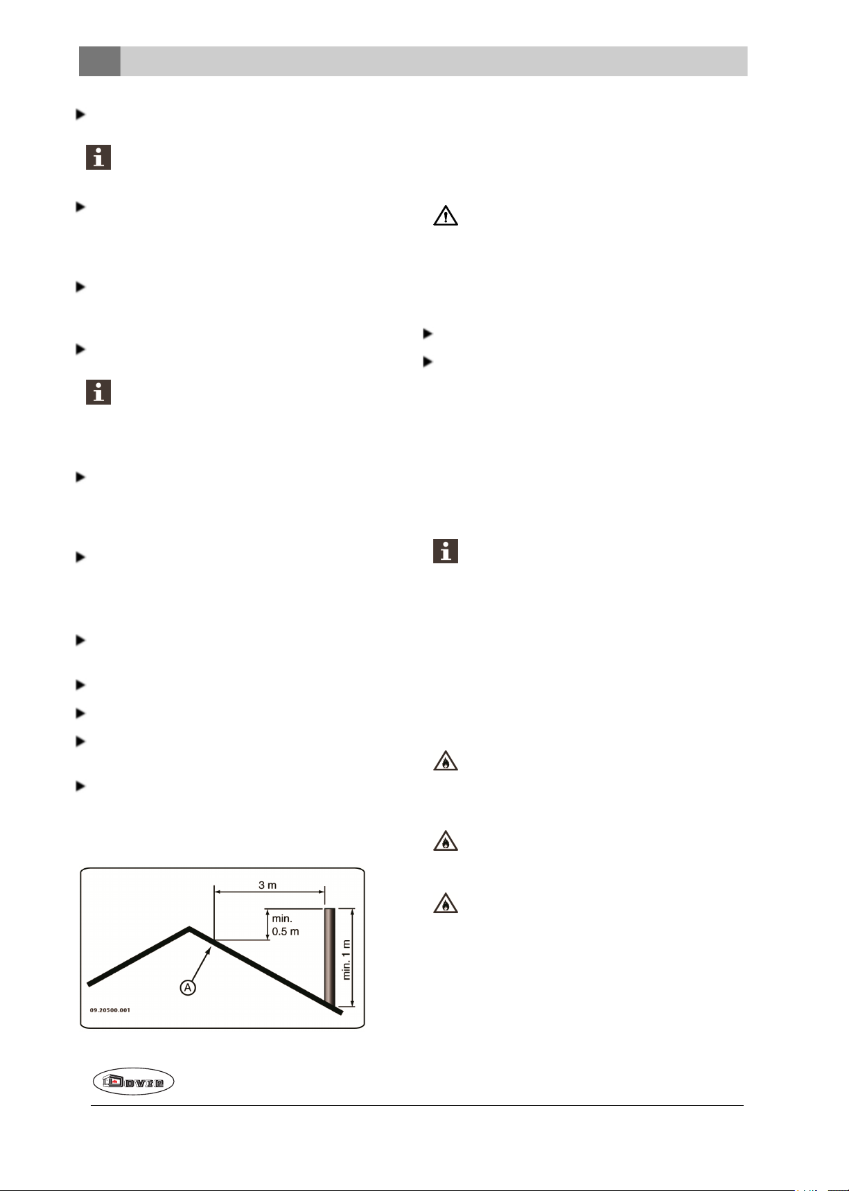
The flue should be at least 4metres high.
As a rule of thumb: 60cm above the ridge of the
roof.
If the ridge of the roof is more than 3metres from
the flue: use the measurements given in the following figure. A = the highest point of the roof
within a distance of 3metres.
As a rule of thumb, the air supply should be
5.5cm²/kW. Extra ventilation is needed when:
The appliance is in a well-insulated area.
There is mechanical ventilation, for example a central extraction system or an extraction hood in an
open kitchen.
You can provide extra ventilation by having a ventilation louvre fitted on the outside wall.
Make sure that other air consuming appliances (such
as tumble-driers, other heating appliances or a bathroom fan) have their own supply of outside air, orare
switched off when you use the appliance.
You can also connect the appliance to an outside air supply. A connection kit is supplied for
this purpose. This makes additional ventilation
unnecessary.
Floor and walls
The floor on which the appliance is placed must have
sufficient bearing capacity. Theweight of the appliance is given in the appendix “Technical Data
appendix”.
Protect flammableflooring from heat radiation
by means of a fireproof protective plate. See
the appendix "Distance from combustible
material".
Remove combustible material such as linoleum, carpets/rugs and similar materials below
the fireproof protective plate.
Keep sufficient distance between the appliance and combustible materials such as
wooden walls and furniture.
6
Subjectto change because of technicalimprovements.
Page 8
The connecting tubealso radiates heat. Ensure
09-20021-092
1
2
3
4
09-20021-090
1
2
3
that there is sufficient distance or a shield
between the connecting tube andcombustible
material.
The rule of thumb for a single-walledtubeis a
distance of 3x the diameter. If a lining shell is
fitted around the tube, a distance of 1x the diameter is permissible.
Carpets and rugs must be at least 80cm away
from the fire.
Use a fireproof floorplate to protect a flammable floor from any ash which may fall in front
of the stove. Thefloorplate must comply with
national standards.
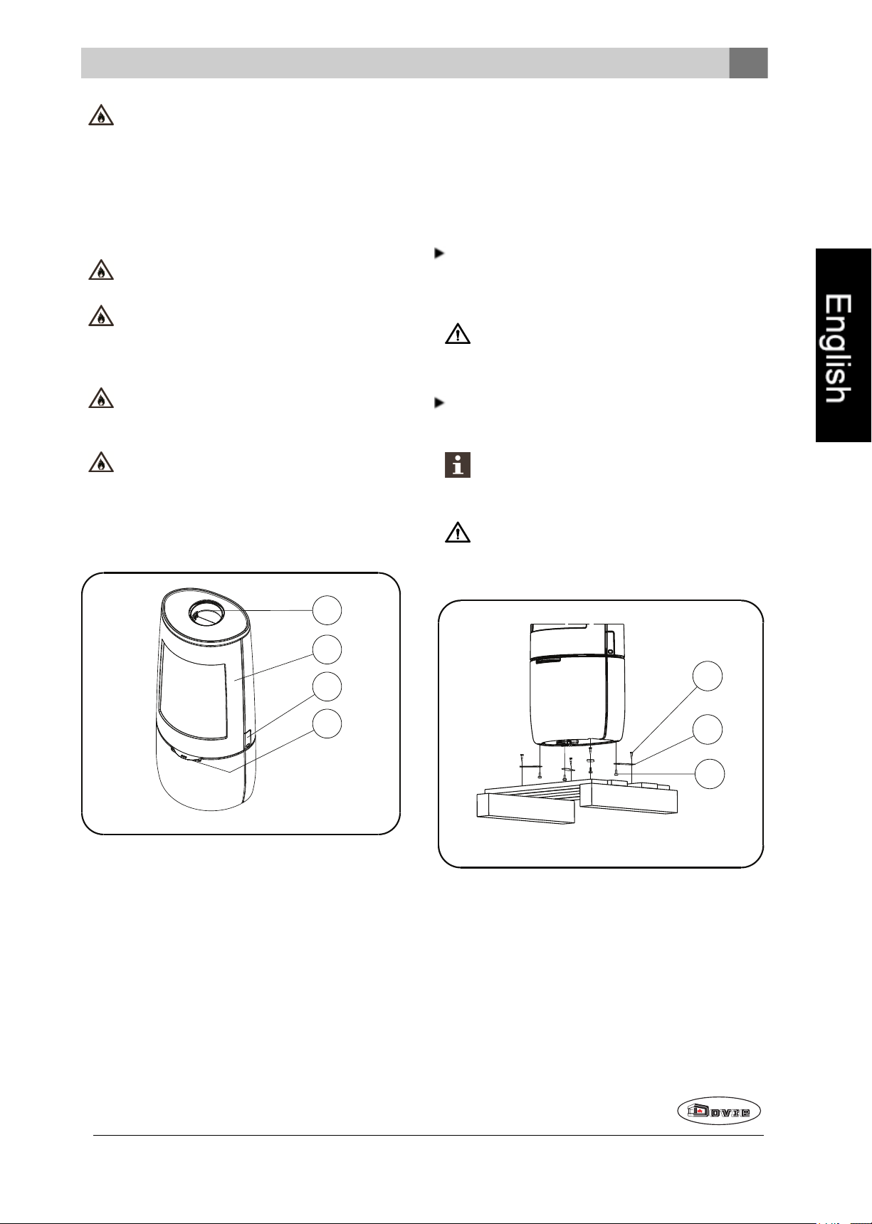
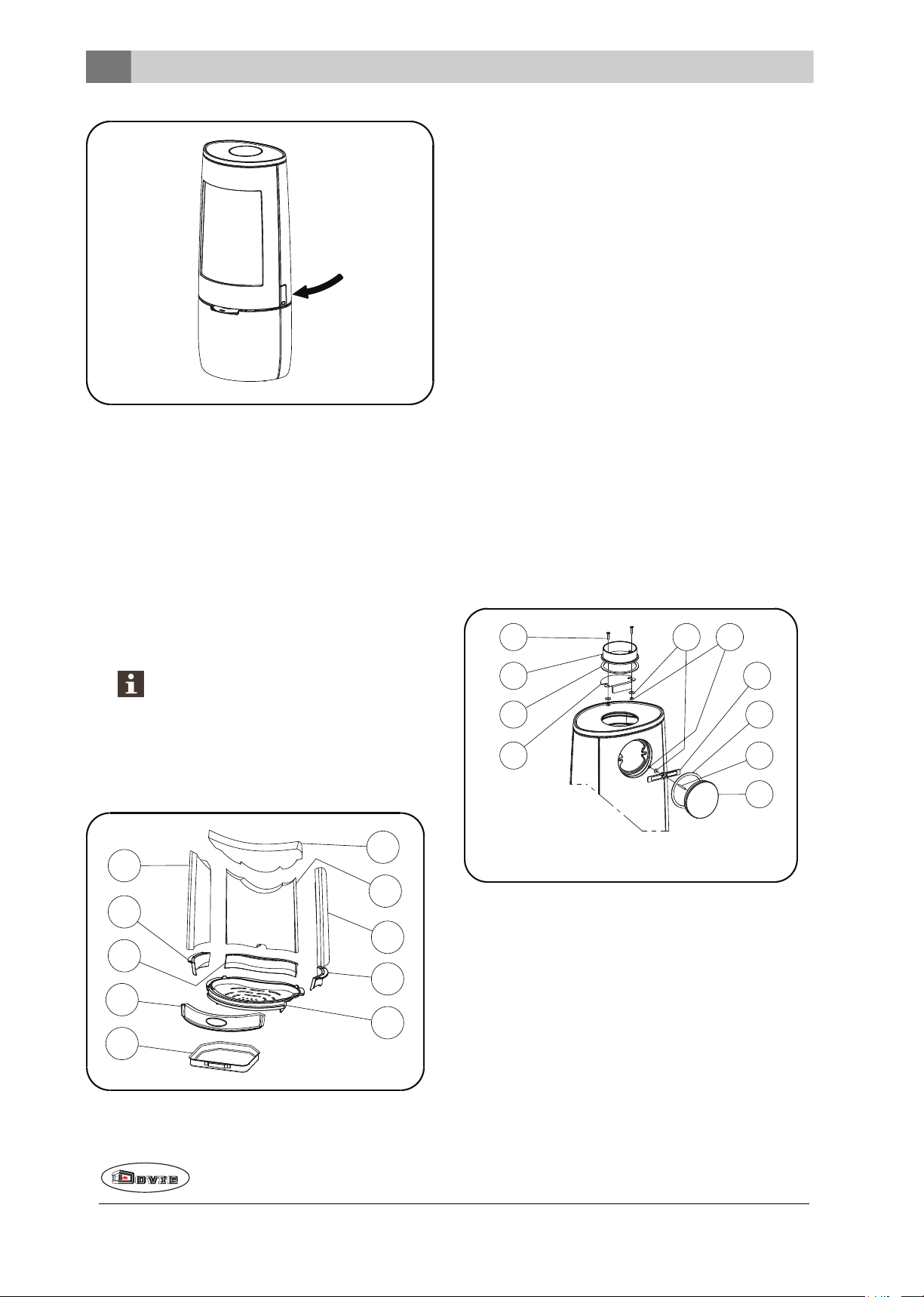
a glove has been supplied which you can use to protect your hand.
Installation
General preparation
Please check the appliance immediately after delivery for damage duringtransport or any other damageor defects. Theappliance is attached to the
pallet with screws at the bottom.
If you detect transport damageor any other
damage ordefects, do not use the appliance
andnotify the supplier.
For the dimensions of the fireproof protective
plate: see the appendix "Distance from combustible material".
For further requirements with respect to fire
safety, see the appendix "Distance from combustible material".
Product description
Remove removableparts (fire-resistant inner
plates, fire grate, top plate, ashtray) from the appliance before startinginstallation.
It is easier to move the appliance and to avoid
damage if the removable parts have been
removed.
Note the location of the removable parts, so
that you can re-position the parts in the correct
place later on.
1. Connection collar
2. Door
3. Latch
4. Air slide
Door lock
The appliance is supplied with the latch button (4)
installed. Thedoor is opened by pressing in the latch
button. As the latch button becomes warm during use,
Subjectto change because of technicalimprovements.
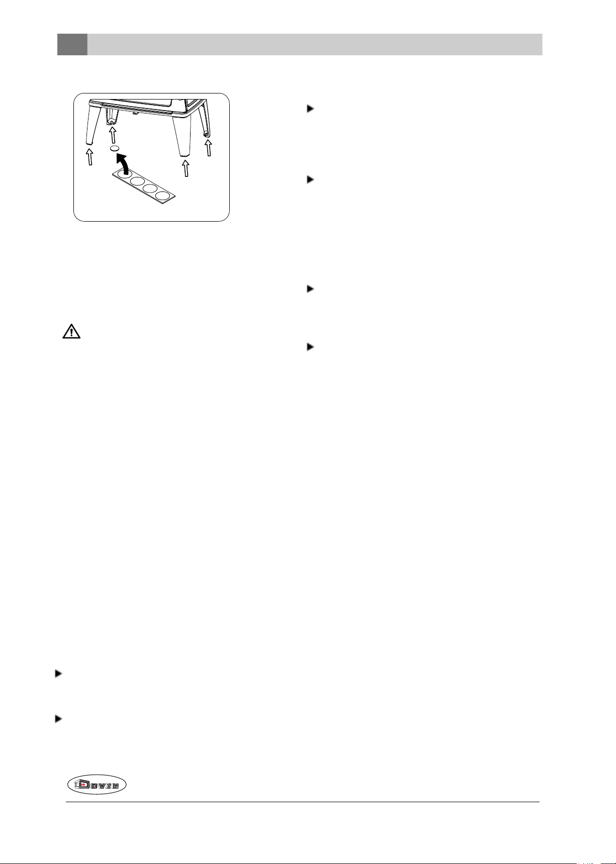
1. Remove the stove from the pallet by removing the
bolts (1).
2. Remove the mounting brackets (2) by turning the
adjustable feet (3) out.
3. Reassemble the adjustable feet (3).
4. Openthe door; see the following figure:
7
Page 9
09-20021-093
09-20021-099
01
02
03
04
05
06
07
08
09
10
Removable internal parts
09-20021-100
1
2
3
4
5 6
9
4
8
7
01 fire compartment base
02 fire basket rear
03 fire basket right
04 fire basket left
05 baffle plate
06 rear inner plate
07 inner plate right
08 inner plate left
09 fire basket front
10 ash pan
Preparing the connection to the flue
5. Remove the fire-resistant inner plates; see the following figure:
a. First remove the baffle plate(05).
b. Remove the inner plates right (07) and left (08).
c. Remove the rear inner plate (06).
d. Remove the fire basket at the front (09).
e. Remove the fire basket left (04) and right (03).
f. Remove the fire basket at the back (02).
g. Remove the grate (01)and the ash pan (10).
Vermiculite inner plates are light and tend
to be ochrous in colour on delivery. They
insulate the combustion chamber to boost
combustion.
When connecting the appliance to the flue, you can
choose to connect to the top orto the rear of the appli-
ance
Connecting to the top
As standard, the appliance is delivered with the connection collar fitted for a connection at the top, see following figure.
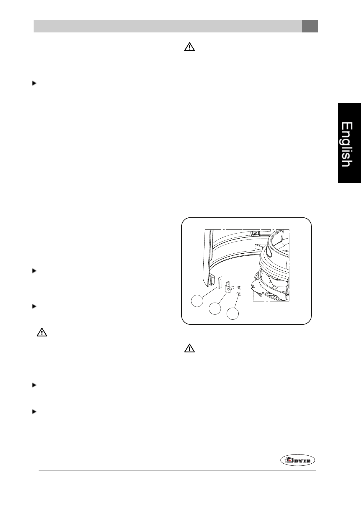
Connecting to the back
For a connection to the rear, the position of the connection collar needs to be changed. The connection
collar is attached with 2 M8 nuts (key 13). Proceed as
follows:
8
Disassembly (see previous drawing)
1. First remove the baffle plate.
Subjectto change because of technicalimprovements.
Page 10
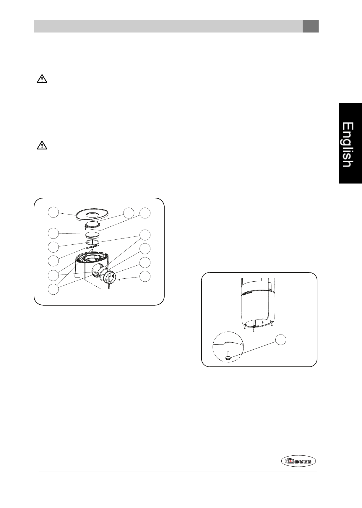
2. Remove the cover (7) from the back wall by remov-
09-20021-101
4
3
2
1
7
8
9
6
5
A
B
C
09-20021-091
1
ing the nut (6) and the clamping bracket (9).
3. Remove the cover (7) and the seal (8).
Check that the sealing tape onthe contact surface is not damaged. Replace the sealing tape
if it is damaged.
4. Disassemble the connecting collar(2) by undoing
the bolts (1).
5. Remove the connection collar (2), the seal (3) and
the materials supplied (1, 5, 6).
Preparing the outside air connection
If the appliance is installed in a room with insufficient
ventilation, you can install the outside air connecting
kit to the appliance.
The air supply tube is 100mm in diameter. If the tube
is smooth, it may be no longer than 12metres. If
accessories such as bends are used, the maximum
length (12m) must be reducedby 1m for each accessory used.
Check that the sealing tape onthe contact surface is not damaged. Replace the sealing tape
if it is damaged.
6. Remove the brake plate (4).
Assembly (see drawing below)
1. Remove the top plate (A).
Outside air connection via the wall
1. Make an opening in the wall (see the appendix,
"Measurements", for the correct position of the
opening).
2. Close the airconnection hermetically to the wall.
Installing and connecting
1. Position the appliance in the correct place, and
make sure it is level. The appliance is designed
with adjustable feet, which may already be mounted on the appliance or be included. Use these
adjustable feet so that the appliance can be placed
perfectly level.
2. Assemble the decorative cover (B) using the
materials supplied (C).
3. Fit the connecting collar (2), the seal (3)and the
brake plate (4) with the materials supplied (1, 5, 6)
on the back wall
4. Assemble the connection collar (7) and the seal (4)
with the materials supplied (8, 9, 5, 6).
5. Place the top plate (A) with assembleddecorative
cover (B) on the appliance and note the positioning
ridges.
Subjectto change because of technicalimprovements.
2. If the appliance is to be placed on a smooth floor,
the four anti-slip pads can be placed beneath the
adjustable feet to prevent the appliance from moving, see next image.
9
Page 11
09-20500-015
3. Connect the appliance to the flue hermetically.
4. For outside airsupply connection: connect the outside air supply to the connection kit which is fitted
to the appliance.
5. Re-position all removed parts to the correct places
in the appliance.
Never use the appliance without the fire-resistant inner plates.
The appliance is now ready for use.
Use
First use
When you use the appliance for the first time, make
an intense fire and keep it going for a good few hours.
This will cure the heat-resistant paint finish. This may
result in some smoke and odours. You could open windows and doors for a while in the area in which the
appliance is located.
Fuel
This appliance is only suitable for burning natural
wood; sawn and chopped wood that is sufficiently dry.
Do not use other fuels, as they can cause serious
damage to the appliance.
The following fuels may not be used as they pollute
the environment, and because they heavily pollute the
appliance and flue, which may lead to a chimney fire:
Treated wood, such as scrap wood, painted wood,
impregnated wood, preserved wood, plywood and
chipboard.
Wood
Hardwood, such as oak, beech, birch and fruit tree
wood is the ideal fuel for your stove. This type of
wood burns slowly with calm flames. Softwood
contains more resins, burns faster and sparks
more.
Use seasoned wood that contains no morethan
20% moisture. The wood should have been
seasoned for at least 2 years. Wood with a moisture content of 20% provides 4.2 kWh per kg wood.
Wood with a moisture content of 15% provides 4.4
kWh per kg wood. Freshly felled wood has a moisture content of 60% and only provides 1.6 kWh per
kg wood.
Saw the wood to size andsplit it while it is still
fresh. Fresh wood is easier to split, andsplit wood
dries more easily. Store the woodunder a roof
where the wind has free access.
Do not use damp wood. Damp logs do not produce
heat as all the energy is used in the evaporation of
moisture. This will result in a lot of smoke and soot
deposits on the appliance door and in the flue. The
water vapour will condense in the appliance and
can leak away through chinks in the stove, causing
black stains on the floor. It may also condense in
the chimney and form creosote. Creosote is a
highly flammable compound and may cause a chimney fire.
Lighting
You can check whether the flue has sufficient draught
by lighting a ball of paperabove the baffle plate. A cold
flue often has insufficient draught and consequently,
some smoke may escape into the room instead of up
the chimney. You can avoid this problem by lighting
the fire as described below.
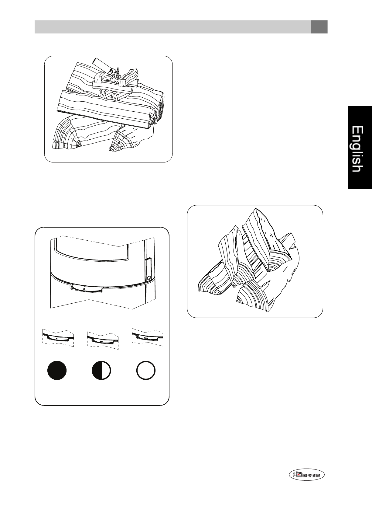
1. Stack two layers of medium sized logs crosswise.
2. Stack two to threelayers of kindling crosswise on
top of the logs.
3. Place a firelighterbetween the bottom layer of kindling and light the firelighter according to the instructions on the packaging.
Plastics, scrap paperand domestic waste.
10
Subjectto change because of technicalimprovements.
Page 12
09-20500-016
4. Close the appliance door and open the primary
09-20021-096
A
B
C
09-20500-017
andsecondary air inlets; see the following figure.
B:
o o Secondary air open (glass wash)
o Air for post-combustion open
A:
o Air for post-combustion open
(never close entirely for proper combustion)
Burning wood
After you have followed the instructions for lighting:
1. Slowly open the door of the appliance.
2. Spread the charcoal evenly across the bottom of
the stove base.
3. Stack a few logs on the charcoal.
5. Allow the fire develop into a good blaze until there
is a glowing bedof charcoal. You can then add fuel
andadjust the appliance, see the chapter "Stoking
with wood".
Open stacking
If the logs are stacked openly, the wood will burn
quickly as the oxygen can reach each log easily. If
you want to use the stove for a short while, make an
open stack.
C:
o o o Primary air open (when lighting the stove)
o o Secondary air open (glass wash)
o Air for post-combustion open
Subjectto change because of technicalimprovements.
11
Page 13
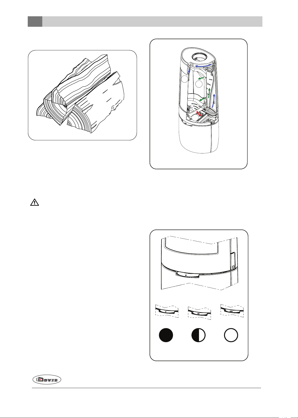
Compact stacking
09-20500-018
09-20021-095
1
2
3
09-20021-096
A
B
C
If the logs are stacked tightly, the wood will burnmore
slowly as the oxygen can only reach some logs easily. If you want to burn wood for a longer period, make
a compact stack.
4. Close the door of the appliance.
5. Close the primary air inlet and leave the secondary
air inlet open.
Fill the appliance to a maximum of a third.
Maximum amount of wood
To stoke continuously at the rated power, wood must
be addedevery 45 minutes. If you use a smaller
amount of wood each time, you can add wood more
often. Each stove is designed to work with a specific
maximum amount of wood. If you use a largerquantity
of wood, the heat output increases: As a result, the
hearth can become overloaded and parts can be damaged.
Permitted maximum quantity of fuel for wood with a
moisture percentage of 15%:
BOLD 7 KW has maximum filling of 1.5 kg wood per
45 minutes. Do not fill the combustion chamber more
that one third full, and neverstack woodabove the
openings for secondary air.
Controlling combustion air
The appliance has one air slide that regulates both the
primary air and the secondary air inlet. If the air slide is
in position 3, the primary andthe secondary air inlet is
open. As the air slide is further closed, the primary air
inlet andthenthe secondary airinlet is closed. If the
air slide is completely closed in position 1, a small air
vent remains open to allow for post-combustion under
the baffle plate.
The appliance has various features for air control; see
next figure.
12
Subjectto change because of technicalimprovements.
Page 14
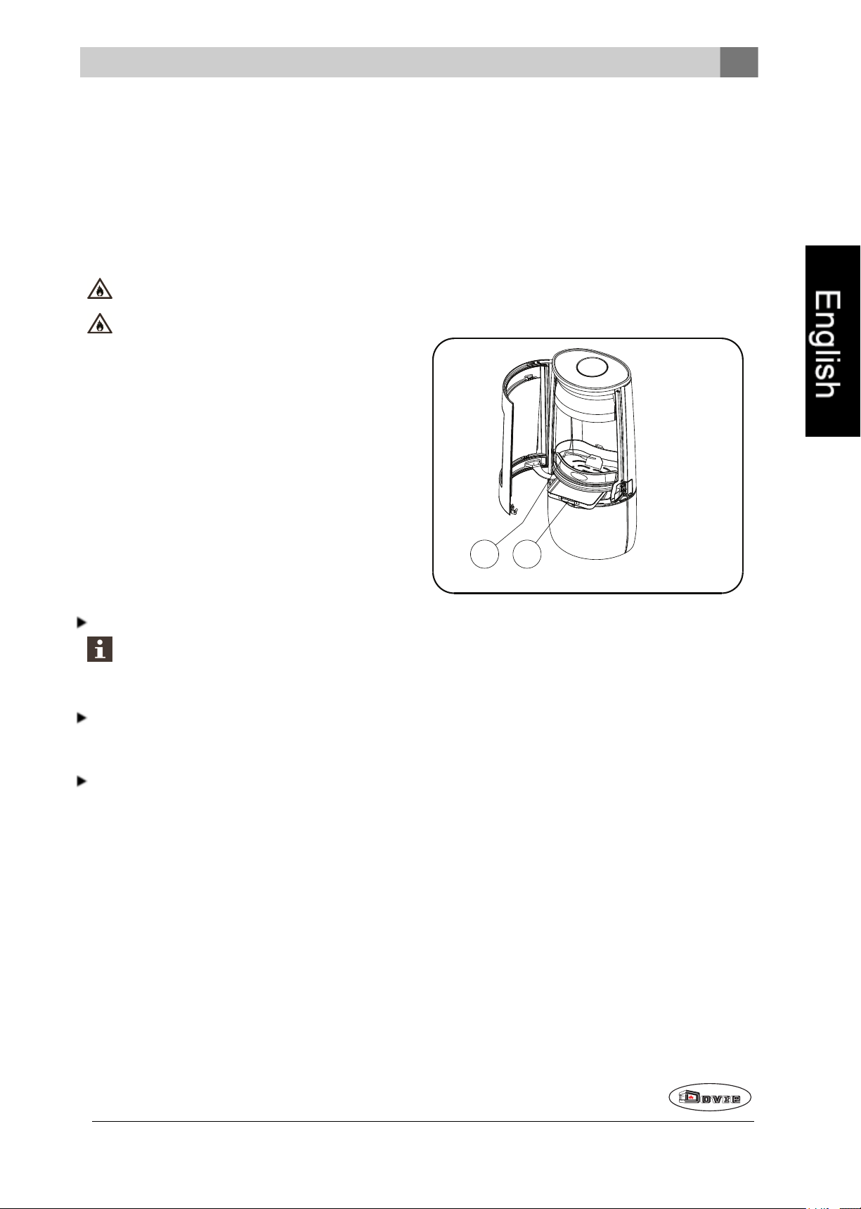
The primary airinlet regulates the air under the grate
09-20021-097
21
(1).
Removing ash
The secondary airinlet regulates the air for the glass
(airwash) (2).
The back wall has permanent vents (3) below the
baffle plate that allow for post-combustion.
Advice
Never burn wood with an open door.
Regularly burnwoodwith intense roaring fires.
If you burn at a low setting frequently, tar and
creosote may be deposited in the flue. Tar and
creosote are highly combustible substances.
Thicker layers of these substances may catch
fire if the temperature in the flue increases suddenly. By allowing the fire to burn very
intensely regularly, layers of tar and creosote
will disappear.
Low intensity fires can also cause tar deposits
on the stove window anddoor.
When the outside temperature is mild, it is better to burn wood intensely for a few hours
instead of having a low intensity fire for a long
period of time.
Control the airsupply using the air vent.
The air inlet not only supplies airto the fire but
to the glass as well, so that it does not quickly
become dirty.
Open the primary air inlet for the time being if the air
supply by the secondary air inlet is inadequate or if
you want to fan the fire.
After wood has been burnt, a relatively small amount
of ash remains. This ash bed is a good insulating layer
for the stove base plate and improves combustion. It
is a good idea to leave a thin layer of ash onthe stove
base plate.
The flow of air through the fire plate must not be
obstructed, however, and no ash may be allowed to
accumulate behind a cast-iron inner plate. Remove
the excess ash regularly.
1. Openthe door of the appliance.
2. Use the scraper supplied to sweep the excess ash
into the ash pan.
3. Using the glove supplied, remove the ash pan and
empty it.
4. Replace the ash pan and close the door of the
appliance.
Topping upwith a few logs regularly is better than
adding many logs in one go.
Extinguishing the fire
Do not add fuel and just let the fire go out. If a fire is
damped down by reducing the air supply, harmful substances will be released. Forthis reason, the fire
should be allowedto go out naturally. Keep an eye on
the fire until it has goneout. All air inlets can be closed
once the fire has died completely.
Subjectto change because of technicalimprovements.
Fog and mist
Fog and mist hinderthe flow of flue gases through the
flue. Smoke can blow back and cause a stench. If it is
not strictly necessary, it is better not to use the stove
in foggy and misty weather.
Resolving problems
Refer to the appendix "Diagnostic diagram" to resolve
any problems in using the appliance.
13
Page 15
Maintenance
Follow the maintenance instructions in this chapter to
keep the appliance in goodcondition.
Flue
In many countries, you are required by law to have
your chimney checked and maintained.
At the start of the heatingseason: have the chimney swept by a recognised chimney sweep.
Duringthe heating season and after the chimney
has not been used for a long time: have the chimney checked for soot.
At the end of the heating season: close off the chimney and plug with newspaper.
Cleaning and other regularly maintenance
Do not clean the appliance whenit is still
warm.
Clean the exterior of the appliance with a dry lintfree cloth.
You can cleanthe appliance interiorthoroughly at the
endof the heating season:
If necessary, first remove the fire-resistant inner
plates. See the chapter "Installation" for instructions on removing and installing the inner plates.
If necessary, clean the air supply ducts.
Remove the baffle plate at the top of the appliance
andcleanit.
Checking fire-resistant inner plates
Cast-iron inner plates last a long time if you
remove frequently the ash that can accumulate
behind them. If accumulated ash behind the
cast-iron plate is not removed, the plate will no
longer beable to dissipate the heat to the surroundings and this may cause the plate to warp
or crack.
Never use the appliance without the fire-resistant inner plates.
Cleaning the glass
Dirt clings less easily to well-cleaned glass. Proceed
as follows:
1. Remove dust and loose soot with a dry cloth.
2. Clean the glass with stove glass cleaner:
a. Apply stove glass cleaner to a kitchen sponge,
rubdown the entireglass surface and give the
cleaning agent time to react.
b. Remove the dirt with a moist cloth or kitchen
tissue.
3. Clean the glass again with a normal glass cleaning
product.
4. Rub the glass cleanwith a dry cloth or kitchen tissue.
Do not use abrasive or aggressive products to
clean the glass.
Wear household gloves to protect your hands.
If the glass in the appliance is broken or
cracked, it must be replacedbefore you can
use appliance again.
Ensurethat no stove glass cleaner runs
between the glass and the cast-iron door.
The fire-resistant inner plates areconsumables that
aresubject to wear andtear. Vermiculite inner plates
arefragile. Do not knock the inner plates with logs.
Check the fire-resistant inner plates frequently and
replace them when necessary.
See the chapter "Installation" for instructions on
removing and installing the inner plates.
The insulating vermiculite orchamotte inner
plates may develop hairline cracks, but this
does not affect their performance adversely.
14
Enamelled stove maintenance
Never clean the appliance while it is still hot. The
most effective way to clean the enamelled surface of
the stove is with a mild green soap and lukewarm
water. Use as little water as possible, rub the surface
dry and prevent the formation of rust. Wire wool or
other abrasives should never be used. Never place a
kettle directly onto an enamelled stove; use a stand to
prevent damage. Attention: Do not allow aggressive
acidic products to get onto enamelled components.
Subjectto change because of technicalimprovements.
Page 16
Lubrication
09-20021-094
2
3
1
Although cast-iron is slightly self-lubricating, you will
still need to lubricate moving parts frequently.
Lubricate the movingparts (such as guide systems,hingepins, latches and air slides) with heat
resistant grease that is available in the specialist
trade.
Touching up damaged paint
Small areas of damaged paint finish can be touchedup with a spray can of special heat-resistant paint,
available from your supplier.
Touching up the enamelled surface
Enamelling is a process carried out by traditional methods, meaning that it is possible that small colour differences and damage may occur. Theappliances
undergo a visual inspection in the factory, that is to
say, the inspector looks at the surface for a period of
10 seconds from a distance of 1 metre.
Any damage that does not stand out is regarded as
OK. A special heat-resistant paint is supplied with the
appliance to touch up any minor damagecaused during transport.
Apply the heat-resistant paint in thin layers and leave
to dry well before using the appliance.
Allow the sealant to harden fully before lighting
the appliance, as any moisture in the sealant
will form bubbles, resulting in a new air leak.
Adjust door closing
Check if the door closes properly. If required, the closing of the door can be set looseror tighter by adjusting
the distance between the locking cam and the door.
Proceed as follows:
1. Openthe door. The locking cam (2) is now freely
accessible; see next figure.
2. Unscrew the two screws (1) with which the locking cam is attached.
3. By removing the packing plate (3)behind the locking cam (2), the doorcloses more tightly. If the
door closes too tightly then insert an additional
packing plate behind the locking cam.
4. Tighten the two screws and check the closing of
the door once again.
Some enamel colours are temperature-sensitive. It
can happenthat the colour changes during use.
The original colour will return after the appliance
has cooled down.
If enamelled surfaces becomevery hot, hairline
cracks can occur. This is a normal phenomenon
andhas no impact on the functioning of the stove.
Ensurethat the stove is not overburdened. If it
does become overburdened thenthe surface
gets very hot possibly resulting in lasting damageto the enamel.
Checking the seal
Check whether the door sealing rope is still in good
condition and works well. The sealing rope is subject to wear and will need to be replaced over time.
Check the appliance for air leaks. Close any
chinks with stove sealant.
Replacing the glass
If the glass in the appliance is broken or
cracked, it must be replacedbefore the stove
is used again.
Proceed as follows:
1. Unscrew the four glass fixings with parts (3) and
(4)and remove the glass (2), see followingfigure.
2. Check the glass seal and, if necessary, fit a new
sealingrope.
3. Place the new glass in the grove andtighten the
glass fixings.
Subjectto change because of technicalimprovements.
15
Page 17

09-20021-098
1
2
3
4
BOLD spare parts
09-20021-099
01
02
03
04
05
06
07
08
09
10
13 70.79870.000 service kit cord
6 mm
14 70.79869.000 service kit cord
8 mm
15 70.79868.000 service kit self-
adhesive tape
16 70.72629.000 service kit spring
self-closing door
17 70.64315.000 service kit lock 1
1
1
1
1
BOLD 300/400
Pos. Part number Description Quantity
01 70.66559.021 fire compartment
base
02 70.77467.021 fire basket rear 1
03 70.77466.021 fire basket right 1
04 70.77465.021 fire basket left 1
05 70.76191.000 baffle plate 1
06 70.77564.000 rear inner plate 1
07 70.77563.000 side inner plate right 1
08 70.77562.000 side inner plate left 1
09 70.77458.021 fire basket 1
10 70.05216.000 ash pan 1
11 70.26384.000 curved glass 1
12 70.26101.041 service kit glass
fixing
16
1
1
Subjectto change because of technicalimprovements.
Page 18

Appendix 1: Technical data
Model BOLD 300/400
Nominal output 7 kW
Flue connection (diameter) 150mm
Weight 130 kg - 145 kg
Recommended fuel Wood
Fuel property, max. length 35 cm
Mass flow of flue gasses 5.6 g/s
Flue gas temperature measuredin the measurement section 246 °C
Temperature measured at appliance exit 356°C
Minimum draught 12 Pa
CO emission (13%O2)
NOx emission (13% O2)
CnHm emission (13%O2)
Particulate emission 22 mg/Nm³
Particulate emission in accordance with NS3058-NS3059 2.64 g/kg
Efficiency 80 %
0.10 %
90 mg/Nm³
102mg/Nm³
Subjectto change because of technicalimprovements.
17
Page 19

Appendix 2: Dimensions
09-20021-103
1 0 1 0
2 6 0
1 5 0
8 5 0
2 4 0
1 5 0
4 2 0
1 5 0
4 9 0
1 6 5
BOLD 300
18
Subjectto change because of technicalimprovements.
Page 20

BOLD 400
09-20021-102
1 1 3 0
3 8 0
3 7 5
9 8 5
4 1 5
1 0 0
1 5 0
4 9 0
1 9 0
1 5 0
Subjectto change because of technicalimprovements.
19
Page 21

Appendix 3: Distance from combustible material
09-20021-104
1
2
3 0 0
2 0 0 *
5 0
9 0 0
5 0
9 0 0
3 0 0
2 0 0 *
2 5 0
8 0 0
6 5 0
5 0
5 0
8 0 0
6 5 0
5 0
5 0
1 5 0
1 5 0
7 5 0
7 5 0
5 0
5 0
7 5 0
7 5 0
5 0
5 0
BOLD 300/400 - Minimum distances in millimetres for version without heat
shield
* with insulated stovepipe
1 Combustible material
2 Incombustible material, thickness 100 mm
Please note: In order to guarantee the supply of combustion air when there is no outside air supply connection, the distance from the connection collar for the outside air to the wall must be at least 20 mm. If
necessary, the connection collar can be removed.
20
Subjectto change because of technicalimprovements.
Page 22

BOLD 300/400 - Minimum distances in millimetres for version with heat
09-20021-106
1
2
5 0
5 0
9 0 0 90 0
5 0
2 5 0
5 0
5 0
5 0
8 0 0
6 5 0
5 0
5 0
8 0 0
6 5 0
1 0 0
1 0 0
5 0
5 0
7 5 0
7 5 0 7 5 0
7 5 0
5 0
5 0
shield and insulated stovepipe
1 Combustible material
2 Incombustible material, thickness 100 mm
Please note: In order to guarantee the supply of combustion air when there is no outside air supply connection, the distance from the connection collar for the outside air to the wall must be at least 20 mm. If
necessary, the connection collar can be removed.
Subjectto change because of technicalimprovements.
21
Page 23

BOLD - Dimensions of fireproof floor plate
09-20021-105
A
B
B
Minimum dimensions of fireproof floor plate
A (mm) B (mm)
Din 18891 500 300
Germany 500 300
Finland 400 100
Norway 300 5
22
Subjectto change because of technicalimprovements.
Page 24

Appendix 4: Diagnosis diagram
Problem
Wood will not stay lit
Gives off insufficient heat
Smoke emissions into the room when adding wood
Fire in appliance is too intense, is hard to adjust
Deposit on the glass
possible cause possible solution
Insufficient draught
Wood too damp Use wood withno more than 20%moisture.
Logs too large
Wood stacked incorrectly
Flue does not work properly
Chimney stack incorrect Sufficientlyhigh above the roof, no obstacles in the vicinity
Air inlets set incorrectly Open the air inlets completely.
Appliance connected to the flue incorrectly
Vacuum in area in whichthe applianceis
installed
Insufficient supplyof fresh air
Bad weather
? Inversion (reversed air flow inchimney
because of a highoutside temperature),
extreme wind speeds
A cold flue usuallyfailsto create sufficient draught. Follow the instructionsfor starting a fire in the ‘Use’ section; open a window.
Use small pieces ofkindling.Use split logs no larger than 30 cm incircumference.
Stackthe logsin away that allows adequate air flow between the
logs(open stacking, see "Burning wood")
Check whether the chimney meets the requirements: at least 4
metres high, correct diameter, well-insulated, smooth inside, not too
many bends, no obstructions in chimney(bird's nest, too much soot
deposit), hermetically tight (no chinks).
Connection should be hermeticallytight.
Switch off extraction systems.
Provide an adequate air supply; ifnecessary use outside air connection.
We recommend youdon't use the appliance in the case of inversion.
If required, install an extra hood on the flue to increase the draught.
Draught in the livingroom
Flames touchthe glass
Appliance isleakingair Check the door seals and appliancejoints.
Subjectto change because of technicalimprovements.
Avoiddraught in the livingroom, do not place the appliance near a
door or heating air ducts.
Make sure the wood isnot positioned too close to the glass. Slide the
primary air inlet cover closer to the "Closed" position.
23
Page 25

Index
A
Adding wood
smoking appliance 23
Adverse weather conditions, do not burn wood 13
Aerating the fire 13
Air combustion control 12
Air control 12
Air inlets 11
Air leak 15
ash 13
Ash pan
open 13
Ashes
remove 13
Controlling air supply 13
Creosote 13
D
Damage 7
Damp wood 10
Dimensions 18
Door
adjust 15
closing 15
Locking cam
packing plate 15
opening 7
sealingrope 15
Draught 17
Drying wood 10
B
Bearing capacity of floor 6
Burning 11
adding fuel 11
appliance is hardto adjust 23
fire is too intense 23
insufficient heat 23
topping up fuel 13
Burning wood
insufficient heat 13
C
Cap on the flue 6
Carpet 6
Cast iron inner plates 8
Chinks in appliance 15
Cleaning
appliance 14
glass 14
Combustible material
distance from 20
Connecting
dimensions 18
Connecting outside air supply 9
Connection collar for connection to chimney 8
Connection to chimney
at the rear 8
at the top 8
rear 8
top 8
E
Efficiency 4, 17
Email
maintenance 14
External air supply
connecting to 10
Extinguishingthe fire 13
F
Fan 6
connecting outside air supply 9
ruleof thumb 6
Fan louvre 6
Filling level of the appliance 12
Finishing coat, maintenance 15
Fire
extinguishing 13
kindle
Lighting 10
Fire-resistant inner plates
maintenance 14
remove 8
Fire safety
distance from combustible material 20
floor 6
furniture 6
walls 6
Fireproof inner plates
warning 10
24
Subjectto change because of technicalimprovements.
Page 26

Floor
smooth 9
Floors
bearingcapacity 6
fire safety 6
Flue
connecting to 10
connection diameter 17
height 6
maintenance 14
requirements 5
Flue cap 6
Flue gas
temperature 4, 17
Flue gasses
mass flow 17
Fog, donot burn wood 13
Fuel
adding 12
necessary amount 13
suitable 10
topping up 13
unsuitable 10
wood 10
G
L
Lighting fire 10
Lubricant 15
Lubricate 15
M
Maintenance
Clean appliance 14
cleaning the glass 14
emai 14
Fire-resistant inner plates 14
flue 14
lubrication 15
sealing 15
Mist, do not burn wood 13
N
Nominal output 13, 17
O
Open
ash pan 13
Opening
door 7
Outside air supply 6, 9
Glass
cleaning 14
cracked 15
deposit 23
replacing 15
Glass damaged 15
H
Heat, insufficient 13, 23
Hinge
adjust 15
I
Inner plate
vermiculite 8
Inner plates, fire-resistant
remove 8
Installing
dimensions 18
K
Kindling 23
P
Paint
Smoke
during first use 10
Particulate emission 17
Parts, removable 7
Positioning
anti-slip 9
Preventing chimney fire 13
Primary air inlet 11
R
Removable parts 7
Remove
fire-resistant innerplates 8
Removing ash 13
Replacing
glass 15
Subjectto change because of technicalimprovements.
25
Page 27

S
Screens
deposit 23
Sealing rope for door 15
Secondary air inlet 11
Smoke emissions into the room 5
Smoking appliance 23
Smooth floor 9
Softwood 10
Solving problems 13, 23
Stacking logs 11
Storingwood 10
Stove glass cleaner 14
Suitable fuel 10
Sweeping flue 14
T
Tar 13
Temperature 17
Topping upwith fuel 13
drying 10
right sort 10
storing 10
will not stay lit 23
U
Unsuitable fuel 10
V
Vermiculite
fire-resistant 8
Vermiculite inner plates 8
W
Walls
fire safety 6
Warning
chimney fire 10, 13
chimney fires 5
fireproof inner plates 10
flammable materials 5
glass broken or cracked 5, 14-15
hot surface 5
placinga load on door 5
requirements 5
stove glass cleaner 14
terms and conditions for insurance 5
ventilation 5-6
Weight 17
Wood 10
damp 10
26
Subjectto change because of technicalimprovements.
Page 28

Page 29

Innhold
Innledning 2
Ytelseserklæring 3
Sikkerhet 5
Monteringsvilkår 5
Generelt 5
Skorstein 5
Ventilasjonav rommet 6
Gulv og vegger 6
Produktbeskrivelse 7
Montering 7
Generelle forberedelser 7
Forberede tilknytning til skorstein 8
Forberede direkte tilførsel av forbrenningsluft 9
Plasseringog tilkobling 9
Bruk 10
Første gangs bruk 10
Brensel 10
Opptenning 10
Fyring med ved 11
Maksimal vedmengde. 12
Reguleringav forbrenningsluft 12
Bålet slukker 13
Tømme aske 13
Tåke 13
Eventuelle problemer 13
Vedlikehold 13
Skorstein 13
Rengjøring og annet regelmessig vedlikehold 13
Utskiftingsdeler deler BOLD 16
Vedlegg 1: Tekniske data 17
Vedlegg 2: Mål 18
Vedlegg 3: Avstand til brennbart materiale 20
Vedlegg 4: Diagnoseskjema 23
Indeks 24
Det tas forbehold om endringer p.g.a. tekniske forbedringer.
1
Page 30

Innledning
Kjære bruker,
Ved å kjøpe dette ildstedet fra DOVRE har du valgt et
kvalitetsprodukt. Dette produktet inngåri en ny
generasjon med energieffektive og miljøvennlige
ildsteder. Disse ildstedene gjør optimal bruk av både
konveksjonsvarmen og strålingsvarmen.
Ditt DOVRE ildsted erprodusert ved hjelp av de
mest moderne produksjonsmetoder. Hvis det
skulle være noe i veien med ditt ildsted, kan du
alltid få hjelp av DOVRE service.
Ildstedet må ikke modifiseres; bruk kun originale
deler.
Ildstedet er beregnet på installasjon i en stue.
Ildstedet må tilkobles til en skorstein som fungerer
godt.
Vi anbefaler at ildstedet tilsluttes av en autorisert
installatør.
DOVRE kan ikke holdes ansvarlig for problemer
ellerskade som skyldes feil montering.
Ved monteringog bruk må man følge
sikkerhetsforskriftene som beskrives nedenfor.
I denne anvisningen leser du hvordan du monterer,
bruker og vedlikeholder ditt DOVRE ildsted. Hvis du
ønsker merinformasjoneller tekniske data eller hvis
det oppstår problemer under monteringen, bør du først
ta kontakt med leverandøren.
© 2016 DOVRE NV
2
Det tas forbehold om endringer p.g.a. tekniske forbedringer.
Page 31

Ytelseserklæring
I samsvar med byggevareforordning 305/2011
Nr. 051-CPR-2015
1. Unik identifikasjonskode for varetypen:
BOLD 300 -400 / 7kW
2. 2. Type-, parti- eller serienummer, eller annen identifiseringsmåte for byggeproduktet, som
foreskrevet i paragraf 11, fjerde ledd:
Unikt serienummeret.
3. Tilsiktet bruk av byggeproduktet, i overensstemmelse med den gjeldende harmoniserte tekniske
spesifikasjonen, slik det er bestemt av produsenten:
Ildsted fyrt medfast brensel uten produksjon av varmtvanni henhold til EN 13240.
4. Navn, registrert handelsnavn eller registrert handelsmerke og kontaktadresse til produsenten, som
foreskrevet i paragraf 11, femte ledd:
Dovre N.V. Nijverheidsstraat 18 2381 Weelde Belgium.
5. Hvis aktuelt, navn og kontaktadresse til fullmaktshaver hvis mandat omfatter de oppgaver nevnt i
paragraf 12, andre ledd:
-
6. Systemet eller systemene for bedømmelse og verifisering av prestasjonsbestandigheten til
byggeproduktet, nevnt i vedlegg V:
System 3
7. Hvis ytelseserklæringen gjelder et byggeprodukt som faller under den harmoniserte normen:
Instansen KVBG, registrert under nummer 2013, har under engasjement utført en typegodkjenning under
system 3 og har levert testrapport nr. H2015/0078.
8. Hvis ytelseserklæringen gjelder et byggeprodukt som det er avgitt en europeisk teknisk
bedømmelse av:
-
Det tas forbehold om endringer p.g.a. tekniske forbedringer.
3
Page 32

9. Angitt prestasjon:
Den harmoniserte normen EN 13240:2001/A2 ;2004/AC :2007
Grunnleggende karakteristikker Prestasjoner Ved
Brannsikkerhet
Ildbestandighet A1
Minimal avstand i mm
Avstandtil brennbart materiale
Bakside: 300
Side: 250
Risiko for utfallende glødende deler Oppfyller kravet
Utslipp av forbrenningsprodukter
CO: 0,10 % (13 % O2)
Overflatetemperatur Oppfyller kravet
Elektrisk sikkerhet -
Lett å rengjøre Oppfyller kravet
Maksimalt arbeidstrykk -
Røykgasstemperaturved nominell effekt 246 °C
Mekanisk motstand (båret vekt av skorstein) Ikke bestemt
Nominell effekt 7kW
Utnyttelse 80 %
10. Prestasjonene til produktet som er beskrevet i punkt 1 og 2 oppfyller kravene til prestasjonene i
punkt 9.
Denne ytelseserklæringen gis under det eksklusive ansvaret til fabrikanten meldt i punkt 4:
01/10/2013 Weelde
Tom Gehem
CEO
På grunn av fortløpende produktutvikling forbeholdervi oss retten til å endre spesifikasjonene i denne brosjyren
uten forutgående kunngjøring.
DOVRE N.V.
Nijverheidsstraat 18 Tlf.: +32 (0) 14 65 91 91
B-2381 Weelde Faks: +32 (0) 14 6590 09
Belgia E-post : info@dovre.be
4
Det tas forbehold om endringer p.g.a. tekniske forbedringer.
Page 33

Sikkerhet
NB! Alle sikkerhetsregler må følges nøye.
at det kan komme giftige gasser inn i rommet.
Se kapitlet "Monteringsvilkår" for mer
informasjon om ventilasjon.
Les nøye anvisningene om montering, bruk og
vedlikehold som medleveres til ildstedet, før du
tar ildstedet i bruk.
Ildstedet må monteres i samsvar med reglene
som gjelder i ditt land.
Alle lokale forskrifter og bestemmelser i
nasjonale ogeuropeiske standarder må
overholdes ved montering av ildstedet.
Vi anbefaler at ildstedet monteres av en
autorisert installatør. Denne kjenner til de
gjeldende bestemmelsene og forskriftene.
Ildstedet er konstruert for oppvarming. Alle
overflater, også glasset og tilkoblingsrøret, kan
bli svært varme (over 100°C)! Bruk et
kaldhåndtak eller en varmebestandig hanske.
Sørg for tilstrekkelig avskjerming hvis små
barn, funksjonshemmede, eldre eller dyr
befinner seg i nærheten av ildstedet.
Sikkerhetsavstandene til brennbart materiale
må nøye overholdes.
Monteringsvilkår
Generelt
Ildstedet må tilkobles til en skorstein som fungerer
godt.
For tilkoblingsmålene: se vedlegget "Tekniske
data".
Forhør deg med brannvesenet og/eller
forsikringsselskapet om eventuelle spesifikke krav
og forskrifter.
Skorstein
Skorsteinen er nødvendig for:
Fjerning av røykgassene ved naturlig trekk.
Den varme luften i skorsteinen er lettere enn
uteluften ogvil derfor stige.
Inntak av luft som er nødvendig for forbrenningen
av brenselet i ildstedet.
Legg ikke gardiner, klær, klesvask eller annet
brennbart materiale på eller i nærheten av
ildstedet.
Bruk ikke lett antennelige eller eksplosive
stoffer i nærhetenav ildstedet mens det er i
bruk.
Forebygg pipebrann ved å få utført regelmessig
feiing av skorsteinen. Fyr aldri mens ildstedets
dør er åpen.
Ved pipebrann: steng ildstedets luftregulatorer
og tilkall brannvesenet.
Hvis ildstedets glass er knust eller sprukket,
må glasset skiftes før ildstedet brukes igjen.
Ikke bruk makt på døren, unngåat barn trekker
i den åpne døren, sitt ellerstå aldri på den åpne
døren, og plasser aldri tunge gjenstander på
den.
Sørg for at det er tilstrekkelig ventilasjon i
rommet hvor ildstedet står. Ved utilstrekkelig
ventilasjon blir forbrenningen ufullstendig, slik
En skorstein som ikke fungerergodt kan forårsake
røyk i rommet når døren åpnes. Skade pågrunn av
tilbakeslag av røyk dekkes ikke av garantien.
Ikke tilknytt flere ildsteder (f.eks.
sentralfyrkjele) på den samme skorsteinen,
med mindre lokale eller nasjonaleforskrifter
tillater det. Hvis to ildsteder skal tilknyttes må
det være en høydeforskjell på minimum 200
mm mellom dem.
Rådfør deg med din installatør vedrørende råd om
skorsteinen. Se den europeiske standarden EN13384
for riktig beregning av skorsteinen.
Skorsteinen må oppfylle følgende krav:
Skorsteinen må være laget av ildfast materiale,
helst keramikk eller rustfritt stål.
Skorsteinen må være lufttett, godt feid og ha
tilstrekkelig trekk.
15-20Pa trekk/undertrykk ved normal
belastning er ideelt.
Det tas forbehold om endringer p.g.a. tekniske forbedringer.
5
Page 34

Skorsteinen må være mest mulig vertikal, fra
ildstedets røykuttak. Bend og horisontale deler
forstyrrerutslippet av røykgasser og kan føre til
opphoping av sot.
Den innvendigediameteren må ikke være for stor,
for å unngå at røykgassene blir for mye avkjølt slik
at trekken avtar.
Skorsteinen bør helst ha sammediameter som
røykrørstussen.
For nominelle diameteren : se vedlegget
"Tekniske data". Hvis skorsteinen er godt
isolert, kan diametereneventuelt være større
(maksimalt det doble tverrsnittet av
røykrørstussen).
Tverrsnittet på skorsteinen må være konstant.
Videre deler og (særlig) innsnevringer forstyrrer
utslippet av røykgasser.
Ved bruk av pipehatt/røykhatt: Pass på at
pipehatten ikke innsnevrer skorsteinens utløp og at
pipehatten ikke hindrer røykgassene.
Skorsteinens munning må befinne seg i en sone
som ikke forstyrres av bygninger, trær eller andre
hindringer i nærheten.
Den delen av skorsteinen som befinner seg utenfor
huset må være isolert.
Ventilasjon av rommet
Ildstedet trenger luft (oksygen)for å oppnå god
forbrenning. Luften tilføres fra rommet hvor ildstedet
står gjennom luftregulatorer.
Ved utilstrekkelig ventilasjon blir forbrenningen
ufullstendig, slik at det kan komme giftige
gasser inn i rommet.
Tommelfingerregelen er at lufttilførselen skal være
5,5cm²/kW. Det kreves ekstra ventilasjon hvis:
Ildstedet står i et godt isolert rom.
I rom med mekanisk ventilasjon, f.eks. sentralt
avtrekkssystem eller avtrekksvifte i et åpent
kjøkken.
Det oppnås ekstra ventilasjonved å montere en
ventilasjonsrist i ytterveggen.
Sørg for at annet utstyr som bruker luft (f.eks.
tørketrommel, et annet ildsted eller baderomsvifte) har
egen tilknytningtil friskluft, eller er slått av når du fyrer
med ildstedet.
Ildstedet kan også tilkobles frisklufttilførsel. Et
tilkoblingssett for dette medfølgAer. Ved bruk
av et slikt sett er ekstra ventilasjon ikke
nødvendig.
Skorsteinen må ha en høyde på minst 4meter.
En tommelfingerregel: 60cm over takets høyeste
punkt.
Hvis takets høyeste punkt befinnerseg mer enn
3meter fra skorsteinen: følg målenesom vises i
neste figur. A = takets høyeste punkt innenfor en
avstand på 3meter.
Gulv og vegger
Gulvet som ildstedet monteres på må hatilstrekkelig
bæreevne. For ildstedets vekt: se vedlegget
"Tekniske data".
Beskytt et brennbart gulv med en brannsikker
gulvplate mot varmestråling. Se vedlegget
"Avstand til brennbart materiale".
Fjern brennbart materiale som linoleum, teppe
osv. underden brannsikre gulvplaten.
Sørg for tilstrekkelig avstand mellom ildstedet
og brennbart materiale som f.eks. treveggerog
møbler.
Tilkoblingsrøret utstråler også varme. Sørg for
tilstrekkelig avstand og avskjerming mellom
tilkoblingsrøret og brennbare materialer.
Tommelfingerregelen for et enkeltvegget rør er
en avstand på tre ganger diameteren. Hvis det
6
Det tas forbehold om endringer p.g.a. tekniske forbedringer.
Page 35

er enkledning rundt røret, er en avstand som
09-20021-092
1
2
3
4
09-20021-090
1
2
3
tilsvarer diameteren tillatt.
Montering
Et teppe må ligge minimal 80cm fra ilden.
Beskytt et brennbart gulv foran ildstedet med
en brannsikker gulvplate mot aske som kan
falle ut av ildstedet. Gulvplaten må oppfylle
dennasjonale standarden.
For målene til den ikke-brennbare gulvplaten:
se vedlegget: se vedlegget "Avstandtil
brennbarematerialer".
For andre krav i forbindelse med
brannsikkerhet: se vedlegget "Avstand til
brennbarematerialer".
Produktbeskrivelse
Generelle forberedelser
Kontroller ildstedet på (transport)skade og
eventuelle mangler umiddelbart etter at det er
levert. Ildstedet er montert på undersiden til pallen.
Hvis du konstaterer (transport)skade eller
mangler, må duikke ta ildstedet i bruk men
varsle leverandøren.
Fjern de demonterbare delene (indre brennplater,
bunnrist, topplate og askeskuff) fra ildstedet før du
monterer ildstedet.
Ved å fjerne de demonterbare delene, blir det
lettere å flytte ildstedet og unngå skader.
Pass på deres opprinnelige posisjon når du
fjerner demonterbare deler, slik at dekan
monteres på riktig sted senere.
1. Rørstusse
2. Dør
3. Lukkemekanisme
4. Luftventil
Dørlukker
Ildstedet leveres med montert dørhendel (4). Døren
åpnes ved å trykke dørhendelen inn. Dørhendelen kan
bli meget varm underbruk, og derfor følger det med en
hanske som kan brukes til beskyttelse av hånden.
Det tas forbehold om endringer p.g.a. tekniske forbedringer.
1. Ta ildstedet av pallen ved å fjerne boltene (1).
2. Fjern traversene(2) ved å skru ut
justeringsbeinene (3).
3. Monter justeringsbeinene (3) igjen.
4. Åpne døren; se neste figur.
7
Page 36

09-20021-093
5. Fjern de indrebrennplatene; se neste figur.
09-20021-099
01
02
03
04
05
06
07
08
09
10
09-20021-100
1
2
3
4
5 6
9
4
8
7
a. Fjern først hvelvplaten(05).
b. Fjern brennplatene til høyre (07) og venstre
(08).
c. Fjern brennplaten bak (06).
02 kubbestopper bak
03 kubbestopper høyre
04 kubbestopper venstre
05 hvelvplate
06 brennplaterbak
07 brennplate høyre
08 brennplate venstre
09 kubbestopper foran
10 askeskuff
Forberede tilknytning til skorstein
Ved tilkobling av ildstedet til en skorstein kan man
velge tilkoblingpå ildstedets topp ellerbakside .
Tilkobling til toppen
Ildstedet leveres standard med rørstussen montert for
tilkobling påtoppen, se neste figur.
d. Fjern kubbestopperen på forsiden (09).
e. Fjern kubbestopperene til venstre (04) og
høyre (03).
f. Fjern kubbestopperen på baksiden (02).
g. Fjern risten (01) ogaskeskuffen(10).
Ildfaste indre brennplater av vermikulitt har
lav vekt og ersom regel okerfarget ved
levering. De isolerer brennkammeret slik at
forbrenningen blir bedre.
Tilkobling på baksiden
For tilkobling til baksiden må rørstussens posisjon
endres. Rørstussen er festet med 2 M8-muttere(13
mm nøkkel). Gå fram slik:
Demontering (forrige tegning)
1. Fjern hvelvplaten.
2. Demonter blindlokket (7) fra bakveggen, ved å
løsne mutteren (6) og fjerne klembøylen (9).
Løse innvendige deler
01 brenselrist
3. Fjern blindlokket (7) og tettingen (8).
Kontroller om tetningsbåndet på kontaktflaten
8
Det tas forbehold om endringer p.g.a. tekniske forbedringer.
Page 37

er uten skader. Skift tetningsbåndet hvis det er
09-20021-101
4
3
2
1
7
8
9
6
5
A
B
C
09-20021-091
1
09-20500-015
skadet.
4. Demonter rørstussen (2) ved å løsne boltene (1).
5. Fjern rørstussen (2), tettingen (3) og
festematerialene(1, 5, 6).
Kontroller om tetningsbåndet på kontaktflaten
er uten skader. Skift tetningsbåndet hvis det er
skadet.
12 meter. Hvis det brukes deler som bend o.l. skal
det trekkes fra 1meter fra den maksimale lengden (12
meter) for hvert bend o.l.
Frisklufttilførsel gjennom veggen
1. Lag et tilkoblingshull i veggen (se vedlegget,
"Mål", for riktig posisjon for tilkoblingshull).
2. Lufttilførselsrøret skal tilkobles lufttett til veggen.
6. Fjern bremseplaten (4).
Montering (se etterfølgende tegning)
1. Fjern topplaten (A).
2. Monter det medsendte pyntelokket (B) med de
tilhørende festematerialene (C).
3. Monter røykrørstussen (2) og tetningen (3)og
bremseplaten (4) med festematerialene (1, 5, 6) til
bakveggen.
4. Monter blindlokket (7)og tettingen (4) med
festematerialene(8, 9, 5, 6).
Plassering og tilkobling
1. Sett ildstedet på riktig sted, jevnt og i vater.
Ildstedet harjusteringsbensom alleredeer
montert til ildstedet eller leveres løse. Bruk disse
justeringsbena slik at ildstedet kan justeres helt i
vater.
2. Hvis ildstedet står på et glatt underlag, kan du
plassere de fire antiskliputene under
justeringsbeinene for å unngå at ildstedet
forskyves, se neste bilde.
5. Plasser topplaten (A) med det monterte
pyntelokket (B) på ildstedet og pass på
posisjoneringstappene.
Forberede direkte tilførsel av forbrenningsluft
Hvis ildstedet monteres i et rom med utilstrekkelig
ventilasjon, kan dumonteretilkoblingssettet for
frisklufttilførsel på ildstedet.
Lufttilførselsrøret har en diameter på 100mm. Hvis
det brukes et glatt rør kan dette ha en lengdepå maks.
Det tas forbehold om endringer p.g.a. tekniske forbedringer.
3. Koble ildstedet hermetisk tett på skorsteinen.
4. Ved utelufttilførsel: Tilførselskanalen kobles til
stussen for uteluft som er montert til ildstedet.
9
Page 38

5. Sett alle delenesom er demontert tilbake på riktig
09-20500-016
sted i ildstedet.
Ildstedet må aldri brukes uten de indre
brennplatene.
Ildstedet kan nå tas i bruk.
Bruk
Ikke bruk rå ved. Rå ved gir ikke varme fordi all
energien brukes til fordamping av vannet. Det gir
mye røyk og sotbelegg på ildstedets dør og i
skorsteinen. Vanndampen som kondenserer i
ildstedet kan lekke ut gjennom sprekker slik at det
oppstår svarte flekker på gulvet. Vanndampen kan
også kondensere i skorsteinen slik at det dannes
kreosot. Kreosot er meget brennbart og kan føre til
pipebrann.
Første gangs bruk
Fyr godt i noen timer første gang du bruker ildstedet.
Det sørger for at denvarmebestandige lakken herder.
Det kan oppstå litt røyk og lukt underdenne
prosessen. Luft eventuelt rommet hvor ildstedet står
ved å åpne vinduer og dører en liten stund.
Brensel
Dette ildstedet er kun egnet til fyring mednaturlig ved;
kappet og kløyvd og tilstrekkelig tørr.
Bruk ikke annen brensel, for det kan føre til alvorlig
skade på ildstedet.
Det er ikke tillatt å bruke følgende brensel fordi det
forurenser miljøet, og fordi det i høy grad forurenser
ildstedet og skorsteinen slik at det kan oppstå
pipebrann:
Behandlet tre, f.eks. rivningsvirke, malt virke,
impregnert tre, kryssfiner og sponplater.
Plastikk, papiravfall og husholdningsavfall.
Opptenning
Du kan kontrollere om det er tilstrekkelig trekk i
skorsteinen ved å tenne på litt sammenkrøllet
avispapir over hvelvplaten. Når skorsteinen er kald er
det ofte for dårlig trekk i skorsteinen slik at det
kommer røyk inn i rommet. Ved opptenning som
beskrevet nedenfor unngår du dette problemet.
1. Leggto lag medmiddels stor ved i kryss over
hverandre.
2. På toppenav veden legges to lag med
opptenningsved i kryss over hverandre.
3. Leggen opptenningsbrikett i det underste laget
opptenningsved og tenn på opptenningsbriketten
iht. anvisningen på emballasjen.
Ved
Bruk helst hard løvved som eik, bøk, bjørk og
frukttrær. Slik ved brenner langsomt og med rolige
flammer. Bartrær har høyere innhold av sevje,
brenner raskere og gir mer gnister.
Bruk tørr ved medet vanninnhold på maks. 20 %.
Det betyr at veden må ha tørket i minst 2 år. Ved
med et vanninnhold på 20 % gir 4,2 kWh perkg
ved. Ved med et vanninnhold på 15 % gir4,4 kWh
perkg ved. Nykappet ved har et vanninnhold på 60
% og gir kun 1,6 kWh per kg ved.
Sag veden i passendelengder og kløyv veden
mens den er fersk. Fersk ved erlettere å kløyve og
tørker bedre. Veden skal lagres underet tak slik at
vindenfår fritt spill.
10
4. Lukk ildstedets dørog åpne ildstedets primære
luftregulator og sekundæreluftregulator; se neste
figur.
5. La opptenningsbålet brenne godt til det oppstår et
glødende lag med trekull. Deretter kan du legge i
neste påfylling ogregulere ildstedet; se avsnittet
"Fyring medved".
Det tas forbehold om endringer p.g.a. tekniske forbedringer.
Page 39

09-20021-096
A
B
C
Løst ilegg
09-20500-017
09-20500-018
Ved løst ilegg forbrenner veden raskt fordi det lettere
kommer oksygen til hver treski. Bruk løst ilegg hvis du
skal fyre en kort stund.
Kompakt ilegg
C:
o o o Primærluft åpen (ved opptenning)
o o Sekundærluft åpen(glasspyling)
o Luft for etterbrenning åpen
B:
o o Sekundærluft åpen(glasspyling)
o Luft for etterbrenning åpen
A:
o Luft for etterbrenning åpen
(lukkes aldri helt, for å oppnå god
forbrenning)
Fyring med ved
Etter at du har fulgt anvisningene for opptenning:
1. Åpne langsomt ildstedets dør.
2. Fordel trekullaget jevnt over brenselristen.
3. Leggnoen vedskier på trekullaget.
Ved kompakt ilegg forbrenner veden saktere fordi det
kommer oksygen til bare noenav vedskiene. Bruk
kompakt ilegghvis du skal fyre lengre.
4. Lukk ildstedets dør.
5. Lukk den primære luftregulatoren og la den
sekundære luftregulatoren være åpen.
Fyll ildstedet maks. en tredjedel.
Det tas forbehold om endringer p.g.a. tekniske forbedringer.
11
Page 40

Maksimal vedmengde.
09-20021-095
1
2
3
09-20021-096
A
B
C
For å kunne fyre oppmot den nominelle effekten må
det legges inn ny ved hvert 45. minutt. Hvis du
reduserer vedmengden hver gang duleggerinn ved
kan du fylle oftere. Hvert ildsted er konstruert for å
funksjonere med en viss vedmengde. Hvis du bruker
en størrevedmengde blir varmeavgivelsen større.
Dette kan føretil at ovnen blir overbelastet, og deler
kan skades.
Tillat maksimal mengde brensel for ved medet
vanninnhold på 15 %:
BOLD 7 kW haren maksimal fylling på 1,5 kg ved per
45 minutter. Fyll forbrenningskammeret maks en
tredjedel fullt, og fyll aldri ved overåpningen til
sekundærluften.
Regulering av forbrenningsluft
Ildstedet harfleremuligheter for luftregulering; se
neste figur.
trekkventilen står helt lukket i posisjon 1, vil det
fortsatt være en liten luftåpning som sørger for luft til
etterbrenningen under hvelvplaten.
Ildstedet harén luftregulator som regulerer både den
primære og sekundære luften. Hvis luftregulatoren
står i posisjon 3, er både det primære og sekundære
luftinntaket åpent. Etter hvert som luftregulatoren
stenges, lukkes først det primære luftinntaket og
deretter det sekundære luftinntaket. Hvis
Den primære luftregulatoren regulerer luften under
risten (1).
Den sekundære luftregulatoren regulerer luften for
glasset (air-wash) (2).
Underhvelvplaten har bakveggen permanente
luftåpninger (3) som sørger for etterforbrenning.
Råd
Fyr aldri med åpen dør.
Fyr kraftigere i ildstedet med jevne mellomrom.
Hvis du fyrer lenge med svak varme, kan det
dannes tjære og kreosot i skorsteinen. Tjære
og kreosot er meget brennbart. Hvis det
dannes for mye av disse stoffene, kan det
oppstå pipebrann ved en plutselig høy
temperatur. Ved å fyre kraftigere med jevne
mellomrom, forsvinner eventuelle belegg av
tjære og kreosot.
Dessuten kan det oppstå tjærebelegg på
ildstedets glass og dør hvis man fyrermed for
lav temperatur.
Ved en høyere utetemperatur er det derfor
12
Det tas forbehold om endringer p.g.a. tekniske forbedringer.
Page 41

bedre å fyre godt i ildstedet et par timer enn å
09-20021-097
21
fyre lenge med lav temperatur.
Reguler lufttilførselen med luftregulatoren.
1. Åpne ildstedets dør.
2. Bruk askeraken for for å skyve den overflødige
asken gjennom risten i askeskuffen
Sekundærluftregulatoren tilfører
forbrenningsluft og sørger samtidig for spyling
av glasset for å redusere sotbelegget.
Åpne de primærelufttilførselen midlertidig hvis det
er utilstrekkelig lufttilførsel gjennom den
sekundære lufttilførselen eller hvis du ønsker å
stimulere bålet.
Det er bedre å legge inn litt ved med jevne
mellomrom enn mange vedkubber påen gang.
Bålet slukker
Ikke leggpå brensel og la ildstedet slukke av seg
selv. Hvis man demper flammeneved å strupe
lufttilførselen, frigjøres skadelige stoffer. La derfor
ilden brenne ut av seg selv. Pass på bålet til det erhelt
slukket. Når bålet er helt slukket kan manlukke alle
luftregulatorer.
Tømme aske
Etter fyring med ved oppstår det en relativt liten
mengde aske. Dette askebedet er en god isolator for
brenselristen oggir bedre forbrenning. La derfor et tynt
askelag ligge på brenselristen.
Lufttilførselen gjennom brenselristen må imidlertid
ikke hindres og aske må ikke akkumuleres bak en
indre brennplate av støpejern. Fjern derfor
regelmessig overskuddet av aske.
3. Ta ut askeskuffen ved hjelp av den medleverte
hansken og tøm askeskuffen.
4. Sett askeskuffen tilbake og lukk døren til
ildstedet.
Tåke
Tåke hindrer strømmen av røykgasser ut av
skorsteinen. Det kan oppstå røyknedslag som gir
plagsom lukt. Hvis det ikke er nødvendig, bør man
ikke fyre i ildstedet mens det er tåke.
Eventuelle problemer
Se vedlegget "Diagnoseskjema" for å løse eventuelle
problemer i forbindelse med bruk av ildstedet.
Vedlikehold
Følg vedlikeholdsanvisningene i dette kapitlet for å
holde ildstedet i god stand.
Skorstein
I mange land er det lovpålagt krav til kontroll og
vedlikehold av skorsteinen.
Ved starten av fyringssesingen: la en autorisert
feier feie skorsteinenr.
I løpet av fyringssesongen og etter at skorsteinen
ikke har vært brukt på lang tid:
Det tas forbehold om endringer p.g.a. tekniske forbedringer.
Etter avsluttet fyringssesong: tett skorsteinen med
en proppav avispapir.
Rengjøring og annet regelmessig vedlikehold
Ikke rengjør ildstedet mens det fremdeles er
varmt.
Rengjør ildstedet utvendig med en tørrklut som
ikke loer.
Etter at fyringssesongen er avsluttet kan ildstedet
rengjøres grundig innvendig:
13
Page 42

Fjern eventuelt brennplatene først. Se kapitlet
"Montering" for anvisninger om demontering og
montering av brennplatene.
Rengjør eventuelt lufttilførselskanalene.
Fjern hvelvplaten øverst i ildstedet og gjør den ren.
Kontroll av brennplater
De ildfaste brennplatene er forbruksdeler som
utsettes for slitasje. Brennplatene av vermikulitt er
sårbare. Pass på at du ikke støter borti brennplatene
med vedkubbene. Kontroller brennplatene med jevne
mellomrom og skift dem om nødvendig.
Se kapitlet "Montering" for anvisninger om
demontering og montering av brennplatene.
Det kan oppstå krakelering i de isolerende
brennplateneav vermikulitt ellerskamolx, men
det reduserer ikke deres virkning.
Bruk husholdningshansker for å beskytte hendene.
Hvis ildstedets glass er knust eller sprukket,
må glasset skiftes før ildstedet brukes igjen.
Unngåat det renner rengjøringsmiddel for
ovnsglass mellom glasset ogdøren av
støpejern.
Vedlikehold emaljert ildsted
Rengjør aldri ildstedet mens det er varmt. Det er best
å rengjøre ildstedets emaljeoverflate med grønnsåpe
og lunkent vann. Bruk minst mulig vann, og tørk godt
av ildstedet for å unngå rustdannelse. Bruk aldri stålull
ellerslipemiddel. Sett aldri en vannkjele rett på et
emaljert ildsted; bruk et kjeleunderlag for å unngå
skader. Pass på at det ikke kommeraggressive
syreholdige produkter på emaljerte deler.
Smøring
Brennplater av støpejern holderlenge hvis du
regelmessig fjerneasken som kan
akkumuleres bak dem. Hvis man ikke fjerner
asken som akkumuleres bak en plate av
støpejern, kan ikke platenlenger avgi varme til
omgivelsene og platen kan bli deformert eller
sprekke.
Ildstedet må aldri brukes uten de indre
brennplatene.
Glass rengjøring
Hvis glasset er grundig rengjort blir det mindre fort
skittent. Gå fram slik:
1. Fjern støv og løstsittende sot med en tørr klut.
2. Rengjør glasset med et rengjøringsmiddel for
ovnsglass:
a. Ha rengjøringsmiddel for ovnsglass på en
kjøkkensvamp, påfør på hele glassoverflaten
og la middelet virke litt.
b. Fjern skitten med en fuktig klut eller
tørkepapir.
3. Rengjør glasset engang til med et vanlig
rengjøringsmiddel for glass.
4. Tørk glasset med en tørr klut eller tørkepapir.
Ikke bruk slipende eller etsendeprodukter til
rengjøring av glasset.
Selv om støpejern er litt selvsmørende, må de
bevegeligedelenesmøres regelmessig.
Smør de bevegelige delene (slik som
føringssystemer, hengseltapper, hendlerog
luftregulatorer) med varmefast fett som kan kjøpes
i spesialforretninger.
Etterbehandling av lakkskader
Små lakkskader kan behandles med varmebestandig
spesiallakk på sprayboks som kan kjøpes hos din
forhandler.
Etterbehandling av
emaljeoverflaten
Emaljering er en håndverksprosess som innebærer at
det kan oppstå små fargeforskjellerog skader på
ildstedet. Ildstedene kontrolleres visuelt på fabrikken.
Det vil si at en kontrollør undersøker overflaten i 10
sekunder på 1 meter avstand.
Eventuelle skader som ikke synes under denne
kontrollen regnes som OK. Til ildstedet medleveres
varmebestandig spesiallakk som kan brukes til
etterbehandling av mindre (transport-) skader.
Påfør den varmebestandige lakken i tynnelag og la
dentørke godt før ildstedet brukes.
Noen emaljefarger kan være følsomme for
temperaturendringer. Derfor kan det hende at
fargen forandrer seg mens ildstedet brukes. Når
14
Det tas forbehold om endringer p.g.a. tekniske forbedringer.
Page 43

ildstedet eravkjølt får emaljen den opprinnelige
09-20021-094
2
3
1
09-20021-098
1
2
3
4
fargen igjen.
Hvis emaljerte overflater blir svært varme kan det
oppstå krakelering. Dette er normalt og påvirker
ikke ildstedets funksjon.
Sørg for at ildstedet ikke overbelastes. Ved
overbelastning blir overflatetemperaturen
svært høy og det kan oppstå varige skader på
emaljen.
Kontroller tetning
Kontroller at dørpakningen fremdeles tetter godt.
Pakningen slites og må skiftes i tide.
Kontroller om ildstedet lekker luft. Eventuelle
sprekker tettes med ovnskitt.
La kittet herde skikkelig før ildstedet brukes,
ellers ekspanderer fuktigheten i kittet slik at det
oppstår en ny lekkasje.
Justere lukking av dør
Kontroller om døren lukker godt. Om nødvendig kan
lukkingen av døren innstilles strammere eller løsere
ved å forandre avstandenfra tappen til døren. Gå fram
slik:
1. Åpne døren. Tappen (2) er nå synlig ogtilgjengelig,
se neste figur.
2. Skru løs de to skruene(1) som tappen er festet
med.
3. Ved å fjerneen skive (3) bak tappen (2) lukkes
døren strammere. Hvis døren lukkes for stramt,
legger manen ekstra skive bak tappen.
4. Stram de to skruene til tappen igjen og lukk døren.
Skifte glass
Hvis ildstedets glass er knust eller sprukket,
må glasset skiftes før ildstedet brukes igjen.
Gå fram slik:
1. Skru løs de fire glassfestene med delene (3)og (4)
og fjern glasset (2), se neste figur.
2. Kontroller glasstetningen og sett på et nytt
tetningsbånd om nødvendig.
3. Sett det nye glasset i falsen og skru fast
glassfestene.
Det tas forbehold om endringer p.g.a. tekniske forbedringer.
15
Page 44

Utskiftingsdeler deler BOLD
09-20021-099
01
02
03
04
05
06
07
08
09
10
BOLD 300/400
Pos. Artikkelnr. Betegnelse Antall
01 70.66559.021 brenselrist 1
02 70.77467.021 kubbestopper bak 1
03 70.77466.021 kubbestopper høyre 1
04 70.77465.021 kubbestopper venstre 1
05 70.76191.000 hvelvplate 1
06 70.77564.000 brennplater bak 1
07 70.77563.000 brennplate høyre side 1
08 70.77562.000 brennplate venstre
side
09 70.77458.021 kubbestopper 1
10 70.05216.000 askeskuff 1
11 70.26384.000 bøyd glass 1
12 70.26101.041 servicesett
glassfesting
13 70.79870.000 servicesett snor
6 mm
14 70.79869.000 servicesett snor
8 mm
15 70.79868.000 servicesett bånd
selvklebende
16 70.72629.000 servicesett fjær
selvlukkende dør
17 70.64315.000 servicesett lukking 1
1
1
1
1
1
1
16
Det tas forbehold om endringer p.g.a. tekniske forbedringer.
Page 45

Vedlegg 1: Tekniske data
Modell BOLD 300/400
Nominell ytelse 7 kW
Skorsteinstilkobling (diameter) 150 mm
Vekt 130kg - 145kg
Anbefalt brensel Ved
Kjennetegn brensel, maks. lengde 35cm
Gjennomstrømming av røykgasser 5,6 g/s
Røykgasstemperaturmålt i måleseksjonen 246°C
Temperatur målt ved ovnens uttak 356 °C
Minimumstrekk 12 Pa
CO-utslipp (13 % O2)
NOx-utslipp (13 % O2)
CO-utslipp (13 % O2)
Partikkelutslipp 22 mg/Nm³
Partikkelutslipp i henhold til NS3058-NS3059 2,64 g/kg
Utnyttelse 80 %
0,10 %
90 mg/Nm³
102mg/Nm³
Det tas forbehold om endringer p.g.a. tekniske forbedringer.
17
Page 46

Vedlegg 2: Mål
09-20021-103
1 0 1 0
2 6 0
1 5 0
8 5 0
2 4 0
1 5 0
4 2 0
1 5 0
4 9 0
1 6 5
BOLD 300
18
Det tas forbehold om endringer p.g.a. tekniske forbedringer.
Page 47

BOLD 400
09-20021-102
1 1 3 0
3 8 0
3 7 5
9 8 5
4 1 5
1 0 0
1 5 0
4 9 0
1 9 0
1 5 0
Det tas forbehold om endringer p.g.a. tekniske forbedringer.
19
Page 48

Vedlegg 3: Avstand til brennbart materiale
09-20021-104
1
2
3 0 0
2 0 0 *
5 0
9 0 0
5 0
9 0 0
3 0 0
2 0 0 *
2 5 0
8 0 0
6 5 0
5 0
5 0
8 0 0
6 5 0
5 0
5 0
1 5 0
1 5 0
7 5 0
7 5 0
5 0
5 0
7 5 0
7 5 0
5 0
5 0
BOLD 300/400 - Minimumsavstander i millimeter for utførelse uten varmeskjold
* Med isolert ovnsrør
1 Brennbart materiale
2 Ubrennbart materiale 100 mm
NB! For å sikre tilførselen av forbrenningsluft, må avstanden mellom rørstussen for frisklufttilførsel og veggenvære minst 20 mm, når det ikke er tilkoblet noen frisklufttilførsel. Hvis det er nødvendig kan rørstussen demonteres.
20
Det tas forbehold om endringer p.g.a. tekniske forbedringer.
Page 49

BOLD 300/400 - Minimumsavstander i millimeter for utførelse med var-
09-20021-106
1
2
5 0
5 0
9 0 0 90 0
5 0
2 5 0
5 0
5 0
5 0
8 0 0
6 5 0
5 0
5 0
8 0 0
6 5 0
1 0 0
1 0 0
5 0
5 0
7 5 0
7 5 0 7 5 0
7 5 0
5 0
5 0
meskjold og isolert ovnsrør.
1 Brennbart materiale
2 Ubrennbart materiale 100 mm
NB! For å sikre tilførselen av forbrenningsluft, må avstanden mellom rørstussen for frisklufttilførsel og veggenvære minst 20 mm, når det ikke er tilkoblet noen frisklufttilførsel. Hvis det er nødvendig kan rørstussen demonteres.
Det tas forbehold om endringer p.g.a. tekniske forbedringer.
21
Page 50

BOLD - Mål ikke-brennbar gulvplate
09-20021-105
A
B
B
Minimumsmål ikke-brennbar gulvplate
A (mm) B (mm)
Din 18891 500 300
Tyskland 500 300
Finland 400 100
Norge 300 5
22
Det tas forbehold om endringer p.g.a. tekniske forbedringer.
Page 51

Vedlegg 4: Diagnoseskjema
Problem
Veden fortsetter ikke å brenne
For dårlig varme
Ildstedet ryker inn under påfylling
Ildstedet brenner for kraftig, vanskelig å regulere
Sotdannelse på glass
mulig årsak mulig løsning
For dårligtrekk
For fuktig ved Bruk vedmed maks.20 % fuktighet.
For stor ved
Veden er lagtfeil i
For dårligtrekk iskorsteinen
Skorsteinensutløp er ikke riktig Tilstrekkelig høyde over taket, ingen hindringer inærheten.
Luftregulatorer feilinnstilt Åpne luftregulatorene helt.
Ildstedetstilknytning tilskorsteinen er
ikke riktig
Undertrykki rommet der ildstedet står Slå av kjøkkenvifte.
Utilstrekkelig tilførselav forbrenningsluft
Ugunstige værforhold?-
Inversjon (omvendt luftstrøm i
skorsteinenpga. høy utetemperatur),
ekstrem vindhastighet
En kald skorstein gir ofte for dårlig trekk. Følg instruksjonene for
opptenning ikapitlet"Bruk"; åpne et vindu.
Bruk finkløyvd opptenningsved.Bruk kløyvd vedmed en omkrets på
maks. 30 cm.
Veden er lagti slikat det kanstrømme tilstrekkelig med luftmellom
vedskiene (løst ilegg, se "Fyring med ved").
Minst 4 meter høy, riktigdiameter, godt isolert, glatt innvendig, ikke
for mange bend, ingenhindringer i skorsteinen (fulgereir, for mye
sotbelegg), lufttett (uten sprekker).
Tilknytningen må være lufttett.
Sørg for tilstrekkelig tilførselav friskluft, bruk om nødvendig
tilknytningen for direkte tilførsel av forbrenningsluft.
Ved inversjon frarådes bruk avildstedet. Monter eventuelt
skorsteinshatt på skorsteinen.
Trekki rommet der ildstedet står
Flammer berører glasset
Ildstedet lekker luft Kontroller tetningen til ildstedets dør samt ildstedets sprekker.
Det tas forbehold om endringer p.g.a. tekniske forbedringer.
Unngå trekk i rommet; ildstedet må ikke plasseres inærheten av en
dør eller varmluftkanaler.
Passpå at veden ikkeligger for nær glasset.Steng den primære
luftregulatoren enda mer.
23
Page 52

Indeks
A
Advarsel 12
belaste dør 5
brennbart materiale 5
forsikringsvilkår 5
forskrifter 5
glass knust eller sprukket 5, 14-15
ildfaste indre brennplater 10
pipebrann 5, 10
rengjøringsmiddel for ovnsglass 14
varm overflate 5
ventilasjon 5-6
Åpne
askeskuff 13
dør 7
Askeskuff
åpne 13
B
Bål
slukke 13
Bålet slukker 13
Bartre 10
Brannsikkerhet
avstand til brennbart materiale 20
gulv 6
møbler 6
vegger 6
Brennbart materiale
avstand til 20
Brennstoff
fylle 11, 13
Brensel
nødvendig mengde 13
påfylling 12
passende 10
uegnet 10
ved 10
D
Deler, demonterbare 7
Demonterbare deler 7
Dør
åpne 7
justere 15
lukking 15
pakning 15
tapp 15
Dørpakning 15
E
Emalje
vedlikehold 14
F
Feiingav skorsteinen 13
Fett til smøring 14
Fjerne
aske 13
indre brennplater 8
Fjerne aske 13
Frisklufttilførsel 9
Fylle brennstoff 11, 13
Fyllhøyde ildsted 12
Fyre
fylle brennstoff 11, 13
Fyring
for dårlig varme 23
ildstedet brenner for kraftig 23
ildstedet ervanskelig å regulere 23
opptenning 10
utilstrekkelig varme 13
G
Gall underlag 9
Glass
rengjøring 14
skadet 15
skifte 15
sotdannelse 23
sprukket 15
Glassdør
rengjøring 14
Gulv
bæreevne 6
brannsikkerhet 6
Gulvets bæreevne 6
Gulvteppe 6
H
Hatt påskorsteinen 6
Hengsel
justere 15
24
Det tas forbehold om endringer p.g.a. tekniske forbedringer.
Page 53

I
Ildfaste indre brennplater
advarsel 10
vedlikehold 14
Ildstedetdet ryker inn 23
Indre brennplater
fjerne 8
vermikulitt 8
Indre brennplater av støpejern 8
K
Koble til skorstein
på toppen 8
Kreosot 12
L
Lagringav ved 10
Lakk 10
Legg vedskier 11
Løse problemer 13
Lufte ilden 13
Luftlekkasje 15
Luftregulatorer 10
Luftregulering 12
Plassere
antiskli 9
Primær luftregulator 10
Problemløsning 23
R
Rå ved 10
Regulere lufttilførsel 13
Reguleringav forbrenningsluft 12
Rengjøre
ildsted 13
Rengjøring
glass 14
Rengjøringsmiddel for glass 14
Rørstuss skorsteinstilkobling 8
Røyk
ved første gangs bruk 10
Røykgass
temperatur 4, 17
Røykgasser
gjennomstrømming 17
Ruter
sotdannelse 23
S
M
Mål 18
N
Nominell effekt 13, 17
O
Oppstilling
mål 18
Opptenning 10
Opptenningsbål 10
Opptenningsved 23
Overflatefinsh, vedlikehold 14
P
Påfylling av brensel
ildstedet ryker inn 23
Partikkelutslipp 17
Passendebrensel 10
Pipebrann 12
Sekundær luftregulator 10
Skade 7
Skifte
glass 15
Skorstein
høyde 6
koble til 9
krav 5
tilkoblingsdiameter 17
vedlikehold 13
Skorsteinshatt 6
Skorsteinstilkobling
bakside 8
toppen 8
Smøring 14
Sprekker i ildstedet 15
T
Tåke, ikke fyr i ildstedet 13
Tapp
skive 15
Temperatur 17
Det tas forbehold om endringer p.g.a. tekniske forbedringer.
25
Page 54

Tilbakeslag av røyk 5
Tilførsel av forbrenningsluft utenfra 6
Tilkoble
mål 18
Tilkoblingtil frisklufttilførsel 9
Tilkoblingtil skorstein
på baksiden 8
Tjære 12
Tømmingav aske 13
Tørking av ved 10
Trekk 17
U
Uegnet brensel 10
Underlag
glatt 9
Unngåpipebrann 12
Utelufttilførsel
koble til 9
Utnyttelse 4, 17
Vermikulitt
ildfast 8
Vermikulitt indre brennplater 8
V
Værforhold, ikke fyr i ildstedet 13
Varme, for dårlig 23
Varme, utilstrekkelig 13
Ved 10
egnet type 10
fortsetter ikke å brenne 23
oppbevaring 10
rå 10
tørking 10
Vedlikehold
emalje 14
ildfaste indre brennplater 14
rengjøre ildsted 13
rengjøring av glass 14
skorstein 13
smøring 14
tetning 15
Vegger
brannsikkerhet 6
Vekt 17
Ventilasjon 6
tilkobling frisklufttilførsel 9
tommelfingerregel 6
Ventilasjonsrist 6
26
Det tas forbehold om endringer p.g.a. tekniske forbedringer.
 Loading...