

Dovre ASTRO 3MFP, ASTRO 3MFWB, ASTRO 4MFP, ASTRO 4MFWB Installation Instructions And Operating Manual
Page 1
INSTALLATIEVOORSCHRIFTEN EN GEBRUIKSAANWIJZING
HOUTKACHEL
INSTALLATION INSTRUCTIONS AND OPERATING MANUAL
WOOD STOVE
INSTALLATION ET MODE D’EMPLOI
POELE A BOIS
EINBAUANLEITUNG UND GEBRAUCHSANWEISUNG
HOLZ-FEUERSTÄTTE
INSTRUCCIONES DE INSTALACIÓN Y USO
ESTUFA DE LEÑA
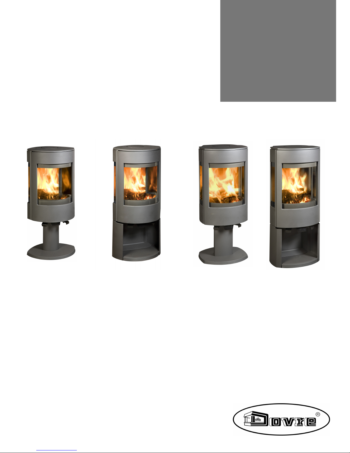
ASTRO 3MFP
ASTRO 3MFWB
ASTRO 4MFP
ASTRO 4MFWB
03.27662.100 - 03/2013
Page 2

2
Wijzigingen op grond van technische verbeteringen voorbehouden
Inhoudsopgave
Inleiding 3
Conformiteitsverklaring 3
Veiligheid 4
Installatiecondities 4
Algemeen 4
Schoorsteen 4
Ventilatie van deruimte 5
Vloer en wanden 6
Productbeschrijving 6
Installatie 6
Algemene voorbereiding 6
Schoorsteenaansluitingvoorbereiden 8
Buitenluchtaansluiting voorbereiden 9
Plaatsen enaansluiten 11
Gebruik 11
Eerste gebruik 11
Brandstof 11
Aanmaken 12
Stoken met hout 12
Stoken met bruinkoolbriketten 13
Stoken met antracietkolen 13
Regeling verbrandingslucht 13
Doven van het vuur 14
Ontassen 14
Nevel en mist 15
Eventueleproblemen 15
Onderhoud 15
Schoorsteen 15
Schoonmaken en ander regelmatig onderhoud15
Bijlage 1: Technische gegevens 18
Bijlage 2: Afmetingen 20
Bijlage 3: Afstand tot brandbaar materiaal 24
Bijlage 4: Diagnoseschema 28
Index 29
Page 3
Wijzigingen op grond van technische verbeteringen voorbehouden
3
Inleiding
Geachte gebruiker,
Met de aankoopvan dit verwarmingstoestel van
DOVRE heeft u gekozen vooreen kwaliteitsproduct.
Dit product maakt deel uit van een nieuwe generatie
energiezuinige en milieuvriendelijke
verwarmingstoestellen. Deze toestellenmaken
optimaal gebruik van zowel convectiewarmte als
stralingswarmte.
Uw DOVRE toestel is geproduceerdmet de
modernste productiemiddelen. Mocht er
onverhoopt toch iets mankerenaan uw toestel, dan
kunt u altijd een beroep doen opde DOVRE
service.
Het toestel mag niet gewijzigd worden; gebruik
steeds originele onderdelen.
Het toestel is bedoeld voorplaatsing in een
woonruimte. Het moet hermetisch worden
aangesloten op een goedwerkendeschoorsteen.
Wij adviseren u het toestel te laten installeren door
eenbevoegd installateur.
DOVRE kan niet aansprakelijk wordengesteld
worden voor problemen of schade door een
onjuiste installatie.
Bij installatie en gebruik moeten de hierna
beschreven veiligheidsvoorschriften in acht
worden genomen.
In deze handleiding leest u hoe u het DOVRE
verwarmingstoestel op een veilige manier installeert,
gebruikt en onderhoudt. Als u aanvullende informatie
of technische gegevens wilt of eeninstallatieprobleem heeft, neemt u dan eerst contact op met uw
leverancier.
© 2013 DOVRE NV
Conformiteitsverklaring
Notified body: 1625
Hierbij verklaart
Dovre nv, Nijverheidsstraat 18 B-2381 Weelde,
dat houtkachel Astro 3MFP, Astro 3MFWB, Astro
4MFP en Astro 4MFWB conform EN 13240
geproduceerd zijn.
Weelde01-03-2013
In het kader van een continueproductverbetering,
kunnen specificaties van het geleverde toestel
afwijken van de beschrijving in deze brochure, zonder
voorafgaandekennisgeving.
DOVRE N.V.
Nijverheidsstraat 18 Tel : +32 (0) 14 65 91 91
B-2381 Weelde Fax : +32 (0) 14 65 90 09
België E-mail : info@dovre.be
Page 4
4
Wijzigingen op grond van technische verbeteringen voorbehouden
Veiligheid
Let op! Alle veiligheidsvoorschriften moeten
strikt worden nageleefd.
Lees aandachtig de instructies voor installatie,
gebruik enonderhoud die met het toestel zijn
meegeleverd, voordat u het toestel in gebruik
neemt.
Het toestel moet worden geïnstalleerd
overeenkomstig de wetgeving envoorschriften
van uw land.
Alle lokale bepalingen en de bepalingen die
betrekking hebbenop nationale en Europese
normen moeten worden nageleefd bij het
installeren van het toestel.
Laat het toestel bij voorkeur installerendoor
eenbevoegd installateur. Deze is op de hoogte
van de geldende bepalingenen voorschriften.
Het toestel is ontworpen voor
verwarmingsdoeleinden. Alle oppervlaktes,
inclusief het glas en de aansluitbuis kunnen
zeer heet worden (meer dan 100°C)! Gebruik
voor debediening een 'koude hand' of een
hittebestendigehandschoen. Zorg voor
voldoende afscherming als jonge kinderen,
mindervaliden en ouderen zich in de nabijheid
van het toestel bevinden.
Veiligheidsafstanden tot brandbaarmateriaal
moeten strikt worden aangehouden.
Plaats geengordijnen, kleren, wasgoed of
andere brandbarematerialen bovenop of in de
nabijheidvan het toestel.
Gebruik tijdens het gebruik van uw toestel
geen licht ontvlambare of explosieve stoffen in
de nabijheid van het toestel.
Voorkom schoorsteenbranddoor regelmatig de
betreffendeschoorsteen te laten reinigen.
Stook het toestel nooit met open deur.
Bij schoorsteenbrand: sluit de luchtinlaten van
het toestel en waarschuw de brandweer.
Als het glas van het toestel is gebroken of
gebarsten, moet dit glas worden vervangen
voordat u het toestel opnieuw in gebruik neemt.
Zorg voor voldoende ventilatie van deruimte
waar het toestel wordt geplaatst. Bij
onvoldoende ventilatie vindt onvolledige
verbranding plaats, waardoor zich giftige
gassen in deruimte kunnen verspreiden. Zie
het hoofdstuk "Installatiecondities" voor meer
informatie over ventilatie.
Installatiecondities
Algemeen
Het toestel moet worden aangesloten opeen goed
werkende schoorsteen.
Voor de aansluitmaten: zie de bijlage"Technische
gegevens".
Informeer bij debrandweer en/of
verzekeringsmaatschappij naar eventuele
specifieke vereisten envoorschriften.
Schoorsteen
De schoorsteen is nodig voor:
Het afvoerenvan de verbrandingsgassen door
natuurlijke trek.
De warme lucht in de schoorsteen is lichter
dande buitenlucht en stijgt daarom.
Het aanzuigen van lucht, nodig voor de verbranding
van de brandstof in het toestel.
Een niet goed werkende schoorsteen kan tijdens het
openenvan de deur rookterugslag geven. Schade
ontstaan door rookterugslag is uitgesloten van
garantie.
Sluit niet meerdere toestellen (bijvoorbeeld ook
nogeen centraleverwarmingsketel) op
dezelfde schoorsteen aan, tenzij lokale of
nationale regelgevinghierin voorziet. Zorg in
ieder geval bij twee aansluitingen dat het
hoogteverschil tussen de aansluitingen
minimaal 200 mm bedraagt.
Vraag uw installateur om advies over de schoorsteen.
Raadpleegde Europese norm EN13384 voor een
juiste berekening van de schoorsteen.
Page 5
Wijzigingen op grond van technische verbeteringen voorbehouden
5
De schoorsteen moet aan de volgende voorwaarden
voldoen:
De schoorsteen moet gemaakt zijn van vuurvast
materiaal, bij voorkeur keramiek of roestvrij staal.
De schoorsteen moet luchtdicht en goedgereinigd
zijn en voldoendetrek garanderen.
Een trek/onderdruk van 15-20Pa tijdens
normale belasting is ideaal.
De schoorsteen moet - vertrekkend van de uitgang
van het toestel - zo verticaal mogelijk lopen.
Richtingsveranderingen en horizontalestukken
verstoren de afvoer van verbrandingsgassen en
veroorzakenmogelijk roetophoping.
De binnenmaten mogen niet te groot zijn, om te
voorkomen dat de verbrandingsgassen te sterk
afkoelen waardoorde trek minderwordt.
De schoorsteen moet bij voorkeur dezelfde
diameter hebben als de aansluitkraag.
Voor de nominale diameter: zie de bijlage
"Technische gegevens". Als het rookkanaal
goed is geïsoleerd, kan de diameter eventueel
wat groter zijn (maximaal tweemaal de sectie
van de aansluitkraag).
De sectie (oppervlakte) van het rookkanaal moet
constant zijn. Verwijdingen en (vooral)
vernauwingen verstoren de afvoervan
verbrandingsgassen.
Bij toepassing van een regenkap/afvoerkap op de
schoorsteen: let erop dat de kap niet de uitmonding
van de schoorsteen vernauwt en dat de kap niet de
afvoer van verbrandingsgassen belemmert.
De schoorsteen moet uitmonden in eenzonedie
niet wordt verstoord door omliggende gebouwen,
vlakbijstaande bomen of andere hindernissen.
Het schoorsteengedeelte buiten de woning moet
geïsoleerd zijn.
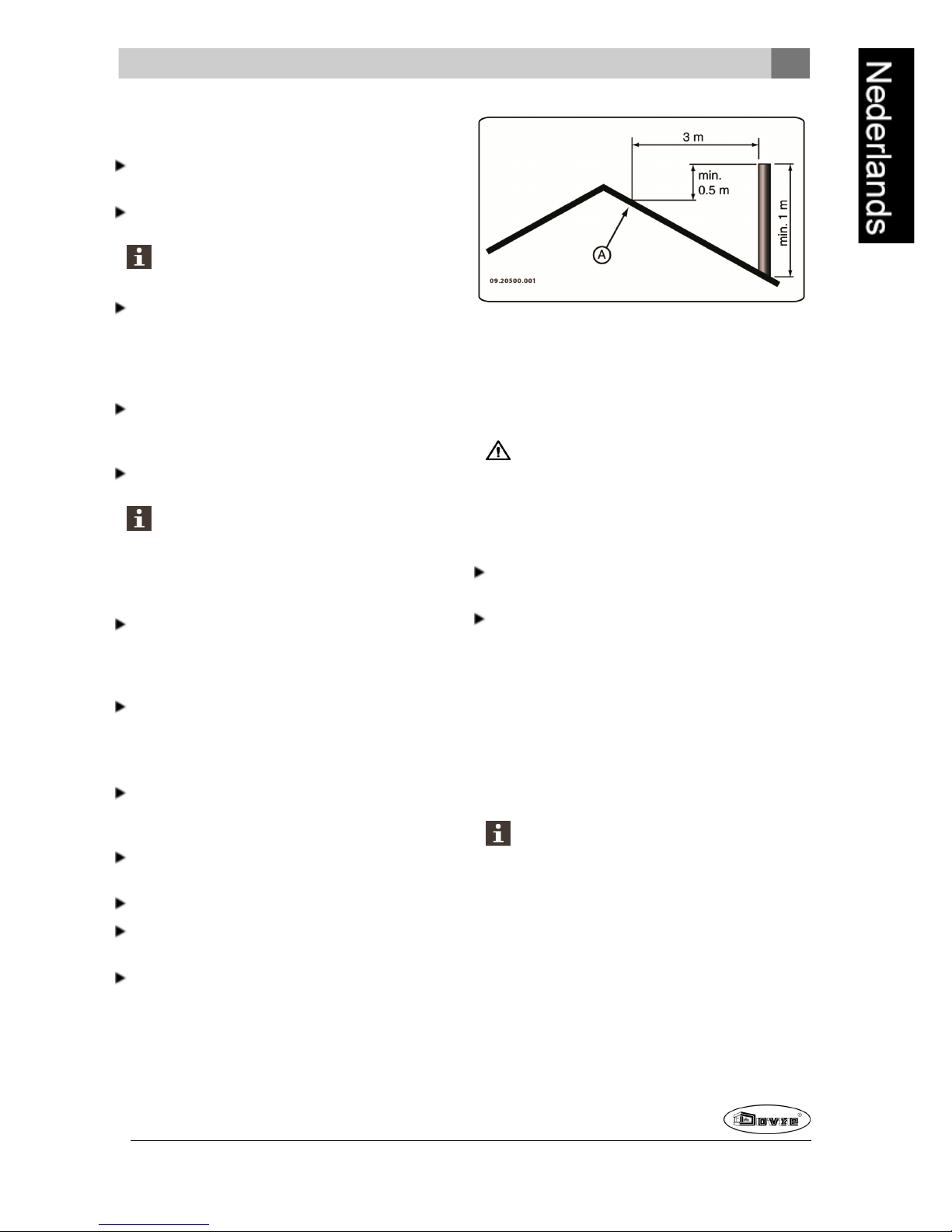
De schoorsteen moet minimaal 4meterhoog zijn.
Als vuistregel geldt: 60cm boven denok van het
dak.
Als de nok van het dak meer dan 3meter is
verwijderd van de schoorsteen: houd de maten aan
die in de volgendefiguur zijn aangegeven. A = het
hoogste punt van het dak binnen een afstand van
3meter.
Ventilatie van de ruimte
Voor een goede verbranding heeft het toestel lucht
(zuurstof) nodig. Die lucht wordt via regelbare
luchtinlaten aangevoerd vanuit de ruimte waar het
toestel is geplaatst.
Bij onvoldoende ventilatie vindt onvolledige
verbranding plaats, waardoor zich giftige
gassen in deruimte kunnen verspreiden.
Een vuistregel is dat de luchttoevoer5,5cm²/kW
moet zijn. Extra ventilatie is nodig:
Als het toestel in eenruimte staat die goedis
geïsoleerd.
Als er mechanische ventilatie is, bv een centraal
afzuigsysteem of een afzuigkapin een open
keuken.
U kunt voor extra ventilatie zorgen door een
ventilatierooster in debuitenmuur te laten plaatsen.
Zorg dat andereluchtverbruikende apparaten (zoals
eenwasdroger, ander verwarmingstoestel of
badkamerventilator) eeneigen buitenluchtaanvoer
hebben, of zijn uitgeschakeldwanneeru het toestel
stookt.
U kunt het toestel ook aansluiten op
buitenluchtaanvoer. Extra ventilatie is dan niet
nodig.
Page 6
6
Wijzigingen op grond van technische verbeteringen voorbehouden
Vloer en wanden
De vloer waarop het toestel wordt geplaatst, moet
voldoende draagvermogen hebben. Voor het gewicht
van het toestel: zie de bijlage"Technische gegevens".
Bescherm een brandbare vloer door middel van
eenonbrandbare vloerplaat tegen warmteuitstraling. Zie de bijlage"Afstandtot
brandbaar materiaal".
Verwijder brandbaar materiaal zoals linoleum,
tapijt, enzovoorts onderde onbrandbare
vloerplaat.
Zorg voor voldoende afstand tussen het toestel
en brandbare materialen zoals houtenwanden
en meubels.
Ook de aansluitbuis straalt warmte uit. Zorg
voor voldoende afstand of afscherming tussen
de aansluitbuis en brandbare materialen.
De vuistregel voor een enkelwandigebuis is
eenafstand van driemaal de diameter. Als een
bekledingsschelp rond debuis is aangebracht,
is een afstand van eenmaal de diameter
toelaatbaar.
Een vloerkleed moet minimaal 80cm van het
vuur verwijderd zijn.
Bescherm een brandbare vloer voor de kachel
met behulp van een onbrandbarevloerplaat
tegeneventueel uitvallendeassen. De
vloerplaat moet voldoen aan nationale normen.
Voor de afmetingen van de onbrandbare
vloerplaat: zie de bijlage "Afstand tot brandbaar
materiaal".
Voor verdereeisen in verband met
brandveiligheid: zie de bijlage "Afstand tot
brandbaar materiaal".
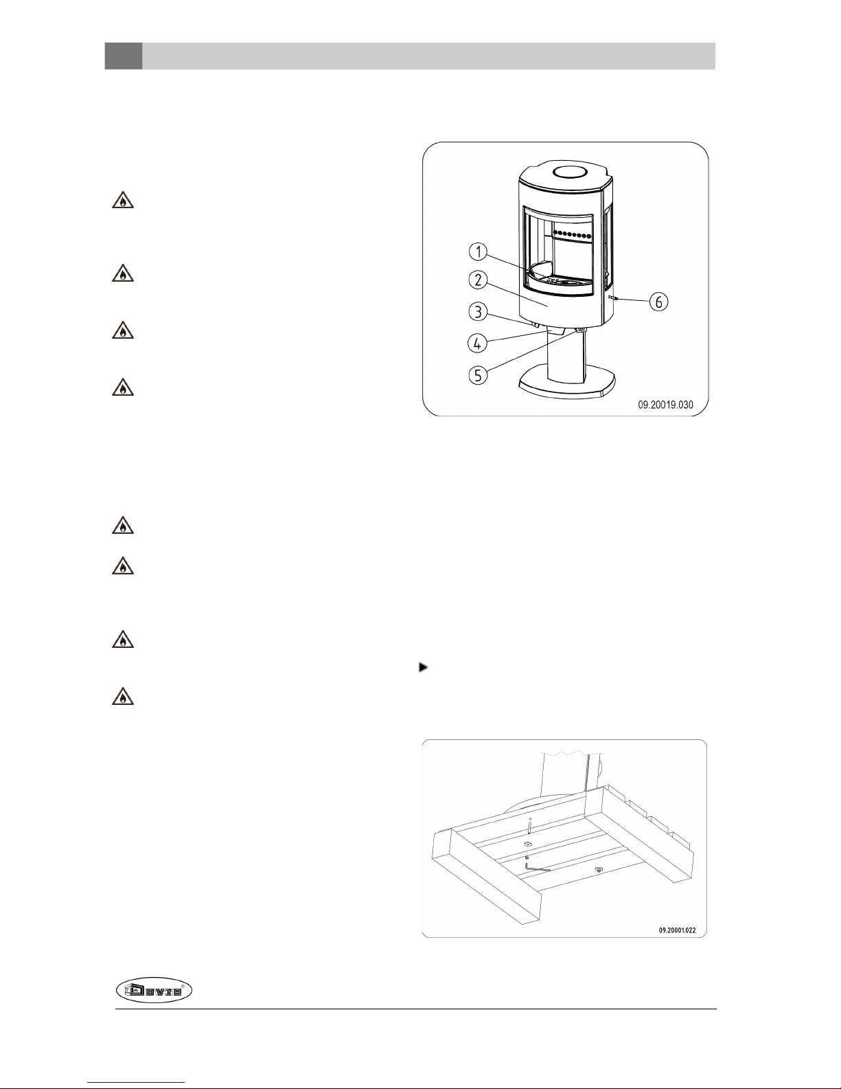
Productbeschrijving
1. Stookrooster
2. Deur
3. Primaire luchtschuif
4. Deurgrendel
5. Secundaire luchtschuif
6. Schudstang
Installatie
Algemene voorbereiding
Controleer het toestel onmiddellijk bij ontvangst op
(transport)schadeen eventuele anderegebreken.
Het toestel is aan de onderkant met schroeven op
de pallet gemonteerd.
Page 7
Wijzigingen op grond van technische verbeteringen voorbehouden
7
Als u (transport)schade of gebreken hebt
geconstateerd, neem het toestel dan niet in
gebruik enstel de leverancier op de hoogte.
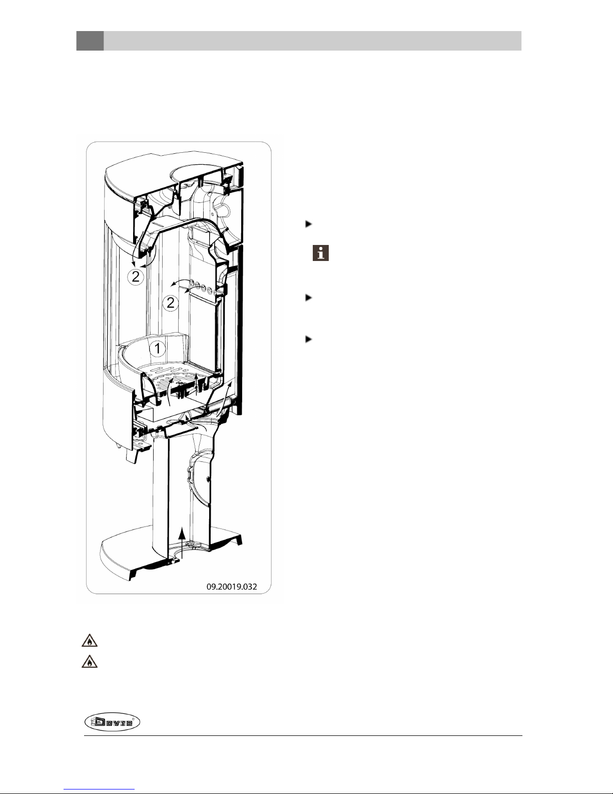
Verwijder de demontabeleonderdelen (vuurvaste
binnenplaten, stookrooster, topplaat, aslade) uit
het toestel voordat u het toestel gaat installeren.
Door demontabeleonderdelen te verwijderen,
kunt u het toestel gemakkelijker verplaatsen en
beschadiging voorkomen.
Let bij het verwijderen van demontabele
onderdelen op hun oorspronkelijke positie, om
ze later weer op de juiste plaats te kunnen
aanbrengen.
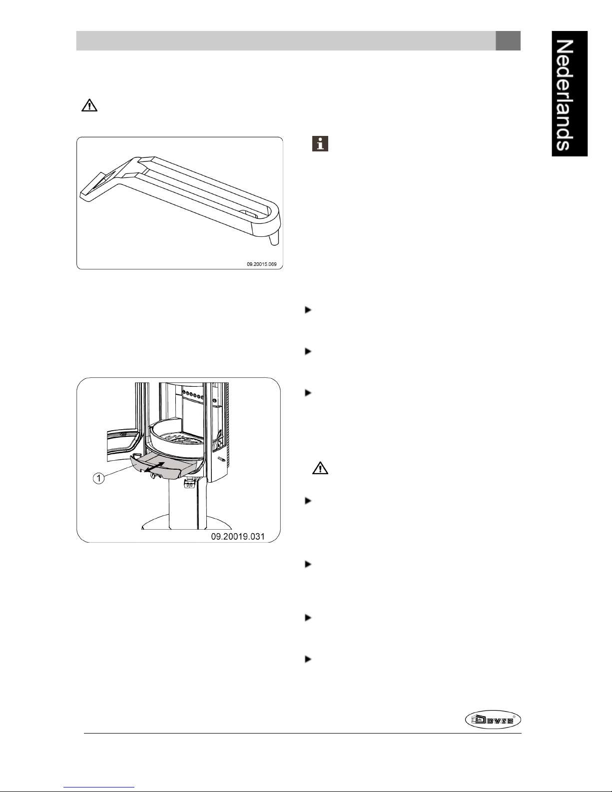
1. Open dedeur; zie volgende figuur.
2. Verwijder de vuurvaste binnenplaten; zie volgende
figuur.
Vermiculite binnenplaten zijn licht van gewicht
en bij levering meestal okerkleurig. Zij isoleren
de verbrandingskamer zodat de verbranding
beteris. Gietijzeren binnenplaten beschermen
de verbrandingskamer en geven warmte door
aande omgeving.
1
2
7
4
7
5
3
6
09.20019.033
Uitneembare binnendelen
astro3 series
1 03.77099.002 Vuurkorf voor
2 03.77400.002 Vuurkorf links
3 03.77401.002 Vuurkorf rechts
4 03.08365.002 Binnenplaat
5 03.61115.100 Schudrooster
6 03.66532.100 Stookrooster
astro4 series
1 03.77099.002 Vuurkorf voor
2 03.77402.002 Vuurkorf links
3 03.77403.002 Vuurkorf rechts
4 03.08365.002 Binnenplaat
5 03.61115.100 Schudrooster
6 03.66532.100 Stookrooster
7 03.35210.000 Hoekstuk
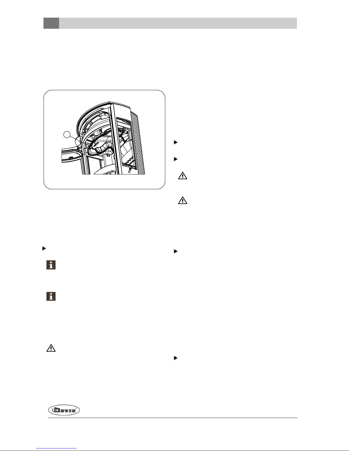
4. Verwijder de aslade; zie volgendefiguur.
Page 8
8
Wijzigingen op grond van technische verbeteringen voorbehouden
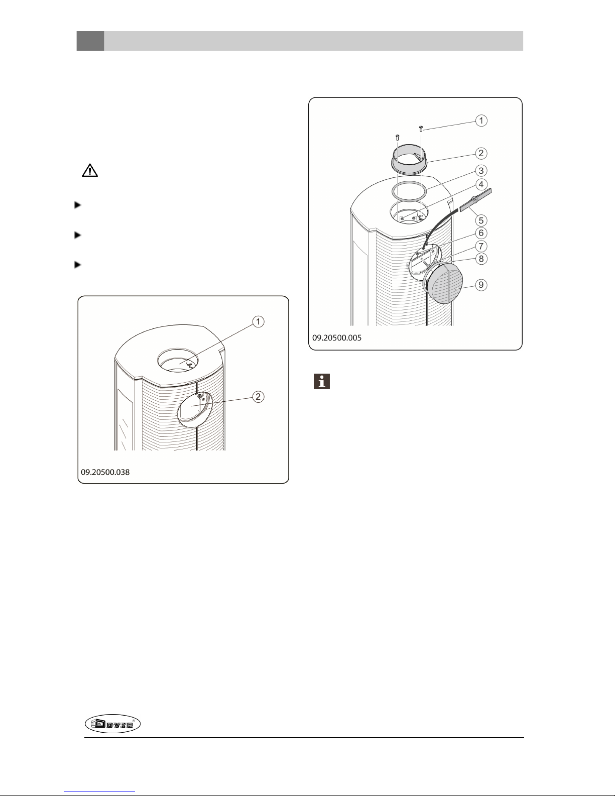
Schoorsteenaansluiting
voorbereiden
Bij het aansluitenvan het toestel op een schoorsteen
hebt u de keuze uit aansluitingaan de bovenzijde of
aande achterzijde van het toestel.
Bij levering van het toestel is de aansluitingop
de achterzijde open gelaten.
De uitgangdie u niet wilt gebruiken, sluit u af met
het bijbehorende meegeleverde afsluitdeksel.
Op deuitgang dieu wel wilt gebruiken, monteert u
de bijbehorende meegeleverde aansluitkraag.
Afdichtings- en bevestigingsmaterialenzijn
meegeleverd.
1 Aansluitingaan bovenzijde
2 Aansluitingaan achterzijde
Aansluiten op de bovenzijde
1. Verwijder de topplaat.
De topplaat kan gewoonvan het toestel
worden afgenomen.
2. Breng bij de uitgang aan de bovenzijde
afdichtingskit aan op het contactvlak waarop de
aansluitkraag komt.
3. Monteer de aansluitkraag met de
bevestigingsmaterialen.
4. Breng bij de uitgang aan de achterzijde
afdichtingskit aan op het contactvlak waarop het
afsluitdeksel komt.
5. Monteer het afsluitdeksel met de
bevestigingsmaterialen.
Page 9
Wijzigingen op grond van technische verbeteringen voorbehouden
9
Aansluiten op de achterzijde
1. Verwijder de topplaat.
De topplaat kan gewoonvan het toestel
worden afgenomen.
2. Breng bij de uitgang aan de bovenzijde
afdichtingskit aan op het contactvlak waarop het
aflsuitdeksel komt.
3. Monteer het afsluitdeksel met de
bevestigingsmaterialen.
4. Breng aan de achterzijde afdichtingskit aan op het
contactvlak waarop deaansluitkraag komt.
5. Monteer de aansluitkraag met de
bevestigingsmaterialen.
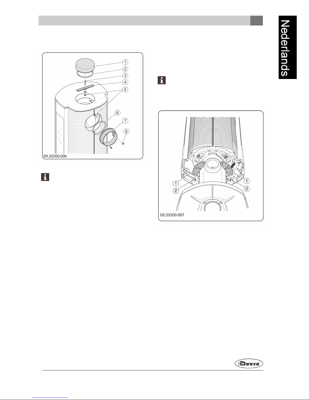
Buitenluchtaansluiting
voorbereiden
Als het toestel wordt geplaatst in eenruimte die
onvoldoende is geventileerd, kunt u eenaansluitset
voor het aanvoerenvan buitenlucht op het toestel
monteren. Sommige van de bestaandeluchtinlaten op
het toestel moet u danafsluiten met meegeleverd
afdekmateriaal. Het is aan te raden een aansluitset
toe te passen die voorzien is van een klep die u kunt
sluiten als het toestel niet in gebruik is.
De luchtaanvoerbuis heeft een diameter van 100mm.
Bij toepassing van een gladde buis mag deze buis
maximaal 12 meter lang zijn. Bij gebruik van
hulpstukken zoals bochten moet u per hulpstuk de
maximale lengte (12 meter) met 1 meter verminderen.
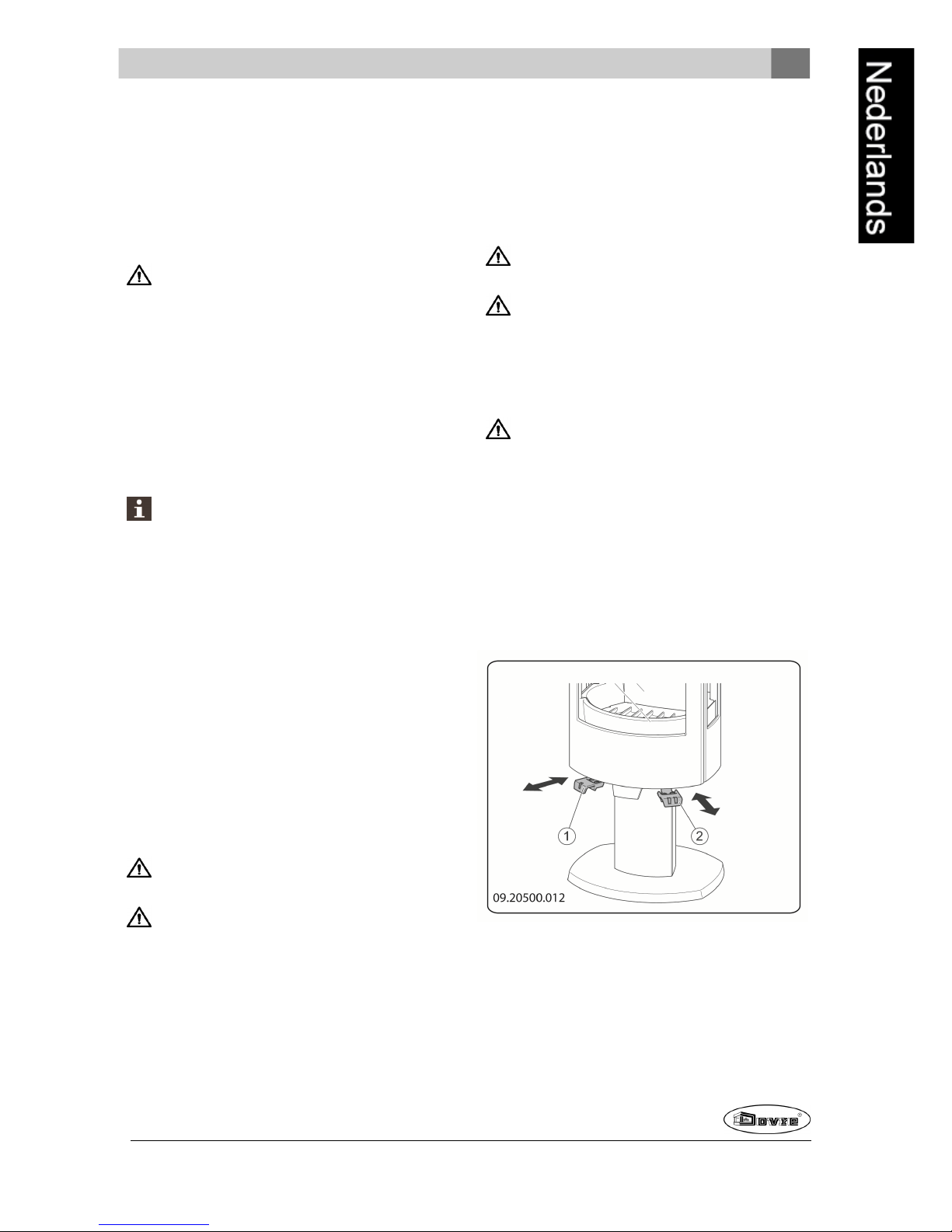
1. Sluit de luchtinlaat in de bodemplaat af met de
gietijzeren afdekplaatjes (1) en schroeven (2); zie
volgende figuur.
Door deluchtinlaat in de bodemplaat af te
sluiten voorkomt u dat lucht uit de onvoldoende
geventileerde ruimte wordt gebruikt voor de
verbranding.
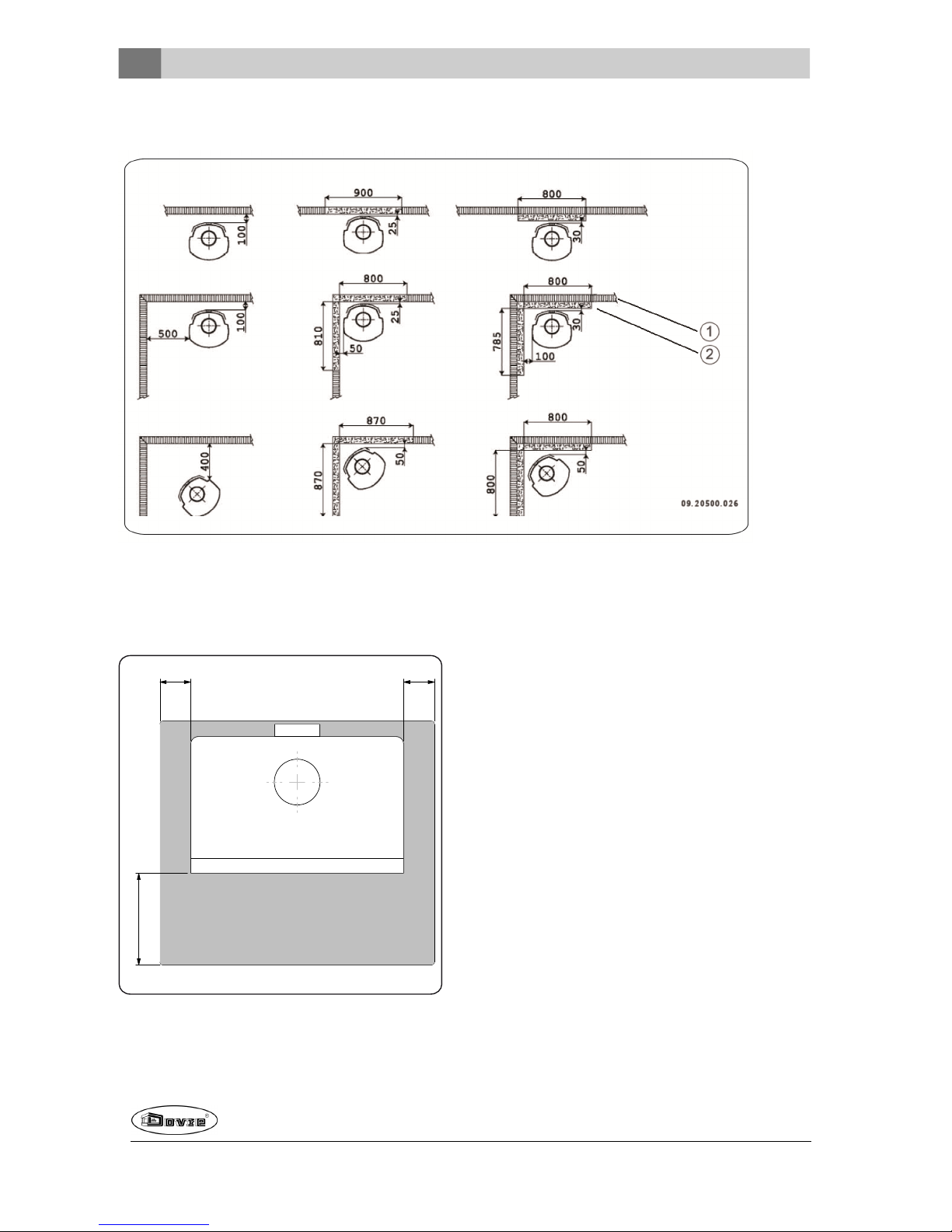
2. Voor buitenluchtaansluiting via de vloer:
a. Maak een aansluitgat in de vloer; raadpleeg
'Bijlage 2, Afmetingen' voor de juiste positie
van het aansluitgat.
b. Schuif een rechte luchtaanvoerbuis op de
aansluitkraag van het toestel, zodanig dat
deze niet kan verschuiven; zie volgende
figuur.
Page 10

10
Wijzigingen op grond van technische verbeteringen voorbehouden
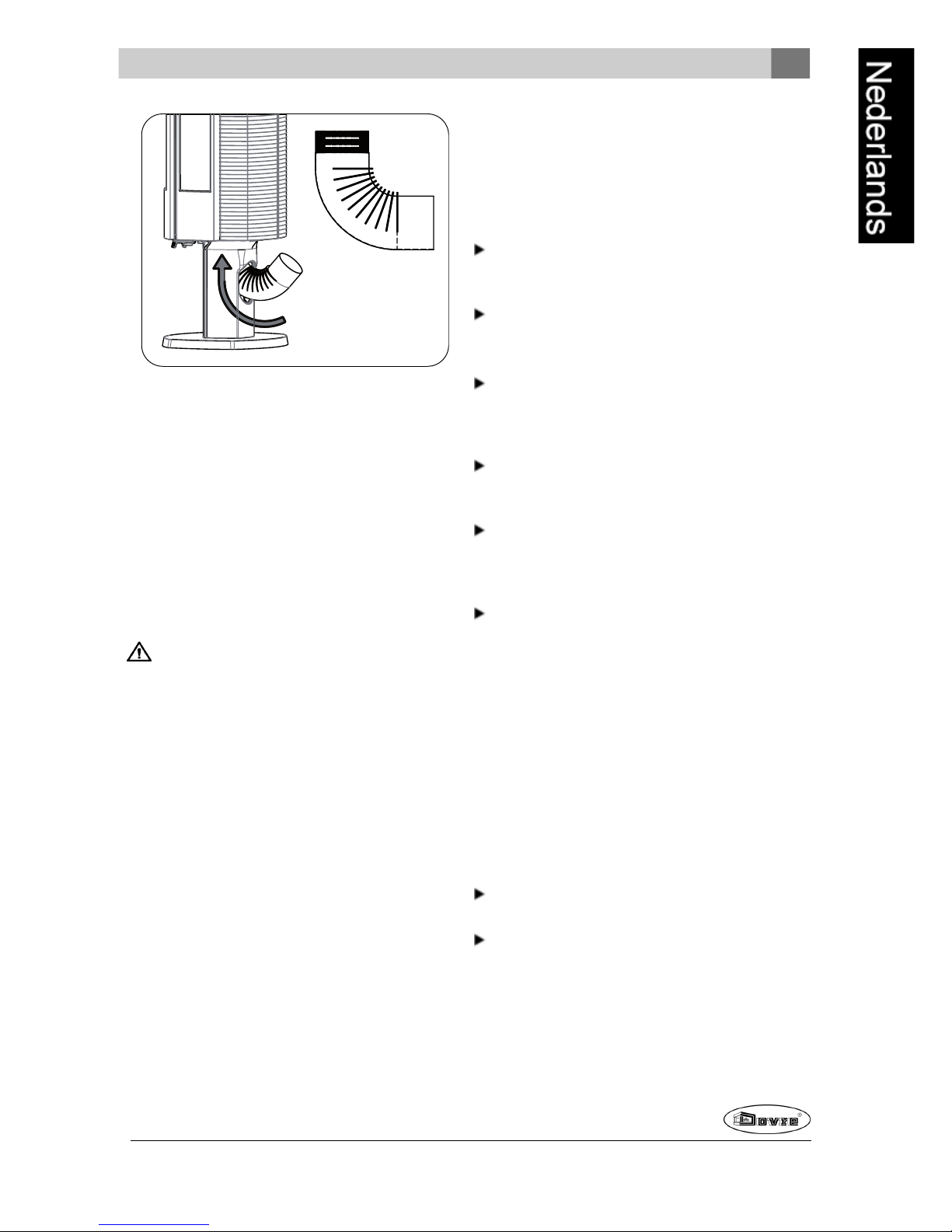
3. Voor buitenluchtaansluiting via de achterkant van
het toestel:
a. Maak een opening in de sokkel of het houtvak
door de afdekplaat aan de achterkant van de
sokkel of het houtvak te verwijderen; zie
volgende figuren.
Afhankelijk van de uitvoering van het
toestel is deafdekplaat is met verende
clips bevestigd of met een sluitplaatje.
Gebruik bij eenveerbevestiging een
schroevendraaier om de afdekplaat uit zijn
sponning te tillen.
b. Sluit eenzogenaamde'elleboog' hermetisch
aanop de opening in de sokkel of het houtvak,
zodanig dat deze niet kan verschuiven; zie
volgende figuur.
Afhankelijk van de uitvoering van de
elleboogkan dehoogtemaat voor de
aansluiting door de muur verschillen.
Page 11
Wijzigingen op grond van technische verbeteringen voorbehouden
11
EN 1856-2
DIN 1298
Ø100 - 90°
09-20001-017
Plaatsen en aansluiten
1. Zet het toestel op de juiste plaats, vlak en
waterpas.
2. Sluit het toestel hermetisch aan opde
schoorsteen.
3. Bij buitenluchtaansluiting: sluit de aanvoer van
buitenlucht aan op de aansluitkraag binnenin de
sokkel of het houtvak van het toestel of op
gemonteerdeelleboog.
4. Plaats alle gedemonteerde onderdelenop de juiste
plaats terug in het toestel.
Laat het toestel nooit branden zonder de
vuurvaste binnenplaten.
Het toestel is nu klaar voorgebruik.
Gebruik
Eerste gebruik
Wanneer u het toestel voorhet eerst gebruikt, stook
het danenkele uren flink door. Hierdoor zal de
hittebestendigelak uitharden. Hierbij kan wel wat rook
en geurhinder ontstaan. Zet eventueel in de ruimte
waar het toestel staat de ramen endeuren even open.
Brandstof
Het toestel is geschikt voor het stoken van natuurlijk
hout; gezaagden gekloofd en voldoende droog.
Daarnaast is het toestel ook geschikt voor het stoken
van bruinkoolbriketten en antracietkolen.
Gebruik geen andere brandstoffen, want die kunnen
leiden tot ernstige schadeaan het toestel.
De volgende brandstoffen mag u niet gebruiken omdat
zij het milieu vervuilen, en omdat zij het toestel en de
schoorsteen sterk vervuilen waardoor
schoorsteenbrand kan ontstaan:
Behandeld hout, zoals sloophout, geverfd hout,
geïmpregneerd hout, verduurzaamdhout, multiplex
en spaanplaat.
Kunststof, oud papier enhuishoudelijk afval.
Hout
Gebruik bij voorkeur hard loofhout zoals eik, beuk,
berk en fruitbomenhout. Dit hout brandt langzaam
met rustige vlammen. Naaldhout bevat meerhars,
brandt sneller en geeft meer vonken.
Gebruik gedroogdhout met een vochtpercentage
van maximaal 20%. Hiervoor moet het hout
minstens 2 jaar zijn gedroogd.
Zaaghet hout op maat en klief het als het nog vers
is. Vers hout klieft gemakkelijker en gekloven hout
droogt beter. Bewaar het hout onder een afdek
waar dewind vrij spel heeft.
Gebruik geen nat hout. Nat hout geeft geen warmte
omdat alle energie gaat zitten in het verdampen
van vocht. Dit geeft veel rook en roetaanslag op de
deur van het toestel en in deschoorsteen. De
waterdamp condenseert in het toestel en kan langs
naden uit het toestel lekken en zwarte vlekken op
de vloergeven. De waterdamp kan ook in de
schoorsteen condenseren encreosoot vormen.
Creosoot is zeer brandbaar en kan
schoorsteenbrand veroorzaken.
Bruinkoolbriketten
Bruinkoolbriketten hebbenongeveer dezelfde
brandeigenschappen als hout.
Zorg voor een goed houtskoolbedvoordat u
bruinkoolbriketten gaat stoken.
Volg voorhet aanmaken van de haard de
instructies in de paragraaf "Aanmaken".
Antracietkolen
Antracietkolen worden ingedeeld in categorieën op
grond van kenmerken, soms bij wet bepaald, zoals
het percentage vluchtige stoffen. Het asgehalte van
Page 12
12
Wijzigingen op grond van technische verbeteringen voorbehouden
antracietkolen ligt tussen de 3% en 13%. Hoe lager
het asgehalte hoe hoger de stookwaarde en hoe
minder vaak u hoeft te ontassen.
Gebruik bij voorkeur categorie A antracietkolen met
eenlaag asgehalte.
Gebruik het aanbevolen formaat 12/22 of 20/30.
Volg voorhet aanmaken van de haard de
instructies in de paragraaf "Aanmaken".
Aanmaken
U kunt controleren of de schoorsteen voldoende trek
heeft door boven de vlamplaat eenprop krantenpapier
aante steken. Bij een koudeschoorsteen is er vaak
onvoldoende trek in de schoorsteen enkan errook in
de kamer komen. Door het toestel op dehier
beschreven manier aan te maken, voorkomt u dit
probleem.
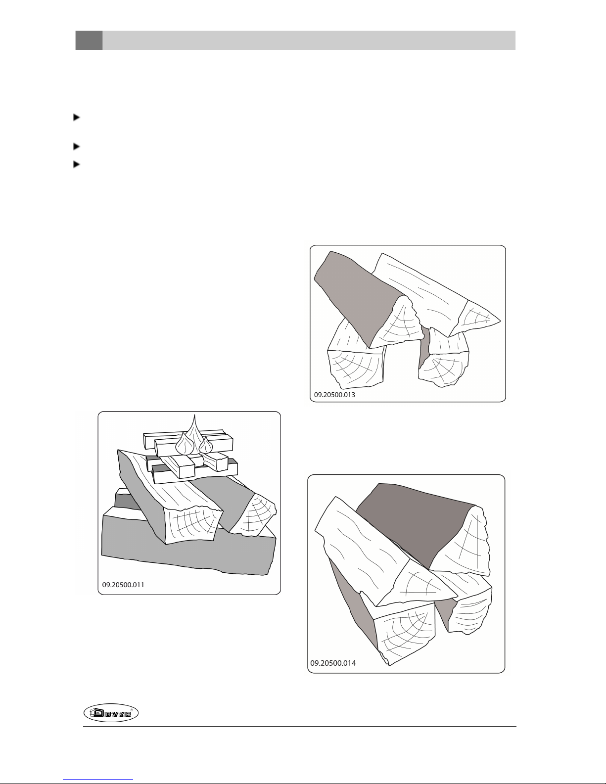
1. Stapel twee lagen middelgrote houtblokken
kruislings op elkaar.
2. Stapel bovenop de houtblokken twee lagen
aanmaakhoutjes kruislings op elkaar.
3. Leg eenaanmaakblokje tussen de onderste laag
aanmaakhoutjes en steek het aanmaakblokje aan
volgens de instructies op de verpakking.
4. Sluit de deur van het toestel en zet de primaire
luchtinlaat en de secundaireluchtinlaat van het
toestel open; zie paragraaf 'Regeling
verbrandingslucht'.
5. Laat het aanmaakvuur flink doorbranden totdat het
eengloeiend houtskoolbedis geworden. Hierna
kunt u een volgende vulling doen enhet toestel
gaan regelen; zie de paragraaf "Stoken met hout".
Stoken met hout
Nadat u de instructies voorhet aanmaken hebt
gevolgd:
1. Open langzaam de deur van het toestel.
2. Verdeel het houtskoolbed gelijkmatig over de
stookvloer.
3. Stapel enkele houtblokken op het houtskoolbed.
Losse stapeling
Bij een losse stapelingverbrandt het hout vlug omdat
de zuurstof elk stuk hout gemakkelijk kan bereiken.
Gebruik eenlosse stapeling als u kort wilt stoken.
Compacte stapeling
Page 13
Wijzigingen op grond van technische verbeteringen voorbehouden
13
Bij een compacte stapeling verbrandt het hout
langzamer omdat de zuurstof maar enkele stukken
hout kan bereiken. Gebruik een compacte stapeling
als u langer wilt stoken.
4. Sluit de deur van het toestel.
5. Sluit de primaire luchtinlaat en laat de secundaire
luchtinlaat open staan.
Vul het toestel voor maximaal een derde.
Stoken met bruinkoolbriketten
Bruinkoolbriketten branden op nagenoegdezelfde
manier als hout. Zorg met behulp van deprimaire
luchtinlaat voor voldoendeluchttoevoer onder het
vuur. Zie verder deparagraaf "Stoken met hout".
Het branden van bruinkoolbriketten geeft veel as.
Verwijder de overtollig as regelmatig. Zie de paragraaf
"Ontassen" voor instructies.
Voor de eigenschappen en het gebruik van de
bruinkoolbriketten: raadpleeguw leverancier
van de bruinkoolbriketten of zie de verpakking
van de bruinkoolbriketten.
Nadat u de instructies voorde aanmaak hebt gevolgd:
1. Open langzaam de deur van het toestel.
2. Verdeel het houtskoolbed gelijkmatig over de
stookvloer.
3. Leg de bruinkoolbriketten op het houtskoolbed.
4. Sluit de deur.
5. Ontas regelmatig de stookvloer door middel van
het schudrooster. Gebruik voorde bedieningvan
de schudstang de bijgeleverde koude hand.
Stoken met antracietkolen
Sluit bij het stoken van antracietkolenaltijd de
secundaire luchtschuif.
Zet de brandstofkeuze luchtklep in de gesloten
stand.
Nadat u de instructies voorde aanmaak hebt gevolgd:
1. Zet deprimaire luchtschuif volledig open.
2. Open langzaam de deur van het toestel.
3. Verdeel het houtskoolbed gelijkmatig over de
stookvloer.
4. Verspreideen schep kolen op het houtskoolbed en
wacht met de volgende schep tot de kolen gaan
gloeien.
5. Voeg nu meer kolen toe.
Let op dat u het vuur niet dooft door in een keer
te veel kolen toe te voegen.
U heeft de maximale bijvulling bereikt als de
gloed van de vorige vulling nog net zichtbaar is.
6. Sluit de deur.
7. Laat de kolen enige minuten goed doorbrandenen
regel de luchttoevoer met de primaire luchtschuif.
Als de vuurkorf of de gietijzeren lamellen rood
beginnen te gloeien, bent u te hard aan het
stoken.
8. Ontas regelmatig de stookvloer door middel van
het schudrooster. Gebruik voorde bedieningvan
de schudstang de bijgeleverde koude hand.
Regeling verbrandingslucht
Het toestel heeft diverse voorzieningen voor de
luchtregeling; zie volgendefiguur.
1.
Is de primaireluchtschuif en is geopendin
uitgetrokken positie en gesloten in naar
achter geschoven positie.
2.
Is de secundaireluchtschuif en is geopend
in uitgetrokken positie en gesloten in naar
achter geschovensitie
Page 14
14
Wijzigingen op grond van technische verbeteringen voorbehouden
De primaire luchtschuif regelt de lucht onder het
rooster (1); zie volgende figuur.
De secundaire luchtschuif regelt de lucht voor het glas
en deluchtgaatjes in de achterwand (2).
Adviezen
Stook nooit met open deur.
Stook het toestel regelmatig flink door.
Als u langdurig op lage stand stookt, kan zich
in de schoorsteen een afzetting vormen van
teer encreosoot. Teeren creosoot zijn zeer
brandbaar. Als de afzetting van deze stoffen te
groot wordt, kan bij een plotselinge hoge
temperatuur een schoorsteenbrandontstaan.
Door regelmatig flink doorstoken, verdwijnen
eventuele afzettingen van teer encreosoot.
Daarnaast kan zich bij te laag stoken teer
afzetten op deruit en deur van het toestel.
Bij een milde buitentemperatuur is het dus
beterom het toestel een paar uur intens te
laten branden, dan lange tijd laag te stoken.
Regel deluchttoevoer met de secundaire
luchtinlaat.
De secundaire luchtinlaat belucht niet alleen
het vuur maar ook het glas, zodat het glas niet
snel vervuilt.
Zet de primaireluchtinlaat tijdelijk open als de
luchttoevoer via de secundaire luchtinlaat
onvoldoende is of als u het vuurwilt aanwakkeren.
Regelmatig een kleine hoeveelheid houtblokken
bijvullen is beter dan veel houtblokken tegelijk.
Doven van het vuur
Vul geen brandstof bij en laat de kachel gewoon
uitgaan. Als een vuur wordt getemperd door de
luchttoevoer te verminderen, komen schadelijke
stoffen vrij. Laat daarom het vuurvanzelf uitbranden.
Houd toezicht op het vuurtotdat het goed is gedoofd.
Als het vuur volledig is gedoofd kunnen alle
luchtschuiven worden gesloten.
Ontassen
Na het stoken van hout blijft een relatief kleine
hoeveelheid as over. Dit asbed is een goede isolator
voor destookbodem engeeft een betere verbranding.
Laat daarom gerust een dun laagje as op de
stookbodem liggen.
De luchttoevoerdoor destookbodem mag echter niet
worden belemmerd en ermag zich geen as ophopen
achter een gietijzeren binnenplaat. Verwijder daarom
regelmatig de overtollige as.
Na het stoken van bruinkoolbriketten en
antracietkolen blijft er relatief veel as over. Er mag
zich geen as ophopen onderhet stookrooster en de as
mag nooit de onderkant van het rooster raken. Het
rooster raakt dan oververhit en beschadigd.
Page 15
Wijzigingen op grond van technische verbeteringen voorbehouden
15
1. Gebruik de schudstang om het rooster vrij van
overtollig assen te maken.
Gebruik voor de bediening van de schudstang
de koude hand indien het toestel nogwarm is.
2. Open dedeur van het toestel.
3. Schuif eventuele as-restanten met behulp van het
trekschepje door het rooster.
4. Verwijder de aslade (zie volgende figuur) met
behulp van debijgeleverde handschoen en leeg de
aslade.
5. Plaats de aslade terugen sluit dedeur van het
toestel.
Nevel en mist
Nevel en mist belemmeren de afvoer van rookgassen
door de schoorsteen. Rook kan neerslaanen
stankoverlast geven. Als het niet echt nodig is, kunt u
bij nevel enmist beter niet stoken.
Eventuele problemen
Raadpleegde bijlage"Diagnoseschema" om
eventuele problemen bij het gebruik van het toestel op
te lossen.
Om het nominale vermogenvan het toestel te
halen, moet per45 minuten ongeveer 2 kg
brandstof worden verbrand.
Onderhoud
Volg de onderhoudsinstructies in dit hoofdstuk om het
toestel in goede staat te houden.
Schoorsteen
In veel landen bent u wettelijk verplicht de
schoorsteen te laten controleren en onderhouden.
Aan het begin van het stookseizoen: laat de
schoorsteen vegendoor een erkend
schoorsteenveger.
Tijdens het stookseizoenen nadat de schoorsteen
lange tijd niet is gebruikt: laat de schoorsteen
controleren op roet.
Na afloop van het stookseizoen: sluit de
schoorsteen af met een prop krantenpapier.
Schoonmaken en ander
regelmatig onderhoud
Maak het toestel niet schoon wanneer het nog
warm is.
Maak de buitenkant van het toestel schoon met
eendrogeniet-pluizendedoek.
Na afloop van het stookseizoenkunt u de binnenkant
van het toestel goed schoonmaken:
Verwijder eventueel eerst de vuurvaste
binnenplaten. Zie het hoofdstuk "Installatie" voor
instructies voor het verwijderenen aanbrengen van
binnenplaten.
Maak eventueel deluchtaanvoerkanalen schoon.
Verwijder hiervoor de topplaat. De topplaat ligt los
op het toestel.
Verwijder eventueel de vlamplaat boven in het
toestel en maak deze schoon.
Page 16
16
Wijzigingen op grond van technische verbeteringen voorbehouden
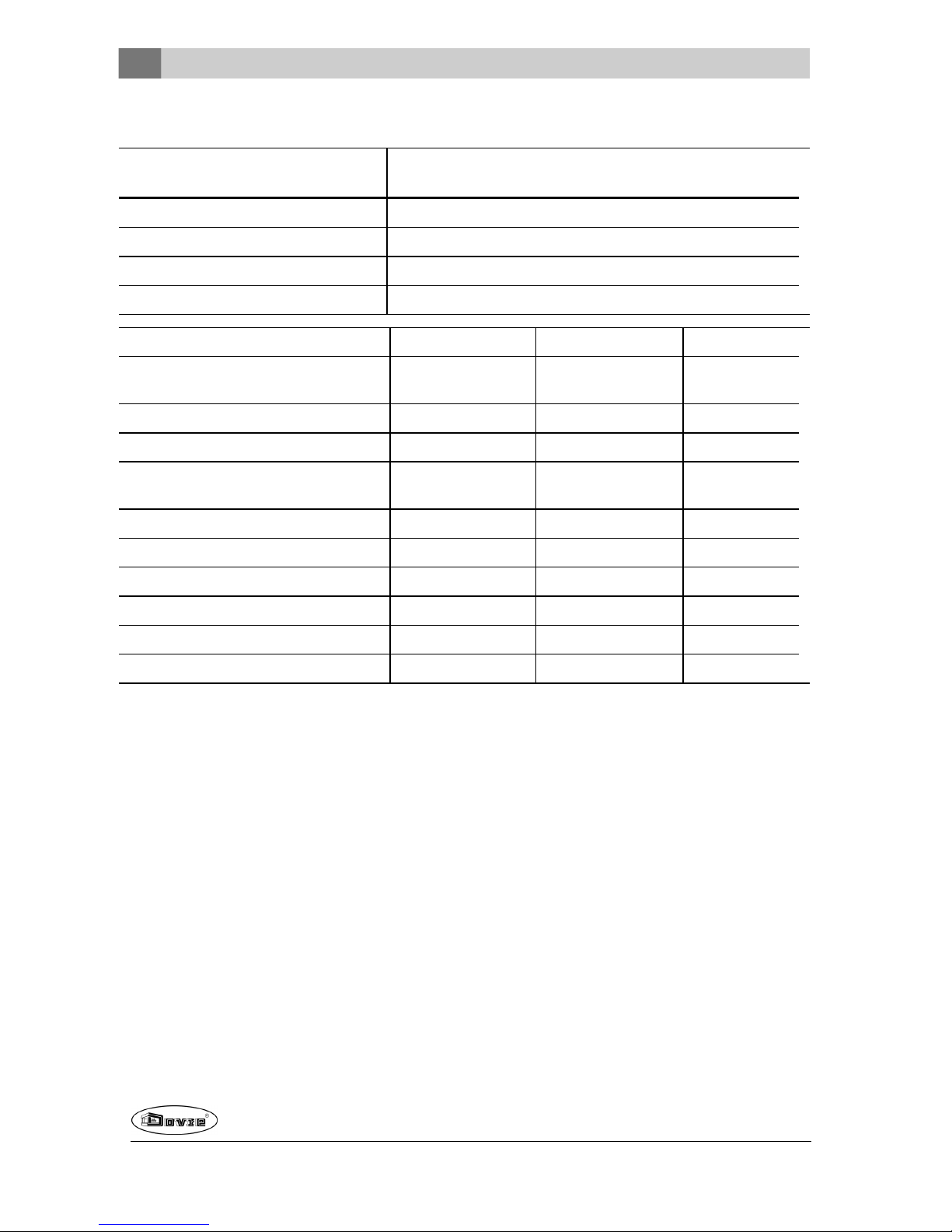
Vlamplaat verwijderen en aanbrengen
Schroef aan de voorzijde van de vlamplaat het
klemplaatje los. Til de vlamplaat van de steunnok en
kantel de vlamplaat uit het toestel. Let op bij het
terugplaatsen dat de achterzijde van devlamplaat
goed aansluit op de luchtunnel achter in het toestel.
1
09.20019.034
Vuurvaste binnenplaten controleren
De vuurvaste binnenplaten zijn verbruiksonderdelen
die aan slijtage onderhevig zijn. Vermiculite
binnenplaten zijn kwetsbaar. Stoot niet met
houtblokken tegen de binnenplaten. Controleer de
binnenplaten regelmatig en vervang ze indiennodig.
Zie het hoofdstuk "Installatie" voor instructies voor
het verwijderen en aanbrengen van binnenplaten.
De isolerende vermiculite of chamotte
binnenplaten kunnen haarscheuren gaan
vertonen, maardat heeft geennadelig effect op
hunwerking.
Gietijzeren binnenplatengaan lang mee als u
regelmatig as verwijdert die zich mogelijk
erachter ophoopt. Als opgehoopte as achter
eengietijzeren plaat niet wordt verwijderd, kan
de plaat de warmte niet meer afgeven aan de
omgeving en kan de plaat vervormen of
scheuren.
Laat het toestel nooit branden zonder de
vuurvaste binnenplaten.
Glas schoonmaken
Goed schoongemaakt glas neemt minder snel vuil op.
Ga als volgt te werk:
1. Verwijder stof en loszittend roet met een droge
doek.
2. Maak het glas schoon met kachelruitenreiniger:
a. Breng kachelruitenreinigeraan op een
keukenspons, wrijf het geheleglasoppervlak in
en laat even inwerken.
b. Verwijder het vuil met een vochtige doek of
keukenpapier.
3. Maak het glas nogmaals schoon met eengewoon
glasreinigingsproduct.
4. Wrijf het glas schoon met een drogedoek of
keukenpapier.
Gebruik geen schurendeof bijtende producten om
het glas schoon te maken.
Gebruik schoonmaakhandschoenen om uw
handente beschermen.
Als het glas van het toestel is gebroken of
gebarsten, moet dit glas worden vervangen
voordat u het toestel opnieuw in gebruik neemt.
Voorkom dat kachelruitreiniger tussen het glas
en degietijzeren deur loopt.
Smeren
Hoewel gietijzer enigszins zelfsmerend is, moet u
bewegende delen toch regelmatig smeren.
Smeerde bewegende delen (zoals
geleidersystemen, scharnierpennen, grendels en
luchtschuiven)met hittevast vet dat verkrijgbaar is
bij de vakhandel.
Afwerklaag bijwerken
Kleine lakbeschadigingenkunt u bijwerken met een
spuitbus speciale hittebestendigelak dieverkrijgbaar
is bij uw leverancier.
Emaillebeschadigingen kunt u bijwerkenmet een
speciale hittebestendige lak die verkrijgbaar is bij uw
leverancier.
Afdichting controleren
Controleer of het afdichtingskoordvan dedeur nog
goed afsluit. Afdichtkoordverslijt en moet tijdig
worden vervangen.
Page 17

Wijzigingen op grond van technische verbeteringen voorbehouden
17
Controleer het toestel op luchtlekken. Kit eventuele
kierendicht met kachelkit.
Laat de kit goed uitharden voordat u het toestel
aanmaakt, anders blaast het vocht in de kit op
en ontstaat opnieuw een lek.
Page 18
Bijlage 1: Technische gegevens
Model
Astro 3MF
Astro 4MF
Stookregime Niet continugebruik
Nominaal vermogen 8 kW
Schoorsteenaansluiting(diameter) 150mm
Gewicht +/- 140 kg
Aanbevolenbrandstof Hout Bruinkoolbriketten Antracietkolen
Kenmerk brandstof max. 33 cm 3" - 6" - 7"
12/22
20/30
Massadebiet van rookgassen 7,4 g/s 6,1 g/s 7,3 g/s
Rookgastemperatuurin meetsectie 297°C 252 °C 261 °C
Temperatuur aan de uitgang van het
toestel
351°C 454 °C 321 °C
Minimum trek 12 Pa 12 Pa 12 Pa
CO-emissie (13%O2) 0,09 % 0,04 % 0,10 %
NOx-emissie (13% O2) 123mg/Nm³ 151mg/Nm³ 123mg/Nm³
CnHm-emissie (13%O2) 71 mg/Nm³ 28 mg/Nm³ 90 mg/Nm³
Stofemissie 18 mg/Nm³ 17 mg/Nm³ 15 mg/Nm³
Rendement 76,7 % 82,8 % 80,0 %
18
Wijzigingen op grond van technische verbeteringen voorbehouden
Page 19
Wijzigingen op grond van technische verbeteringen voorbehouden
19
Model
Astro 3MF
Astro 4MF
Stookregime Continu gebruik
Nominaal vermogen 8 kW
Schoorsteenaansluiting(diameter) 150mm
Gewicht +/- 140 kg
Aanbevolenbrandstof Bruinkoolbriketten Antracietkolen
Kenmerk brandstof 3" - 6" - 7"
12/22
20/30
Massadebiet van rookgassen 7 g/s 8,6 g/s
Rookgastemperatuurin de meetsectie 252 °C 247°C
Temperatuur aan de uitgang van het toestel 440 °C 301°C
Minimum trek 12 Pa 12 Pa
CO-emissie (13%O2) 0,13 % 0,16 %
NOx-emissie (13% O2) 161mg/Nm³ 116 mg/Nm³
CnHm-emissie (13%O2) 45 mg/Nm³ 85 mg/Nm³
Stofemissie 5 mg/Nm³
Rendement 79,8 % 79,5 %
Page 20

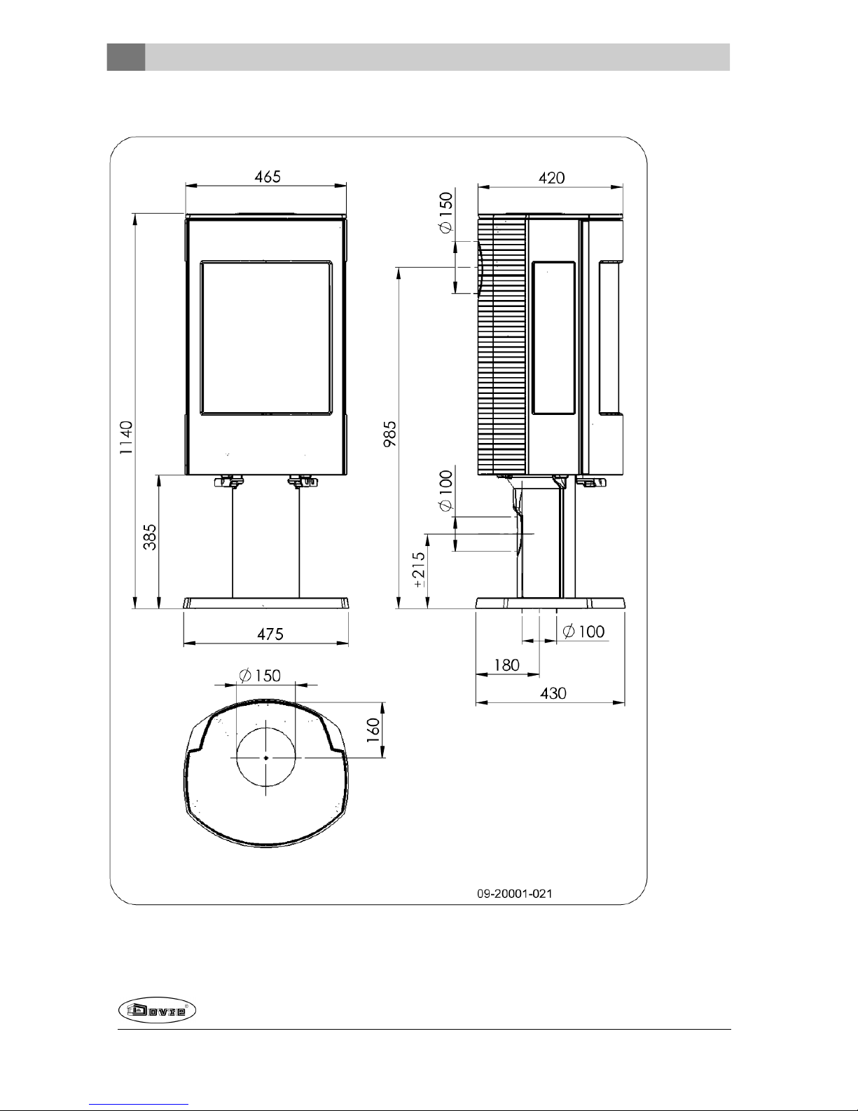
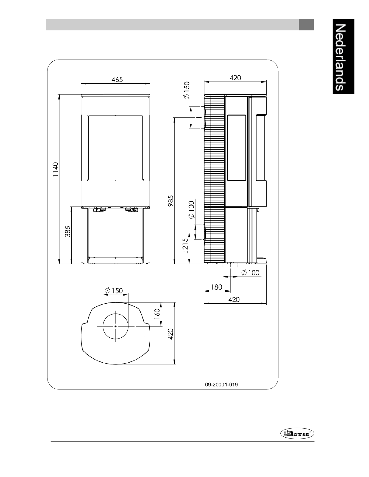
Bijlage 2: Afmetingen
ASTRO 3MFP
20
Wijzigingen op grond van technische verbeteringen voorbehouden
Page 21

Wijzigingen op grond van technische verbeteringen voorbehouden
21
ASTRO 3MFWB
Page 22
ASTRO 4MFP
22
Wijzigingen op grond van technische verbeteringen voorbehouden
Page 23
Wijzigingen op grond van technische verbeteringen voorbehouden
23
ASTRO 4MFWB
Page 24
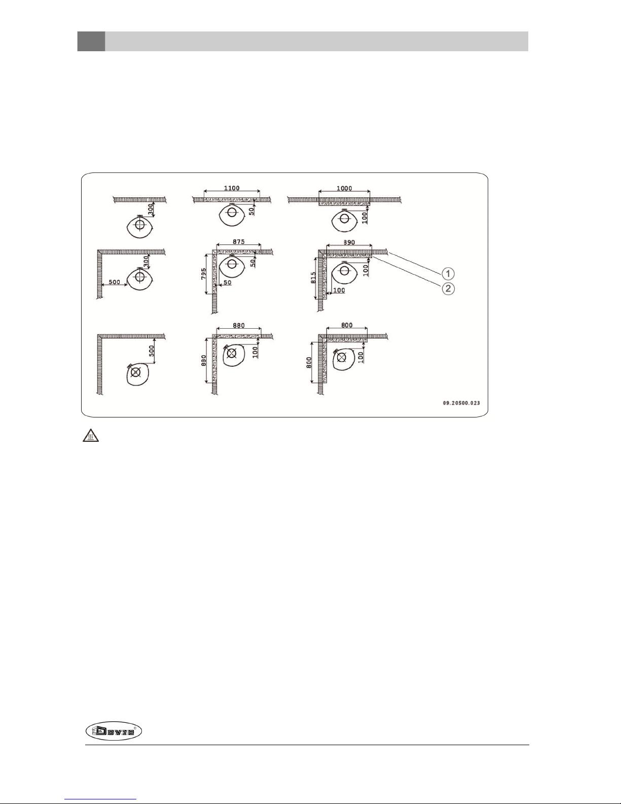
Bijlage 3: Afstand tot brandbaar materiaal
ASTRO 3
Minimale afstanden voor uitvoering zonder hitteschild:
Als de afstandvan deaansluitbuis minder dan 300mm verwijderd is van brandbaarmateriaal moet deze
worden afgeschermd.
1. Brandbaar materiaal
2. Onbrandbaar materiaal, dikte 100mm
24
Wijzigingen op grond van technische verbeteringen voorbehouden
Page 25
Wijzigingen op grond van technische verbeteringen voorbehouden
25
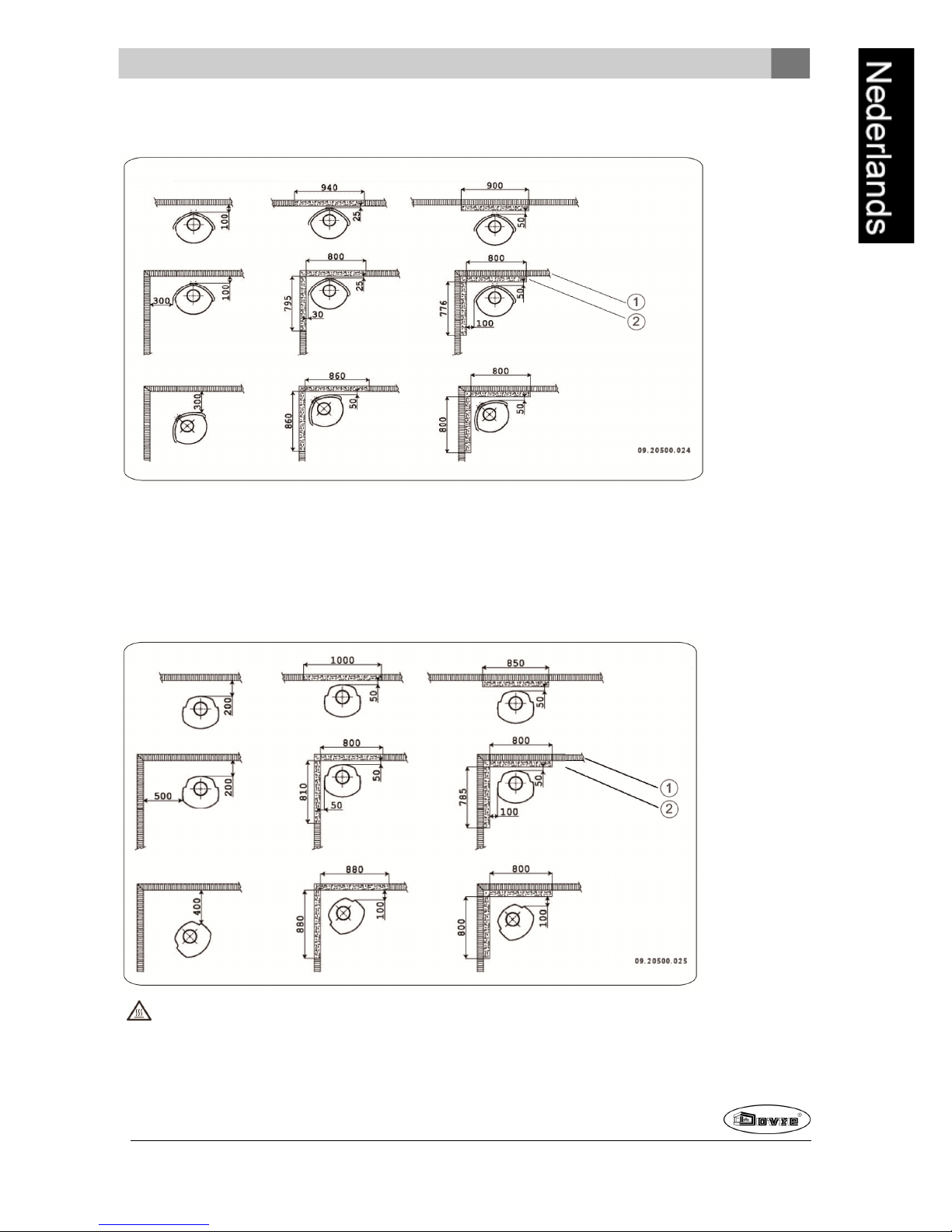
Minimale afstanden voor uitvoering met hitteschild:
1. Brandbaar materiaal
2. Onbrandbaar materiaal, dikte 100mm
ASTRO 4
Minimale afstanden voor uitvoering zonder hitteschild:
Als de afstandvan deaansluitbuis minder dan 300mm verwijderd is van brandbaarmateriaal moet deze
worden afgeschermd.
1. Brandbaar materiaal
2. Onbrandbaar materiaal, dikte 100mm
Page 26
Minimale afstanden voor uitvoering met hitteschild:
1. Brandbaar materiaal
2. Onbrandbaar materiaal, dikte 100mm
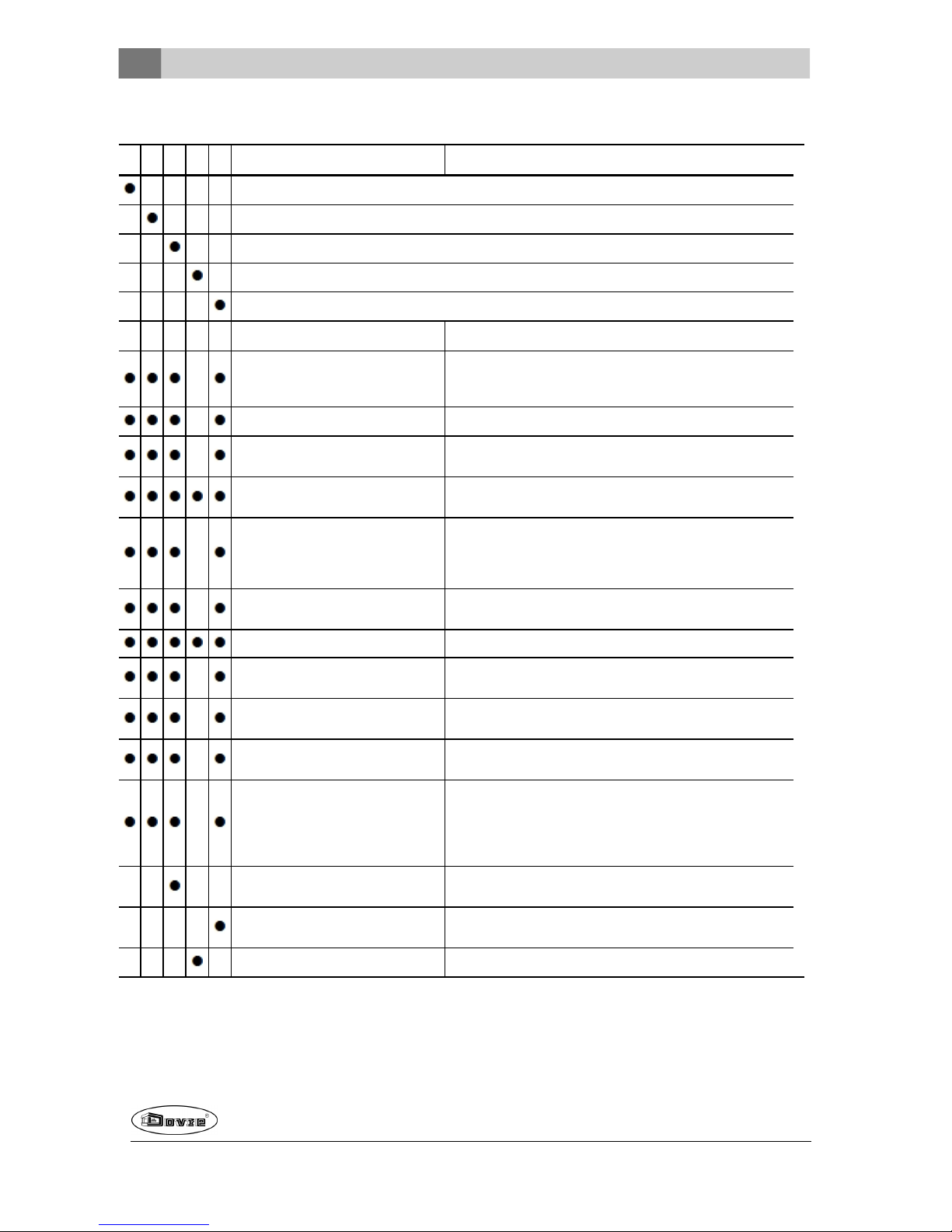
ASTRO 3 en ASTRO 4 - Afmetingen onbrandbare vloerplaat
A
B B
09-20002-004
26
Wijzigingen op grond van technische verbeteringen voorbehouden
Page 27

Wijzigingen op grond van technische verbeteringen voorbehouden
27
Minimale afmetingen onbrandbare vloerplaat
A (mm) B (mm)
Din 18891 500 300
Duitsland 500 300
Finland 400 100
Noorwegen 300 100
Page 28
Bijlage 4: Diagnoseschema
Probleem
Hout wil niet doorbranden
Geeft onvoldoende warmte
Rookterugslag tijdens het bijvullen
Toestel brandt te hevig, niet goed regelbaar
Aanslag op het glas
mogelijke oorzaak mogelijke oplossing
Onvoldoende trek
Een koudeschoorsteen creëert vaakonvoldoende trek. Volg de
instructiesvoor het aanmaken in het hoofdstuk"Gebruik"; open een
raam.
Hout te vochtig Gebruik hout met maximaal20% vocht.
Afmetingen hout te groot
Gebruik kleine stukjes aanmaakhout. Gebruik gekloven houtblokken
met een omtrek vanmaximaal 30 cm.
Stapeling hout niet correct
Stapel het hout zodanig dat er voldoende lucht tussende
houtblokken kan stromen (losse stapeling, zie "Stokenmet hout").
Werking van de schoorsteen
onvoldoende
Controleer of de schoorsteen aan de voorwaarden voldoet:
minimaal4 meter hoog, juiste diameter, goed geïsoleerd, gladde
binnenzijde, niette veelbochten, geen obstructiesin de schoorsteen
(vogelnest, te veel roetafzetting), hermetisch dicht (geen kieren).
Uitmonding vande schoorsteen niet
correct
Voldoende hoog boven het dakvlak, geen obstructiesin de
nabijheid.
Instelling vande luchtinlaten niet correct Open de luchtinlatenvolledig.
Aansluiting van het toestelmet de
schoorsteen niet correct
Aansluiting moet hermetischdicht zijn.
Onderdruk in de ruimte waar het toestel
isgeplaatst
Zet afzuigsystemen uit.
Onvoldoende toevoer van verselucht
Zorg voor voldoende luchttoevoer, maak desnoods gebruik van de
buitenluchtaansluiting.
Ongunstigeweersomstandigheden? Inversie (omgekeerde
luchtstroom in de schoorsteen door
hoge buitentemperatuur), extreme
windsnelheden
Bijinversieis gebruik van het toestelaf te raden. Plaatsdesnoods
een trekkende kap op de schoorsteen.
Tocht inde woonkamer
Voorkom tocht in de woonkamer; plaats het toestel niet in de
nabijheidvan een deur of verwarmingsluchtkanalen.
Vlammen raken het glas
Zorg dat het hout niet te dicht tegen het glasligt. Schuif de primaire
luchtinlaat verder dicht.
Toestel lekt lucht Controleer de afdichtingen vande deur en de naden van het toestel.
28
Wijzigingen op grond van technische verbeteringen voorbehouden
Page 29

Wijzigingen op grond van technische verbeteringen voorbehouden
29
Index
A
Aanmaakhout 28
Aanmaakvuur 12
Aansluiten
afmetingen 20
Aansluitenop buitenluchtaanvoer 9
Aansluitenop schoorsteen 8
aanbovenzijde 8
Aansluitkraag schoorsteenaansluiting 8
Aansluitset buitenluchtaanvoer 9
Aansteken 12
Afdichtingskoord van deur 16
Afmetingen 20
Antracietkolen 11
As verwijderen 14
bruinkool 13
Aslade
openen 15
verwijderen 7
B
Beluchtingvan het vuur 14
Bijvullen van brandstof 14
rookterugslag 28
Binnenplaten
gietijzeren 7
vermiculite 7
Binnenplaten, vuurvaste
verwijderen 7
Brandbaar materiaal
afstand tot 24
Brandstof
antracietkolen 11
benodigde hoeveelheid 15
bijvullen 13-14
bruinkool 11
bruinkoolbriketten 11
geschikte 11
hout 11
ongeschikte 11
Brandveiligheid
afstand tot brandbaar materiaal 24
meubels 6
vloer 6
wanden 6
Bruinkool
as 13
stoken 13
Bruinkoolbriketten 11
Buitenlucht
aansluitset monteren 9
Buitenluchtaanvoer 5, 9
aansluiting op 11
C
Creosoot 14
D
Demontabele onderdelen 7
Deur
afdichtingskoord 16
openen 7
Draagvermogenvan vloer 6
Drogen van hout 11
G
Geschikte brandstof 11
Gewicht 18-19
Gietijzer
binnenplaten 7
vuurvast 7
Gietijzeren binnenplaten 7
Glas
aanslag 28
schoonmaken 16
H
Hout 11
bewaren 11
drogen 11
geschikte soort 11
nat 11
wil niet doorbranden 28
Houtblokken stapelen 12
K
Kachelruitenreiniger 16
Kap op de schoorsteen 5
Kieren in toestel 16
Kolen
asgehalte 11
L
Lak 11
Page 30

Luchtinlaten 12
Luchtlek 16
Luchtregeling 13
Luchttoevoer regelen 14
M
Mist, niet stoken 15
Monteren
aansluitset buitenluchtaanvoer 9
Muren
brandveiligheid 6
N
Naaldhout 11
Nat hout 11
Nevel, niet stoken 15
Nominaal vermogen 15, 18-19
O
Onderdelen, demontabele 7
Onderhoud
afdichting 16
glas schoonmaken 16
schoorsteen 15
smeren 16
toestel schoonmaken 15
vuurvaste binnenplaten 16
Ongeschikte brandstof 11
Ontassen 14
Openen
aslade 15
deur 7
Opslagvan hout 11
P
Plaatsen
afmetingen 20
Primaire luchtinlaat 12
Problemenoplossen 15, 28
R
Rendement 18-19
Rook
bij eerste gebruik 11
Rookgas
massedebiet 18-19
temperatuur 18-19
Rookterugslag 4, 28
Ruiten
aanslag 28
schoonmaken 16
S
Schade 7
Schoonmaken
glas 16
toestel 15
Schoorsteen
aansluitdiameter 18-19
aansluiting op 11
aansluiting voorbereiden 8
hoogte 5
onderhoud 15
voorwaarden 5
Schoorsteenaansluiting
bovenzijde 8
Schoorsteenbrand voorkomen 14
Schoorsteenkap 5
Secundaireluchtinlaat 12
Smeren 16
Sokkel
afdekplaat 10
Stof-emissie 18-19
Stoken 12
antracietkolen 13
brandstof bijvullen 12-14
bruinkoolbriketten 13
onvoldoende warmte 15, 28
toestel brandt te hevig 28
toestel niet goed regelbaar 28
Stookregime 18-19
T
Teer 14
Temperatuur 18-19
Trek 18-19
U
Uitgaan van vuur 14
V
Vegen van schoorsteen 15
Ventilatie 5
buitenluchtaanvoeraansluiten 9
vuistregel 5
Ventilatierooster 5
30
Wijzigingen op grond van technische verbeteringen voorbehouden
Page 31

Wijzigingen op grond van technische verbeteringen voorbehouden
31
Verbrandingsluchtregeling 13
Vermiculite
vuurvast 7
Vermiculite binnenplaten 7
Verwijderen
as 14
aslade 7
vuurvaste binnenplaten 7
Vet voor smering 16
Vloeren
brandveiligheid 6
draagvermogen 6
Vloerkleed 6
Vulhoogte van toestel 13
Vuur
aanmaken 12
doven 14
Vuurvaste binnenplaten
onderhoud 16
verwijderen 7
waarschuwing 11
W
Waarschuwing
brandbare materialen 4
glas gebroken of gebarsten 4, 16
heet oppervlak 4
kachelruitreiniger 16
schoorsteenbrand 4, 11, 14
ventilatie 4-5
verzekeringsvoorwaarden 4
voorschriften 4
vuurvaste binnenplaten 11
Wanden
brandveiligheid 6
Warmte, onvoldoende 15, 28
Weersomstandigheden, niet stoken 15
Page 32

Table of contents
Introduction 3
Declaration of conformity 3
Safety 4
Installation requirements 4
General 4
Chimney (flue) 4
Ventilationof the area 5
Floors and walls 6
Product description 6
Installation 6
General preparation 6
Preparing the connection to the flue 8
Preparing the outside air connection 9
Installing and connecting 11
Use 11
First use 11
Fuel 11
Lighting 12
Burning wood 12
Burning brown coal briquettes 13
Burning anthracite coal 13
Controlling combustion air 14
Extinguishingthe fire 15
Removing ashes 15
Fog and mist 15
problems 16
Maintenance 16
Chimney 16
Cleaning andother regular maintenance activ-
ities 16
Appendix 1: Technical Data 18
Appendix 2: Measurements 20
Appendix 3: Distance from combustible
material 24
Appendix 4: Diagnostic diagram 28
Index 29
2
Subjectto change because of technicalimprovements
Page 33

Introduction
Dear user,
In buying this DOVRE heating appliance, you have
chosen a high quality product. This product is part of a
new generation of energy-efficient and
environmentally-friendly heating appliances. These
appliances make optimum use of convection heat as
well as thermal radiation (radiant heat).
Your DOVRE appliance has been manufactured
with state-of-the-art production equipment. In the
unlikely event of a malfunction, you can always
rely on DOVRE for support and service.
The appliance shouldnot be modified; please
always use original parts.
The appliance is intendedfor use in a living room. It
shouldbe connected hermetically to a wellfunctioning chimney.
We advise you have the appliance installed by an
authorized and competent installer.
DOVRE cannot be held liable for any problems or
damage resulting from incorrect installation.
Observe the following safety regulations when
installing and using the appliance.
In this manual, you can read how the DOVRE heating
appliance can be installed, used andmaintained
safely. Should you require additional informationor
technical data, or should you experience an
installation problem, please first contact your supplier.
© 2013 DOVRE NV
Declaration of
conformity
Notified body: 1625
The undersigned
Dovre nv, Nijverheidsstraat 18 B-2381 Weelde hereby
declares
that houtkachel Astro 3MFP, Astro 3MFWB, Astro
4MFP en Astro 4MFWB have been produced in
accordance with EN 13240.
Weelde01-03-2013
Due to continuous product improvement, the supplied
appliance specifications may vary from the
description in this brochure without prior notice.
DOVRE N.V.
Nijverheidsstraat 18 Tel: +32 (0) 14 65 91 91
B-2381 Weelde Fax: +32 (0) 14 65 90 09
Belgium E-mail : info@dovre.be
Subjectto change because of technicalimprovements
3
Page 34

Safety
Please note: All safety regulations must be
compliedwith strictly.
Please read carefully the instructions supplied
with the appliance for installation, use and
maintenance, before using the appliance.
The appliance must be installed in accordance
with the laws and requirements of your
country.
All local regulations andthe regulations relating
to national and European standards must be
observed when installing the appliance.
The appliance shouldpreferably be installedby
an authorized installer. Installers will be aware
of the applicable regulations and requirements.
The appliance is designedfor heating
purposes. All surfaces, including the glass and
connecting tube, can get very hot (over 100°C)!
For operation, use a so-called "cold hand" or an
oven glove. Make sure there is sufficient
protection if young children, disabled persons
or oldpeopleare in the vicinity of the appliance.
Safety distances from flammable materials
must be adhered to strictly.
Don't place any curtains, clothes, laundry or
othercombustible materials on or near the
appliance.
Don't use flammable or explosive substances
near the appliance when it is in use.
Avoid a chimney fire by having the chimney
swept regularly. Never burn wood with the door
open.
In the case of a chimney fire: close all air inlets
of the appliance and alert the fire brigade.
If the glass in the appliance is broken or
cracked, it must be replaced before you can
use the appliance again.
Make sure there is adequate ventilationin the
room where the appliance is installed. If
ventilation is insufficient, combustion will be
incomplete resultingin toxic gases being
produced and spread through the room. See
the chapter "Installation requirements" for more
information onventilation.
Installation
requirements
General
The appliance must be connected tightly to a wellfunctioning chimney.
For the connection measurements: see the
appendix "Technical data".
Ask the fire brigade and/or yourinsurance
company about any specific requirements and
regulations.
Chimney (flue)
The flue or chimney is needed for:
Removal of combustion gases via natural draught.
As the warm airin the flue orchimney is lighter
than the outside air, it rises.
Air intake, needed for the combustion of fuel in the
appliance.
A poorly-functioning flue or chimney can cause smoke
to escape into the room when the door is opened.
Damage caused by smoke emissions into the room is
not covered by the warranty.
Do not connect multiple appliances (such as a
boiler for central heating) to the same flue,
unless local ornational regulations allow this.
In the event of two connections ensurethat the
difference in height between the connections is
no less than 200 mm.
Ask your installer for advice regarding the flue. Refer
to the European norm EN13384for a correct
calculations for the flue.
4
Subjectto change because of technicalimprovements
Page 35

The flue must satisfy the followingrequirements:
The flue or chimney must be made of fire-resistant
material, preferably ceramics orstainless steel.
The flue or chimney must be airtight andwellcleaned andguaranteesufficient draught.
A draught/vacuum of 15-20Paduringnormal
operation is ideal.
Starting from the flue spigot, the flue must run as
vertically as possible. Changes in direction and
horizontal pieces disrupt the outwardflow of
combustion gases and may cause soot deposits.
To prevent combustion gases from coolingdown
too much, which reduces the draught, ensure that
the interior diameter is not too big.
The flue or chimney should ideally have the same
diameter as the connection collar.
For the nominal diameter: see the appendix
"Technical data". If the smoke channel is well
insulated, the diameter may be slightly bigger
(upto 2x the section of the connection collar).
The section (area) of the smoke channel must be
constant. Wider segments and (in particular)
narrower segments disrupt the outwardflow of
combustion gases.
When usinga cover plate or exhaust hood : make
sure that the cover does not restrict the flue outlet
andthat the cap does not impede the outward flow
of combustion gases.
The flue must end in a zone that is not affected by
surrounding buildings, trees or otherobstacles.
The flue outside the house must be insulated.
The chimney must be at least 4metres high.
As a rule of thumb: 60cm above the ridge of the
roof.
If the ridge of the roof is more than 3metres away
from the flue: stick to the measurements in the
following figure. A = the highest point of the roof
within a distance of 3metres.
Ventilation of the area
For good combustion, the stove needs air (oxygen).
This air is supplied via adjustable air inlets from the
area in which the stove is installed.
The combustion will be incomplete in case of
insufficient ventilation, which results in toxic
gases being produced andspread throughthe
area.
As a rule of thumb, the air supply should be 5,
5cm²/kW. Extra ventilation is needed when:
The stove is in an areathat is well-insulated.
There is mechanical ventilation, for example a
central extraction system or an extraction hoodin
an open kitchen.
You can provide extra ventilationby having a
ventilation louvre fitted on the outside wall.
Make sure that otherair consumingappliances (such
as tumble-driers, other heating appliances or a
bathroom fan) have their own supply of outside air, or
areswitchedoff when you use the appliance.
You can also connect the appliance to an
outside airsupply. This makes additional
ventilation unnecessary.
Subjectto change because of technicalimprovements
5
Page 36

Floors and walls
The floor on which the appliance is placed must have
sufficient bearing capacity. For the weight of the
appliance, see the appendix "Technical data".
Protect flammableflooring from heat radiation
by means of a fireproof protective plate. See
the appendix "Distance from combustible
material".
Remove combustible material such as
linoleum, carpets/rugs and similar materials
below the fireproof protective plate.
Keep sufficient distance between the
appliance and combustible materials such as
wooden walls and furniture.
The connecting tubealso radiates heat. Ensure
that there is sufficient distance or a shield
between the connecting tube and combustible
material.
The rule of thumb for a single-walled tube is a
distance of 3x the diameter. If a lining shell is
fitted around the tube, a distance of 1x the
diameter is permissible.
Carpets and rugs must be at least 80cm away
from the fire.
Use a fireproof floor plate to protect a
flammable floor from any ash which may fall in
front of the stove. The protective plate must
comply with national standards.
For the dimensions of the fireproof protective
plate: see the appendix "Distance from
combustible material".
For further requirements in connection with fire
safety: see the appendix "Distance from
combustible material".
Product description
1. Fire grate
2. Door
3. Primary air slide
4. Door latch
5. Secondary air slide
6. Riddling rod
Installation
General preparation
Please check the appliance immediately after
delivery for damage caused duringtransport or any
otherdamage or defects. The appliance is attached
to the pallet with screws at the bottom.
6
Subjectto change because of technicalimprovements
Page 37

If you detect damagecaused during transport
or any other damageor defects, do not use the
appliance and notify the supplier.
Remove the removable parts (fire-resistant inner
plates, fire grate, top plate, ash pan) from the
appliance before you start installing the appliance.
It is easier to move the appliance and to avoid
damage if the removable parts have been
removed.
Note the location of the removableparts, so
that you can re-position the parts in the correct
place lateron.
1. Open the door; see the followingfigure.
2. Remove the fire-resistant inner plates; see the
following figure.
Vermiculite inner plates are light and tend to be
ochrous in colour on delivery. They insulate the
combustion chamber to boost combustion.
Cast iron inner plates protect the combustion
chamber and dissipate heat to the
surroundings.
1
2
7
4
7
5
3
6
09.20019.033
Removable internal sections
astro3 series
1 03.77099.002 Fire basket front
2 03.77400.002 Fire basket left
3 03.77401.002 Fire basket right
4 03.08365.002 Inner plate
5 03.61115.100 Grate
6 03.66532.100 Fire grate
astro4 series
1 03.77099.002 Fire basket front
2 03.77402.002 Fire basket left
3 03.77403.002 Fire basket right
4 03.08365.002 Inner plate
5 03.61115.100 Grate
6 03.66532.100 Fire grate
7 03.35210.000 Corner piece
4. Remove the ash pan; see the following figure.
Subjectto change because of technicalimprovements
7
Page 38

Preparing the connection to
the flue
When connecting the stove to the flue, you can
choose to connect to the top orrear of the stove.
When the appliance is delivered, the
connection on the rear is left open.
Plug the outlet you don't wish to use with the
correspondingsupplied cover.
Install the supplied corresponding connection collar
to the outlet you wish to use.
Sealant and materials aresupplied.
1 Connection - top
2 Connection - rear
Connect to top
1. Remove the top plate.
The top plate can be taken off the appliance
just like that.
2. At the outlet at the top, apply sealant to the
contact surface where the connection collar will be
positioned.
3. Install the connection collar with the materials.
4. At the outlet at the rear, apply sealant to the
contact surface where the cover will be
positioned.
5. Install the cover using the materials.
8
Subjectto change because of technicalimprovements
Page 39

Connecting to the rear
1. Remove the top plate.
The top plate can be taken off the appliance
just like that.
2. At the outlet at the top, apply sealant to the
contact surface where the cover will be
positioned.
3. Install the cover using the materials.
4. At the rear, apply sealant to the contact surface
wherethe connection collarwill be positioned.
5. Install the connection collar with the materials.
Preparing the outside air
connection
If the appliance is installedin a room without sufficient
ventilation, you can install a connecting kit on the
appliance for the outside air supply. Some of the air
inlets on the appliance must thenbe plugged with the
blanking material provided. We recommend applying a
connection set that has a valve you can close when
the stove is not in use.
The airsupply tube is 100 mm in diameter. If the tube
is smooth, it may be no longer than 12 metres. If
accessories such as bends are used, the maximum
length (12 m) must be reduced by 1 m for each
accessory used.
1. Close the air inlet in the bottom plate with the
small cast-iron cover plates (1) and screws (2);
see following figure.
By closing the air inlet in the bottom plate you
prevent air being usedfor combustion from an
insufficiently ventilatedspace.
2. For connection to outside air via the floor:
a. Make an opening in the floor; see 'Appendix 2,
Measurements' for the correct position of the
opening.
b. Slide a straight air supply tube onto the
connection collar of the stove, so that it cannot
move; see following figure .
Subjectto change because of technicalimprovements
9
Page 40

3. For connection to outside air via the rear of the
appliance:
a. Create an opening in the base orthe log
compartment by removing the panel at the
back of the base or the logcompartment; see
following figures.
Dependingon the version of the stove the
cover plate is affixed either with springy
clips or with a washer plate. In case of a
springfixing use a screwdriverto lift the
cover plate out of its groove.
b. Connect a so-called 'elbow' hermetically to the
openingin the base or the log compartment so
that it cannot move; see following figure.
The height for the connection through the
wall may vary depending on the elbow
type.
10
Subjectto change because of technicalimprovements
Page 41

EN 1856-2
DIN 1298
Ø100 - 90°
09-20001-017
Installing and connecting
1. Position the stove in the correct place, and make
sure it is level.
2. Connect the appliance airtight to the flue
(chimney).
3. In the case of connection to outside air: connect
the outside air supply to the connection collar
within the base or log compartment of the stove or
to the fitted elbow.
4. Re-position all removed parts in the correct places
in the stove.
Never light a fire in the appliance without the
fireproof inner plates.
The appliance is now ready for use.
Use
First use
When you use the stove for the first time, make an
intense fire and keep it goingfor a good few hours.
This will cure the heat-resistant paint finish. This may
result in some smoke andodours. You could open
windows and doors for a while in the area in which the
stove is located.
Fuel
The appliance is suitable for the burning of natural
wood; sawn and choppedwood that is sufficiently dry.
The appliance is also suitable for the burning of brown
coal briquettes andanthracite coal.
Do not use other fuels, as they can cause serious
damage to the stove.
You are not allowedto use the following fuels, as they
pollute the environment and because they heavily soil
the appliance and flue, which may leadto a chimney
fire:
Treated wood, such as scrap wood, painted wood,
impregnated wood, preserved wood, plywood and
chipboard.
Plastics, scrap paperand domestic waste.
Wood
Hardwood, such as oak, beech, birch andfruit tree
wood is the ideal fuel for your stove. This type of
wood burns slowly with calm flames. Softwood
contains more resins, burns faster and sparks
more.
Use seasoned wood that contains no more than
20% moisture. The wood should have been
seasoned for at least 2 years.
Saw the wood to size andsplit it while it is still
fresh. Fresh wood is easier to split, andsplit wood
dries more easily. Store the woodundera roof
wherethe wind has free access.
Do not use damp wood. Damp logs do not produce
heat as all the energy is used in the evaporation of
moisture. This will result in a lot of smoke andsoot
deposits on the stove door and in the chimney. The
water vapour will condense in the stove and can
leak away through chinks in the stove, causing
black stains on the floor. It may also condense in
the chimney and form creosote. Creosote is a
highly flammable compoundand may cause a
chimney fire.
Brown coal briquettes
Brown coal briquettes have approximately the same
burningcharacteristics as wood.
Ensurethere is a good charcoal bed before you
start burning brown coal briquettes.
For lighting the fireplace, follow the instructions in
the "Lighting" paragraph.
Subjectto change because of technicalimprovements
11
Page 42

Anthracite coal
Anthracite coal is categorised onthe basis of
properties, sometimes prescribed by law, such as the
percentage of volatile substances. The ash content of
anthracite coal is between 3% and13%. The lower the
ash content, the higherthe net heatingvalueand the
less often you have to remove ash.
Preferably use category A anthracite coal with a
low ash content.
Use the recommended size 12/22 or 20/30.
For lighting the fireplace, follow the instructions in
the "Lighting" paragraph.
Lighting
You can check whether the flue has sufficient draught
by lighting a ball of paper above the baffle plate. A cold
flue often has insufficient draught and consequently,
some smoke may escape into the room insteadof up
the chimney. You can avoid this problem by lighting
the fire as described below.
1. Stack two layers of medium sized logs crosswise.
2. Stack two layers of kindling crosswise on top of
the logs.
3. Place a firelighter cubein the lowerlayer of
kindlingand light the cube according to the
instructions on the packaging.
4. Close the door of the appliance and open the
primary air inlet and open the secondary air inlet of
the appliance; see 'Controlling air combustion'.
5. Allow the fire develop into a good blaze until there
is glowing bedof charcoal. You can then add fuel
andadjust the appliance, see the chapter"Stoking
with wood".
Burning wood
After you have followed the instructions for lighting :
1. Slowly openthe stove door.
2. Spreadthe charcoal evenly across the bottom of
the stove base.
3. Stack a few logs on the charcoal.
Open stacking
If the logs are stacked openly, the wood will burn
quickly as the oxygen can reach each log easily. If
you want to use the stove for a short while, make an
open stack.
12
Subjectto change because of technicalimprovements
Page 43

Compact stacking
If the logs are stacked tightly, the wood will burn more
slowly as the oxygen can only reach some logs
easily. If you want to burn woodfor a longer period,
make a compact stack.
4. Close the door of the appliance.
5. Close the primary air inlet and leave the secondary
air inlet open.
Fill the appliance up to one third capacity.
Burning brown coal
briquettes
Brown coal briquettes burn in almost the same way as
wood. Using the primary air inlet, ensure sufficient
supply of air under the fire. For further information see
the paragraph "Burning wood".
Burning brown coal briquettes creates a lot of ash.
Regularly remove excess ash. See the paragraph
"Removing ashes" for instructions.
For the properties and use of brown coal
briquettes: consult your brown coal briquettes
supplier or see the brown coal briquettes'
packaging.
After you have followed the instructions for lighting:
1. Slowly openthe stove door.
2. Spreadthe charcoal evenly across the bottom of
the stove base.
3. Place the brown coal briquettes on the charcoal
bed.
4. Close the door.
5. Regularly remove ashes from the stove base
riddling the grate. Use the cold handle to operate
the riddling rod.
Burning anthracite coal
Always close the secondary air slide when
burninganthracite coal.
Set the fuel choice air valve to the closed
position.
After you have followed the instructions for lighting:
1. Open the primary air slide completely.
2. Slowly openthe stove door.
3. Spreadthe charcoal evenly across the bottom of
the stove base.
4. Spreada shovelful of coal on the charcoal bedand
wait with the next shovelful until the coals start to
glow.
5. Now add more coal.
Be careful not to smotherthe fire by adding too
much coal at once.
You have added as much as you can once the
glow of the previous load is only just visible.
6. Close the door.
7. Allow the coals to burn well for a few minutes and
control the air supply using the primary air slider.
If the fire basket or the cast-iron plates start to
glow redyou have overfedthe fire.
8. Regularly remove ashes from the stove base
riddling the grate. Use the cold handle to operate
the riddling rod.
Subjectto change because of technicalimprovements
13
Page 44

Controlling combustion air
The appliance has various features for air control; see
following figure.
1.
The primary air slide is open in pulled out
position and closed in pushed back position.
2.
The secondary air slide is open in pulled out
position and closed in pushed back position.
The primary air slide controls the air flow under the
grille (1);see following figure.
The secondary air slide controls the air flow for the
glass and the vents in the back wall (2).
Advice
Never burn wood with an open door.
Regularly burn wood with intense roaring fires.
If you frequently have low intensity fires, tar
andcreosote may be deposited in the chimney
. Tar and creosote are highly combustible
substances. Thicker layers of these
14
Subjectto change because of technicalimprovements
Page 45

substances may catch fire if the temperaturein
the chimney increases suddenly. By allowing
the fire to burn very intensely regularly, layers
of tar and creosote will disappear.
Low intensity fires also cause tar deposits on
the stove window and door.
When the outside temperature is not very low,
it is better to burn wood intensely for a few
hours instead of havinga low intensity fire for a
longperiodof time.
Control the air supply with the secondary air inlet.
The secondary air inlet not only supplies air to
the fire but to the glass as well, so that it does
not quickly become dirty.
Open the primary air inlet for the time being if the air
supply by the secondary air inlet is inadequate or if
you want to fan the fire.
It is better to add a small amount of logs regularly
than to add many logs at the same time.
Extinguishing the fire
Do not add fuel and just let the fire goout. If a fire is
damped down by reducingthe air supply, harmful
substances will be released. For this reason, the fire
shouldbe allowed to go out naturally. Keep aneye on
the fire until it has gone out. All air inlets can be closed
once the fire has died completely.
Removing ashes
After the wood has been burnt, a relatively small
amount of ashes is left over. This bed of ashes is a
good insulating layer for the stove base plate and
improves combustion. It is good to leave a thin layer
of ashes on the stove base plate.
The flow of air through the fire plate must not be
obstructed, however, andno ash may be allowed to
accumulate behind a cast-iron inner plate. Remove
the excess ash regularly.
After the brown coal briquettes and anthracite coal
has been burnt, a relatively large amount of ash is left
over. No ash may be allowedto accumulate
underneath the fire grate and the ash should never
reach the bottom of the grate. This will cause the grate
to overheat andbe damaged.
1. Use the riddling rodto freethe grate of excess
ashes.
If the appliance is still warm, use the "cold
hand" to operate the riddling rod.
2. Open the stove door.
3. Using the scraper, sweep the remaining ashes
through the grid.
4. Remove the ashtray (see next figure)using the
glove provided and empty the ashtray.
5. Replace the ash pan and close the stove door.
Fog and mist
Fog and mist hinderthe flow of flue gases through the
flue. Smoke can blow back and cause a stench. If it is
not strictly necessary, it is better not to use the stove
in foggy andmisty weather.
Subjectto change because of technicalimprovements
15
Page 46

problems
Refer to the appendix "Diagnostic diagram" to resolve
any problems in using the stove.
To reach the nominal output, approximately 2
kg of fuel needs to be burnt every 45 minutes.
Maintenance
Follow the maintenance instructions in this chapter to
keep the stove in good condition.
Chimney
In many countries, you are required by law to have
your chimney checked and maintained.
At the beginning of the heating season: have the
chimney swept by an expert.
Duringthe heating season and after the chimney
has not been usedfor a long time: have the
chimney checked for soot deposits.
After the heating season: seal off the chimney with
a ball of paper.
Cleaning and other regular
maintenance activities
Do not clean the stove when it is still warm.
Clean the exterior of the stove with a dry lint-free
cloth.
You can cleanthe stove interior thoroughly at the end
of the heating season:
If necessary, first remove the fire-resistant inner
plates. See the chapter "Installation" for
instructions on removing and installing the inner
plates.
If necessary, clean the air supply ducts. Remove
the top plate to this end. The top plate lies loosely
on the appliance.
If required, remove the baffle plate at the top of the
appliance and clean it.
Remove and install baffle plate
Unscrew the clamping plate on the front of the baffle
plate. Lift the baffle plate from the support and tilt the
baffle plate out of the appliance. Please ensure that
the rear of the baffle plate properly connects to the air
tunnel at the back of the appliance when reinstalling.
1
09.20019.034
Checking fire-resistant inner plates
The fire-resistant inner plates are consumables and
subject to wear . Vermiculite innerplates are fragile.
Do not knock the inner plates with logs. Check the
fire-resistant innerplates frequently and replace them
when necessary.
See the chapter "Installation" for instructions on
removing and installing the inner plates.
The insulating vermiculite orchamotte inner
plates may develop hairline cracks, but this
does not affect their performance adversely.
Cast-iron inner plates last a longtime if you
remove frequently the ash that can accumulate
behind them. If accumulated ash behindthe
cast-iron plate is not removed, the plate will no
longer beable to dissipate the heat to the
surroundings and this may cause the plate to
warp orcrack.
Never use the stove without the fire-resistant
inner plates.
Cleaning glass
Dirt clings less easily to well-cleaned glass. Proceed
as follows:
16
Subjectto change because of technicalimprovements
Page 47

1. Remove dust and loose soot with a dry cloth.
2. Clean the glass with stove glass cleaner:
a. Apply stove glass cleaner to a kitchen sponge,
rubdown the entireglass surface and give the
cleaning agent time to react.
b. Remove the dirt with a moist cloth or kitchen
tissue.
3. Clean the glass again with a normal glass cleaning
product.
4. Rub the glass cleanwith a dry cloth or kitchen
tissue.
Do not use abrasive or aggressive products to
clean the glass.
Wear household gloves to protect your hands.
If the glass in the appliance is broken or
cracked, it must be replaced before you can
use the appliance again.
Make sure that no stove window cleaner runs
between the glass and the cast-iron door.
Lubrication
Although cast-iron is slightly self-lubricating, you will
still need to lubricate moving parts frequently.
Lubricate the movingparts (such as guide
systems,hingepins, latches and air slides) with
heat resistant grease that is available in the
specialist trade.
Touching-up the paint finish
Small areas of damaged paint finish can be touchedup with a spray can of special heat-resistant paint,
available from yoursupplier.
Areas of damaged enamel can betouched up with a
special heat-resistant paint finish that is available
from your supplier.
Checking the seal
Check whether the door sealing rope is still in good
conditionand works well. The sealing rope is
subject to wear andwill need to be replacedover
time.
Check the appliance for air leaks. Close any
chinks with stove sealant.
Allow the sealant to harden fully beforelighting
the stove, as any moisturein the sealant will
form bubbles, resulting in a new air leak.
Subjectto change because of technicalimprovements
17
Page 48

Appendix 1: Technical Data
Model
Astro 3MF
Astro 4MF
Fire regime Non continuous use
Nominal output 8 kW
Chimney connection (diameter) 150 mm
Weight +/- 140 kg
Recommendedfuel Wood
Brown coal
briquettes
Anthracite
coal
Fuel property max. 33 cm 3" - 6" - 7"
12/22
20/30
Mass flow of flue gases 7.4 g/s 6.1 g/s 7.3 g/s
Flue gas temperature in measurement section
297℃ 252 ℃ 261 ℃
Temperature at the appliance outlet 351 ℃ 454 ℃ 321 ℃
Minimum draught 12 Pa 12 Pa 12 Pa
CO emission (13%O2) 0,09 % 0,04 % 0,10 %
NOx emission (13%O2) 123 mg/Nm³ 151mg/Nm³ 123mg/Nm³
CnHm emission (13%O2) 71 mg/Nm³ 28 mg/Nm³ 90 mg/Nm³
Particulate emission 18 mg/Nm³ 17 mg/Nm³ 15 mg/Nm³
Efficiency 76,7 % 82,8 % 80,0 %
18
Subjectto change because of technicalimprovements
Page 49

Model
Astro 3MF
Astro 4MF
Fire regime Continuous use
Nominal output 8 kW
Chimney connection (diameter) 150 mm
Weight +/- 140 kg
Recommendedfuel Brown coal briquettes Anthracite coal
Fuel property 3" - 6" - 7"
12/22
20/30
Mass flow of flue gases 7 g/s 8.6 g/s
Flue gas temperature in the measurement section 252℃ 247 ℃
Temperature at the appliance outlet 440 ℃ 301 ℃
Minimum draught 12 Pa 12 Pa
CO emission (13%O2) 0,13% 0,16 %
NOx emission (13%O2) 161 mg/Nm³ 116 mg/Nm³
CnHm emission (13%O2) 45 mg/Nm³ 85 mg/Nm³
Particulate emission 5 mg/Nm³
Efficiency 79,8 % 79,5 %
Subjectto change because of technicalimprovements
19
Page 50

Appendix 2: Measurements
ASTRO 3MFP
20
Subjectto change because of technicalimprovements
Page 51

ASTRO 3MFWB
Subjectto change because of technicalimprovements
21
Page 52

ASTRO 4MFP
22
Subjectto change because of technicalimprovements
Page 53

ASTRO 4MFWB
Subjectto change because of technicalimprovements
23
Page 54

Appendix 3: Distance from combustible material
ASTRO 3
Minimum distances for versions without heat shield:
If the distance between the connecting tube and combustible materials is less than 300 mm the connecting tube shouldbe protected.
1. Combustible material
2. Incombustible material, thickness 100mm
24
Subjectto change because of technicalimprovements
Page 55

Minimum distances for versions with heat shield:
1. Combustible material
2. Incombustible material, thickness 100mm
ASTRO 4
Minimum distances for versions without heat shield:
If the distance between the connecting tube and combustible materials is less than 300 mm the connecting tube shouldbe protected.
Subjectto change because of technicalimprovements
25
Page 56

1. Combustible material
2. Incombustible material, thickness 100mm
Minimum distances for versions with heat shield:
1. Combustible material
2. Incombustible material, thickness 100mm
ASTRO 3 and ASTRO 4 - Dimensions of fireproof floor plate
A
B B
09-20002-004
26
Subjectto change because of technicalimprovements
Page 57

Minimal dimensions of fireproof protective plate
A (mm) B (mm)
Din 18891 500 300
Germany 500 300
Finland 400 100
Norway 300 100
Subjectto change because of technicalimprovements
27
Page 58

Appendix 4: Diagnostic diagram
Problem
Wood will not stay lit
Gives off insufficient heat
Smoke emissions into the room when adding wood
Fire in stove is too intense, is hard to adjust
Deposit on the glass
Possible cause Possible solution
Insufficient draught
A cold flue usuallyfailsto create sufficient draught. Follow the
instructionsfor lightingin the "Use" chapter; open a window.
Wood too damp Use wood with no more than 20% moisture.
Logs too large
Use small pieces of kindling. Use split logs no larger than 30 cm in
circumference.
Wood stacked incorrectly
Stackthe logsin a way that allows adequate air flow between the
logs(open stacking, see "Burning wood")
Chimney does not work properly
Check whether the chimneymeets the requirements: at least 4
metres high, right diameter, wellinsulated, smooth inside,not too
many bends, no obstructions in chimney(bird's nest, too much soot
deposit), hermetically tight (no chinks).
Chimney stack incorrect Sufficiently high above the roof, no obstaclesin the vicinity
Air inlets setincorrectly Open the air inletscompletely.
Stove connected to the chimney
incorrectly
Connection should be hermeticallytight.
Vacuum in area in whichthe stoveis
installed
Switch off extraction systems.
Insufficient supplyof fresh air
Provide an adequate air supply; ifnecessary use outsideair
connection.
Adverse weather conditions?
Inversion (reversed air flow in chimney
because of a highoutside temperature),
extreme wind speeds
We recommend you don't use the appliance inthe caseof inversion.
If required, install an extra hood on the flue to increase the draught.
Draught in the living room
Avoiddraught inthe living room, do not place the appliance near a
door or heating air ducts.
Flames touchthe glass
Make sure the wood isnot positioned too closeto the glass. Slide the
primary air inlet cover closer to the "Closed" position.
Stove is leaking air Check the door seals and stove joints.
28
Subjectto change because of technicalimprovements
Page 59

Subjectto change because of technicalimprovements
29
Index
A
Adding fuel 15
Adding wood
smoke emissions into the room 28
Air control 14
Air inlets 12
Air leak 17
Air supply for fire 15
Anthracite coal 12
Ash pan
remove 7
Ashes
remove 15
Ashtray
open 15
B
Bearing capacity of floor
Floors
bearingcapacity 6
Brown coal
ash 13
burning 13
Brown coal briquettes 11
Burning
adding fuel 13
anthracite coal 13
brown coal briquettes 13
Burning wood 12
addfuel 15
adding logs 12
appliance is hard to adjust 28
fire is too intense 28
insufficient heat 16, 28
C
Carpet 6
Cast iron
fire resistant 7
inner plates 7
Cast iron inner plates 7
Chimney
connection diameter 18-19
connection to 11
height 5
prepare connection 8
sweep 16
Chinks in appliance 17
Clean
glass 16
Cleaning
appliance 16
Coal
ash content 12
Combustible material
distance from 24
Combustion air control 14
Connection
measurements 20
Connection collar for connection to chimney 8
Connection set for outside air supply 9
Connection to chimney 8
at top 8
top 8
Connection to outside air supply 9
Control air supply 15
Cover on flue 5
Creosote 14
D
Damage 7
Damp wood 11
Door
open 7
sealingrope 17
Draught 18-19
Drying wood 11
E
Efficiency 18-19
F
Filling height 13
Fire
extinguishing 15
lighting 12
Fire-resistant inner plates
maintenance 16
remove 7
Fire going out 15
Page 60

Fire regime 18-19
Fire safety
distance from combustible material 24
floor 6
furniture 6
walls 6
Fireproof innerplates
warning 11
Floors
fire safety 6
Flue
maintenance 16
requirements 5
Flue gas
mass flow 18-19
temperature 18-19
Fog, do not burn wood 15
Foot
cover plate 10
Fuel
adding 15
adding wood 13
anthracite coal 11-12
brown coal 11
brown coal briquettes 11
necessary amount 16
required amount 16
suitable 11
unsuitable 11
wood 11
G
Glass
clean 16
deposit 28
H
Heat, insufficient 16
Heat,insufficient 28
Hood onthe flue 5
I
Innerplates
cast iron 7
vermiculite 7
Innerplates, fire-resistant
remove 7
Install
connection set for outside air supply 9
Installation
measurements 20
K
Kindled fire 12
Kindling 28
L
Lighting 12
Lubricant 17
Lubricate 17
M
Maintenance
chimney 16
clean glass 16
cleaning the appliance 16
fire-resistant innerplates 16
lubrication 17
sealing 17
Measurements 20
Mist, do not burn wood 15
N
Nominal output 16, 18-19
O
Open
ashtray 15
door 7
Outside air
install connection set 9
Outside airintake
connection to 11
Outside airsupply 9
P
Paint finish 11
Particulate emission 18-19
Parts, removable 7
Prevent a chimney fire 14
Primary air inlet 12
R
Removable parts 7
30
Subjectto change because of technicalimprovements
Page 61

Subjectto change because of technicalimprovements
31
Removal of ashes 15
Remove
ash pan 7
fire-resistant innerplates 7
Remove ashes 15
Removing ash
brown coal 13
S
Screens
clean 16
deposit 28
Sealing rope for door 17
Secondary air inlet 12
Smoke
on first use 11
Smoke emissions into the room 4, 28
Softwood 11
Solving problems 16, 28
Stacking logs 12
Storingwood 11
Stove window cleaner 16
Suitable fuel 11
Supply of outside air 5
Sweep chimney 16
T
Tar 14
Temperature 18-19
U
Unsuitable fuel 11
V
Ventilation 5
connect outside air supply 9
ruleof thumb 5
Ventilationlouvre 5
Vermiculite
fire-resistant 7
Vermiculite inner plates 7
W
Walls
fire safety 6
Warning
chimney fire 4, 11, 14
combustible materials 4
fireproof inner plates 11
glass broken or cracked 4, 17
hot surface 4
regulations 4
stove window cleaner 17
terms and conditions for insurance 4
ventilation 4-5
Weatherconditions, do not burn wood 15
Weight 18-19
Wood 11
damp 11
does not keep burning 28
drying 11
right sort 11
storing 11
Page 62

Table des matières
Introduction 3
Déclaration de conformité 3
Sécurité 4
Conditions d'installation 5
Généralités 5
Ventilationde la pièce 5
Sols et murs 6
Description du produit 6
Installation 6
Préparation générale 6
Préparation du raccordement au conduit de
cheminée 8
Préparation du raccordement d'air extérieur 9
Pose et raccordement 11
Utilisation 11
Première utilisation 11
Combustible 11
La combustion au bois 12
La combustion avec des briquettes de lignite 13
Allumerun feu avec de l'anthracite 13
Extinction dufoyer 14
Décendrage 15
Brouillard et brume 15
Résolutionproblèmes 15
Entretien 15
Conduit de cheminée 15
Nettoyage et autreentretienrégulier 16
Annexe 1 : Caractéristiques techniques 18
Annexe 2 : Dimensions 20
Annexe 3 : Distance d'éloignement avec des
matériaux combustibles 24
Annexe 4 : Tableau de diagnostic 28
Index 29
2
Sous réserve de modificationsdues à des améliorationstechniques
Page 63

Introduction
Chèreutilisatrice, cher utilisateur,
En achetant ce poêle DOVRE, vous avez opté pour
un produit de qualité. Ce produit fait partie d'une
nouvelle génération d'appareils de chauffage
écologiques et économiques en énergie. Ces
appareils utilisent de manière optimale la chaleur
convective, ainsi que la chaleur rayonnante.
Votre poêle DOVRE est fabriquéavec les moyens
de fabrication les plus modernes. Si vous
rencontrez un défaut quelconque sur votre appareil,
vous pouvez toujours faire appel au service
DOVRE.
L'appareil ne doit jamais être modifié ; veuillez
toujours utiliser des pièces d'origine.
L'appareil est prévu pour êtreplacé dans un
logement. Il doit être raccordé hermétiquement à
un conduit de cheminée fonctionnant
correctement.
Nous vous recommandons de faire appel à un
chauffagiste agréé professionnel pour installer
votre appareil.
DOVRE décline toute responsabilité pour des
problèmes ou des dommages dus à une installation
incorrecte.
Lors de l'installationet del'utilisation, les
consignes de sécurité décrites ci-après doivent
toujours être respectées.
Ce mode d'emploi contient des informations
concernant l'installation, l'utilisation et l'entretien en
toute sécurité del'appareil de chauffage DOVRE. Si
vous souhaitez recevoir des informations
complémentaires ou des spécifications techniques ou
si vous rencontrez un problème lors de l'installation,
veuillez d'abord contacter votre distributeur.
© 2013 DOVRE NV
Déclaration de
conformité
Organisme notifié : 1625
Par les présentes,
Dovre nv, Nijverheidsstraat -2381, B2381 Weelde,
Belgique, déclare
quehoutkachel Astro 3MFP, Astro 3MFWB, Astro
4MFP en Astro 4MFWB sont produits conformément
à EN 13240.
Weelde01-03-2013
Les produits faisant l'objet d'une amélioration
permanente, les spécifications de l'appareil livré
pourront diverger decelles mentionnées dans cette
brochure sans avis préalable.
DOVRE N.V.
Nijverheidsstraat 18 Tél. : +32 (0) 14 65 91 91
2381 Weelde,
Belgique
Fax : +32 (0) 14 65 90 09
Belgique E-mail : info@dovre.be
Sous réserve de modificationsdues à des améliorationstechniques
3
Page 64

Sécurité
Attention ! Toutes les consignes de sécurité
doivent être strictement respectées.
Avant d'utiliser votre poêle, lisez attentivement
les instructions pourl'installation, l'utilisation et
l'entretien.
L'appareil doit être installé conformément à la
législationet aux prescriptions nationales.
Toutes les dispositions régionales et les
dispositions concernant les normes
européennes et nationales doivent être
respectées lors de l'installation de l'appareil.
Nous vous recommandons de faire installer le
poêle parun installateuragréé. Ce spécialiste
connaît les dispositions et les réglementations
en vigueur.
L'appareil est conçu pour le chauffage. Toutes
les surfaces, y compris la vitre et le conduit de
raccordement peuvent être brûlantes (plus de
100°C) ! Pour manipuler l'appareil, portez
toujours un gant résistant à la chaleurou
utilisez une poignée main froide. Assurez-vous
de garantir une protection suffisante lorsque de
jeunes enfants, des personnes handicapées et
des personnes âgées se trouvent à proximité
de l'appareil.
Respectez impérativement les distances de
sécurité entre le poêle et les matériaux
inflammables
Ne placez jamais de rideaux, vêtements,
linges ou autres matières combustibles sur ou
à proximité du poêle.
Lorsque votre poêle fonctionne, n'utilisez
jamais de produits explosifs ou facilement
inflammables à proximité du poêle.
Prévenez tout départ de feu dans le conduit de
cheminée en faisant ramoner régulièrement le
conduit concerné. Ne laissez jamais le feu
brûler avec la porte du poêle ouverte.
En cas de départ de feu dans le conduit de
cheminée : fermez les arrivées d'air du poêle et
appelez les pompiers.
Si la vitre du poêle est brisée ou fendue, il faut
la remplacer avant d'utiliser à nouveau
l'appareil.
4
Sous réserve de modificationsdues à des améliorationstechniques
Page 65

Veillez à avoir une aération suffisante de la
pièce oùse trouve le poêle. Une aération
insuffisante peut engendrer une combustion
incomplète et l'échappement de gaz toxiques
dans la pièce. Consultez le chapitre «
conditions d'installation » pour de plus amples
informations concernant l'aération.
Conditions d'installation
Généralités
L'appareil doit être raccordé à unconduit de
cheminée fonctionnant correctement.
Pour les dimensions de raccordement : voir
l'annexe « Caractéristiques techniques ».
Informez-vous auprès d'un professionnel des
pompiers et/ou devotre compagnie d'assurances
pour connaître les éventuelles exigences et
dispositions spécifiques.
(missing or bad snippet)
Ventilation de la pièce
L'appareil a besoin d'air(oxygène) pour garantir une
bonne combustion. L'appareil est alimenté en airde la
pièce oùil se trouve, par le biais d'admissions d'air
réglables.
Un manque d'aérationpeut engendrerune
combustion incomplète et des gaz toxiques
peuvent se répandre dans la pièce.
La règle debase est que l'alimentationen air doit être
de 5,5cm²/kW. Une aérationsupplémentaireest
nécessaire dans les cas suivants :
L'appareil est placé dans une pièce correctement
isolée.
Il existe une aération mécanique (VMC), un
système d'aspiration central ou une hotte de
cuisine dans une cuisine américaine, par exemple.
Vous pouvez créer une aération supplémentaire en
plaçant une grille d'aération dans un mur donnant sur
l'extérieur.
Veillez à ce que les autres appareils utilisant l'air
(sèche-linge, second appareil de chauffage ou
aérateur de salle debain) aient une propre arrivée d'air
extérieur ou soient éteints lorsque le poêle est allumé.
Vous pouvez également raccorderl'appareil à
unealimentation en air extérieur. Une aération
supplémentaire n'est pas nécessairedans ce
cas.
Sous réserve de modificationsdues à des améliorationstechniques
5
Page 66

Sols et murs
Le sol sur lequel l'appareil seraposé, doit présenter
uneforce portative suffisante. Pour connaître le poids
de l'appareil : voir l'annexe « Caractéristiques
techniques ».
En cas de sol inflammable, posez une plaque
de sol ininflammable pour le protéger contrela
chaleur rayonnante. Voir l'annexe « Distance
d'éloignement avec des matériaux
inflammables ».
Placez le matériel inflammablecomme le
linoléum, les tapis, etc, sous le hourdis
ignifuge.
Veillez à ce qu'il y ait une distance suffisante
entrel'appareil et les matériaux inflammables,
tels que parois et mobilieren bois.
La conduite de raccordement réfracte
également de la chaleur. Assurez-vous qu'il y
ait une distance ou uneprotection suffisante
entrela conduite de raccordement et le
matériel inflammable.
La règle debase pour uneconduite à simple
paroi est une distance detrois fois le diamètre.
Si la conduite est gainée, la distance à
respecter est d'une fois le diamètre.
Les tapis doivent se trouverau moins à 80cm
du foyer.
Si le sol devant le poêle est inflammable,
protégez-le avec un hourdis ignifuge, pour que
les cendres éventuelles ne le brûlent pas. Le
hourdis doit répondre aux normes nationales.
Pour les dimensions du hourdis ignifuge : voir
l'annexe « Distance d'éloignement avec des
matériaux inflammables ».
Pour toute autre exigence en matière sécurité
contre l'incendie: voir l'annexe « Distance
d'éloignement avec des matériaux
inflammables ».
Description du produit
1. Grille de combustion
2. Porte
3. Registre d'airprimaire
4. Verroude la porte
5. Registre d'airsecondaire
6. Tige de tisonnage
Installation
Préparation générale
Contrôler le poêle immédiatement à la réception en
recherchant les dommages (de transport) et autres
manquements éventuels. L'appareil est fixé à la
palette avec des vis sur le dessous.
6
Sous réserve de modificationsdues à des améliorationstechniques
Page 67

En cas de manquements ou dommages (de
transport) éventuellement constatés, n'utilisez
pas le poêle et informez le fournisseur.
Ôtez les pièces démontables (plaques intérieures
réfractaires, grille decombustion, plaque
supérieure, bac à cendres) del'appareil avant
d'installer ce dernier.
Afin de faciliter la manipulation de l'appareil et
de prévenir des endommagements, vous
pouvez retirertoutes les pièces démontables
de l'appareil.
Veillez bien à la position d'origine de ces
pièces, afin de pouvoir les replacer
correctement après l'installation.
1. Ouvrez la porte; voir illustrationsuivante.
2. Déposez les plaques intérieures réfractaires ; voir
illustration suivante.
Les plaques intérieures en vermiculite sont
d'un poids légeret sont généralement d'un
coloris ocre à la livraison. Elles isolent la
chambre de combustion, afin d'améliorer la
combustion. Les plaques intérieures en fonte
protègent la chambre de combustion et
réfractent la chaleurdans l'environnement.
1
2
7
4
7
5
3
6
09.20019.033
Pièces internes amovibles
astro3 series
1 03.77099.002 Corbeille avant
2 03.77400.002 Corbeille gauche
3 03.77401.002 Corbeille droite
4 03.08365.002 Plaque intérieure
5 03.61115.100 Grille de tisonnage
6 03.66532.100 Grille de combustion
astro4 series
1 03.77099.002 Corbeille avant
2 03.77402.002 Corbeille gauche
3 03.77403.002 Corbeille droite
4 03.08365.002 Plaque intérieure
5 03.61115.100 Grille de tisonnage
6 03.66532.100 Grille de combustion
7 03.35210.000 Pièce angulaire
4. Déposez le bac à cendres ; voir illustration
suivante.
Sous réserve de modificationsdues à des améliorationstechniques
7
Page 68

Préparation du raccordement
au conduit de cheminée
Lors du raccordement du poêle à un conduit de
cheminée, vous avez le choix entre un raccordement
sur le dessus ouà l'arrièredu poêle.
A la livraisondu poêle, le raccordement est
laissé ouvert à l'arrière.
Vous devez obturerla sortie que vous ne souhaitez
pas utiliser avec le couvercle defermeturefourni
correspondant.
Vous devez monter le coller deraccordement
fourni correspondant sur la sortie que vous
souhaitez utiliser.
Le matériel d'étanchéisation et de fixation est
fourni.
1 Raccordement - dessus
2 Raccordement - arrière
Raccordement sur le dessus
1. Déposez la plaquesupérieure.
La plaquesupérieure peut être retirée
simplement du poêle.
2. À la sortie sur le dessus, appliquez le kit
d'étanchéisation sur la surface de contact sur
laquelle la buse de raccordement sera placée.
3. Montez la buse de raccordement avec les
matériels de fixation livrés.
4. À la sortie à l'arrière, appliquez le kit
d'étanchéisation sur la surface de contact sur
laquelle le couvercle de fermeture sera placé.
5. Montez le couvercle de fermetureavec les
matériels de fixation.
8
Sous réserve de modificationsdues à des améliorationstechniques
Page 69

Raccordement à l'arrière
1. Déposez la plaquesupérieure.
La plaquesupérieure peut être retirée
simplement du poêle.
2. À la sortie àsur le dessus, appliquez le kit
d'étanchéisation sur la surface de contact sur
laquelle le couvercle de fermeture sera placé.
3. Montez le couvercle de fermetureavec les
matériels de fixation.
4. Appliquez le kit d'étanchéisation à l'arrièresur la
surface de contact sur laquelle la buse de
raccordement sera placée.
5. Montez la buse de raccordement avec les
matériels de fixation livrés.
Préparation du raccordement
d'air extérieur
Si le poêle est placé dans une pièce insuffisamment
aérée, vous pouvez monter sur le poêle le kit de
raccordement fourni pourl'alimentation en air
extérieur. Il vous faut alors obturercertaines arrivées
d'air se trouvant sur l'appareil avec les matériels de
recouvrement fournis. Il est conseillé d'utiliser un kit
de raccordement doté d'un clapet quevous pourrez
fermer lorsque l'appareil n'est pas utilisé.
Le tubed'arrivée d'air a un diamètre de 100 mm. Si
vous utilisez untubelisse, il doit avoir une longueur
maximale de 12 mètres. Si vous utilisez des
accessoires tels que des coudes, vous devez réduire
d'un mètre la longueur maximale (12 mètres) pour
chaque accessoire.
1. Fermez l'admission d'air dans le fond du poêle
avec les plaquettes de recouvrement en fonte (1)
et les vis (2); voir illustration suivante.
Fermez l'admission d'air dans le fonddu poêle
pour éviter que l'air d'une pièce insuffisamment
aérée nesoit utilisé pour la combustion.
2. Pour un raccordement en airextérieurpar le sol :
a. Percez un passage pour le raccordement dans
le sol (consultez l'Annexe 2 « Dimensions »,
pour le bonemplacement du passage pour le
raccordement).
b. Faites glisser un tube d'arrivée d'air droit sur le
collier deraccordement de l'appareil, de
manière à ce qu'il ne puisse pas glisser ; voir
figuresuivante.
Sous réserve de modificationsdues à des améliorationstechniques
9
Page 70

3. Pour un raccordement en airextérieurpar l'arrière
de l'appareil :
a. Réalisez uneouverture dans le socle ou le
compartiment à bois en retirant la plaquede
recouvrement à l'arrière du socle ou du
compartiment à bois ; voir figures suivantes.
En fonction de la version de l'appareil, la
plaque derecouvrement est fixée avec des
clips à ressort ou uneplaquette de
fermeture. Dans le cas d'une fixation à
ressort, utilisez un tournevis pour sortir la
plaque derecouvrement de sa rainure.
b. Raccordez le « coude » hermétiquement à
l'ouverture dans le socle ou le compartiment à
bois, de manière à ce qu'il ne puisse pas
glisser ; voir illustration suivante.
En fonction de la version du coude, la
hauteur du raccordement dans le mur peut
varier.
10
Sous réserve de modificationsdues à des améliorationstechniques
Page 71

EN 1856-2
DIN 1298
Ø100 - 90°
09-20001-017
Pose et raccordement
1. Placez l'appareil à l'endroit approprié, sur unsol
plat et de niveau.
2. Raccordez hermétiquement l'appareil auconduit
de cheminée.
3. En cas de raccordement à l'air extérieur:
raccordez le conduit d'alimentation en air extérieur
sur le collier deraccordement dans le socle ou le
compartiment à bois de l'appareil ou le coude
monté.
4. Replacez toutes les pièces démontées au bon
endroit sur l'appareil.
Ne faites jamais fonctionnervotre appareil si
les plaques intérieures réfractaires ne sont pas
montées.
L'appareil est à présent prêt pourl'emploi.
Utilisation
Première utilisation
Lorsque vous utilisez le poêle pour la première fois,
faites un feu intensif pendant quelques heures. Ce feu
durcira la laque résistante à la chaleur. Cela peut
toutefois générer de la fumée et une odeur
incommodante. Ouvrez éventuellement quelques
minutes les portes et les fenêtres de la pièce dans
laquelle se trouve le poêle.
Combustible
Le poêle est adapté pour brûler du bois naturel, scié et
fenduet suffisamment sec. Le poêle est également
adapté pour brûlerdes briquettes de lignite et des
boulets d'anthracite.
N'utilisez jamais d'autres combustibles que celui
prévu pour le poêle, car ils risquent d'endommager
irrémédiablement le poêle.
Les combustibles suivants ne doivent jamais être
utilisés car ils sont polluants, et peuvent encrasser
intensivement l'appareil et le conduit de cheminéeet
engendrer un départ de feu dans le conduit de
cheminée :
Bois traités, tels que bois de démolition, bois peint,
bois imprégné, bois conservé, contreplaqué et
aggloméré.
Plastique, vieux papier et déchets ménagers.
Bois
Utilisez de préférence du bois dur provenant
d'essences feuillues telles que le chêne, le hêtre,
le bouleauet les arbres fruitiers. Ces bois brûlent
lentement avec des flammes douces et régulières.
Le bois de conifères contient plus de résine, brûle
plus rapidement et produit plus d'étincelles.
Utilisez du bois sec d'un pourcentage d'humidité
maximum de20 %. Pourcela le bois doit avoir
séché pendant 2 ans au moins.
Sciez le bois à la mesure et fendez-le lorsqu'il est
encore vert. Le bois vert se fend plus facilement et
le bois fendusèche mieux. Stockez le bois sous un
auvent où le vent peut circuler.
N'utilisez pas de bois mouillé. Le bois mouillé
donne moins de chaleur car toute l'énergieva être
consacrée à l'évaporation del'humidité. Cela
produit également beaucoup de fumée et des
dépôts de suie sur la porte du poêle et dans le
conduit de cheminée. La vapeur d'eau se condense
dans le poêle et peut provoquer des fuites le long
des joints du poêle et des tâches noires sur le sol
de la pièce. La vapeur d'eau peut aussi se
condenser dans le conduit de cheminéeet former
de la créosote. Le créosote est extrêmement
inflammable et peut produire un départ de feu dans
la cheminée.
Sous réserve de modificationsdues à des améliorationstechniques
11
Page 72

Briquettes de lignite
Les briquettes de lignite présentent à peuprès les
mêmes caractéristiques de combustion quele bois.
Avant de placerdes briquettes de lignite, veillez à
avoir unbon lit de charbon debois.
Pour allumez le poêle, suivez les instructions dans
le paragraphe « Allumage ».
Boulets d'anthracite
Les anthracites sont répartis dans différentes
catégories d'après leurs caractéristiques,
déterminées dans certains cas par la réglementation,
telles que le pourcentagede matières volatiles. La
teneur en cendres de l'anthracite se situe entre 3 % et
13 %. Plus la teneur en cendres est faible, plus la
puissance calorifique est élevée et moins il sera
nécessaire de décendrer le poêle.
Utilisez de préférence de l'anthracite de catégorie
A avec une faible teneur en cendres.
Utilisez le calibre recommandé 12/22 ou 20/30.
Pour allumez le poêle, suivez les instructions dans
le paragraphe « Allumage ».
(missing or bad snippet)
La combustion au bois
Après avoir suivi les instructions pour faire unfeu
d'allumage :
1. Ouvrez lentement la porte de l'appareil.
2. Étalez uniformément le lit de braises dans le fond
du foyer.
3. Empilez quelques bûches sur le lit de charbon de
bois.
Empilage non serré
Quand le bois est empilé non serré, il brûlera vite du
fait que l'oxygène pourra atteindre facilement chaque
bûche. Un empilage de cette façon est recommandé
si vous souhaitez chauffer pendant une période
courte.
Empilage serré
Quand le bois est empilé serré, il brûlera plus
lentement du fait que l'oxygène ne pourra atteindre
quequelques bûches. Un empilage serré est
recommandé si vous souhaitez chauffer pendant une
longue période.
4. Fermez la porte de l'appareil.
5. Fermez l'arrivéed'air primaire et laissez l'arrivée
d'air secondaire ouverte.
12
Sous réserve de modificationsdues à des améliorationstechniques
Page 73

Remplissez au maximum un tiers du volume
total du corps de chauffe.
La combustion avec des
briquettes de lignite
Les briquettes de lignite brûlent presque dela même
manière que le bois. Veillez à une alimentation enair
suffisante sous le feu enutilisant l'admission d'air
primaire. Voir également le paragraphe « Combustion
au bois ».
La combustion de briquettes de lignite produit
beaucoup de cendres. Il faut donc éliminer
régulièrement les cendres excédentaires. Voir le
chapitre « Décendrage» pour consulterles
instructions.
Pour connaître les caractéristiques et la
manière d'utiliser les briquettes de lignite :
consultez votre fournisseur debriquettes de
lignite oulisez l'emballage des briquettes de
lignite.
Après avoir suivi les instructions pour la préparation
du feu :
1. Ouvrez lentement la porte de l'appareil.
2. Étalez uniformément le lit de braises dans le fond
du foyer.
3. Placez les briquettes de lignite sur le lit de braises.
4. Fermez la porte.
5. Décendrez régulièrement le fond du foyer en
utilisant la grille detisonnage. Pourutiliser la tige
de tisonnage, utilisez la main froidefournie.
Allumer un feu avec de
l'anthracite
Fermez toujours le registre d'airsecondaire
lorsque vous allumez un feu avec des boulets
d'anthracite.
Placez le clapet d'air de sélection du
combustible en position fermée.
Après avoir suivi les instructions pour la préparation
du feu :
1. Ouvrez complètement le registre d'air primaire.
2. Ouvrez lentement la porte de l'appareil.
3. Étalez uniformément le lit de braises dans le fond
du foyer.
4. Etalez le contenud'une pellede boulets sur le lit
de braises et attendez que les boulets soient
rouges avant d'ajouter une dose supplémentaire.
5. Ajoutez maintenant plus de boulets.
Attention de nepas étouffer le feu en ajoutant
unedose trop importante de boulets d'un seul
coup.
La quantité maximalea été atteinte lorsque la
quantité précédente de boulets ardents est tout
juste visible.
6. Fermez la porte.
7. Laissez les boulets bien rougir quelques minutes
et réglez ensuite l'alimentationd'air avec le
registre d'air primaire.
SI la corbeille ou les lamelles de fonte
commencent à rougir, votre feu est trop fort.
8. Décendrez régulièrement le fond du foyer en
utilisant la grille detisonnage. Pourutiliser la tige
de tisonnage, utilisez la main froidefournie.
(missing or bad snippet)
1.
Registre d'air principal, est ouvert lorsqu'il
est tiré vers l'extérieur et fermé lorsqu'il est
poussé vers l'intérieur.
2.
Registre d'air secondaire, est ouvert lorsqu'il
est tiré vers l'extérieur et fermé lorsqu'il est
poussé vers l'intérieur.
Sous réserve de modificationsdues à des améliorationstechniques
13
Page 74

Le registre d'air primairepermet de régler l'air sous la
grille (1) ; voir illustration suivante.
Le registre d'air secondairepermet de régler l'air pour
la vitre et les admissions d'air situées dans la paroi
arrière (2).
Conseils
Ne laissez jamais le feu brûleravec la porte du
poêle ouverte.
Faites régulièrement un feu intensif dans le
poêle.
Lorsque l'on brûle du bois pendant unelongue
périodeà faible régime, il peut se former dans
la cheminée des dépôts de goudron et de
créosote. Le goudron et la créosote sont
extrêmement inflammables. Quand ces dépôts
deviennent trop importants, une augmentation
subite de la température de la cheminéepeut
provoquer unfeu dans le conduit de cheminée.
C'est pourquoi il est recommandé defaire
régulièrement un feu bienvif, afin de faire
disparaître ces dépôts éventuels de goudron et
créosote.
En outre, en cas de feu trop faible, du goudron
peut se déposer sur la vitre et la porte du poêle.
En cas de températureextérieure douce, il est
préférable de faire un bon feu vif pendant
quelques heures, plutôt que de faire
fonctionner le poêle avec un feu faible pendant
unelonguepériode.
Réglez l'admission d'air avec l'arrivée d'air
secondaire.
L'arrivée d'air secondaire oxygène non
seulement le feu, mais « balaye » aussi la vitre
ce qui prévient son encrassement prématuré.
Ouvrez temporairement l'arrivéed'air primaire si
l'admission d'air par l'arrivéed'air secondaire est
insuffisante ou si vous souhaitez raviver le feu.
Remplir régulièrement avec une petite quantité de
bûches de bois est mieux que de remplir avec une
grosse quantité de bûches d'un coup.
Extinction du foyer
N'ajoutez plus de combustible et laissez le foyer
s'éteindrede lui-même. Si la puissance du feu est
diminuée enréduisant l'alimentation d'air, des gaz
toxiques se dégagent. Pour cette raison, laissez
toujours le foyer s'éteindrede lui-même. Surveillez le
feu jusqu'à ce qu'il soit totalement éteint. Une fois le
feu totalement éteint, vous pouvez fermertous les
registres d'air.
14
Sous réserve de modificationsdues à des améliorationstechniques
Page 75

Décendrage
Après la combustion du bois, une quantité de cendres
relativement réduite reste dans l'appareil. Ce lit de
cendres est un excellent isolant pour le fond dufoyer
et garantit une meilleurecombustion. De ce fait, il est
recommandé de laisser une fine couche decendre sur
le fond dufoyer.
L'alimentation en air par le fonddu poêlene doit
toutefois pas être perturbéeet il faut prévenir toute
accumulation de cendres derrière la plaqueintérieure
en fonte. Il faut donc éliminerrégulièrement les
cendres excédentaires.
Après avoir fait un feu avec des briquettes de lignite et
des boulets d'anthracite, il reste beaucoupde
cendres. Veillez à ce que les cendres ne se déposent
pas sous la grille decombustion et qu'elles ne
touchent pas le dessous de la grille. La grille risque de
surchauffer et d'être endommagée.
1. Utilisez la tige de tisonnagepour ôter les cendres
de la grille.
Pour utiliser la tige de tisonnage, utilisez la
main froide fournie si le poêleest encore
chaud.
2. Ouvrez la porte de l'appareil.
3. Faites tomber les restants de cendres éventuels
avec la raclette au travers de la grille.
4. Retirez le bac à cendres (voir l'illustration
suivante) en utilisant le gant fourni et videz le bac
à cendres.
5. Replacez le bac à cendres et fermez la porte de
l'appareil.
Brouillard et brume
Le brouillard et la brume perturbent l'évacuationdes
gaz de combustion au travers du conduit de
cheminée. La fuméepeut être rabattue dans la pièce
et devenir très incommodante. S'il n'est pas vraiment
nécessaire de chauffer avec le poêle, il est
recommandé de nepas faire de feu encas de brume
ou brouillard.
Résolutionproblèmes
Consulter l'annexe « Tableau dediagnostic » pour
résoudre des problèmes éventuels pendant l'usage du
poêle.
Pour obtenir la puissance nominale dupoêle, il
faut brûler environ 2 kg de combustible par45
minutes.
Entretien
Pour conserver votre appareil en bon état, suivez les
instructions d'entretien présentées dans ce chapitre.
Conduit de cheminée
Dans de nombreux pays, la loi impose le contrôle et
l'entretienpar un professionnel des conduits de
cheminée.
Sous réserve de modificationsdues à des améliorationstechniques
15
Page 76

Au début de la saison de chauffe : faites ramoner
votre conduit de cheminée par un spécialiste
agréé.
Pendant la saison de chauffe et après une longue
périoded'inutilisation de la cheminée : faites
contrôler les dépôts éventuels de suie dans le
conduit de cheminée.
À la fin de la saison de chauffe : bouchez le conduit
de cheminée avec du papier journal.
Nettoyage et autre entretien
régulier
Ne nettoyez pas votre poêle si celui-ci est
encore chaud.
Nettoyez l'extérieur du poêle avec un chiffon sec et
nonpelucheux.
À la fin de la saison de chauffe, vous pouvez nettoyer
l'intérieur de l'appareil comme suit :
Déposez tout d'abord éventuellement les plaques
intérieures réfractaires. Voir le chapitre «
Installation » pour consulter les instructions
concernant la dépose et le remontage des plaques
intérieures.
Nettoyez éventuellement les canaux
d'alimentation en air. Déposez pour cela la plaque
supérieure. La plaquesupérieure n'est pas fixée à
l'appareil.
Déposez le déflecteur qui se trouve
éventuellement sur le dessus de l'appareil et
nettoyez-le.
Dépose et pose du déflecteur
Dévissez la plaque de blocage se trouvant sur le
devant du déflecteur. Soulevez le déflecteurdu
support et déposez le déflecteur dupoêle. Attention :
lors du remontage, veillez à ce que l'arrière du
déflecteur soit correctement raccordéau conduit d'air
situé derrière le poêle.
1
09.20019.034
Contrôle des plaques intérieures
réfractaires
Les plaques intérieures réfractaires sont des pièces
sujettes à l'usure. Les plaques intérieures en
vermiculite sont fragiles. Ne heurtez pas les plaques
intérieures avec les bûches. Contrôlez régulièrement
les plaques intérieures et remplacez-les si
nécessaire.
Voir le chapitre « Installation » pour consulter les
instructions concernant la dépose et le remontage
des plaques intérieures.
Les plaques intérieures isolantes en
vermiculite ou en chamotte peuvent présenter
des craquelures. Ces dernières ne nuisent
cependant pas au bonfonctionnement des
plaques.
En éliminant régulièrement la cendre qui
s'accumuleéventuellement derrière les
plaques intérieures en fonte permet de
prolonger leur durée devie. Si la cendre
accumulée derrière une plaque en fonte n'est
pas retirée, la plaque nepeut réfracter la
chaleur dans l'environnement et risque de se
déformer, voirese fendre.
Ne faites jamais faire fonctionner votre appareil
si les plaques intérieures réfractaires ne sont
pas montées.
16
Sous réserve de modificationsdues à des améliorationstechniques
Page 77

Nettoyage du verre
Une surface en verre propre retient moins facilement
la poussière. Procédez comme suit :
1. Éliminez la poussière et la suie avec un chiffon
sec.
2. Nettoyez le verre avec un nettoyant pourvitres de
poêle :
a. Appliquez du nettoyant pour vitres de poêle sur
uneéponge, répartissez-le sur toute la surface
en verre et laissez agir.
b. Éliminez ensuite les saletés avec un chiffon
humide ou de l'essuie-tout.
3. Nettoyez une nouvelle fois la surface en verre
avec un produit ordinaire denettoyage duverre.
4. Nettoyez la surface en verreen la frottant avec un
chiffon sec ou de l'essuie-tout.
N'utilisez jamais de produits abrasifs ou mordants
pour nettoyerla surface en verre.
Portez des gants de nettoyage pour protéger vos
mains.
Si la vitre du poêle est brisée ou fendue, il faut
la remplacer avant d'utiliser à nouveau
l'appareil.
Veillez à ce que le nettoyant pourvitres de
poêle ne s'infiltre pas entrele verre et la porte
en fonte.
Graissage
Bien que la fonte soit un métal autolubrifiant, vous
devez régulièrement graisser les pièces mobiles.
Graissez les pièces mobiles (telles que systèmes
de guidage, charnières, verrous et réglettes d'air),
avec de la graisse ininflammable disponible dans le
commerce spécialisé.
Réparation de la couche de finition
Les petits dommages de la laque peuvent être réparés
avec un aérosol de laque spécialerésistant à la
chaleur et disponible auprès de votre fournisseur.
Les petites détériorations de l'émail peuvent être
réparées avec une laque spéciale résistant à la
chaleur et disponible auprès de votre fournisseur.
Contrôle de l'étanchéité
Vérifiez quele cordon d'étanchéité ferme
hermétiquement la porte. Le cordon d'étanchéité
s'use et doit être remplacé à temps.
Dépistez les fuites d'air éventuelles de l'appareil.
Mastiquez les interstices éventuels avec du kit
pour poêle.
Avant d'allumerle poêle, laissez bien sécherle
kit qui autrement gonflera à cause de l'humidité
qu'il contient, provoquant une nouvelle fuite
d'air.
Sous réserve de modificationsdues à des améliorationstechniques
17
Page 78

Annexe 1 : Caractéristiques techniques
Modèle
Astro 3MF
Astro 4MF
Régime decombustion Utilisation noncontinue
Puissance nominale 8 kW
Raccordement conduit de cheminée
(diamètre)
150mm
Poids +/- 140 kg
Combustible recommandé Bois
Briquettes de
lignite
Boulets
d'anthracite
Caractéristique combustible max. 33 cm 3" - 6" - 7"
12/22
20/30
Débit-masse de gaz de fumée 7,4 g/s 6,1 g/s 7,3 g/s
Température des gaz de fumée dans la
section de mesure
297℃ 252 ℃ 261 ℃
Température à la bouche d'évacuation de
l'appareil
351℃ 454 ℃ 321 ℃
Tirage minimum 12 Pa 12 Pa 12 Pa
Emissions CO (13% O2) 0,09 % 0,04 % 0,10 %
Emissions NOx (13% O2) 123 mg/Nm³ 151 mg/Nm³ 123 mg/Nm³
Emissions CnHm (13% O2) 71 mg/Nm³ 28 mg/Nm³ 90 mg/Nm³
Emission de poussières 18 mg/Nm³ 17 mg/Nm³ 15 mg/Nm³
Rendement 76,7 % 82,8 % 80,0 %
18
Sous réserve de modificationsdues à des améliorationstechniques
Page 79

Modèle
Astro 3MF
Astro 4MF
Régime decombustion Utilisation en continu
Puissance nominale 8 kW
Raccordement conduit de cheminée
(diamètre)
150mm
Poids +/- 140 kg
Combustible recommandé Briquettes de lignite
Boulets
d'anthracite
Caractéristique combustible 3" - 6" - 7"
12/22
20/30
Débit-masse de gaz de fumée 7 g/s 8,6 g/s
Température des gaz de fumée dans la section de
mesure
252℃ 247 ℃
Température à la bouche d'évacuation de l'appareil 440℃ 301 ℃
Tirage minimum 12 Pa 12 Pa
Emissions CO (13% O2) 0,13 % 0,16 %
Emissions NOx (13% O2) 161mg/Nm³ 116 mg/Nm³
Emissions CnHm (13% O2) 45 mg/Nm³ 85 mg/Nm³
Emission de poussières 5 mg/Nm³
Rendement 79,8 % 79,5 %
Sous réserve de modificationsdues à des améliorationstechniques
19
Page 80

Annexe 2 : Dimensions
ASTRO 3MFP
20
Sous réserve de modificationsdues à des améliorationstechniques
Page 81

ASTRO 3MFWB
Sous réserve de modificationsdues à des améliorationstechniques
21
Page 82

ASTRO 4MFP
22
Sous réserve de modificationsdues à des améliorationstechniques
Page 83

ASTRO 4MFWB
Sous réserve de modificationsdues à des améliorationstechniques
23
Page 84

Annexe 3 : Distance d'éloignement avec des
matériaux combustibles
ASTRO 3
Distances minimales pour une configuration sans bouclier termique :
Si la conduite de raccordement se trouve à une distance inférieure à 300mm de matériaux combustibles,
ceux-ci doivent être protégés.
1. Matériau combustible
2. Matériau ininflammable, épaisseur100 mm
24
Sous réserve de modificationsdues à des améliorationstechniques
Page 85

Distances minimales pour une configuration avec bouclier termique :
1. Matériau combustible
2. Matériau ininflammable, épaisseur100 mm
ASTRO 4
Distances minimales pour une configuration sans bouclier termique :
Si la conduite de raccordement se trouve à une distance inférieure à 300mm de matériaux combustibles,
ceux-ci doivent être protégés.
Sous réserve de modificationsdues à des améliorationstechniques
25
Page 86

1. Matériau combustible
2. Matériau ininflammable, épaisseur100 mm
Distances minimales pour une configuration avec bouclier termique :
1. Matériau combustible
2. Matériau ininflammable, épaisseur100 mm
ASTRO 3 et ASTRO 4 - Dimensions hourdis ignifuge
A
B B
09-20002-004
26
Sous réserve de modificationsdues à des améliorationstechniques
Page 87

Dimensions minimales hourdis ignifuge
A (mm) B (mm)
Din 18891 500 300
Allemagne 500 300
Finlande 400 100
Norvège 300 100
Sous réserve de modificationsdues à des améliorationstechniques
27
Page 88

Annexe 4 : Tableau de diagnostic
Problème
Le bois ne continue pas de brûler
Dégage une chaleur insuffisante
Retour de fumée lors du remplissage du poêle
Le feu est trop vif, impossible de bien régler le poêle
Dépôt sur la vitre
cause possible solution éventuelle
Tirage insuffisant
Une cheminée froide présente souventun tirage insuffisant. Pour
allumer un feu, suivezles instructions données au chapitre «
Utilisation » ; ouvrez une fenêtre.
Le boisest trop humide Utilisezdu bois à 20 %d'humidité maximum.
Dimensionsdu boistrop importantes
Utilisez du petit boispour allumer votre feu. Utilisezdes souches de
boisfendues d'une circonférence maximalede 30 cm.
Le boisest mal empilé
Posezle boisen veillant à ce que suffisamment d'air puisse passer
entre les bûches (empilage non serré, voir « La combustion au bois
»).
Mauvaisfonctionnement de la cheminée
Vérifiezque la cheminée satisfait aux conditionssuivantes : 4 mètres
de haut minimum, diamètre approprié, isolation correcte, intérieur
du conduitlisse, sans trop de coudes, aucune obstruction (nid
d'oiseaux,dépôt de suie important), hermétique (sans interstices).
Sortie de la cheminée inadéquate
Doit être suffisamment haute au-dessus du toit, dans une zone
dégagée.
Réglage inadéquat des alimentations
d'air
Ouvrez entièrement lesalimentationsd'air.
Raccordement inadéquat du poêle au
conduit de cheminée
Le raccordement doit être hermétique.
Dépression dansla pièceoù le poêle est
installé
Désactivezles systèmes d'aspiration.
Alimentationinsuffisanteen air frais
Prévoyez une alimentation en air frais suffisante, utilisezsi
nécessaire un raccordement d'air extérieur.
Conditions météorologiques
défavorables ?
Inversion (flux d'air inversé dans la
cheminée du fait d'une température
extérieure élevée), fortes rafales de vent
En cas d'inversion du flux d'air, l'usage de l'appareilest déconseillé.
Posezsi nécessaire une hotte aspirante sur la cheminée.
Courant d'air dansla pièce
Évitezlescourants d'air dans la pièce,évitezde poser lepoêle à
proximité d'une porte ou de gaines d'air de chauffage.
Les flammes touchent la vitre
Veillez à ce que le bois ne se trouve pas trop près de la vitre. Fermez
un peu plus l'arrivée d'air primaire.
De l'air s'échappe du poêle Vérifiezles fermetures de la porte et lesjointsde l'appareil.
28
Sous réserve de modificationsdues à des améliorationstechniques
Page 89

Sous réserve de modificationsdues à des améliorationstechniques
29
Index
A
Aération
raccordement alimentation en airextérieur 9
Aération du feu 14
Air extérieur
montage du kit de raccordement 9
Alimentationen air extérieur 9
Allumerun feu
ajouter du combustible 13
anthracite 13
Arrivéed'air extérieur 5
Avertissement
aération 5
conditions d'assurances 5
consignes 4
départ de feu dans le conduit de cheminée 4, 14
feu dans le conduit de fumée 11
matériaux combustibles 4
nettoyant pour vitres de poêle 17
plaques intérieures réfractaires 11
surface brûlante 4
ventilation 5
vitre brisée ou fendue 4, 17
B
bac à cendres
ouverture 15
Bac à cendres 7
Bois 11
conservation 11
essence adaptée 11
mouillé 11
ne brûle pas 28
séchage 11
Bois d'allumage 28
Bois de conifères 11
Bois mouillé 11
Boulets d'anthracite 12
Briquettes de lignite 12
Brouillard, ne pas faire de feu 15
Brume, ne pas faire defeu 15
C
Capacité de charge du sol 6
Chaleur, insuffisante 15, 28
Charbons
teneur en cendres 12
Cheminée
raccordement à 11
Collier deraccordement raccordement au
conduit de cheminée
8
Combustible
adapté 11
bois 11
boulets d'anthracite 11-12
briquettes de lignite 12
inadapté 11
lignite 11
quantité nécessaire 15
remplissage 14
Combustible adapté 11
Combustible inadapté 11
Combustion 12
briquettes de lignite 13
chaleur insuffisante 15, 28
feu trop vif 28
impossible debien régler le poêle 28
remplissage du combustible 12
remplissage en combustible 14
Conditions météorologiques, ne pas faire de feu 15
Conduit de cheminée
diamètre de raccordement 18-19
entretien 15
préparation du raccordement 8
Cordon d'étanchéité de la porte 17
Créosote 14
D
Décendrage 15
lignite 13
Dépose
plaques intérieures réfractaires 7
déposer
Déposer
bac à cendres 7
Dimensions 20
Dommage 7
É
Élimination
cendres 15
Éliminationdes cendres 15
Page 90

E
Emission de poussières 18-19
Empilage des bûches 12
Entretien
conduit de cheminée 15
étanchéité 17
graissage 17
nettoyage du poêle 16
nettoyage du verre 17
plaques intérieures réfractaires 16
Éteindre le foyer 14
F
Fonte
plaques intérieures 7
réfractaire 7
Foyer
extinction 14
Fuite d'air 17
Fumée
lors de la première utilisation 11
G
Gaz de fumée
débit-masse 18-19
température 18-19
Goudron 14
Graissage 17
Graisse pour graissage 17
Grille de ventilation 5
H
Hauteur de remplissage du poêle 13
I
Interstices dans l'appareil 17
K
Kit de raccordement d'alimentation en air
extérieur
9
L
Laque 11
Lignite
cendre 13
combustion 13
M
Matériau combustible 15
remplissage 13
matériaux combustibles
distance entre 24
Montage
kit de raccordement d'alimentation en air
extérieur
9
Murs
sécurité incendie 6
N
Nettoyage
poêle 16
verre 17
nettoyant pour vitres de poêle 17
O
Ouverture
bac à cendres 15
porte 7
P
Pièces démontables 7
Pièces, démontables 7
Plaques intérieures
en fonte 7
vermiculite
Vermiculite
réfractaires 7
Plaques intérieures en fonte 7
Plaques intérieures en vermiculite 7
Plaques intérieures réfractaires
avertissement 11
dépose 7
entretien 16
Plaques intérieures, réfractaires
dépose 7
Poids 18-19
Porte
cordon d'étanchéité 17
ouverture 7
Prévention d'un départ de feu dans le conduit de
cheminée
14
Problèmes éventuels 15
30
Sous réserve de modificationsdues à des améliorationstechniques
Page 91

Sous réserve de modificationsdues à des améliorationstechniques
31
Puissance nominale 15, 18-19
Q
quantité nécessaire 15
R
Raccordement
dimensions
Pose
dimensions 20
Raccordement à l'alimentation en air extérieur 9
Raccordement au conduit de cheminée 8
sur le dessus 8
Raccordement en airextérieur
raccordement à 11
Ramonage du conduit de cheminée 15
Régime decombustion 18-19
Réglage de l'arrivée d'air 14
Remplissage en combustible 14
Remplissage en matériaucombustible
retour de fumée 28
Rendement 18-19
Résolution deproblèmes 28
Retour de fumée 28
S
Séchage du bois 11
Sécurité incendie
distance entre l'appareil et les matériaux
combustibles
24
meubles 6
murs 6
sol 6
Socle
plaque derecouvrement 10
Sols
capacité de charge 6
sécurité incendie 6
stockage du bois 11
T
Tapis 6
Température 18-19
Tirage 18-19
V
Ventilation 5
règle de base 5
Verre
dépôt 28
nettoyage 17
Vitres
dépôt 28
nettoyage 17
Page 92

Inhaltsverzeichnis
Einleitung 3
Konformitätserklärung 3
Sicherheit 4
Installationsbedingungen 5
Allgemeines 5
Schornstein 5
Belüftungdes Raums 6
Boden undWände 7
Produktbeschreibung 7
Installation 7
Allgemeine Vorbereitung 7
Schornsteinanschluss vorbereiten 9
Vorbereiten des Außenluftanschlusses 10
Aufstellen undanschließen 12
Inbetriebnahme 12
Erste Inbetriebnahme 12
Brennstoff 12
Anzünden 13
Heizen mit Holz 13
Heizen mit Braunkohlebriketts 14
Heizen mit Anthrazitkohle 14
Regelung der Verbrennungsluft 15
Löschen des Feuers 16
Entaschen 16
Nebel 17
EventuelleProbleme 17
Wartung 17
Schornstein 17
Reinigung und andere regelmäßige
Wartungsarbeiten 17
Anlage 1: Technische Daten 20
Anlage 2: Abmessungen 22
Anlage 3: Abstand zu brennbarem Material 26
Anlage 4: Diagnoseschema 30
Index 31
2
Änderungen aufgrund technischer Verbesserungen vorbehalten
Page 93

Einleitung
Sehr geehrte(r) Benutzer(in),
Mit dem Kauf dieses Heizgeräts von DOVRE haben
Sie sich für ein hochwertiges Produkt entschieden.
Dieses Produkt gehört zu einerneuen Generation
energiesparender und umweltfreundlicher Heizgeräte.
Diese Geräte nutzen sowohl Konvektionswärme als
auch Strahlungswärme.
Ihr DOVRE-Gerät wurde mithilfe der modernsten
Produktionsmittel gefertigt. Sollte Ihr Gerät wider
Erwartendennoch einen Mangel aufweisen,
können Sie sich jederzeit an den DOVRE-Service
wenden.
Das Gerät darf nicht verändert werden; verwenden
Sie stets Original-Ersatzteile.
Das Gerät ist zum Aufstellen in einem Wohnraum
gedacht. Es muss hermetisch dicht an einen gut
funktionierendenSchornstein angeschlossen
werden.
Wir empfehlen, das Gerät durch einen qualifizierten
Techniker installieren zu lassen.
DOVRE übernimmt keinerlei Haftung für Probleme
oder Schäden, die auf eine inkorrekte Installation
zurückzuführen sind.
Bei Installation undVerwendung müssen die
nachfolgend aufgeführten Sicherheitsvorschriften
beachtet werden.
Diese Anleitungerläutert, wie Sie das DOVREHeizgerät sicher installieren, verwenden und warten.
Wenn Sie weitergehende Informationenund
technische Daten benötigen oder ein
Installationsproblem haben, wenden Sie sich bitte
zuerst an Ihren Lieferanten.
© 2013 DOVRE NV
Konformitätserklärung
Benachrichtigte Behörde: 1625
Hiermit erklärt
Dovre nv, Nijverheidsstraat 18, B-2381 Weelde,
dass houtkachel Astro 3MFP, Astro 3MFWB, Astro
4MFP en Astro 4MFWB gemäß EN 13240produziert
werden.
Weelde01-03-2013
Da die Produkte kontinuierlich verbessert werden,
können die Spezifikationen des gelieferten Geräts
ohne vorherige Ankündigung von den Angaben in
dieserBroschüre abweichen.
DOVRE N.V.
Nijverheidsstraat 18 Tel. : +32 (0) 14 65 91 91
B-2381 Weelde Fax : +32 (0) 14 65 90 09
Belgien E-Mail : info@dovre.be
Änderungen aufgrund technischer Verbesserungen vorbehalten
3
Page 94

Sicherheit
Achtung! Alle Sicherheitsvorschriften müssen
strikt eingehalten werden.
LesenSie die dem Gerät beiliegenden
Anleitungenzu Installation, Inbetriebnahme
undPflege sorgfältig durch, bevor Sie das
Gerät in Betrieb nehmen.
Das Gerät muss gemäß den in Ihrem Land
geltenden gesetzlichen Bestimmungen
installiert werden.
Alle lokalen Bestimmungen sowie
Bestimmungen aufgrund von EU-Normen
müssen bei der Installation des Geräts
beachtet werden.
Vorzugsweise sollte das Gerät von einem dazu
befugten Techniker installiert werden. Dieser
kennt alle geltenden Bestimmungen und
Vorschriften.
Das Gerät wurde zu Heizungszwecken
entwickelt. Alle Oberflächen, einschließlich
Glas undAnschlussrohr, können sehr heiß
werden (mehr als 100°C)! Verwenden Sie bei
derBedienung eine "kalte Hand" oder
hitzebeständigeHandschuhe. Für eine
hinreichende Abschirmung sorgen, wenn sich
kleine Kinder, Behinderte oder Ältere in der
Nähe des Geräts aufhalten.
Die Sicherheitsabständezu brennbarem
Material müssen strikt eingehalten werden.
Legen Sie keineGardinen, Kleider,
Wäschestücke oder andere brennbare
Materialien auf oder nebendas Gerät.
VerwendenSie währenddes Betriebs Ihres
Geräts keine leicht entflammbarenoder
explosiven Materialien in derNähedes Geräts.
Lassen Sie den Schornstein regelmäßig
reinigen, um Schornsteinbrände zu verhindern.
Heizen Sie niemals mit geöffneter Tür.
Bei einem Schornsteinbrand: SchließenSie die
Lufteingänge des Geräts, und rufen Sie die
Feuerwehr.
Wenn das Glas des Geräts gebrochen oder
gesprungen ist, muss dieses Glas
ausgetauscht werden, bevor das Gerät erneut
in Betrieb genommen wird.
4
Änderungen aufgrund technischer Verbesserungen vorbehalten
Page 95

Sorgen Sie für eine ausreichende Ventilation in
dem Raum, in dem das Gerät aufgestellt ist.
Bei nicht ausreichender Ventilation ist die
Verbrennung nur unvollständig, wodurch sich
giftige Gase in dem Raum ausbreiten können.
Vgl. das Kapitel "Installationsbedingungen" für
weitere Informationen zur Ventilation.
Installationsbedingungen
Allgemeines
Das Gerät muss hermetisch dicht an einen gut
funktionierendenSchornstein angeschlossen
werden.
Für den Anschluss: vgl. die Anlage "Technische
Daten".
InformierenSie sich bei der Feuerwehr und/oder
bei Ihrer Versicherungsgesellschaft nach
eventuellen speziellen Bedingungen und
Vorschriften.
Schornstein
Der Schornstein ist erforderlich für:
Die Abfuhr von Verbrennungsgasen durch
natürlichen Abzug.
Die warme Luft in dem Schornstein ist leichter
als die Außenluft und steigt daher nach oben.
Das Ansaugenvon Luft, erforderlich für die
Verbrennung der Brennstoffe in dem Gerät.
Ein nicht korrekt funktionierender Schornstein kann zu
Rauchrückschlägen beim Öffnen der Tür führen.
Schäden durch Rauchrückschlag fallen nicht unter die
Garantie.
SchließenSie nicht mehrere Geräte (etwa
noch einen Zentralheizungskessel) an
denselben Schornstein an, es sei denn, lokale
oder landesweite Gesetze lassen dies zu.
Sorgen Sie in jedem Fall bei zwei Anschlüssen
dafür, dass der Höhenunterschied zwischen
denAnschlüssen mindestens 200mm beträgt.
Fragen Sie Ihren Installateur nach einer Beratung zu
Ihrem Schornstein. Konsultieren Sie die EU-Norm
EN13384 für die korrekte Berechnung Ihres
Schornsteins.
Der Schornstein muss die folgenden Bedingungen
erfüllen:
Der Schornstein muss aus feuerfestem Material
bestehen, vorzugsweise aus Keramik oder
Edelstahl.
Der Schornstein muss luftdicht und gut gereinigt
sein undvollständigen Zug garantieren.
Ein Zug/Unterdruck von 15-20Pa während
dernormalen Belastung ist ideal.
Der Schornstein muss - vom Ausgang aus dem
Gerät ab - so vertikal wie möglich verlaufen.
Richtungsänderungen und horizontale Teilstücke
stören den Abzug der Verbrennungsgase und
führen möglicherweise zu Rauchansammlungen.
Die Innenmaße des Schornsteins dürfen nicht zu
groß sein, um zu vermeiden, dass sich die
Verbrennungsgase zu stark abkühlen und dadurch
denZug beeinträchtigen.
Der Schornstein sollte nach Möglichkeit den
gleichen Durchmesser aufweisen wie das
Anschlussstück.
Für den nominalen Durchmesser vgl. die
Anlage "Technische Daten". Wenn der
Rauchkanal gut isoliert ist, kann der
Durchmesser eventuell etwas größersein
(max. zweimal so groß wie der des
Anschlussstücks).
Der Abschnitt (die Oberfläche) des Rauchkanals
muss konstant sein. Änderungen und(vor allem)
Verengungen störendie Abfuhr der
Verbrennungsgase.
Bei Verwendung einer Regenhaube auf dem
Schornstein: Achten Sie darauf, dass dieHaube
nicht die Mündung des Schornsteins verengt, und
dass sie nicht die Abfuhr der Verbrennungsgase
behindert.
Der Schornstein muss in einem Bereich münden,
dernicht durch umliegende Gebäude, in der Nähe
stehende Bäume oder andere Hindernisse
behindert wird.
Änderungen aufgrund technischer Verbesserungen vorbehalten
5
Page 96

Der Teil des Schornsteins, der außerhalb der
Wohnung liegt, muss isoliert sein.
Der Schornstein muss mindestens 4 Meter hoch
sein.
Als Faustregel gilt: 60 cm oberhalbdes Dachfirsts.
Wenn der Dachfirst mehr als 3Meter vom
Schornstein entfernt ist: halten Sie die in der
folgenden Abbildung angegebenenMaße ein. A =
derhöchste Punkt des Daches innerhalb eines
Abstands von 3Metern.
Belüftung des Raums
Für eine gute Verbrennung benötigt das Gerät Luft
(Sauerstoff). Die Luft wird über einstellbare
Lufteinlassöffnungen aus dem Raum, in dem das
Gerät aufgestellt ist, angeführt.
Bei nicht ausreichender Ventilation ist die
Verbrennung nur unvollständig, wodurch sich
giftige Gase in dem Raum ausbreiten können.
Eine Faustregel ist, dass die Luftzufuhr5,5cm²/kW
betragen muss. Eine zusätzliche Ventilation ist
erforderlich:
Wenn das Gerät in einem gut isoliertenRaum
steht.
Wenn eine mechanische Ventilationverwendet
wird, etwa durch ein zentrales Absaugsystem oder
eineAbzugkappein einer offenen Küche.
Sie können für zusätzliche Ventilation sorgen, indem
Sie in der Außenwand ein Ventilationsgitter einbauen
lassen.
Sorgen Sie dafür, dass andere Luft verbrauchende
Geräte (etwa ein Wäschetrockner, andere Heizgeräte
oder ein Badezimmerventilator) über eineeigene
Außenluftzufuhr verfügen, oder ausgeschaltet sind,
wenn das Gerät in Verwendung ist.
Sie können das Gerät auch an einer
Außenluftanfuhr anschließen. Dann benötigen
Sie keine zusätzliche Ventilation.
6
Änderungen aufgrund technischer Verbesserungen vorbehalten
Page 97

Boden und Wände
Der Boden, auf dem das Gerät aufgestellt wird, muss
über ein ausreichendes Tragvermögen verfügen. Für
das Gewicht des Geräts vgl. die Anlage "Technische
Daten".
Schützen Sie brennbare Böden mithilfe einer
feuerfesten Bodenplatte gegen
Wärmeausbreitung. Vgl. die Anlage "Abstand
zu brennbarem Material".
Entfernen Sie brennbare Materialien, wie etwa
Linoleum, Teppich usw. unter derfeuerfesten
Bodenplatte.
Sorgen Sie für ausreichenden Abstand
zwischen dem Gerät und brennbaren
Materialien, wie etwa hölzernen Wänden und
Möbeln.
Auch das Anschlussrohr strahlt Wärme ab.
Sorgen Sie für ausreichenden Abstand bzw.
Abschirmung zwischen dem Anschlussrohr
undbrennbarenMaterialien.
Die Faustregel für ein einwandiges Rohr ist ein
Abstand, der das Dreifache des
Rohrdurchmessers beträgt. Wenn das Rohr
von einer Schutzschale umhüllt ist, ist ein
Abstand, der dem Rohrdurchmesser
entspricht, vertretbar.
Zwischen Teppichen und dem Feuer muss ein
Mindestabstand von 80cm gewahrt bleiben.
Schützen Sie brennbare Böden vor dem Ofen
mithilfe einer feuerfesten Bodenplatte gegen
eventuell herausfallende Asche. Die
Bodenplatte muss den in Ihrem Land gültigen
gesetzlichen Normen entsprechen.
Für die Abmessungen der feuerfesten
Bodenplatte: Vgl. die Anlage "Abstand zu
brennbarem Material"
Für weitere Anforderungen im Zusammenhang
mit der Brandsicherheit: Vgl. die Anlage
"Abstand zu brennbarem Material"
Produktbeschreibung
1. Heizrost
2. Tür
3. Primäre Luftklappe
4. Türriegel
5. Sekundäre Luftklappe
6. Schüttelstange
Installation
Allgemeine Vorbereitung
Überprüfen Sie das Gerät sofort nach Lieferung auf
(Transport-) Schäden und eventuelle andere
Mängel. Das Gerät ist an der Unterseite mit
Schraubenauf der Platte befestigt.
Änderungen aufgrund technischer Verbesserungen vorbehalten
7
Page 98

Wenn Sie (Transport-)Schäden oder Mängel
feststellen, nehmenSie das Gerät nicht in
Betrieb, und informieren Sie denHändler.
Entfernen Sie die abmontierbarenTeile (feuerfeste
Innenplatten, Rost, obere Platte, Aschenlade) aus
dem Gerät, bevor Sie es installieren.
Wenn Sie die abmontierbaren Teile entfernen,
können Sie das Gerät leichter verschieben und
Beschädigungen vermeiden.
Achten Sie beim Entfernen dieser Teileauf ihre
ursprüngliche Lage, damit Sie sie später
wiederkorrekt anbringen können.
1. ÖffnenSie die Tür; vgl. dienachfolgende
Abbildung.
2. Entfernen Sie die feuerfesten Innenplatten; vgl.
die folgendeAbbildung.
Die Vermiculit-Innenplatten haben ein geringes
Gewicht und sind bei Lieferungzumeist
ockerfarben. Sie isolieren die
Verbrennungskammer und sorgen so für eine
bessere Verbrennung. Gusseiserne
Innenplatten schützen die
Verbrennungskammer und gebenWärmean
die Umgebung ab.
1
2
7
4
7
5
3
6
09.20019.033
Herausnehmbare Innenteile
astro3 series
1 03.77099.002 Feuerkorb vorn
2 03.77400.002 Feuerkorb links
3 03.77401.002 Feuerkorb rechts
4 03.08365.002 Auskleidungsplatte
5 03.61115.100 Rüttelrost
6 03.66532.100 Heizrost
astro4 series
1 03.77099.002 Feuerkorb vorn
2 03.77402.002 Feuerkorb links
3 03.77403.002 Feuerkorb rechts
4 03.08365.002 Auskleidungsplatte
5 03.61115.100 Rüttelrost
6 03.66532.100 Heizrost
7 03.35210.000 Frontblende
4. Entfernen Sie die Aschenlade; vgl. die
nachfolgende Abbildung.
8
Änderungen aufgrund technischer Verbesserungen vorbehalten
Page 99

Schornsteinanschluss
vorbereiten
Beim Anschließendes Geräts an einen Schornstein
haben Sie die Wahl, den Anschluss an der Oberseite
oder an der Rückseite des Geräts vorzunehmen.
Bei Lieferungdes Geräts ist der Anschluss an
derRückseite offen.
Den Ausgang, den Sie nicht verwenden möchten,
müssen Sie mit dem mitgelieferten
Abschlussdeckel verschließen.
An dem Ausgang, denSie verwendenmöchten,
montieren Sie das mitgelieferte Anschlussstück.
Abdichtungs- und Befestigungsmaterialien sind im
Lieferumfang enthalten.
1 Anschluss - Oberseite
2 Anschluss - Rückseite
Anschluss an Oberseite
1. Entfernen Sie die oberePlatte.
Die Oberplatte kann von dem Gerät
abgenommenwerden.
2. VersehenSie an der Oberseite die Kontaktfläche
für das Anschlussstück mit Abdichtkitt.
3. Montieren Sie das Anschlussstück mit den
Befestigungsmaterialien.
4. VersehenSie am Ausgang ander Rückseite die
Kontaktfläche für den Abschlussdeckel mit
Abdichtkitt.
5. Montieren Sie den Abschlussdeckel mit den
Befestigungsmaterialien.
Änderungen aufgrund technischer Verbesserungen vorbehalten
9
Page 100

Anschluss an der Rückseite
1. Entfernen Sie die oberePlatte.
Die Oberplatte kann von dem Gerät
abgenommenwerden.
2. VersehenSie am Ausgang ander Oberseite die
Kontaktfläche für den Abschlussdeckel mit
Abdichtkitt.
3. Montieren Sie den Abschlussdeckel mit den
Befestigungsmaterialien.
4. VersehenSie an der Rückseite die Kontaktfläche
für das Anschlussstück mit Abdichtkitt.
5. Montieren Sie das Anschlussstück mit den
Befestigungsmaterialien.
Vorbereiten des
Außenluftanschlusses
Wenn das Gerät in einem unzureichend belüfteten
Raum aufgestellt wird, können Sie einen
Anschlusssatz für die Zufuhr von Außenluft an das
Gerät anschließen. Einige der vorhandenen
Lufteinlässe des Geräts müssen dann mit dem
mitgelieferten Abdeckmaterial verschlossen werden.
Es wird empfohlen, einen Anschlusssatz zu
verwenden, der über eine Klappeverfügt, die
geschlossen werden kann, wenndas Gerät nicht
verwendet wird.
Das Luftzufuhrrohr hat einen Durchmesser von 100
mm. Bei Verwendung eines glatten Rohrs darf dieses
höchstens 12 Meter lang sein. Bei Verwendung von
Hilfsstücken, wie etwa Biegungen, müssen Sie die
maximale Länge (12 m) pro Hilfsstück um einen Meter
vermindern.
1. Schließen Sie den Lufteinlass in der Bodenplatte
mit den gusseisernenAbdeckplatten (1) undden
Schrauben(2) ab; vgl. die nachfolgende
Abbildung.
Durch Verschluss des Lufteinlasses in der
Bodenplatte verhindernSie, dass die Luft aus
dem nicht ausreichend entlüfteten Raum für
die Verbrennung verwendet wird.
2. Für Außenluftanschluss durch den Fußboden:
a. Bringen Sie im Fußbodeneine
Anschlussöffnungan; vgl. "Anlage 2,
Abmessungen" für diekorrekte Position dieser
Anschlussöffnung.
b. Schieben Sie ein gerades Luftanfuhrrohrauf
das Anschlussstück des Geräts, so dass es
nicht verschoben werden kann; vgl. die
nachfolgende Abbildung.
10
Änderungen aufgrund technischer Verbesserungen vorbehalten
 Loading...