

Dovre ASTRO 3CBP PEGASUS, ASTRO 3CBWB PEGASUS, ASTRO 4CBWB LEON, ASTRO 4CBP LEON Installation Instructions And Operating Manual
Page 1

INSTALLATIEVOORSCHRIFTEN EN GEBRUIKSAANWIJZING
HOUTKACHEL
INSTALLATION INSTRUCTIONS AND OPERATING MANUAL
WOOD STOVE
INSTALLATION ET MODE D’EMPLOI
POELE A BOIS
EINBAUANLEITUNG UND GEBRAUCHSANWEISUNG
HOLZ-FEUERSTÄTTE
INSTRUCCIONES DE INSTALACIÓN Y USO
ESTUFA DE LEÑA
REQUISITI PER L'INSTALLAZIONE E ISTRUZIONI PER L'USO
STUFA A LEGNA
MONTERINGS- OG BRUKSANVISNING
PEISOVN
ASTRO 3CBP PEGASUS
ASTRO 3CBWB PEGASUS
ASTRO 4CBP LEON
ASTRO 4CBWB LEON
03.27661.300 - 10/2012
Page 2

Table of contents
Introduction 2
Declaration of conformity 2
Safety 3
Installation requirements 3
General 3
Chimney (flue) 3
Ventilationof the area 4
Floors and walls 5
Product description 5
Installation 5
General preparation 5
Preparing the outside air connection 8
Installing andconnecting 10
Use 10
First use 10
Fuel 10
Lighting 10
Burning wood 11
Controlling combustion air 12
Extinguishingthe fire 13
Removing ashes 13
Fog and mist 13
Solving problems 14
Maintenance 14
Chimney 14
Cleaning andother regular maintenance
activities 14
Appendix 1: Technical Data 16
Appendix 2: Measurements 17
Appendix 3: Distance from combustible
material 21
Appendix 4: Diagnostic diagram 24
Index 25
Subjectto change because of technicalimprovements
1
Page 3

Introduction
Dear user,
In buying this DOVRE heating appliance, you have
chosen a high quality product. This product is part of a
new generation of energy-efficient and
environmentally-friendly heating appliances. These
appliances make optimum use of convection heat as
well as thermal radiation(radiant heat).
Your DOVRE appliance has been manufactured
with state-of-the-art production equipment. In the
unlikely event of a malfunction, you can always
rely on DOVRE for support and service.
The appliance should not be modified; please
always use original parts.
The appliance is intended for use in a living room. It
shouldbe connected hermetically to a wellfunctioning chimney.
We advise you have the appliance installed by an
authorizedand competent installer.
DOVRE cannot be held liable for any problems or
damage resulting from incorrect installation.
Observe the following safety regulations when
installing and using the appliance.
In this manual, you can read how the DOVRE heating
appliance can be installed, used andmaintained
safely. Should you require additional information or
technical data, or should you experience an
installation problem, please first contact your supplier.
© 2012 DOVRE NV
Declaration of
conformity
Notified body: 1625
The undersigned
Dovre nv, Nijverheidsstraat 18 B-2381 Weeldehereby
declares
that houtkachel Astro 3CBP, Astro 3CBWB, Astro
4CBP en Astro 4CBWB have been produced in
accordance with EN 13240.
Weelde19-01-2011
Due to continuous product improvement, the supplied
appliance specifications may vary from the
description in this brochure without prior notice.
DOVRE N.V.
Nijverheidsstraat 18 Tel: +32 (0) 14 65 91 91
B-2381 Weelde Fax: +32 (0) 14 65 90 09
Belgium E-mail : info@dovre.be
2
Subjectto change because of technicalimprovements
Page 4

Safety
Please note: All safety regulations must be
compliedwith strictly.
Please read carefully the instructions supplied
with the appliance for installation, use and
maintenance, beforeusing the appliance.
The appliance must be installed in accordance
with the laws and requirements of your
country.
All local regulations andthe regulations relating
to national and European standards must be
observed wheninstalling the appliance.
The appliance should preferably be installed by
an authorized installer. Installers will be aware
of the applicable regulations andrequirements.
The appliance is designed for heating
purposes. All surfaces, including the glass and
connecting tube, can get very hot (over 100°C)!
For operation, use a so-called "cold hand" or an
oven glove.
Safety distances from flammable materials
must be adhered to strictly.
Don't place any curtains, clothes, laundry or
othercombustible materials on or near the
appliance.
Don't use flammable orexplosive substances
near the appliance when it is in use.
Avoid a chimney fire by having the chimney
swept regularly. Never burn wood with the door
open.
In the case of a chimney fire: close all air inlets
of the appliance and alert the fire brigade.
If the glass in the appliance is broken or
cracked, it must be replaced before you can
use the appliance again.
Make sure there is adequate ventilationin the
room wherethe appliance is installed. If
ventilation is insufficient, combustion will be
incomplete resultingin toxic gases being
produced andspread through the room. See
the chapter "Installation requirements" for more
information onventilation.
Installation requirements
General
The appliance must be connected tightly to a wellfunctioning chimney.
For the connection measurements: see the
appendix "Technical data".
Ask the fire brigade and/or your insurance
company about any specific requirements and
regulations.
Chimney (flue)
The flue or chimney is needed for:
Removal of combustion gases via natural draught.
As the warm airin the flue orchimney is lighter
than the outside air, it rises.
Air intake, needed for the combustion of fuel in the
appliance.
A poorly-functioning flue or chimney can cause smoke
to escape into the room when the door is opened.
Damage caused by smoke emissions into the room is
not covered by the warranty.
Do not connect multipleappliances (such as a
boiler for central heating) to the same flue,
unless local or national regulations allow this.
In the event of two connections ensurethat the
difference in height betweenthe connections is
no less than 200mm.
Ask your installer for advice regarding the flue. Refer
to the European norm EN13384 for a correct
calculations for the flue.
The flue must satisfy the followingrequirements:
The flue or chimney must be made of fire-resistant
material, preferably ceramics or stainless steel.
The flue or chimney must be airtight andwellcleaned and guarantee sufficient draught.
A draught/vacuum of 15-20Pa during normal
operation is ideal.
Starting from the flue spigot, the flue must run as
vertically as possible. Changes in direction and
Subjectto change because of technicalimprovements
3
Page 5

horizontal pieces disrupt the outward flow of
combustion gases and may cause soot deposits.
To prevent combustion gases from coolingdown
too much, which reduces the draught, ensure that
the interior diameter is not too big.
The flue or chimney should ideally have the same
diameter as the connection collar.
For the nominal diameter: see the appendix
"Technical data". If the smoke channel is well
insulated, the diameter may be slightly bigger
(upto 2x the section of the connection collar).
The section (area ) of the smoke channel must be
constant. Wider segments and (in particular)
narrower segments disrupt the outward flow of
combustion gases.
When usinga cover plate or exhaust hood : make
sure that the cover does not restrict the flue outlet
andthat the cap does not impede the outward flow
of combustion gases.
The flue must end in a zone that is not affected by
surroundingbuildings, trees or otherobstacles.
The flue outside the house must be insulated.
The chimney must be at least 4metres high.
As a rule of thumb: 60cm above the ridge of the
roof.
If the ridge of the roof is more than 3metres away
from the flue: stick to the measurements in the
following figure. A = the highest point of the roof
within a distance of 3metres.
Ventilation of the area
For goodcombustion, the stove needs air (oxygen).
This air is supplied via adjustable airinlets from the
area in which the stove is installed.
The combustion will be incomplete in case of
insufficient ventilation, which results in toxic
gases being produced and spread through the
area.
As a rule of thumb, the air supply should be
5,5cm²/kW. Extra ventilation is needed when:
The stove is in an area that is well-insulated.
There is mechanical ventilation, for examplea
central extraction system or an extraction hood in
an open kitchen.
You can provide extra ventilationby having a
ventilation louvre fitted on the outside wall.
Make sure that otherair consuming appliances (such
as tumble-driers, other heatingappliances or a
bathroom fan) have their own supply of outside air, or
areswitchedoff when you use the appliance.
You can also connect the appliance to an
outside airsupply. This makes additional
ventilation unnecessary.
4
Subjectto change because of technicalimprovements
Page 6

Floors and walls
The floor on which the appliance is placed must have
sufficient bearing capacity. For the weight of the
appliance, see the appendix "Technical data".
Protect flammableflooring from heat radiation
by means of a fireproof protective plate. See
the appendix "Distance from combustible
material".
Remove combustible material such as
linoleum, carpets/rugs and similar materials
below the fireproof protective plate.
Keep sufficient distance between the
appliance and combustible materials such as
wooden walls and furniture.
The connecting tube also radiates heat. Ensure
that there is sufficient distance or a shield
between the connecting tube and combustible
material.
The rule of thumb for a single-walled tube is a
distance of 3x the diameter. If a lining shell is
fitted around the tube, a distance of 1x the
diameter is permissible.
Carpets and rugs must be at least 80cm away
from the fire.
Use a fireproof floor plate to protect a
flammable floor from any ash which may fall in
front of the stove. The protective plate must
comply with national standards.
For the dimensions of the fireproof protective
plate: see the appendix "Distance from
combustible material".
For further requirements in connection with fire
safety: see the appendix "Distance from
combustible material".
Product description
1. Bottom of the fire compartment
2. Door
3. Primary air slide
4. Door latch
5. Secondary air slide
Installation
General preparation
Please check the appliance immediately after
delivery for damage causedduringtransport or any
otherdamage or defects. The appliance is attached
to the pallet with screws at the bottom.
Subjectto change because of technicalimprovements
5
Page 7
If you detect damage caused during transport
or any other damage or defects, do not use the
appliance and notify the supplier.
Remove the removable parts (fire-resistant inner
plates, fire grate, top plate, ash pan) from the
appliance before you start installing the appliance.
It is easier to move the appliance and to avoid
damage if the removable parts have been
removed.
Note the location of the removableparts, so
that you can re-position the parts in the correct
place lateron.
1. Open the door; see the followingfigure.
2. Remove the fire-resistant inner plates; see the
following figure.
Vermiculite inner plates are light andtendto be
ochrous in colouron delivery. They insulate the
combustion chamber to boost combustion.
Cast iron inner plates protect the combustion
chamber and dissipate heat to the
surroundings.
Removable internal sections
astro3 series
1 03.77091.002 Fire basket front
2 03.77092.002 Fire basket left
3 03.77093.002 Fire basket right
4 03.77378.100 Vermiculite inner plate
5 03.05404.020 Ash removal port
6 03.66531.100 Bottom of the fire compartment
astro4 series
1 03.77091.002 Fire basket front
2 03.77095.102 Fire basket left
3 03.77096.102 Fire basket right
4 03.77378.100 Vermiculite inner plate
5 03.05404.020 Ash removal port
6 03.66531.100 Bottom of the fire compartment
7 03.35210.000 Corner piece
4. Remove the ash pan; see the following figure.
6
Subjectto change because of technicalimprovements
Page 8

(missing or bad snippet)
1 Connection - top
2 Connection - rear
Connect to top
1. Remove the top plate.
The top plate can be taken off the appliance
just like that.
2. At the outlet at the top, apply sealant to the
contact surface where the connection collar will be
positioned.
3. Install the connection collar with the materials.
4. At the outlet at the rear, apply sealant to the
contact surface where the cover will be
positioned.
5. Install the cover using the materials.
Subjectto change because of technicalimprovements
7
Page 9

Connecting to the rear
1. Remove the top plate.
The top plate can be taken off the appliance
just like that.
2. At the outlet at the top, apply sealant to the
contact surface where the cover will be
positioned.
3. Install the cover using the materials.
4. At the rear, apply sealant to the contact surface
wherethe connection collarwill be positioned.
5. Install the connection collar with the materials.
Preparing the outside air
connection
If the appliance is installed in a room without sufficient
ventilation, you can install the connecting kit on the
appliance for the outside air supply. Some of the air
inlets on the appliance must then be plugged with the
blanking material provided. We recommendapplying a
connection set that has a valve you can close when
the stove is not in use.
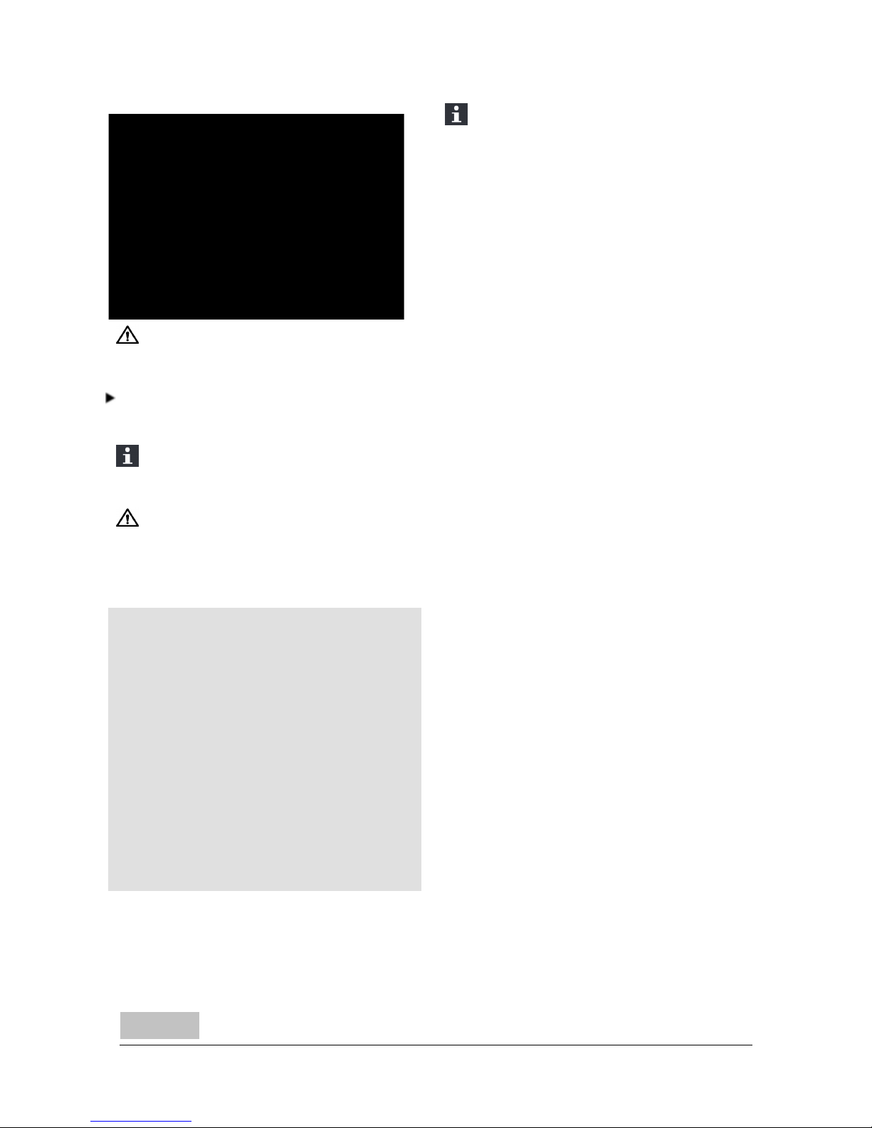
The airsupply tube is 100 mm in diameter. If the tube
is smooth, it may be no longer than 12 metres. If
accessories such as bends are used, the maximum
length (12 m) must be reduced by 1 m for each
accessory used.
1. Close the air inlet in the bottom plate with the
small cast-iron cover plates (1) and screws (2);
see following figure.
By closing the air inlet in the bottom plate you
prevent air being used for combustion from an
insufficiently ventilatedspace.
2. For connection to outside air via the floor:
a. Make an opening in the floor; see 'Appendix 2,
Measurements' for the correct position of the
opening.
b. Connect the foot hermetically to the floor using
a rubber seal.
c. Slide a straight air supply tube onto the
connection collar of the stove, so that it cannot
move; see following figure .
8
Subjectto change because of technicalimprovements
Page 10
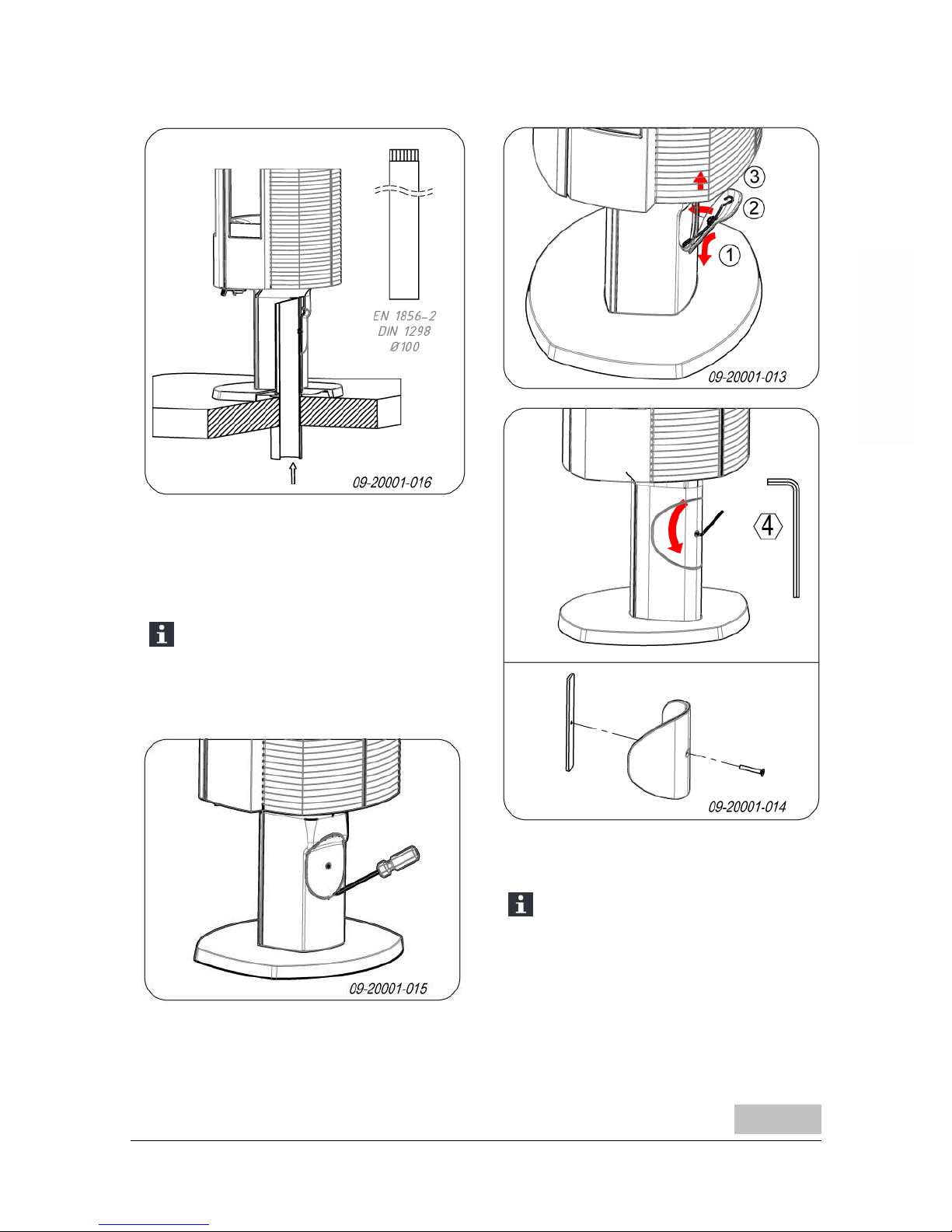
3. For connection to outside air via the rear of the
appliance:
a. Create an opening in the base or the log
compartment by removing the panel at the
back of the base or the logcompartment; see
following figures.
Depending on the version of the stove the
cover plate is affixed either with springy
clips or with a washer plate. In case of a
springfixing use a screwdriverto lift the
cover plate out of its groove.
b. Connect a so-called 'elbow' hermetically to the
opening in the base orthe logcompartment so
that it cannot move; see following figure.
The height for the connection through the
wall may vary dependingon the elbow
type.
Subjectto change because of technicalimprovements
9
Page 11

EN 1856-2
DIN 1298
Ø100 - 90°
09-20001-017
Installing and connecting
1. Position the stove in the correct place, and make
sure it is level.
2. Connect the appliance airtight to the flue
(chimney).
3. In the case of connection to outside air: connect
the outside air supply to the connection collar
within the base or log compartment of the stove or
to the fitted elbow.
4. Re-position all removed parts in the correct places
in the stove.
Never light a fire in the appliance without the
fireproof inner plates.
The appliance is now ready for use.
Use
First use
When you use the stove for the first time, make an
intense fire and keep it going for a good few hours.
This will cure the heat-resistant paint finish. This may
result in some smoke andodours. You could open
windows and doors for a while in the area in which the
stove is located.
Fuel
This stove is only suitable for burning natural wood;
sawn and chopped wood that is sufficiently dry.
Do not use other fuels, as they can cause serious
damage to the stove.
You are not allowedto use the following fuels, as they
pollute the environment and because they heavily soil
the appliance and flue, which may lead to a chimney
fire:
Treated wood, such as scrap wood, paintedwood,
impregnated wood, preserved wood, plywood and
chipboard.
Plastics, scrap paper anddomestic waste.
for example the drain connector orthe connections for
temperature sensors.
Wood
Hardwood, such as oak, beech, birch andfruit tree
wood is the ideal fuel for your stove. This type of
wood burns slowly with calm flames. Softwood
contains more resins, burns faster andsparks
more.
Use seasoned wood that contains no more than
20% moisture. The wood should have been
seasoned for at least 2 years.
Saw the wood to size andsplit it while it is still
fresh. Fresh woodis easierto split, and split wood
dries more easily. Store the woodunder a roof
wherethe wind has free access.
Do not use damp wood. Damp logs do not produce
heat as all the energy is usedin the evaporation of
moisture. This will result in a lot of smoke and soot
deposits on the stove door and in the chimney. The
water vapour will condense in the stove and can
leak away through chinks in the stove, causing
black stains on the floor. It may also condense in
the chimney and form creosote. Creosote is a
highly flammable compound and may cause a
chimney fire.
Lighting
You can check whether the flue has sufficient draught
by lighting a ball of paper above the baffle plate. A cold
flue often has insufficient draught and consequently,
some smoke may escape into the room insteadof up
the chimney. You can avoid this problem by lighting
the fire as described below.
10
Subjectto change because of technicalimprovements
Page 12

1. Stack two layers of medium sized logs crosswise.
2. Stack two layers of kindling crosswise on top of
the logs.
3. Place a firelighter cubein the lowerlayer of
kindlingand light the cube accordingto the
instructions on the packaging.
4. Close the door of the appliance and open the
primary air inlet and open the secondary air inlet of
the appliance; see 'Controlling air combustion'.
5. Allow the fire develop into a good blaze until there
is glowing bedof charcoal. You can then add fuel
andadjust the appliance, see the chapter"Stoking
with wood".
Burning wood
After you have followed the instructions for lighting :
1. Slowly openthe stove door.
2. Spreadthe charcoal evenly across the bottom of
the stove base.
3. Stack a few logs on the charcoal.
Open stacking
If the logs are stacked openly, the woodwill burn
quickly as the oxygen can reach each log easily. If
you want to use the stove for a short while, make an
open stack.
Compact stacking
If the logs are stacked tightly, the wood will burn more
slowly as the oxygen can only reach some logs
easily. If you want to burn wood for a longer period,
make a compact stack.
4. Close the door of the appliance.
5. Close the primary air inlet and leave the secondary
air inlet open.
Fill the appliance up to one third capacity.
Subjectto change because of technicalimprovements
11
Page 13

Controlling combustion air
The appliance has various features for aircontrol; see
following figure.
1.
The primary air slide is open in pulled out
position and closed in pushed back position.
2.
The secondary air slide is open in pulled out
position and closed in pushed back position.
The primary air slide controls the air flow under the
grille (1);see following figure.
The secondary air slide controls the air flow for the
glass and the vents in the back wall (2).
The baffle plate has permanent vents (3) that allow for
post-combustion.
Advice
Never burn woodwith an open door.
Regularly burn wood with intense roaring fires.
If you frequently have low intensity fires, tar
andcreosote may be deposited in the chimney
. Tar and creosote are highly combustible
substances. Thicker layers of these
substances may catch fire if the temperaturein
the chimney increases suddenly. By allowing
the fire to burn very intensely regularly, layers
of tar and creosote will disappear.
Low intensity fires also cause tar deposits on
the stove window and door.
When the outside temperature is not very low,
it is better to burn wood intensely for a few
hours instead of havinga low intensity fire for a
longperiodof time.
12
Subjectto change because of technicalimprovements
Page 14

Control the air supply with the secondary air inlet.
The secondary air inlet not only supplies air to
the fire but to the glass as well, so that it does
not quickly become dirty.
Open the primary air inlet for the time being if the air
supply by the secondary air inlet is inadequate or if
you want to fan the fire.
It is better to add a small amount of logs regularly
than to add many logs at the same time.
Extinguishing the fire
Do not add fuel and just let the fire goout. If a fire is
damped down by reducingthe air supply, harmful
substances will be released. For this reason, the fire
shouldbe allowed to go out naturally. Keepan eye on
the fire until it has gone out. All air inlets can be closed
once the fire has died completely.
Removing ashes
After the wood has been burnt, a relatively small
amount of ashes is left over. This bed of ashes is a
good insulating layer for the stove base plate and
improves combustion. It is goodto leave a thin layer
of ashes on the stove base plate.
The flow of air through the fire plate must not be
obstructed, however, andno ash may be allowed to
accumulate behind a cast-ironinner plate. Remove
the excess ash regularly.
1. Open the appliance door and use the scraper to
open the ash removal port in the bottom of the fire
compartment.
2. Using the scraper, sweepthe excess ashes
throughthe ash removal port into the ash pan
underneath.
3. Close the ash removal port.
4. Remove the ashtray (see next figure)using the
glove provided andempty the ashtray.
5. Replace the ash pan and close the stove door.
Fog and mist
Fog and mist hinderthe flow of flue gases through the
flue. Smoke can blow back and cause a stench. If it is
not strictly necessary, it is better not to use the stove
in foggy andmisty weather.
Subjectto change because of technicalimprovements
13
Page 15

Solving problems
Refer to the appendix "Diagnostic diagram" to resolve
any problems in using the stove.
To reach the nominal output, approximately 2
kg of fuel needs to be burnt every 45 minutes.
Maintenance
Follow the maintenance instructions in this chapter to
keep the stove in good condition.
Chimney
In many countries, you are required by law to have
your chimney checked and maintained.
At the beginning of the heating season: have the
chimney swept by an expert.
Duringthe heating season and after the chimney
has not been usedfor a long time: have the
chimney checked for soot deposits.
After the heating season: seal off the chimney with
a ball of paper.
Cleaning and other regular
maintenance activities
Do not clean the stove when it is still warm.
Clean the exterior of the stove with a dry lint-free
cloth.
You can cleanthe stove interior thoroughly at the end
of the heating season:
If necessary, first remove the fire-resistant inner
plates. See the chapter "Installation" for
instructions on removing and installing the inner
plates.
If necessary, cleanthe airsupply ducts. Remove
the top plate to this end. The top plate lies loosely
on the appliance.
If required, remove the baffle plate at the top of the
appliance and clean it.
Remove and install baffle plate
Unscrew the clamping plate on the front of the baffle
plate. Lift the baffle plate from the support and tilt the
baffle plate out of the appliance. Please ensure that
the rear of the baffle plate properly connects to the air
tunnel at the back of the appliance when reinstalling.
Checking fire-resistant inner plates
The fire-resistant inner plates are consumables and
subject to wear . Check the fire-resistant inner plates
frequently and replace them when necessary.
See the chapter "Installation" for instructions on
removing and installing the inner plates.
The insulating vermiculite or chamotte inner
plates may develop hairline cracks, but this
does not affect their performance adversely.
Cast-iron inner plates last a longtime if you
remove frequently the ash that can accumulate
behind them. If accumulatedash behind the
cast-iron plate is not removed, the plate will no
longer be able to dissipate the heat to the
surroundings and this may cause the plate to
warp orcrack.
Never use the stove without the fire-resistant
inner plates.
Cleaning glass
Dirt clings less easily to well-cleaned glass. Proceed
as follows:
14
Subjectto change because of technicalimprovements
Page 16

1. Remove dust and loose soot with a dry cloth.
2. Clean the glass with stove glass cleaner:
a. Apply stove glass cleaner to a kitchen sponge,
rubdown the entire glass surface and give the
cleaning agent time to react.
b. Remove the dirt with a moist cloth or kitchen
tissue.
3. Clean the glass again with a normal glass cleaning
product.
4. Rub the glass cleanwith a dry cloth or kitchen
tissue.
Do not use abrasive or aggressive products to
clean the glass.
Wear household gloves to protect your hands.
If the glass in the appliance is broken or
cracked, it must be replaced before you can
use the appliance again.
Make sure that no stove window cleaner runs
between the glass and the cast-iron door.
Lubrication
Although cast-ironis slightly self-lubricating, you will
still need to lubricate moving parts frequently.
Lubricate the moving parts (such as guide
systems,hingepins, latches andair slides) with
heat resistant grease that is available in the
specialist trade.
Touching-up the paint finish
Small areas of damaged paint finish can be touchedup with a spray can of special heat-resistant paint,
available from yoursupplier.
Areas of damaged enamel can be touched up with a
special heat-resistant paint finish that is available
from your supplier.
Checking the seal
Check whether the door sealingrope is still in good
conditionand works well. The sealing rope is
subject to wear and will need to be replaced over
time.
Check the appliance for air leaks. Close any
chinks with stove sealant.
Allow the sealant to harden fully beforelighting
the stove, as any moisture in the sealant will
form bubbles, resulting in a new air leak.
Subjectto change because of technicalimprovements
15
Page 17

Appendix 1: Technical Data
Model / Modèle / Modell Astro 3 / Astro 4
Nominaal vermogen / Puissance nominale /
Nominal heat output / Nominalleistung
8 kW
Schoorsteenaansluiting (diameter) /
Raccordement cheminée (diamètre)/ Connection
to chimney (diameter) / Schornsteinanschluss
(Diameter)
150mm
Gewicht / Poids / Weight +/- 140 kg
Aanbevolenbrandstof / Combustible conseillés /
Recommendedfuel / EmpfohleneBrennstoffe
Hout / Bois / Wood / Holz
Kenmerk brandstof / caractéristique combustible /
Fuel property / KennzeichenBrennstoffe
maximum length 25 cm
Massadebiet van rookgassen / Débit des fumées
/ Flue gas mass flow / Abgasstutzentemperatuur
7.5 g/s
Rookgastemperatuur gemeten in de meetsectie /
Températuredes fumées au niveaudu tronçon de
mesure / Flue gas temperature measuredin the
test measurement section / Abgas-temperatur
gemessen in derMessstrecke
299°C
Temperatuurgemeten aan de uitgang van het
toestel / température enaval de la buse /
Temperaturedirectly downstream flue spigot /
Abgastemperatur gemessen im Abgasstutzen
367°C
Minimum trek / Dépression minimal / Minimum
draught / Mindesförderdruck
12 Pa
% CO (13% O2) 0.09 %
% NOx (13% O2) 160 mg/Nm³
CnHm (13% O2) 70 mg/Nm³
Stof-emissie/ articulate-emission / Particulate
emission / StaubEmission
23 mg/Nm³
Stof-emissie volgens NS3058-NS3059 /
émissions selon la norme NS3058-NS3059/
Particulate emission according to NS3058NS3059 / Staub Emission gemessen nach
NS3058-NS3059
2.7 g/kg
Rendement / Rendement / Efficiency /
Wirkungsgrad
76.4 %
16
Subjectto change because of technicalimprovements
Page 18

Appendix 2: Measurements
ASTRO 3CBP
Subjectto change because of technicalimprovements
17
Page 19

ASTRO 3CBWB
18
Subjectto change because of technicalimprovements
Page 20

ASTRO 4CBP
Subjectto change because of technicalimprovements
19
Page 21

ASTRO 4CBWB
20
Subjectto change because of technicalimprovements
Page 22

Appendix 3: Distance from combustible material
ASTRO 3 PEGASUS
Minimum distances for versions without heat shield:
If the distance between the connecting tube and combustible materials is less than 300 mm the
connecting tube should be protected.
1. Combustible material
2. Incombustible material, thickness 100mm
Subjectto change because of technicalimprovements
21
Page 23

Minimum distances for versions with heat shield:
1. Combustible material
2. Incombustible material, thickness 100mm
ASTRO 4 LEON
Minimum distances for versions without heat shield:
If the distance between the connecting tube and combustible materials is less than 300 mm the
connecting tube should be protected.
1. Combustible material
2. Incombustible material, thickness 100mm
22
Subjectto change because of technicalimprovements
Page 24

Minimum distances for versions with heat shield:
1. Combustible material
2. Incombustible material, thickness 100mm
ASTRO 3 PEGASUS and ASTRO 4 LEON - Dimensions fireproof floor plate
A
B B
09-20002-004
Minimal dimensions of fireproof protective plate
A (mm) B (mm)
Din 18891 500 300
Germany 500 300
Finland 400 100
Norway 300 100
Subjectto change because of technicalimprovements
23
Page 25

Appendix 4: Diagnostic diagram
Problem
Wood will not stay lit
Gives off insufficient heat
Smoke emissions into the room when adding wood
Fire in stove is too intense, is hard to adjust
Deposit on the glass
Possible cause Possible solution
Insufficient draught
A cold flue usuallyfailsto create sufficient draught. Follow the
instructionsfor lightingin the "Use" chapter; open a window.
Wood too damp Use wood with no more than 20%moisture.
Logs too large
Use small pieces of kindling. Use split logs no larger than 30 cm in
circumference.
Wood stacked incorrectly
Stackthe logsin a way that allows adequate air flow between the
logs(open stacking,see "Burning wood")
Chimney does not work properly
Check whether the chimneymeets the requirements: at least 4
metres high, right diameter, wellinsulated, smooth inside,not too
many bends, no obstructions in chimney(bird's nest, too much soot
deposit), hermetically tight (no chinks).
Chimney stack incorrect Sufficiently high above the roof, no obstaclesin the vicinity
Air inlets setincorrectly Open the air inlets completely.
Stove connected to the chimney
incorrectly
Connection should be hermeticallytight.
Vacuum in area in whichthe stove is
installed
Switch off extraction systems.
Insufficient supply of fresh air
Provide an adequate air supply;if necessary useoutside air
connection.
Adverse weather conditions?
Inversion (reversed air flow in chimney
because of a high outside temperature),
extreme wind speeds
We recommend you don't use the appliance in the case of inversion.
If required, install an extra hood on the flue to increase the draught.
Draught inthe living room
Avoiddraught inthe living room, do not place the appliance near a
door or heating air ducts.
Flames touchthe glass
Make sure the wood isnot positioned too close to the glass. Slide the
primary air inlet cover closer to the "Closed" position.
Stove is leaking air Check the door seals and stove joints.
24
Subjectto change because of technicalimprovements
Page 26

Subjectto change because of technicalimprovements
25
Index
A
Adding fuel 13
Adding wood
smoke emissions into the room 24
Air control 12
Air inlets 11
Air leak 15
Air supply for fire 13
Ash pan
remove 6
Ash removal port 13
Ashes
remove 13
Ashtray
open 13
B
Bearing capacity of floor
Floors
bearing capacity 5
Burning wood 11
addfuel 13
adding logs 11
appliance is hard to adjust 24
fire is too intense 24
insufficient heat 14, 24
C
Carpet 5
Cast iron
fire resistant 6
inner plates 6
Cast iron inner plates 6
Chimney
connection to 10
height 4
sweep 14
Chinks in appliance 15
Clean
glass 14
Cleaning
appliance 14
Combustible material
distance from 21
Connection
measurements 17
Connection collar for connection to chimney 7
Connection set for outside air supply 8
Connection to chimney
at top 7
top 7
Connection to outside air supply 8
Control air supply 13
Control of air 12
Cover on flue 4
Creosote 12
D
Damage 6
Damp wood 10
Door
open 6
sealingrope 15
Draught 16
Drying wood 10
E
Efficiency 16
F
Filling height 11
Fire
extinguishing 13
lighting 10
Fire-resistant inner plates
maintenance 14
remove 6
Fire going out 13
Fire safety
distance from combustible material 21
floor 5
furniture 5
walls 5
Fireproof inner plates
warning 10
Floors
fire safety 5
Page 27

Flue
connection diameter 16
maintenance 14
requirements 3
Flue gas
mass flow 16
temperature 16
Fog, do not burn wood 13
Foot
cover plate 9
Fuel
adding 13
adding wood 11
necessary amount 14
required amount 14
suitable 10
unsuitable 10
wood 10
G
Glass
clean 14
deposit 24
H
Heat, insufficient 14
Heat,insufficient 24
Hood onthe flue 4
I
Innerplates
cast iron 6
vermiculite 6
Innerplates, fire-resistant
remove 6
Install
connection set for outside air supply 8
Installation
measurements 17
K
Kindled fire 10
Kindling 24
L
Lighting 10
Lubricant 15
Lubricate 15
M
Maintenance
chimney 14
clean glass 14
cleaning the appliance 14
fire-resistant inner plates 14
lubrication 15
sealing 15
Measurements 17
Mist, do not burnwood 13
N
Nominal heat output 16
Nominal output 14
O
Open
ash removal port 13
ashtray 13
door 6
Outside air
install connection set 8
Outside airintake
connection to 10
Outside airsupply connection 8
P
Paint finish 10
Particulates
emission 16
Parts, removable 6
Prevent a chimney fire 12
Primary air inlet 11
R
Removable parts 6
Removal of ashes 13
Remove
ash pan 6
fire-resistant inner plates 6
Remove ashes 13
S
Scraper for ash removal 13
Screens
clean 14
26
Subjectto change because of technicalimprovements
Page 28

Subjectto change because of technicalimprovements
27
deposit 24
Sealing rope for door 15
Secondary air inlet 11
Smoke
on first use 10
Smoke emissions into the room 3, 24
Softwood 10
Solving problems 14, 24
Stacking logs 11
Storingwood 10
Stove window cleaner 14
Suitable fuel 10
Supply of outside air 4
Sweep chimney 14
T
Tar 12
Temperature 16
U
Unsuitable fuel 10
V
Ventilation 4
connect outside air supply 8
ruleof thumb 4
Ventilationlouvre 4
Vermiculite
fire-resistant 6
Vermiculite inner plates 6
W
Walls
fire safety 5
Warning
chimney fire 3, 10, 12
combustible materials 3
fireproof inner plates 10
glass broken or cracked 3, 15
hot surface 3
regulations 3
stove window cleaner 15
terms and conditions for insurance 3
ventilation 3-4
Weatherconditions, do not burn wood 13
Weight 16
Wood 10
damp 10
does not keep burning 24
drying 10
right sort 10
storing 10
Page 29

Page 30

Page 31

Page 32

E & O E
 Loading...